EP3840557A1 - Elektrisches gerät mit einer elektrischen anschlussleiste, die von zwei seiten eines kühlkörpers gekühlt wird - Google Patents
Elektrisches gerät mit einer elektrischen anschlussleiste, die von zwei seiten eines kühlkörpers gekühlt wird Download PDFInfo
- Publication number
- EP3840557A1 EP3840557A1 EP20211828.7A EP20211828A EP3840557A1 EP 3840557 A1 EP3840557 A1 EP 3840557A1 EP 20211828 A EP20211828 A EP 20211828A EP 3840557 A1 EP3840557 A1 EP 3840557A1
- Authority
- EP
- European Patent Office
- Prior art keywords
- heat sink
- electrical connection
- connection bar
- electrical
- electrical equipment
- Prior art date
- Legal status (The legal status is an assumption and is not a legal conclusion. Google has not performed a legal analysis and makes no representation as to the accuracy of the status listed.)
- Granted
Links
Images

Classifications
-
- H—ELECTRICITY
- H05—ELECTRIC TECHNIQUES NOT OTHERWISE PROVIDED FOR
- H05K—PRINTED CIRCUITS; CASINGS OR CONSTRUCTIONAL DETAILS OF ELECTRIC APPARATUS; MANUFACTURE OF ASSEMBLAGES OF ELECTRICAL COMPONENTS
- H05K7/00—Constructional details common to different types of electric apparatus
- H05K7/20—Modifications to facilitate cooling, ventilating, or heating
- H05K7/2089—Modifications to facilitate cooling, ventilating, or heating for power electronics, e.g. for inverters for controlling motor
- H05K7/209—Heat transfer by conduction from internal heat source to heat radiating structure
-
- H—ELECTRICITY
- H05—ELECTRIC TECHNIQUES NOT OTHERWISE PROVIDED FOR
- H05K—PRINTED CIRCUITS; CASINGS OR CONSTRUCTIONAL DETAILS OF ELECTRIC APPARATUS; MANUFACTURE OF ASSEMBLAGES OF ELECTRICAL COMPONENTS
- H05K7/00—Constructional details common to different types of electric apparatus
- H05K7/20—Modifications to facilitate cooling, ventilating, or heating
- H05K7/2039—Modifications to facilitate cooling, ventilating, or heating characterised by the heat transfer by conduction from the heat generating element to a dissipating body
-
- H—ELECTRICITY
- H02—GENERATION; CONVERSION OR DISTRIBUTION OF ELECTRIC POWER
- H02G—INSTALLATION OF ELECTRIC CABLES OR LINES, OR OF COMBINED OPTICAL AND ELECTRIC CABLES OR LINES
- H02G5/00—Installations of bus-bars
- H02G5/10—Cooling
-
- H—ELECTRICITY
- H02—GENERATION; CONVERSION OR DISTRIBUTION OF ELECTRIC POWER
- H02M—APPARATUS FOR CONVERSION BETWEEN AC AND AC, BETWEEN AC AND DC, OR BETWEEN DC AND DC, AND FOR USE WITH MAINS OR SIMILAR POWER SUPPLY SYSTEMS; CONVERSION OF DC OR AC INPUT POWER INTO SURGE OUTPUT POWER; CONTROL OR REGULATION THEREOF
- H02M7/00—Conversion of AC power input into DC power output; Conversion of DC power input into AC power output
- H02M7/003—Constructional details, e.g. physical layout, assembly, wiring or busbar connections
-
- H—ELECTRICITY
- H05—ELECTRIC TECHNIQUES NOT OTHERWISE PROVIDED FOR
- H05K—PRINTED CIRCUITS; CASINGS OR CONSTRUCTIONAL DETAILS OF ELECTRIC APPARATUS; MANUFACTURE OF ASSEMBLAGES OF ELECTRICAL COMPONENTS
- H05K7/00—Constructional details common to different types of electric apparatus
- H05K7/14—Mounting supporting structure in casing or on frame or rack
- H05K7/1422—Printed circuit boards receptacles, e.g. stacked structures, electronic circuit modules or box like frames
- H05K7/1427—Housings
- H05K7/1432—Housings specially adapted for power drive units or power converters
- H05K7/14329—Housings specially adapted for power drive units or power converters specially adapted for the configuration of power bus bars
-
- H—ELECTRICITY
- H05—ELECTRIC TECHNIQUES NOT OTHERWISE PROVIDED FOR
- H05K—PRINTED CIRCUITS; CASINGS OR CONSTRUCTIONAL DETAILS OF ELECTRIC APPARATUS; MANUFACTURE OF ASSEMBLAGES OF ELECTRICAL COMPONENTS
- H05K7/00—Constructional details common to different types of electric apparatus
- H05K7/20—Modifications to facilitate cooling, ventilating, or heating
- H05K7/2089—Modifications to facilitate cooling, ventilating, or heating for power electronics, e.g. for inverters for controlling motor
- H05K7/20927—Liquid coolant without phase change
-
- H—ELECTRICITY
- H05—ELECTRIC TECHNIQUES NOT OTHERWISE PROVIDED FOR
- H05K—PRINTED CIRCUITS; CASINGS OR CONSTRUCTIONAL DETAILS OF ELECTRIC APPARATUS; MANUFACTURE OF ASSEMBLAGES OF ELECTRICAL COMPONENTS
- H05K7/00—Constructional details common to different types of electric apparatus
- H05K7/20—Modifications to facilitate cooling, ventilating, or heating
- H05K7/2089—Modifications to facilitate cooling, ventilating, or heating for power electronics, e.g. for inverters for controlling motor
- H05K7/20936—Liquid coolant with phase change
Definitions
- the present invention relates to the field of electrical equipment, in particular for electric or hybrid vehicles, and more specifically relates to the cooling of electrical systems such as inverters connected to the motor in electric motorization systems.
- electrical connection bars are intended to route electrical energy from an interface, in particular an external interface, from the electrical equipment to an internal component of the electrical equipment.
- the electrical connection bar connects a terminal of the electrical equipment with a capacitor of the electrical equipment.
- the electrical connection bar generally comprises an electrically conductive bar, in particular metallic, held by a body of electrically insulating material, in particular plastic. Electrical components can be received on the electrical connection bar to allow filtering of the signal flowing through the electrical conductor bar. When the current passes through the electrical connection bar, the heat given off by the electrical conductor and / or the filtering components can damage the other components of the electrical equipment, in particular the capacitor, which already generates heat by the Joule effect. due to its own functioning.
- a cooling solution is therefore sought which allows improved heat dissipation of the electrical conduction bars.
- the electrical connection bar is therefore cooled by the two opposite faces of the heat sink.
- only one face of the heat sink is used to cool the electrical connection bar.
- said electrical connection bar comes into direct contact with said two opposite faces of the heat sink, or comes against the opposite faces of the heat sink via one or more intermediate layers.
- the electrical connection bar extends along the two opposite faces so as to surround the heat sink.
- the heat sink comprises a first side at the level of which said two opposite faces are connected, said electrical connection bar extending along said heat sink from the first side returning to said first side.
- an input terminal and an output terminal of the electrical connection bar are at said first side of the heat sink.
- the heat sink comprises a second side at the level of which said two opposite faces are connected, said second side being opposite to the first side.
- Said electrical connection bar extends along said heat sink from the first side to the second side, then from the second side to the first side.
- the electrical connection bar comprises two parts assembled together, the first part coming against a first of said faces of the heat sink and the second part coming against the second of said faces of the heat sink, so as to surround the heat sink.
- the first part and the second part of the electrical connection bar are assembled together at the level of the second edge of the heat sink.
- the electrical connection bar is made in one piece, surrounding the heat sink.
- the electrical connection bar comprises a coating surrounding an electrical conduction bar, the coating comprising an opening coming in front of a portion of the heat sink, the opening comprising an electrically insulating heat dissipating material so as to improve the cooling of said electric conduction bar.
- the electrical connection bar supports at least one electrical component.
- the electrical component is an EMC filtering component.
- the electrical component is sandwiched between the electrical connection bar and the heat sink.
- At least one of said faces of the heat sink is configured to cool other components on at least one surface not covered by the electrical connection bar.
- the first face of the heat sink receives a power electronic module and the second face of the heat sink receives a capacitive module at surfaces not covered by the electrical connection bar.
- the heat sink comprises at least one cooling channel configured to receive a cooling fluid, the cooling channel being at least partly in the area not covered by the electrical connection bar, and the part of the heat sink surrounded by the electrical connection bar being devoid of cooling channel.
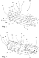
- Electrical equipment 100 as illustrated by figure 1 comprises a heat sink 2, which comprises an internal volume delimited by at least two opposite faces 20a, 20b.
- a part of the heat sink 2 called the main part 2a, may include a cooling channel 21 configured to receive a cooling fluid.
- Another part of the heat sink, called auxiliary part 2b is then devoid of a cooling channel.
- the auxiliary part 2b is in particular cooled by thermal conduction from the auxiliary part 2b to the main part 2a where the heat is drained by the cooling fluid circulating in the cooling channel 21.
- the auxiliary part 2b forms a protuberance. of material from the main part 2a.
- the heat sink 2 can have a substantially rectangular shape.
- the auxiliary part 2b could receive a cooling channel, which would increase its size but would improve the heat dissipation at the level of the auxiliary part 2b.
- an auxiliary part 2b devoid of a cooling channel is sufficient for cooling an electrical connection bar, in particular as described below.
- the auxiliary part 2b could be made of a material different from that of the main part 2a.
- the auxiliary part 2b could be made of a material with a higher thermal conductivity than that of the main part 2a.
- the main part 2a is made of aluminum and the auxiliary part 2b is made of copper.
- the cost could be significantly higher.
- the two opposite faces 20a, 20b can have a substantially identical contour. They can be superimposed in a substantially parallel fashion.
- the contours of the two opposite faces 20a, 20b are in particular connected by a wall 3 all along the contours. Alternatively, the contours of the two opposite faces can be connected directly to each other, in particular without a wall 3.
- the opposite faces 20a, 20b can include notches, openings or other differences with respect to the other opposite face 20a, 20b.
- the electrical equipment comprises an electrical connection bar 4.
- the electrical connection bar 4 may comprise two electrical conduction bars 41 a, 41 b (or "leadframe" in English), in particular a negative conduction bar 41a and a bar of positive conduction 41b.
- the electrical conduction bars 41a, 41b are in particular made of metal, for example copper. They form rigid parts which are held together by a coating 42 of electrically insulating material, deposited for example by overmolding. In figure 1 , part of the coating 42 is not shown in order to make the electrical conduction bars 41a, 41b visible.
- the electrical conduction bars 41a, 41b connect in particular terminals of the electrical equipment 100 with a capacity of the electrical equipment 100.
- the electrical connection bar 4 comes into contact against the two opposite faces 20a, 20b of the heat sink 2 so as to be cooled by the heat sink 2.
- the electrical connection bar 4 takes advantage of two faces of the heat sink 2 to be cooled.
- the integration of the electrical connection bar 4 in the electrical equipment 100 is improved compared to the prior art.
- the cooling of the electrical connection bar 4 is improved while controlling the bulk of the electrical equipment 100.
- the electrical connection bar 4 extends in particular along the two opposite faces 20a, 20b of the heat sink 2 in such a manner. to surround the heat sink 2.
- the electrical connection bar 4 can therefore be cooled over its entire length.
- the surfaces of the electrical connection bar 4 which are cooled are therefore increased compared to the prior art.
- the cooling of the electrical connection bar 4 is then higher, the risk of damage by heat therefore greatly reduced. Further by surrounding the heat sink 2, the electrical connection bar 4 is integrated with the heat sink 2.
- the electrical connection bar 4 starts from a first side 3a of the heat sink 2; extends along the auxiliary part 2b, in particular along the portion of the first face 20a included in the auxiliary part 2b.
- the connection bar 4 then joins the second face 20b via a second side 3b of the heat sink 2, and again runs along the auxiliary part 2b, in particular along the portion of the second face 20b included in the auxiliary part 2b, to return on the first side 3a.
- the electrical connection bar 4 forms a loop around the heat sink 2, in particular around the auxiliary part 2b.
- the electrical connections to the electrical connection bar 4 can be provided in a similar fashion.
- this arrangement makes it possible to connect the electrical connection bar 4 more easily.
- the two connections can therefore be made from the same side of the heat sink 2, without turning over the electrical equipment 100; which saves a manufacturing step and also time. Unnecessary handling of the electrical equipment 100 during assembly is therefore avoided and / or quality control is therefore facilitated.
- the second side 3b is opposite the first side 3a.
- this second side 3b could be a side of the heat sink 2 which is adjacent to the first side 3a.
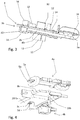
- the connection bar 4 comprises in particular two parts 4a, 4b assembled together so as to surround the heat sink 2.
- the first part 4a comes against the first face 20a of the heat sink 2; and the second part 4b comes against the second face 20b of the heat sink 2.
- the assembly of the electrical connection bar 4 around the heat sink 2 can be done in several steps.
- the first part 4a and the second part 4b of the electrical connection bar 4 are assembled together at the second side 3b of the heat sink 2.
- the electrical conduction bars 41 a, 41 b each have a first part coming against the first face 20a and a second part coming against the second face 20b.
- ends 5a, 5b of the first parts of the electrical conduction bars 41a, 41b come against respective ends 5c, 5d of the second parts of the electrical conduction bars 41a, 41b.
- These ends 5a, 5b, 5c, 5d are connected by welding, brazing, screwing or any other fixing means.
- the arrangement described above allows assembly of the electrical connection bar 4 with the heat sink 2 along a single axis.
- connection bar 4 could be in one piece, surrounding the heat sink 2.
- the electrical conduction bars 41a, 41b are then each in one piece, and in particular extend continuously from the first face 20a to the second face 20b.
- this variant makes it possible to save parts, for example parts connecting the first 4a and second 4b parts of the electrical connection bar 4, and / or pre-assembly steps. In addition, possible assembly in the wrong direction is avoided.
- the coating 42 of the connection bar 4 may include one or more openings 40 facing the heat sink 2.
- the opening 40 in particular reveals a surface of the electrical conduction bar 41a, 41b.
- This opening 40 is then filled with an electrically insulating material, but thermally conductive which acts so as to improve the cooling of the electric conduction bar 41a, 41b.
- the material may be a thermal grease or a flexible material, such as for example a “gap pad” ® or any other material with dual characteristics of electrical insulation and thermal conduction.
- the electrical connection bar 4 can support components 12, 16.
- These components 12, 16 can be assembled on an electronic card 14, (in English "electronic board") which is itself mounted on the electrical connection bar 4, in particular on the coating 42 of the electrical connection bar 4.
- the electronic card 14 receives in particular small electrical elements size, of which a direct assembly on the electrical connection bar 4 would be difficult.
- the filtering makes it possible to reduce the electromagnetic field CEM linked to the current flowing in the electrical connection bar 4 in order to protect the components of the electrical equipment 100.
- Other components can be placed on another electronic card and connected to the control bar. electrical connection 4 by cables, layers or a rigid connector.
- the components 12, 16 can be mounted directly on the electrical connection bar 4, without the intermediary of the electronic card 14.
- the components 12, 16 can be welded, soldered or fixed by any other method of fixing on the electrical connection bar 4.
- the electrical connection bar 4 comes against the heat sink 2 at the level of the auxiliary part 2b of the heat sink 2.
- the electrical connection bar 4 covers only one area on the heat sink 2.
- the heat sink bar. electrical connection 4 covers only one area of the auxiliary part 2b of the heat sink 2.
- the rest of the heat sink 2, in particular the portions of the first 20a and second 20b faces located in the main part 2a, can receive other components for cool them.
- an opening 22 in the first face 20a of the heat sink 2 is closed by a plate carrying an electronic power module. The plate, by closing the opening 22 of the first face 20a contributes in particular to forming the cooling channel located in the main part 2a of the heat sink 2.
- a portion 201b of the second face 20b located in the main part 2b can receive a capacity which will be cooled by the main part 2a.
- the power module and the capacitor generally emit a lot of heat by the Joule effect, it is advantageous to arrange them on the main part 2a of the heat sink.
- the components 12, 16 may be sandwiched between the electrical connection bar 4 and the heat sink 2, which improves the cooling of the components 12, 16.
- the structure of the faces 20a , 20b of the heat sink 2 can be adapted to the size of the components 12, 16.
- the surface of the heat sink 2 against which the components 12, 16 come against can take into account the different heights and shapes of the components 12, 16 in order to ensure their cooling. For example, starting from the heat sink 2, there is first a layer of a flexible material 42, electrically insulating but thermally conductive, then the component 12, 16, followed by the electronic card 14 and the connection bar electrical 4. Such a sandwich arrangement also allows a firm hold of the components 12, 16. The degradation by vibration is then attenuated. The longevity of the electrical equipment 100 is increased.
Landscapes
- Engineering & Computer Science (AREA)
- Microelectronics & Electronic Packaging (AREA)
- Physics & Mathematics (AREA)
- Thermal Sciences (AREA)
- Power Engineering (AREA)
- Cooling Or The Like Of Electrical Apparatus (AREA)
- Inverter Devices (AREA)
Applications Claiming Priority (1)
| Application Number | Priority Date | Filing Date | Title |
|---|---|---|---|
| FR1914810A FR3105716B1 (fr) | 2019-12-18 | 2019-12-18 | Équipement électrique comprenant une barre de connexion électrique refroidie par deux faces d’un dissipateur thermique |
Publications (2)
| Publication Number | Publication Date |
|---|---|
| EP3840557A1 true EP3840557A1 (de) | 2021-06-23 |
| EP3840557B1 EP3840557B1 (de) | 2023-11-08 |
Family
ID=70228166
Family Applications (1)
| Application Number | Title | Priority Date | Filing Date |
|---|---|---|---|
| EP20211828.7A Active EP3840557B1 (de) | 2019-12-18 | 2020-12-04 | Elektrisches gerät mit einer elektrischen anschlussleiste, die von zwei seiten eines kühlkörpers gekühlt wird |
Country Status (5)
| Country | Link |
|---|---|
| US (1) | US11770915B2 (de) |
| EP (1) | EP3840557B1 (de) |
| JP (1) | JP2021097594A (de) |
| CN (1) | CN113015398A (de) |
| FR (1) | FR3105716B1 (de) |
Families Citing this family (5)
| Publication number | Priority date | Publication date | Assignee | Title |
|---|---|---|---|---|
| US20250089225A1 (en) * | 2021-09-15 | 2025-03-13 | Marel Power Solutions, Inc. | Air cooled compact power systems |
| US12193202B2 (en) * | 2021-09-15 | 2025-01-07 | Marel Power Solutions, Inc. | Air cooled compact power systems |
| DE102021130733A1 (de) | 2021-11-24 | 2023-05-25 | Audi Aktiengesellschaft | Elektrische Schaltungseinrichtung und Kraftfahrzeug |
| FR3142646A1 (fr) | 2022-11-29 | 2024-05-31 | Nidec Psa Emotors | Filtre de compatibilité électromagnétique et onduleur équipé d’un tel filtre |
| CA3222477A1 (en) * | 2022-12-29 | 2024-06-29 | Enedym Inc. | Switched reluctance motor drive system for controlling pitch angle of wind turbine blades |
Citations (5)
| Publication number | Priority date | Publication date | Assignee | Title |
|---|---|---|---|---|
| US5574312A (en) * | 1994-06-17 | 1996-11-12 | Abb Management Ag | Low-inductance power semiconductor module |
| US20040256710A1 (en) * | 2001-09-28 | 2004-12-23 | Herbert Schwarzbauer | Device with power semiconductor components for controlling the power of high currents and use of said device |
| US20060207780A1 (en) * | 2005-03-17 | 2006-09-21 | Toyota Jidosha Kabushiki Kaisha | Electronic component housing structural body |
| WO2013136877A1 (ja) * | 2012-03-14 | 2013-09-19 | 日立オートモティブシステムズ株式会社 | 電力変換装置 |
| US20140062210A1 (en) * | 2012-09-04 | 2014-03-06 | General Electric Company | Mechanical layout for half-bridge power module that is optimized for low inductance |
Family Cites Families (5)
| Publication number | Priority date | Publication date | Assignee | Title |
|---|---|---|---|---|
| US20040060689A1 (en) * | 2002-09-27 | 2004-04-01 | Pfeifer David W. | Compact liquid cooled heat sink |
| JP5217884B2 (ja) * | 2008-10-14 | 2013-06-19 | 株式会社デンソー | 半導体装置 |
| JP6344215B2 (ja) * | 2014-11-21 | 2018-06-20 | 株式会社デンソー | 半導体装置及びパワーモジュール |
| US10057974B2 (en) * | 2016-11-04 | 2018-08-21 | Hamilton Sundstrand Corporation | Integrated panel level liquid cooling for bus bars |
| DE102019206872A1 (de) * | 2019-05-13 | 2020-11-19 | Rolls-Royce Deutschland Ltd & Co Kg | Minimalistischer Stromrichter und Fahrzeug mit einem Stromrichter |
-
2019
- 2019-12-18 FR FR1914810A patent/FR3105716B1/fr active Active
-
2020
- 2020-12-04 EP EP20211828.7A patent/EP3840557B1/de active Active
- 2020-12-15 JP JP2020207204A patent/JP2021097594A/ja active Pending
- 2020-12-15 CN CN202011473556.4A patent/CN113015398A/zh active Pending
- 2020-12-16 US US17/123,675 patent/US11770915B2/en active Active
Patent Citations (5)
| Publication number | Priority date | Publication date | Assignee | Title |
|---|---|---|---|---|
| US5574312A (en) * | 1994-06-17 | 1996-11-12 | Abb Management Ag | Low-inductance power semiconductor module |
| US20040256710A1 (en) * | 2001-09-28 | 2004-12-23 | Herbert Schwarzbauer | Device with power semiconductor components for controlling the power of high currents and use of said device |
| US20060207780A1 (en) * | 2005-03-17 | 2006-09-21 | Toyota Jidosha Kabushiki Kaisha | Electronic component housing structural body |
| WO2013136877A1 (ja) * | 2012-03-14 | 2013-09-19 | 日立オートモティブシステムズ株式会社 | 電力変換装置 |
| US20140062210A1 (en) * | 2012-09-04 | 2014-03-06 | General Electric Company | Mechanical layout for half-bridge power module that is optimized for low inductance |
Also Published As
| Publication number | Publication date |
|---|---|
| US11770915B2 (en) | 2023-09-26 |
| CN113015398A (zh) | 2021-06-22 |
| EP3840557B1 (de) | 2023-11-08 |
| FR3105716A1 (fr) | 2021-06-25 |
| KR20210078404A (ko) | 2021-06-28 |
| FR3105716B1 (fr) | 2022-07-01 |
| US20210195787A1 (en) | 2021-06-24 |
| JP2021097594A (ja) | 2021-06-24 |
Similar Documents
| Publication | Publication Date | Title |
|---|---|---|
| EP3840557B1 (de) | Elektrisches gerät mit einer elektrischen anschlussleiste, die von zwei seiten eines kühlkörpers gekühlt wird | |
| FR2791517A1 (fr) | Unite electronique de puissance pour commander un groupe electrique | |
| EP3672384A1 (de) | Elektrische anordnung von einer elektrischen stromschiene und eines kühlmoduls | |
| FR3098078A1 (fr) | Circuit imprimé et procédé pour la mesure de la température dans un connecteur électrique de puissance | |
| EP2692199B1 (de) | Wärmetauscher mit elektrischen heizelementen | |
| EP2979521A1 (de) | Steuermodul für eine elektrische anwendung | |
| EP3056070B1 (de) | Elektrisches modul, elektrischen system mit derartigem elektrischen modul und zugehörige herstellungsverfahren | |
| EP2536261A1 (de) | Elektronisches Leistungsmodul mit integierter Kapazität | |
| WO2021058900A1 (fr) | Boitier d'interface électronique de commande d'un dispositif de chauffage électrique | |
| WO2020201543A1 (fr) | Bloc capacitif comprenant un cadre en materiau electrique isolant | |
| FR2981537A1 (fr) | Systeme de maintien mecanique, ensemble comprenant un tel systeme et une carte electronique et procede d'assemblage sur une surface d'un tel systeme et d'une telle carte | |
| EP4150751A1 (de) | Elektrisches modul mit umspritzung und systeme mit solch einem elektrischen modul | |
| WO2026087441A1 (fr) | Transformateur | |
| WO2026087440A1 (fr) | Systeme comprenant un transformateur et un dissipateur de chaleur | |
| EP4679955A1 (de) | Fahrzeuginterne ladevorrichtung und kühlvorrichtung für leistungsmodul einer fahrzeuginternen ladevorrichtung | |
| EP3948905A1 (de) | Kapazitiver block mit einem abstandshalter | |
| WO2013083479A1 (fr) | DISPOSITIF DE RÉGULATION THERMIQUE D'UN MODULE-BATTERIe | |
| FR2803132A1 (fr) | Systeme de redressement perfectionne pour diodes pastilles | |
| FR3157784A1 (fr) | équipement électrique pour véhicule à propulsion électrique | |
| EP4114158A1 (de) | Elektronisches modul mit umspritzung, vorrichtungen mit einem solchen elektronischen modul und verfahren zur herstellung eines solchen elektronischen moduls | |
| EP4665100A1 (de) | Kühlmodul für leistungselektronikkomponenten | |
| EP3223398B1 (de) | Elektrischer auflader mit einer vorrichtung zur elektrischen verbindung | |
| FR3124918A1 (fr) | Systeme electronique et engin de mobilite comprenant un tel systeme electronique | |
| FR3091048A1 (fr) | Barre de connexion électrique | |
| FR3142646A1 (fr) | Filtre de compatibilité électromagnétique et onduleur équipé d’un tel filtre |
Legal Events
| Date | Code | Title | Description |
|---|---|---|---|
| PUAI | Public reference made under article 153(3) epc to a published international application that has entered the european phase |
Free format text: ORIGINAL CODE: 0009012 |
|
| STAA | Information on the status of an ep patent application or granted ep patent |
Free format text: STATUS: THE APPLICATION HAS BEEN PUBLISHED |
|
| AK | Designated contracting states |
Kind code of ref document: A1 Designated state(s): AL AT BE BG CH CY CZ DE DK EE ES FI FR GB GR HR HU IE IS IT LI LT LU LV MC MK MT NL NO PL PT RO RS SE SI SK SM TR |
|
| STAA | Information on the status of an ep patent application or granted ep patent |
Free format text: STATUS: REQUEST FOR EXAMINATION WAS MADE |
|
| 17P | Request for examination filed |
Effective date: 20211214 |
|
| RBV | Designated contracting states (corrected) |
Designated state(s): AL AT BE BG CH CY CZ DE DK EE ES FI FR GB GR HR HU IE IS IT LI LT LU LV MC MK MT NL NO PL PT RO RS SE SI SK SM TR |
|
| RAP3 | Party data changed (applicant data changed or rights of an application transferred) |
Owner name: VALEO EAUTOMOTIVE FRANCE SAS |
|
| REG | Reference to a national code |
Ref country code: DE Ref legal event code: R079 Free format text: PREVIOUS MAIN CLASS: H05K0007200000 Ipc: H05K0007140000 Ref country code: DE Ref legal event code: R079 Ref document number: 602020020646 Country of ref document: DE Free format text: PREVIOUS MAIN CLASS: H05K0007200000 Ipc: H05K0007140000 |
|
| GRAP | Despatch of communication of intention to grant a patent |
Free format text: ORIGINAL CODE: EPIDOSNIGR1 |
|
| STAA | Information on the status of an ep patent application or granted ep patent |
Free format text: STATUS: GRANT OF PATENT IS INTENDED |
|
| RIC1 | Information provided on ipc code assigned before grant |
Ipc: H05K 7/20 20060101ALI20230530BHEP Ipc: H05K 7/14 20060101AFI20230530BHEP |
|
| INTG | Intention to grant announced |
Effective date: 20230616 |
|
| P01 | Opt-out of the competence of the unified patent court (upc) registered |
Effective date: 20230629 |
|
| GRAS | Grant fee paid |
Free format text: ORIGINAL CODE: EPIDOSNIGR3 |
|
| GRAA | (expected) grant |
Free format text: ORIGINAL CODE: 0009210 |
|
| STAA | Information on the status of an ep patent application or granted ep patent |
Free format text: STATUS: THE PATENT HAS BEEN GRANTED |
|
| AK | Designated contracting states |
Kind code of ref document: B1 Designated state(s): AL AT BE BG CH CY CZ DE DK EE ES FI FR GB GR HR HU IE IS IT LI LT LU LV MC MK MT NL NO PL PT RO RS SE SI SK SM TR |
|
| REG | Reference to a national code |
Ref country code: GB Ref legal event code: FG4D Free format text: NOT ENGLISH |
|
| REG | Reference to a national code |
Ref country code: CH Ref legal event code: EP |
|
| REG | Reference to a national code |
Ref country code: DE Ref legal event code: R096 Ref document number: 602020020646 Country of ref document: DE |
|
| REG | Reference to a national code |
Ref country code: IE Ref legal event code: FG4D Free format text: LANGUAGE OF EP DOCUMENT: FRENCH |
|
| REG | Reference to a national code |
Ref country code: LT Ref legal event code: MG9D |
|
| REG | Reference to a national code |
Ref country code: NL Ref legal event code: MP Effective date: 20231108 |
|
| PG25 | Lapsed in a contracting state [announced via postgrant information from national office to epo] |
Ref country code: GR Free format text: LAPSE BECAUSE OF FAILURE TO SUBMIT A TRANSLATION OF THE DESCRIPTION OR TO PAY THE FEE WITHIN THE PRESCRIBED TIME-LIMIT Effective date: 20240209 |
|
| PG25 | Lapsed in a contracting state [announced via postgrant information from national office to epo] |
Ref country code: IS Free format text: LAPSE BECAUSE OF FAILURE TO SUBMIT A TRANSLATION OF THE DESCRIPTION OR TO PAY THE FEE WITHIN THE PRESCRIBED TIME-LIMIT Effective date: 20240308 |
|
| PG25 | Lapsed in a contracting state [announced via postgrant information from national office to epo] |
Ref country code: LT Free format text: LAPSE BECAUSE OF FAILURE TO SUBMIT A TRANSLATION OF THE DESCRIPTION OR TO PAY THE FEE WITHIN THE PRESCRIBED TIME-LIMIT Effective date: 20231108 |
|
| REG | Reference to a national code |
Ref country code: AT Ref legal event code: MK05 Ref document number: 1630827 Country of ref document: AT Kind code of ref document: T Effective date: 20231108 |
|
| PG25 | Lapsed in a contracting state [announced via postgrant information from national office to epo] |
Ref country code: NL Free format text: LAPSE BECAUSE OF FAILURE TO SUBMIT A TRANSLATION OF THE DESCRIPTION OR TO PAY THE FEE WITHIN THE PRESCRIBED TIME-LIMIT Effective date: 20231108 |
|
| PG25 | Lapsed in a contracting state [announced via postgrant information from national office to epo] |
Ref country code: AT Free format text: LAPSE BECAUSE OF FAILURE TO SUBMIT A TRANSLATION OF THE DESCRIPTION OR TO PAY THE FEE WITHIN THE PRESCRIBED TIME-LIMIT Effective date: 20231108 |
|
| PG25 | Lapsed in a contracting state [announced via postgrant information from national office to epo] |
Ref country code: ES Free format text: LAPSE BECAUSE OF FAILURE TO SUBMIT A TRANSLATION OF THE DESCRIPTION OR TO PAY THE FEE WITHIN THE PRESCRIBED TIME-LIMIT Effective date: 20231108 |
|
| PG25 | Lapsed in a contracting state [announced via postgrant information from national office to epo] |
Ref country code: NL Free format text: LAPSE BECAUSE OF FAILURE TO SUBMIT A TRANSLATION OF THE DESCRIPTION OR TO PAY THE FEE WITHIN THE PRESCRIBED TIME-LIMIT Effective date: 20231108 Ref country code: LT Free format text: LAPSE BECAUSE OF FAILURE TO SUBMIT A TRANSLATION OF THE DESCRIPTION OR TO PAY THE FEE WITHIN THE PRESCRIBED TIME-LIMIT Effective date: 20231108 Ref country code: IS Free format text: LAPSE BECAUSE OF FAILURE TO SUBMIT A TRANSLATION OF THE DESCRIPTION OR TO PAY THE FEE WITHIN THE PRESCRIBED TIME-LIMIT Effective date: 20240308 Ref country code: GR Free format text: LAPSE BECAUSE OF FAILURE TO SUBMIT A TRANSLATION OF THE DESCRIPTION OR TO PAY THE FEE WITHIN THE PRESCRIBED TIME-LIMIT Effective date: 20240209 Ref country code: ES Free format text: LAPSE BECAUSE OF FAILURE TO SUBMIT A TRANSLATION OF THE DESCRIPTION OR TO PAY THE FEE WITHIN THE PRESCRIBED TIME-LIMIT Effective date: 20231108 Ref country code: BG Free format text: LAPSE BECAUSE OF FAILURE TO SUBMIT A TRANSLATION OF THE DESCRIPTION OR TO PAY THE FEE WITHIN THE PRESCRIBED TIME-LIMIT Effective date: 20240208 Ref country code: AT Free format text: LAPSE BECAUSE OF FAILURE TO SUBMIT A TRANSLATION OF THE DESCRIPTION OR TO PAY THE FEE WITHIN THE PRESCRIBED TIME-LIMIT Effective date: 20231108 Ref country code: PT Free format text: LAPSE BECAUSE OF FAILURE TO SUBMIT A TRANSLATION OF THE DESCRIPTION OR TO PAY THE FEE WITHIN THE PRESCRIBED TIME-LIMIT Effective date: 20240308 |
|
| PG25 | Lapsed in a contracting state [announced via postgrant information from national office to epo] |
Ref country code: SE Free format text: LAPSE BECAUSE OF FAILURE TO SUBMIT A TRANSLATION OF THE DESCRIPTION OR TO PAY THE FEE WITHIN THE PRESCRIBED TIME-LIMIT Effective date: 20231108 Ref country code: RS Free format text: LAPSE BECAUSE OF FAILURE TO SUBMIT A TRANSLATION OF THE DESCRIPTION OR TO PAY THE FEE WITHIN THE PRESCRIBED TIME-LIMIT Effective date: 20231108 Ref country code: PL Free format text: LAPSE BECAUSE OF FAILURE TO SUBMIT A TRANSLATION OF THE DESCRIPTION OR TO PAY THE FEE WITHIN THE PRESCRIBED TIME-LIMIT Effective date: 20231108 Ref country code: NO Free format text: LAPSE BECAUSE OF FAILURE TO SUBMIT A TRANSLATION OF THE DESCRIPTION OR TO PAY THE FEE WITHIN THE PRESCRIBED TIME-LIMIT Effective date: 20240208 Ref country code: LV Free format text: LAPSE BECAUSE OF FAILURE TO SUBMIT A TRANSLATION OF THE DESCRIPTION OR TO PAY THE FEE WITHIN THE PRESCRIBED TIME-LIMIT Effective date: 20231108 Ref country code: HR Free format text: LAPSE BECAUSE OF FAILURE TO SUBMIT A TRANSLATION OF THE DESCRIPTION OR TO PAY THE FEE WITHIN THE PRESCRIBED TIME-LIMIT Effective date: 20231108 |
|
| PG25 | Lapsed in a contracting state [announced via postgrant information from national office to epo] |
Ref country code: DK Free format text: LAPSE BECAUSE OF FAILURE TO SUBMIT A TRANSLATION OF THE DESCRIPTION OR TO PAY THE FEE WITHIN THE PRESCRIBED TIME-LIMIT Effective date: 20231108 |
|
| PG25 | Lapsed in a contracting state [announced via postgrant information from national office to epo] |
Ref country code: CZ Free format text: LAPSE BECAUSE OF FAILURE TO SUBMIT A TRANSLATION OF THE DESCRIPTION OR TO PAY THE FEE WITHIN THE PRESCRIBED TIME-LIMIT Effective date: 20231108 |
|
| PG25 | Lapsed in a contracting state [announced via postgrant information from national office to epo] |
Ref country code: SK Free format text: LAPSE BECAUSE OF FAILURE TO SUBMIT A TRANSLATION OF THE DESCRIPTION OR TO PAY THE FEE WITHIN THE PRESCRIBED TIME-LIMIT Effective date: 20231108 |
|
| PG25 | Lapsed in a contracting state [announced via postgrant information from national office to epo] |
Ref country code: SM Free format text: LAPSE BECAUSE OF FAILURE TO SUBMIT A TRANSLATION OF THE DESCRIPTION OR TO PAY THE FEE WITHIN THE PRESCRIBED TIME-LIMIT Effective date: 20231108 Ref country code: SK Free format text: LAPSE BECAUSE OF FAILURE TO SUBMIT A TRANSLATION OF THE DESCRIPTION OR TO PAY THE FEE WITHIN THE PRESCRIBED TIME-LIMIT Effective date: 20231108 Ref country code: RO Free format text: LAPSE BECAUSE OF FAILURE TO SUBMIT A TRANSLATION OF THE DESCRIPTION OR TO PAY THE FEE WITHIN THE PRESCRIBED TIME-LIMIT Effective date: 20231108 Ref country code: IT Free format text: LAPSE BECAUSE OF FAILURE TO SUBMIT A TRANSLATION OF THE DESCRIPTION OR TO PAY THE FEE WITHIN THE PRESCRIBED TIME-LIMIT Effective date: 20231108 Ref country code: EE Free format text: LAPSE BECAUSE OF FAILURE TO SUBMIT A TRANSLATION OF THE DESCRIPTION OR TO PAY THE FEE WITHIN THE PRESCRIBED TIME-LIMIT Effective date: 20231108 Ref country code: DK Free format text: LAPSE BECAUSE OF FAILURE TO SUBMIT A TRANSLATION OF THE DESCRIPTION OR TO PAY THE FEE WITHIN THE PRESCRIBED TIME-LIMIT Effective date: 20231108 Ref country code: CZ Free format text: LAPSE BECAUSE OF FAILURE TO SUBMIT A TRANSLATION OF THE DESCRIPTION OR TO PAY THE FEE WITHIN THE PRESCRIBED TIME-LIMIT Effective date: 20231108 |
|
| REG | Reference to a national code |
Ref country code: CH Ref legal event code: PL |
|
| REG | Reference to a national code |
Ref country code: DE Ref legal event code: R097 Ref document number: 602020020646 Country of ref document: DE |
|
| PG25 | Lapsed in a contracting state [announced via postgrant information from national office to epo] |
Ref country code: LU Free format text: LAPSE BECAUSE OF NON-PAYMENT OF DUE FEES Effective date: 20231204 |
|
| PG25 | Lapsed in a contracting state [announced via postgrant information from national office to epo] |
Ref country code: MC Free format text: LAPSE BECAUSE OF FAILURE TO SUBMIT A TRANSLATION OF THE DESCRIPTION OR TO PAY THE FEE WITHIN THE PRESCRIBED TIME-LIMIT Effective date: 20231108 |
|
| REG | Reference to a national code |
Ref country code: BE Ref legal event code: MM Effective date: 20231231 |
|
| PG25 | Lapsed in a contracting state [announced via postgrant information from national office to epo] |
Ref country code: MC Free format text: LAPSE BECAUSE OF FAILURE TO SUBMIT A TRANSLATION OF THE DESCRIPTION OR TO PAY THE FEE WITHIN THE PRESCRIBED TIME-LIMIT Effective date: 20231108 Ref country code: LU Free format text: LAPSE BECAUSE OF NON-PAYMENT OF DUE FEES Effective date: 20231204 |
|
| RAP2 | Party data changed (patent owner data changed or rights of a patent transferred) |
Owner name: VALEO ELECTRIFICATION |
|
| PLBE | No opposition filed within time limit |
Free format text: ORIGINAL CODE: 0009261 |
|
| STAA | Information on the status of an ep patent application or granted ep patent |
Free format text: STATUS: NO OPPOSITION FILED WITHIN TIME LIMIT |
|
| REG | Reference to a national code |
Ref country code: IE Ref legal event code: MM4A |
|
| PG25 | Lapsed in a contracting state [announced via postgrant information from national office to epo] |
Ref country code: IE Free format text: LAPSE BECAUSE OF NON-PAYMENT OF DUE FEES Effective date: 20231204 |
|
| PG25 | Lapsed in a contracting state [announced via postgrant information from national office to epo] |
Ref country code: BE Free format text: LAPSE BECAUSE OF NON-PAYMENT OF DUE FEES Effective date: 20231231 |
|
| 26N | No opposition filed |
Effective date: 20240809 |
|
| PG25 | Lapsed in a contracting state [announced via postgrant information from national office to epo] |
Ref country code: CH Free format text: LAPSE BECAUSE OF NON-PAYMENT OF DUE FEES Effective date: 20231231 |
|
| PG25 | Lapsed in a contracting state [announced via postgrant information from national office to epo] |
Ref country code: SI Free format text: LAPSE BECAUSE OF FAILURE TO SUBMIT A TRANSLATION OF THE DESCRIPTION OR TO PAY THE FEE WITHIN THE PRESCRIBED TIME-LIMIT Effective date: 20231108 |
|
| PG25 | Lapsed in a contracting state [announced via postgrant information from national office to epo] |
Ref country code: SI Free format text: LAPSE BECAUSE OF FAILURE TO SUBMIT A TRANSLATION OF THE DESCRIPTION OR TO PAY THE FEE WITHIN THE PRESCRIBED TIME-LIMIT Effective date: 20231108 Ref country code: IE Free format text: LAPSE BECAUSE OF NON-PAYMENT OF DUE FEES Effective date: 20231204 Ref country code: CH Free format text: LAPSE BECAUSE OF NON-PAYMENT OF DUE FEES Effective date: 20231231 Ref country code: BE Free format text: LAPSE BECAUSE OF NON-PAYMENT OF DUE FEES Effective date: 20231231 |
|
| PG25 | Lapsed in a contracting state [announced via postgrant information from national office to epo] |
Ref country code: FI Free format text: LAPSE BECAUSE OF FAILURE TO SUBMIT A TRANSLATION OF THE DESCRIPTION OR TO PAY THE FEE WITHIN THE PRESCRIBED TIME-LIMIT Effective date: 20231108 |
|
| PG25 | Lapsed in a contracting state [announced via postgrant information from national office to epo] |
Ref country code: CY Free format text: LAPSE BECAUSE OF FAILURE TO SUBMIT A TRANSLATION OF THE DESCRIPTION OR TO PAY THE FEE WITHIN THE PRESCRIBED TIME-LIMIT; INVALID AB INITIO Effective date: 20201204 |
|
| PG25 | Lapsed in a contracting state [announced via postgrant information from national office to epo] |
Ref country code: HU Free format text: LAPSE BECAUSE OF FAILURE TO SUBMIT A TRANSLATION OF THE DESCRIPTION OR TO PAY THE FEE WITHIN THE PRESCRIBED TIME-LIMIT; INVALID AB INITIO Effective date: 20201204 |
|
| GBPC | Gb: european patent ceased through non-payment of renewal fee |
Effective date: 20241204 |
|
| PG25 | Lapsed in a contracting state [announced via postgrant information from national office to epo] |
Ref country code: GB Free format text: LAPSE BECAUSE OF NON-PAYMENT OF DUE FEES Effective date: 20241204 |
|
| PG25 | Lapsed in a contracting state [announced via postgrant information from national office to epo] |
Ref country code: TR Free format text: LAPSE BECAUSE OF FAILURE TO SUBMIT A TRANSLATION OF THE DESCRIPTION OR TO PAY THE FEE WITHIN THE PRESCRIBED TIME-LIMIT Effective date: 20231108 |
|
| PGFP | Annual fee paid to national office [announced via postgrant information from national office to epo] |
Ref country code: FR Payment date: 20251230 Year of fee payment: 6 |
|
| PGFP | Annual fee paid to national office [announced via postgrant information from national office to epo] |
Ref country code: DE Payment date: 20251231 Year of fee payment: 6 |