EP3840894B1 - Procédé et dispositif d'élimination sélective des produits apte à ruisseler - Google Patents
Procédé et dispositif d'élimination sélective des produits apte à ruisseler Download PDFInfo
- Publication number
- EP3840894B1 EP3840894B1 EP19766187.9A EP19766187A EP3840894B1 EP 3840894 B1 EP3840894 B1 EP 3840894B1 EP 19766187 A EP19766187 A EP 19766187A EP 3840894 B1 EP3840894 B1 EP 3840894B1
- Authority
- EP
- European Patent Office
- Prior art keywords
- suction
- product
- opening
- suction opening
- conveying
- Prior art date
- Legal status (The legal status is an assumption and is not a legal conclusion. Google has not performed a legal analysis and makes no representation as to the accuracy of the status listed.)
- Active
Links
Images

Classifications
-
- B—PERFORMING OPERATIONS; TRANSPORTING
- B07—SEPARATING SOLIDS FROM SOLIDS; SORTING
- B07C—POSTAL SORTING; SORTING INDIVIDUAL ARTICLES, OR BULK MATERIAL FIT TO BE SORTED PIECE-MEAL, e.g. BY PICKING
- B07C5/00—Sorting according to a characteristic or feature of the articles or material being sorted, e.g. by control effected by devices which detect or measure such characteristic or feature; Sorting by manually actuated devices, e.g. switches
- B07C5/36—Sorting apparatus characterised by the means used for distribution
- B07C5/363—Sorting apparatus characterised by the means used for distribution by means of air
- B07C5/365—Sorting apparatus characterised by the means used for distribution by means of air using a single separation means
- B07C5/366—Sorting apparatus characterised by the means used for distribution by means of air using a single separation means during free fall of the articles
-
- B—PERFORMING OPERATIONS; TRANSPORTING
- B07—SEPARATING SOLIDS FROM SOLIDS; SORTING
- B07C—POSTAL SORTING; SORTING INDIVIDUAL ARTICLES, OR BULK MATERIAL FIT TO BE SORTED PIECE-MEAL, e.g. BY PICKING
- B07C5/00—Sorting according to a characteristic or feature of the articles or material being sorted, e.g. by control effected by devices which detect or measure such characteristic or feature; Sorting by manually actuated devices, e.g. switches
- B07C5/36—Sorting apparatus characterised by the means used for distribution
- B07C5/363—Sorting apparatus characterised by the means used for distribution by means of air
-
- B—PERFORMING OPERATIONS; TRANSPORTING
- B07—SEPARATING SOLIDS FROM SOLIDS; SORTING
- B07B—SEPARATING SOLIDS FROM SOLIDS BY SIEVING, SCREENING, SIFTING OR BY USING GAS CURRENTS; SEPARATING BY OTHER DRY METHODS APPLICABLE TO BULK MATERIAL, e.g. LOOSE ARTICLES FIT TO BE HANDLED LIKE BULK MATERIAL
- B07B4/00—Separating solids from solids by subjecting their mixture to gas currents
- B07B4/02—Separating solids from solids by subjecting their mixture to gas currents while the mixtures fall
-
- B—PERFORMING OPERATIONS; TRANSPORTING
- B07—SEPARATING SOLIDS FROM SOLIDS; SORTING
- B07C—POSTAL SORTING; SORTING INDIVIDUAL ARTICLES, OR BULK MATERIAL FIT TO BE SORTED PIECE-MEAL, e.g. BY PICKING
- B07C5/00—Sorting according to a characteristic or feature of the articles or material being sorted, e.g. by control effected by devices which detect or measure such characteristic or feature; Sorting by manually actuated devices, e.g. switches
- B07C5/34—Sorting according to other particular properties
- B07C5/342—Sorting according to other particular properties according to optical properties, e.g. colour
-
- B—PERFORMING OPERATIONS; TRANSPORTING
- B07—SEPARATING SOLIDS FROM SOLIDS; SORTING
- B07C—POSTAL SORTING; SORTING INDIVIDUAL ARTICLES, OR BULK MATERIAL FIT TO BE SORTED PIECE-MEAL, e.g. BY PICKING
- B07C5/00—Sorting according to a characteristic or feature of the articles or material being sorted, e.g. by control effected by devices which detect or measure such characteristic or feature; Sorting by manually actuated devices, e.g. switches
- B07C5/36—Sorting apparatus characterised by the means used for distribution
- B07C5/363—Sorting apparatus characterised by the means used for distribution by means of air
- B07C5/365—Sorting apparatus characterised by the means used for distribution by means of air using a single separation means
Definitions
- the invention relates to a method for selectively separating out free-flowing products that are conveyed in a conveying direction along a conveying path in a conveying path, the conveyed products being checked in a control section of the conveying path with a checking device, and being in a sorting section arranged downstream along the conveying path the product that does not meet a predeterminable control criterion is separated from the conveyor track with a suction device and is discharged by arranging the suction device on the conveyor section and generating a suction stream flowing away from the conveyor track for a predefined suction duration in order to suck the product out of the conveyor track.
- suitable methods are used to selectively separate out and remove those products from the conveyor line that do not meet a predetermined control criterion.
- the individual products can be recorded with a camera and checked for optical deviations from a specified appearance. It is also conceivable that the weight of the individual products is checked with the control device.
- a suction pipe is usually brought directly above or next to the conveyor track to the product to be sorted out and a suction flow flowing away from the conveyor track is generated for a predetermined suction duration, with which the product is sucked out of the conveyor track.
- the extracted product can be fed through the suction pipe to a storage container for rejected products.
- sucking off the product with a suction device prevents the separated products or, for example, their abrasion or impurities from being blown out of the conveyor track in a more or less uncontrollable manner will.
- a suction device is, for example, in EP 2 774 693 A shown and described.
- a suction pipe of the suction device with a suction opening is arranged at a front end of the conveyor track in order to suck off the product falling down from the conveyor track along a fall trajectory at the end of the conveyor track through the suction opening.
- the suction device is above the conveyor track and the product to be sorted out is usually sucked off upwards through a suction pipe
- the suction takes place at the front end of the conveyor track, whereby the product to be separated out does not have to be sucked out of the conveyor track, but rather sucked off along a fall trajectory as it falls can.
- the fall trajectory corresponds to the trajectory of a product falling undisturbed at the front end out of the conveyor track.
- the suction opening of the suction tube can advantageously be arranged below an upper side of the conveyor track and possibly completely below the conveyor track, so that a suction flow sucked in through the suction opening is not sucked out of the conveyor track and does not impair a product in the conveyor track that follows the product to be sucked off becomes. If the suction pipe with the suction opening is arranged close to the front end of the conveyor track, the product to be sucked off is at the beginning of its falling movement along the falling trajectory and is still comparatively slow, so that the falling product stays in a suction area around the suction opening of the suction pipe for a relatively long time stops.
- the suction tube can be arranged with its suction opening in the immediate vicinity of the falling trajectory of the falling product, independently of the design and orientation of the conveyor track.
- the method according to the invention can be used particularly advantageously in the case of a conveyor track designed in the form of a groove.
- the intake manifold with the Prior to a suction process the suction opening is brought to the front end of the conveyor section and is arranged with the suction opening in or directly on the fall trajectory of the falling product in order to suck off the product to be separated out while it is falling down the fall trajectory, and that the suction pipe with the suction opening after a suction process of is shifted away from the front end of the conveyor track in order not to impede the falling down of a product following in the conveyor section, which product is not intended to be sorted out, along the fall trajectory.
- the suction tube can be shifted with the suction opening directly into the fall trajectory of the falling product, so that even a low suction power is sufficient to suck the falling product through the suction opening into the suction tube.
- the suction opening can be arranged and aligned in such a way that the fall trajectory of the falling product runs through a cross-sectional area of the suction opening that is as large as possible and is directed perpendicularly to the fall trajectory.
- a suction section of the suction tube adjacent to the suction opening can also be useful for a suction section of the suction tube adjacent to the suction opening to have a small angle of less than 45° and preferably less than 20° relative to the fall trajectory of the falling product, so that a suction flow sucked in through the suction opening is essentially parallel to the Fall trajectory runs and the product falling along the fall trajectory is already moving in the direction of the suction opening during its falling movement.
- the suction flow supports the catching of the falling product with the suction opening of the suction tube and the subsequent removal of the product sucked in through the suction tube.
- a collecting device for the product to be sorted out is arranged on the suction pipe, adjacent to the suction opening, and that the collecting device is arranged in the fall trajectory before a suction process, in order to catch the falling product with the collecting device, and that the product caught with the collecting device is then sucked out through the suction opening.
- a suction flow sucking off the product can be generated even before the falling product is caught with the collecting device and the falling product can also be sucked in the direction of the collecting device. It is also conceivable that the suction flow sucking off the product is only generated when the product has already been caught by the collecting device.
- the collecting device can reduce the suction flow required for sucking off the product or a minimum required suction capacity of the suction device because the suction flow is not used and required to deflect the falling product from the fall trajectory, but is only required to then transport the product that has already been caught out of the collection device through the suction pipe away.
- the collecting device can be a separately manufactured collecting tray, which is attached to the suction tube in the area of the suction opening in such a way that an air flow sucked in through the suction opening can suck the product caught with the collecting device out of the collecting device through the suction tube.
- the collecting device can also be a collecting trough or collecting tray formed on the suction tube.
- the collecting device can also have a collecting area lined with an air-permeable material.
- the collection area can be formed, for example, by a grid, a net or a textile material, so that an air flow sucked in through the suction opening can also flow through the collection area of the collection device.
- the collecting device is displaced relative to the suction opening after the collecting of the product to be sorted out, in order to facilitate the sucking off of the product through the suction opening.
- the collecting device can be folded in the direction of the suction opening or pivoted or shifted into an arrangement that almost completely covers the suction opening in order to separate out the liquid to convey the product through the suction opening into the suction tube.
- the product caught in the collecting device can no longer fall out of the collecting device during a subsequent displacement of the suction pipe.
- a suction section of the suction tube adjoining the suction opening can be aligned at an angle of less than 45°, preferably less than 20°, relative to a horizontal plane during a suction process.
- a substantially horizontal alignment of the suction tube and thus of the air flow sucked into the suction tube through the suction opening can cause a comparatively strong deflection of the falling product from the fall trajectory.
- the suction opening is arranged directly at the end of the conveyor track, the air flow sucked into the suction tube through the suction opening can be aligned in such a way that it essentially coincides with the movement of the separated product in the conveying direction along the conveyor track and the movement of the product towards the end of the Conveyor track is used to favor the rejection of the product during suction with a suction flow directed in the same direction.
- the suction opening of the suction tube of the suction device encompasses the front end of the conveyor track at least in sections during the suction process.
- the suction tube can be adapted to the conveyor track or to the front end of the conveyor track in the area of the suction opening Have a shape so that the suction opening fits snugly against the front end of the conveyor track. The suction flow sucked in through the suction opening is then sucked out of the conveyor track very effectively, so that a product located there and to be separated out is reliably sucked off even with a low suction power.
- the positioning of the suction opening relative to the front end of the conveyor track can be specified particularly reliably by contact of the suction tube with the front end of the conveyor track. It is also possible to arrange the suction tube with the suction opening at a small distance from the front end of the conveyor track. A small gap does not significantly affect the suction of a product to be sorted out and can, for example, offer advantages due to the design.
- the suction opening with the suction section adjoining the suction opening can be brought up to the front end of the conveyor track at an angle from above or from below the conveying direction and positioned during the suction process.
- the invention also relates to a device for selectively separating out free-flowing products with a conveyor track running in a conveying direction up to a front end of a conveying section, and with a suction device with a suction tube opening into a suction opening.
- the conveyor track can be designed in the form of a groove and either convey several products next to one another or have only one narrow groove-shaped indentation or several narrow groove-shaped indentations only one row of products arranged one behind the other in the conveying direction can be located in each groove-shaped depression.
- the suction pipe with the suction opening is usually arranged directly above the conveyor track in order to suck the product to be separated out upwards from the conveyor track before the product leaves the conveyor track. It cannot be ruled out that the suction process with the suction device influences a subsequent product and, for example, the fall trajectory of the falling product is changed due to its acceleration, so that reliable conveying and further processing of the product can be jeopardized.
- the suction tube is mounted displaceably on the front end of the conveyor track in such a way that the suction tube with the suction opening is displaced below an upper side of the conveyor track into or onto a fall trajectory of a product falling out of the conveyor track at the front end and towards can be shifted away from the fall trajectory after the completion of a suction process.
- the product to be sorted out can be sucked off to the side or downwards while it is falling out and falling from the front end of the conveying path, without the suction flow required for sucking off being able to influence a product following in the conveying track.
- the suction tube can be directly in the fall trajectory of the falling Product are shifted into it, so that the product falling along the fall trajectory falls through the suction opening into the suction tube even without a suction flow or with an already low suction flow and can thus be reliably separated out.
- by subsequently moving the suction tube away from the fall trajectory it can be ensured that neither the suction tube itself nor a suction flow generated in the vicinity of the suction opening can influence the falling of a subsequent product and thereby disrupt it.
- a collecting device for the product to be sorted out is arranged on the suction pipe and adjoins the suction opening.
- the collecting device expediently has a trough or bowl-shaped collecting area for the product to be separated out.
- the catching device is expediently arranged in the fall trajectory of a product that is falling and to be sorted out, so that the product falls into the catching device even without a suction flow and is caught by the catching device. The collected product can then be sucked out of the collecting device through the suction pipe with the suction stream.
- the collecting device has at least one air-permeable flow opening through which a suction flow directed in the direction of the suction opening of the suction tube can at least partially flow through.
- the air-permeable flow opening can be formed, for example, by a grid, a net or a textile material that is arranged in a collection area of the collection device and surrounded by a suitable frame.
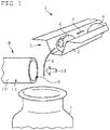
- a conveying section 1 with a conveying path 3 aligned in a conveying direction 2 is shown schematically.
- the conveyor track 3 there are two tablet-shaped products 4 which are conveyed along the conveying direction up to a front end 5 of the conveyor track 3 .
- the conveyor section 1 is designed as a vibration conveyor, so that the products 4 in the conveyor track 3 are conveyed by directed vibration movements of the conveyor section 1 in the conveying direction 2 up to the front end 5 of the conveyor track 3 .
- the tablet-shaped products 4 fall out of the row of conveyor belts and down along a fall trajectory 6 into a packaging container 7 arranged below the front end 5 of the conveyor track 3.
- the fall trajectory 6 corresponds to a trajectory of the products 4, which without external influence fall out of the front end 5 of the conveyor track 3 and then fall down due to gravity.
- a suction device 8 with a suction pipe 10 opening into a suction opening 9 is arranged laterally in the immediate vicinity of the fall trajectory 6 .
- a vacuum can be generated in the suction pipe 10 with a vacuum generating device, not shown, so that in a suction area in front of the suction opening 9 suction flow 11 directed into the suction pipe 10 is generated.
- the suction pipe 10 is arranged with its suction opening 9 on the fall trajectory 6 in such a way that the suction flow 11 flows through the fall trajectory 6 and a product 4 falling along the fall trajectory 6 is caught by the suction flow 11 and sucked through the suction opening 9 into the suction pipe 10.
- FIG 2 another variant of the method according to the invention is shown schematically.
- the suction pipe 10 with the suction opening 9 is brought up to the front end 5 of the conveyor track 3 immediately before the start of a suction process and arranged in such a way that the fall trajectory 6 of a falling product 4 would run through the suction opening 9 .
- the product 4 to be sorted out is already being conveyed in the direction of the suction opening 9 during conveyance in the conveyor track 3 .
- a suction section 12 adjoining the suction opening 9 has a small angle of less than 20° relative to a horizontal plane, or relative to the alignment of the conveyor track 3 .
- the suction pipe 10 with the suction opening 9 is removed from the front end 5 of the conveyor track 3 again.
- the subsequent product 4 can then fall undisturbed along the fall trajectory 6 and, for example, fall into a packaging container or a subsequent conveyor section.
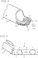
- FIG 3 a differently configured suction device 8 is shown.
- a cup-shaped collecting device 13 adjoining the suction opening 9 is formed on the suction tube 10 .
- the suction pipe 10 can be arranged with the collecting device 13 below the conveyor track 3 in such a way that the fall trajectory 6 opens into the collecting device 13 or the collecting device 13 passes through.
- the product 4 falling at the front end 5 along the fall trajectory 6 then falls into the collecting device 13 and can be sucked out of the collecting device 13 through the suction pipe 10 with a suction stream 11 with a low suction power.
- the suction pipe 10 with the collecting device 13 In order to prevent products 4 that are not to be sorted out from being impaired or even sorted out if they fall down along the fall trajectory 6, the suction pipe 10 with the collecting device 13 must be inserted into the fall trajectory 6 immediately before the start of a sorting process and then out of the fall trajectory 6 again be outsourced.
- the suction process can also only begin a little later, when the product 4 to be separated out has already been collected with the collecting device 13. If necessary, the suction process can only begin when the suction pipe 10 with the suction opening 9 and the collecting device 13 has already been removed from the fall trajectory 6 again.
- FIG 4 a differently configured collecting device 13 on the intake manifold 10 is shown as an example.
- the collecting device 13 has a grid 15 which is fixed to a frame 14 and forms an air-permeable flow opening 16 .
- the suction flow 11 can be drawn in through the grid 15 and thus through the flow opening formed by the grid 15, so that the suction flow 11 can be sucked in through the flow opening 16 into the suction pipe 10 almost unhindered and without turbulence.
- a product 4 lying on the grid 15 in the collecting device 13 can then be sucked off with a comparatively low suction power.
- the suction pipe 10 in the area of the suction opening 9 has a shape that is adapted to the shape of the front end 5 of the conveyor track 3 .
- a major portion of a cross-sectional area of the suction opening 9 covers the front end 5 of the conveyor track 3. Only a small portion of less than 20%, preferably less than 10% of the cross-sectional area of the suction opening 9 protrudes laterally along the conveyor track 3 and forms a stop surface 17, which can be used as a guide and positioning aid during displacement of the suction tube 10 before and after a suction process.
Landscapes
- Specific Conveyance Elements (AREA)
- Sorting Of Articles (AREA)
Claims (10)
- Procédé de séparation sélective de produits aptes à l'écoulement (4), qui sont transportés dans une direction de transport (2) le long d'une ligne de transport (1) dans une voie de transport (3), les produits transportés (4) étant évalués dans une section de contrôle de la ligne de transport (1) avec un appareil de contrôle et, dans une section de séparation agencée en aval le long de la ligne de transport (1), le produit (4) qui ne satisfait pas à un critère de contrôle prédéfinissable étant séparé et évacué de la voie de transport (3) avec un dispositif d'aspiration (8), par le fait que le dispositif d'aspiration (8) est agencé sur la ligne de transport (1) et un courant d'aspiration s'éloignant de la voie de transport (3) est produit pendant une durée d'aspiration prédéfinie afin d'aspirer le produit (4) hors de la voie de transport (3), caractérisé en ce qu'un tube d'aspiration (10) du dispositif d'aspiration (8) est agencé avec une ouverture d'aspiration (9) à une extrémité frontale (5) de la voie de transport (3), afin d'aspirer le produit (2) qui chute de la voie de transport (3) le long d'une trajectoire de chute (6) à l'extrémité frontale (5) de la voie de transport (3) à travers l'ouverture d'aspiration (9).
- Procédé selon la revendication 1, caractérisé en ce que le tube d'aspiration (10) est amené avec l'ouverture d'aspiration (9) à l'extrémité frontale (5) de la ligne de transport (1) avant une opération d'aspiration et est agencé avec l'ouverture d'aspiration (9) dans ou sur la trajectoire de chute (6) du produit (4) qui chute, afin d'aspirer le produit à séparer (4) pendant la chute le long de la trajectoire de chute (6), et en ce que le tube d'aspiration (10) avec l'ouverture d'aspiration (9) est éloigné de l'extrémité frontale (5) de la voie de transport (3) après une opération d'aspiration, afin de ne pas entraver la chute le long de la trajectoire de chute (6) d'un produit suivant dans la ligne de transport (1), qui ne doit pas être séparé.
- Procédé selon la revendication 1 ou la revendication 2, caractérisé en ce qu'un dispositif de collecte (13) adjacent à l'ouverture d'aspiration (9) est agencé sur le tube d'aspiration (10) pour le produit à séparer (4), et en ce que le dispositif de collecte (13) est agencé dans la trajectoire de chute (6) avant une opération d'aspiration, afin de collecter le produit (4) qui chute avec le dispositif de collecte (13), et en ce que le produit (4) collecté avec le dispositif de collecte (13) est ensuite aspiré à travers l'ouverture d'aspiration (9) .
- Procédé selon la revendication 3, caractérisé en ce que le dispositif de collecte (13) est déplacé par rapport à l'ouverture d'aspiration (9) après la collecte du produit (4) à séparer, afin de favoriser l'aspiration du produit (4) à travers l'ouverture d'aspiration (9).
- Procédé selon l'une quelconque des revendications précédentes, caractérisé en ce qu'une section d'aspiration (12) du tube d'aspiration (10) adjacente à l'ouverture d'aspiration (9) est orientée selon un angle inférieur à 45°, de préférence inférieur à 20°, par rapport à un plan horizontal pendant une opération d'aspiration.
- Procédé selon l'une quelconque des revendications 1, 2 ou 5, caractérisé en ce que l'ouverture d'aspiration (9) du tube d'aspiration (10) du dispositif d'aspiration (8) entoure au moins par sections l'extrémité frontale (5) de la voie de transport (3) pendant l'opération d'aspiration.
- Dispositif pour la séparation sélective de produits aptes à l'écoulement (4), comprenant une voie de transport (3) s'étendant dans une direction de transport (2) jusqu'à une extrémité frontale (5) d'une ligne de transport (1), et comprenant un dispositif d'aspiration (8) avec un tube d'aspiration (10) débouchant dans une ouverture d'aspiration (9), caractérisé en ce que le tube d'aspiration (10) est monté de manière déplaçable sur l'extrémité frontale (5) de la voie de transport (1), de telle sorte que le tube d'aspiration (10) peut être déplacé avec l'ouverture d'aspiration (9) en dessous d'un côté supérieur de la voie de transport (3) dans ou sur une trajectoire de chute (6) d'un produit (4) qui chute hors de la voie de transport (3) à l'extrémité frontale (5) et peut être éloigné de la trajectoire de chute (6) après la fin d'une opération d'aspiration.
- Dispositif selon la revendication 7, caractérisé en ce que un dispositif de collecte (13) adjacent à l'ouverture d'aspiration (9) pour le produit (4) à séparer est agencé sur le tube d'aspiration (10).
- Dispositif selon la revendication 8, caractérisé en ce que le dispositif de collecte (13) présente une zone de collecte en forme d'auge ou de cuvette pour le produit (4) à séparer.
- Dispositif selon la revendication 8 ou la revendication 9, caractérisé en ce que le dispositif de collecte (13) présente au moins une ouverture d'écoulement (16) perméable à l'air, à travers laquelle un courant d'aspiration (11) dirigé en direction de l'ouverture d'aspiration (9) du tube d'aspiration (10) peut passer au moins partiellement.
Applications Claiming Priority (2)
| Application Number | Priority Date | Filing Date | Title |
|---|---|---|---|
| DE102018120721.2A DE102018120721A1 (de) | 2018-08-24 | 2018-08-24 | Verfahren zum selektiven Aussondern von rieselfähigen Produkten |
| PCT/EP2019/072630 WO2020039087A1 (fr) | 2018-08-24 | 2019-08-23 | Procédé de mise au rebut sélective de produits coulants |
Publications (2)
| Publication Number | Publication Date |
|---|---|
| EP3840894A1 EP3840894A1 (fr) | 2021-06-30 |
| EP3840894B1 true EP3840894B1 (fr) | 2022-08-03 |
Family
ID=67928794
Family Applications (1)
| Application Number | Title | Priority Date | Filing Date |
|---|---|---|---|
| EP19766187.9A Active EP3840894B1 (fr) | 2018-08-24 | 2019-08-23 | Procédé et dispositif d'élimination sélective des produits apte à ruisseler |
Country Status (4)
| Country | Link |
|---|---|
| US (1) | US11577280B2 (fr) |
| EP (1) | EP3840894B1 (fr) |
| DE (1) | DE102018120721A1 (fr) |
| WO (1) | WO2020039087A1 (fr) |
Family Cites Families (8)
| Publication number | Priority date | Publication date | Assignee | Title |
|---|---|---|---|---|
| US3415368A (en) * | 1966-09-13 | 1968-12-10 | Ramsey Eng Co | Core handling device with air sorting system |
| DE4335156B4 (de) * | 1993-10-15 | 2005-08-25 | BüHLER GMBH | Regelvorrichtung für ein Mahlwerk |
| JP5568770B2 (ja) * | 2009-10-08 | 2014-08-13 | テクマン工業株式会社 | プラスチックペレット選別機 |
| US10016790B1 (en) * | 2010-08-17 | 2018-07-10 | K.B.C. Group, Inc. | Dual robotic sorting system and method |
| US20140250835A1 (en) * | 2013-03-05 | 2014-09-11 | Howmedica Osteonics Corp. | Process for removing contaminants from polymeric powders |
| EP2859963A1 (fr) * | 2013-10-11 | 2015-04-15 | Sikora Ag | Dispositif et procédé destinés à trier des produits en vrac |
| CN106000924A (zh) * | 2016-06-20 | 2016-10-12 | 合肥名德光电科技股份有限公司 | 一种吸气剔除式物料色选机 |
| JP6275911B1 (ja) * | 2017-10-02 | 2018-02-07 | 株式会社服部製作所 | 色彩選別機 |
-
2018
- 2018-08-24 DE DE102018120721.2A patent/DE102018120721A1/de not_active Withdrawn
-
2019
- 2019-08-23 US US17/270,290 patent/US11577280B2/en active Active
- 2019-08-23 EP EP19766187.9A patent/EP3840894B1/fr active Active
- 2019-08-23 WO PCT/EP2019/072630 patent/WO2020039087A1/fr not_active Ceased
Also Published As
| Publication number | Publication date |
|---|---|
| US11577280B2 (en) | 2023-02-14 |
| EP3840894A1 (fr) | 2021-06-30 |
| DE102018120721A1 (de) | 2020-02-27 |
| US20210252557A1 (en) | 2021-08-19 |
| WO2020039087A1 (fr) | 2020-02-27 |
Similar Documents
| Publication | Publication Date | Title |
|---|---|---|
| EP3898462B1 (fr) | Trieur transversal comprenant un dispositif d'enlèvement et procédé pour éloigner des marchandises mal positionnées sur un trieur transversal | |
| EP3315420B1 (fr) | Machine d'emballage par emboutissage | |
| EP0163043B1 (fr) | Dispositif d'amenée, dans des machines d'emballage, de petits produits pharmaceutiques, tels que tablettes, pilules, capsules, etc. | |
| EP3315423B1 (fr) | Machine d'emballage par emboutissage | |
| WO2016198610A1 (fr) | Dispositif de coupe de flans de tôle dans une bande de tôle | |
| WO2017207388A1 (fr) | Machine d'usinage par découpage d'une pièce et procédé d'évacuation de parties de pièces | |
| WO2011070065A1 (fr) | Dispositif de triage | |
| DE102016101027B4 (de) | Rundläufertablettenpresse | |
| EP3670399A1 (fr) | Transporteur en cascade et procédé de tri et de transport de fermetures de récipient | |
| EP4154721A1 (fr) | Dispositif et procédé de transport et d'évacuation de portions séparées d'aliments | |
| DE102018105269A1 (de) | Verpackungsvorrichtung für Artikel und Verfahren zum Bereitstellen von flächigen Verpackungszuschnitten für Artikel | |
| EP2859802B1 (fr) | Dispositif et procédé de transport et de tri d'articles à fumer | |
| EP3208001A1 (fr) | Séparateur pneumatique doté d'une triple séparation | |
| EP4601976A1 (fr) | Dispositif de transport et de séparation de pièces | |
| EP3840894B1 (fr) | Procédé et dispositif d'élimination sélective des produits apte à ruisseler | |
| DE102019207724A1 (de) | Befördern von traystapeln mit einer denester-einheit | |
| DE102016101028B4 (de) | Rundläufertablettenpresse | |
| DE102018124212A1 (de) | Förderstrecke für einen Transport einer Vielzahl von Artikeln und Verfahren zum Anpassen und/oder Betreiben einer Förderstrecke | |
| AT506149B1 (de) | Fördervorrichtung für kleinteile | |
| EP3840895B1 (fr) | Procédé d'élimination sélective des produits apte à ruisseler | |
| EP1062883A1 (fr) | Méthode et appareil pour fabriquer et/ou emballer des cigarettes | |
| EP2417860A1 (fr) | Dispositif et procédé de séparation de parties de balles d'un produit comprimé | |
| DE102016119833A1 (de) | Zusammenführungsvorrichtung und -verfahren | |
| DE68901692T2 (de) | Automatische vorrichtung zum entfernen von verschiedenen artikeln, insbesondere kapseln, tabletten und dragees aus in einem streifen ausgebildeten, angepassten hoheraeumen. | |
| DE102008058998B4 (de) | Verfahren zur Sichtung bzw. Klassifizierung von geschnittenem, pflanzlichen Schüttgut, insbesondere Tabak, sowie Vorrichtung zur Durchführung des Verfahrens |
Legal Events
| Date | Code | Title | Description |
|---|---|---|---|
| STAA | Information on the status of an ep patent application or granted ep patent |
Free format text: STATUS: UNKNOWN |
|
| STAA | Information on the status of an ep patent application or granted ep patent |
Free format text: STATUS: THE INTERNATIONAL PUBLICATION HAS BEEN MADE |
|
| PUAI | Public reference made under article 153(3) epc to a published international application that has entered the european phase |
Free format text: ORIGINAL CODE: 0009012 |
|
| STAA | Information on the status of an ep patent application or granted ep patent |
Free format text: STATUS: REQUEST FOR EXAMINATION WAS MADE |
|
| 17P | Request for examination filed |
Effective date: 20210312 |
|
| AK | Designated contracting states |
Kind code of ref document: A1 Designated state(s): AL AT BE BG CH CY CZ DE DK EE ES FI FR GB GR HR HU IE IS IT LI LT LU LV MC MK MT NL NO PL PT RO RS SE SI SK SM TR |
|
| DAV | Request for validation of the european patent (deleted) | ||
| DAX | Request for extension of the european patent (deleted) | ||
| GRAP | Despatch of communication of intention to grant a patent |
Free format text: ORIGINAL CODE: EPIDOSNIGR1 |
|
| STAA | Information on the status of an ep patent application or granted ep patent |
Free format text: STATUS: GRANT OF PATENT IS INTENDED |
|
| GRAS | Grant fee paid |
Free format text: ORIGINAL CODE: EPIDOSNIGR3 |
|
| INTG | Intention to grant announced |
Effective date: 20220322 |
|
| GRAA | (expected) grant |
Free format text: ORIGINAL CODE: 0009210 |
|
| STAA | Information on the status of an ep patent application or granted ep patent |
Free format text: STATUS: THE PATENT HAS BEEN GRANTED |
|
| AK | Designated contracting states |
Kind code of ref document: B1 Designated state(s): AL AT BE BG CH CY CZ DE DK EE ES FI FR GB GR HR HU IE IS IT LI LT LU LV MC MK MT NL NO PL PT RO RS SE SI SK SM TR |
|
| REG | Reference to a national code |
Ref country code: AT Ref legal event code: REF Ref document number: 1508310 Country of ref document: AT Kind code of ref document: T Effective date: 20220815 Ref country code: CH Ref legal event code: EP |
|
| REG | Reference to a national code |
Ref country code: DE Ref legal event code: R096 Ref document number: 502019005172 Country of ref document: DE |
|
| REG | Reference to a national code |
Ref country code: IE Ref legal event code: FG4D Free format text: LANGUAGE OF EP DOCUMENT: GERMAN |
|
| REG | Reference to a national code |
Ref country code: NL Ref legal event code: FP |
|
| REG | Reference to a national code |
Ref country code: LT Ref legal event code: MG9D |
|
| PG25 | Lapsed in a contracting state [announced via postgrant information from national office to epo] |
Ref country code: SE Free format text: LAPSE BECAUSE OF FAILURE TO SUBMIT A TRANSLATION OF THE DESCRIPTION OR TO PAY THE FEE WITHIN THE PRESCRIBED TIME-LIMIT Effective date: 20220803 Ref country code: RS Free format text: LAPSE BECAUSE OF FAILURE TO SUBMIT A TRANSLATION OF THE DESCRIPTION OR TO PAY THE FEE WITHIN THE PRESCRIBED TIME-LIMIT Effective date: 20220803 Ref country code: PT Free format text: LAPSE BECAUSE OF FAILURE TO SUBMIT A TRANSLATION OF THE DESCRIPTION OR TO PAY THE FEE WITHIN THE PRESCRIBED TIME-LIMIT Effective date: 20221205 Ref country code: NO Free format text: LAPSE BECAUSE OF FAILURE TO SUBMIT A TRANSLATION OF THE DESCRIPTION OR TO PAY THE FEE WITHIN THE PRESCRIBED TIME-LIMIT Effective date: 20221103 Ref country code: LV Free format text: LAPSE BECAUSE OF FAILURE TO SUBMIT A TRANSLATION OF THE DESCRIPTION OR TO PAY THE FEE WITHIN THE PRESCRIBED TIME-LIMIT Effective date: 20220803 Ref country code: LT Free format text: LAPSE BECAUSE OF FAILURE TO SUBMIT A TRANSLATION OF THE DESCRIPTION OR TO PAY THE FEE WITHIN THE PRESCRIBED TIME-LIMIT Effective date: 20220803 Ref country code: FI Free format text: LAPSE BECAUSE OF FAILURE TO SUBMIT A TRANSLATION OF THE DESCRIPTION OR TO PAY THE FEE WITHIN THE PRESCRIBED TIME-LIMIT Effective date: 20220803 Ref country code: ES Free format text: LAPSE BECAUSE OF FAILURE TO SUBMIT A TRANSLATION OF THE DESCRIPTION OR TO PAY THE FEE WITHIN THE PRESCRIBED TIME-LIMIT Effective date: 20220803 |
|
| PG25 | Lapsed in a contracting state [announced via postgrant information from national office to epo] |
Ref country code: PL Free format text: LAPSE BECAUSE OF FAILURE TO SUBMIT A TRANSLATION OF THE DESCRIPTION OR TO PAY THE FEE WITHIN THE PRESCRIBED TIME-LIMIT Effective date: 20220803 Ref country code: IS Free format text: LAPSE BECAUSE OF FAILURE TO SUBMIT A TRANSLATION OF THE DESCRIPTION OR TO PAY THE FEE WITHIN THE PRESCRIBED TIME-LIMIT Effective date: 20221203 Ref country code: HR Free format text: LAPSE BECAUSE OF FAILURE TO SUBMIT A TRANSLATION OF THE DESCRIPTION OR TO PAY THE FEE WITHIN THE PRESCRIBED TIME-LIMIT Effective date: 20220803 Ref country code: GR Free format text: LAPSE BECAUSE OF FAILURE TO SUBMIT A TRANSLATION OF THE DESCRIPTION OR TO PAY THE FEE WITHIN THE PRESCRIBED TIME-LIMIT Effective date: 20221104 |
|
| REG | Reference to a national code |
Ref country code: CH Ref legal event code: PL |
|
| PG25 | Lapsed in a contracting state [announced via postgrant information from national office to epo] |
Ref country code: SM Free format text: LAPSE BECAUSE OF FAILURE TO SUBMIT A TRANSLATION OF THE DESCRIPTION OR TO PAY THE FEE WITHIN THE PRESCRIBED TIME-LIMIT Effective date: 20220803 Ref country code: RO Free format text: LAPSE BECAUSE OF FAILURE TO SUBMIT A TRANSLATION OF THE DESCRIPTION OR TO PAY THE FEE WITHIN THE PRESCRIBED TIME-LIMIT Effective date: 20220803 Ref country code: LU Free format text: LAPSE BECAUSE OF NON-PAYMENT OF DUE FEES Effective date: 20220823 Ref country code: LI Free format text: LAPSE BECAUSE OF NON-PAYMENT OF DUE FEES Effective date: 20220831 Ref country code: DK Free format text: LAPSE BECAUSE OF FAILURE TO SUBMIT A TRANSLATION OF THE DESCRIPTION OR TO PAY THE FEE WITHIN THE PRESCRIBED TIME-LIMIT Effective date: 20220803 Ref country code: CZ Free format text: LAPSE BECAUSE OF FAILURE TO SUBMIT A TRANSLATION OF THE DESCRIPTION OR TO PAY THE FEE WITHIN THE PRESCRIBED TIME-LIMIT Effective date: 20220803 Ref country code: CH Free format text: LAPSE BECAUSE OF NON-PAYMENT OF DUE FEES Effective date: 20220831 |
|
| REG | Reference to a national code |
Ref country code: BE Ref legal event code: MM Effective date: 20220831 |
|
| REG | Reference to a national code |
Ref country code: DE Ref legal event code: R097 Ref document number: 502019005172 Country of ref document: DE |
|
| PG25 | Lapsed in a contracting state [announced via postgrant information from national office to epo] |
Ref country code: SK Free format text: LAPSE BECAUSE OF FAILURE TO SUBMIT A TRANSLATION OF THE DESCRIPTION OR TO PAY THE FEE WITHIN THE PRESCRIBED TIME-LIMIT Effective date: 20220803 Ref country code: MC Free format text: LAPSE BECAUSE OF FAILURE TO SUBMIT A TRANSLATION OF THE DESCRIPTION OR TO PAY THE FEE WITHIN THE PRESCRIBED TIME-LIMIT Effective date: 20220803 Ref country code: EE Free format text: LAPSE BECAUSE OF FAILURE TO SUBMIT A TRANSLATION OF THE DESCRIPTION OR TO PAY THE FEE WITHIN THE PRESCRIBED TIME-LIMIT Effective date: 20220803 |
|
| PLBE | No opposition filed within time limit |
Free format text: ORIGINAL CODE: 0009261 |
|
| STAA | Information on the status of an ep patent application or granted ep patent |
Free format text: STATUS: NO OPPOSITION FILED WITHIN TIME LIMIT |
|
| PG25 | Lapsed in a contracting state [announced via postgrant information from national office to epo] |
Ref country code: AL Free format text: LAPSE BECAUSE OF FAILURE TO SUBMIT A TRANSLATION OF THE DESCRIPTION OR TO PAY THE FEE WITHIN THE PRESCRIBED TIME-LIMIT Effective date: 20220803 |
|
| 26N | No opposition filed |
Effective date: 20230504 |
|
| PG25 | Lapsed in a contracting state [announced via postgrant information from national office to epo] |
Ref country code: IE Free format text: LAPSE BECAUSE OF NON-PAYMENT OF DUE FEES Effective date: 20220823 |
|
| PG25 | Lapsed in a contracting state [announced via postgrant information from national office to epo] |
Ref country code: SI Free format text: LAPSE BECAUSE OF FAILURE TO SUBMIT A TRANSLATION OF THE DESCRIPTION OR TO PAY THE FEE WITHIN THE PRESCRIBED TIME-LIMIT Effective date: 20220803 |
|
| PG25 | Lapsed in a contracting state [announced via postgrant information from national office to epo] |
Ref country code: BE Free format text: LAPSE BECAUSE OF NON-PAYMENT OF DUE FEES Effective date: 20220831 |
|
| PGFP | Annual fee paid to national office [announced via postgrant information from national office to epo] |
Ref country code: IT Payment date: 20230831 Year of fee payment: 5 |
|
| PGFP | Annual fee paid to national office [announced via postgrant information from national office to epo] |
Ref country code: FR Payment date: 20230821 Year of fee payment: 5 |
|
| GBPC | Gb: european patent ceased through non-payment of renewal fee |
Effective date: 20230823 |
|
| PG25 | Lapsed in a contracting state [announced via postgrant information from national office to epo] |
Ref country code: CY Free format text: LAPSE BECAUSE OF FAILURE TO SUBMIT A TRANSLATION OF THE DESCRIPTION OR TO PAY THE FEE WITHIN THE PRESCRIBED TIME-LIMIT Effective date: 20220803 |
|
| PG25 | Lapsed in a contracting state [announced via postgrant information from national office to epo] |
Ref country code: MK Free format text: LAPSE BECAUSE OF FAILURE TO SUBMIT A TRANSLATION OF THE DESCRIPTION OR TO PAY THE FEE WITHIN THE PRESCRIBED TIME-LIMIT Effective date: 20220803 Ref country code: HU Free format text: LAPSE BECAUSE OF FAILURE TO SUBMIT A TRANSLATION OF THE DESCRIPTION OR TO PAY THE FEE WITHIN THE PRESCRIBED TIME-LIMIT; INVALID AB INITIO Effective date: 20190823 |
|
| PG25 | Lapsed in a contracting state [announced via postgrant information from national office to epo] |
Ref country code: GB Free format text: LAPSE BECAUSE OF NON-PAYMENT OF DUE FEES Effective date: 20230823 |
|
| PG25 | Lapsed in a contracting state [announced via postgrant information from national office to epo] |
Ref country code: GB Free format text: LAPSE BECAUSE OF NON-PAYMENT OF DUE FEES Effective date: 20230823 Ref country code: BG Free format text: LAPSE BECAUSE OF FAILURE TO SUBMIT A TRANSLATION OF THE DESCRIPTION OR TO PAY THE FEE WITHIN THE PRESCRIBED TIME-LIMIT Effective date: 20220803 |
|
| PG25 | Lapsed in a contracting state [announced via postgrant information from national office to epo] |
Ref country code: MT Free format text: LAPSE BECAUSE OF FAILURE TO SUBMIT A TRANSLATION OF THE DESCRIPTION OR TO PAY THE FEE WITHIN THE PRESCRIBED TIME-LIMIT Effective date: 20220803 |
|
| PG25 | Lapsed in a contracting state [announced via postgrant information from national office to epo] |
Ref country code: IT Free format text: LAPSE BECAUSE OF NON-PAYMENT OF DUE FEES Effective date: 20240823 |
|
| PG25 | Lapsed in a contracting state [announced via postgrant information from national office to epo] |
Ref country code: FR Free format text: LAPSE BECAUSE OF NON-PAYMENT OF DUE FEES Effective date: 20240831 |
|
| REG | Reference to a national code |
Ref country code: AT Ref legal event code: MM01 Ref document number: 1508310 Country of ref document: AT Kind code of ref document: T Effective date: 20240823 |
|
| PG25 | Lapsed in a contracting state [announced via postgrant information from national office to epo] |
Ref country code: AT Free format text: LAPSE BECAUSE OF NON-PAYMENT OF DUE FEES Effective date: 20240823 |
|
| PG25 | Lapsed in a contracting state [announced via postgrant information from national office to epo] |
Ref country code: TR Free format text: LAPSE BECAUSE OF FAILURE TO SUBMIT A TRANSLATION OF THE DESCRIPTION OR TO PAY THE FEE WITHIN THE PRESCRIBED TIME-LIMIT Effective date: 20220803 |
|
| PGFP | Annual fee paid to national office [announced via postgrant information from national office to epo] |
Ref country code: NL Payment date: 20260226 Year of fee payment: 7 |
|
| PGFP | Annual fee paid to national office [announced via postgrant information from national office to epo] |
Ref country code: DE Payment date: 20260225 Year of fee payment: 7 |
|
| PGFP | Annual fee paid to national office [announced via postgrant information from national office to epo] |
Ref country code: AT Payment date: 20260410 Year of fee payment: 5 |