EP3208001A1 - Séparateur pneumatique doté d'une triple séparation - Google Patents
Séparateur pneumatique doté d'une triple séparation Download PDFInfo
- Publication number
- EP3208001A1 EP3208001A1 EP17156885.0A EP17156885A EP3208001A1 EP 3208001 A1 EP3208001 A1 EP 3208001A1 EP 17156885 A EP17156885 A EP 17156885A EP 3208001 A1 EP3208001 A1 EP 3208001A1
- Authority
- EP
- European Patent Office
- Prior art keywords
- conveyor belt
- air classifier
- mixture
- walls
- section
- Prior art date
- Legal status (The legal status is an assumption and is not a legal conclusion. Google has not performed a legal analysis and makes no representation as to the accuracy of the status listed.)
- Granted
Links
Images
Classifications
-
- B—PERFORMING OPERATIONS; TRANSPORTING
- B07—SEPARATING SOLIDS FROM SOLIDS; SORTING
- B07B—SEPARATING SOLIDS FROM SOLIDS BY SIEVING, SCREENING, SIFTING OR BY USING GAS CURRENTS; SEPARATING BY OTHER DRY METHODS APPLICABLE TO BULK MATERIAL, e.g. LOOSE ARTICLES FIT TO BE HANDLED LIKE BULK MATERIAL
- B07B9/00—Combinations of apparatus for screening or sifting or for separating solids from solids using gas currents; General arrangement of plant, e.g. flow sheets
- B07B9/02—Combinations of similar or different apparatus for separating solids from solids using gas currents
-
- B—PERFORMING OPERATIONS; TRANSPORTING
- B07—SEPARATING SOLIDS FROM SOLIDS; SORTING
- B07B—SEPARATING SOLIDS FROM SOLIDS BY SIEVING, SCREENING, SIFTING OR BY USING GAS CURRENTS; SEPARATING BY OTHER DRY METHODS APPLICABLE TO BULK MATERIAL, e.g. LOOSE ARTICLES FIT TO BE HANDLED LIKE BULK MATERIAL
- B07B4/00—Separating solids from solids by subjecting their mixture to gas currents
- B07B4/02—Separating solids from solids by subjecting their mixture to gas currents while the mixtures fall
- B07B4/025—Separating solids from solids by subjecting their mixture to gas currents while the mixtures fall the material being slingered or fled out horizontally before falling, e.g. by dispersing elements
-
- B—PERFORMING OPERATIONS; TRANSPORTING
- B07—SEPARATING SOLIDS FROM SOLIDS; SORTING
- B07B—SEPARATING SOLIDS FROM SOLIDS BY SIEVING, SCREENING, SIFTING OR BY USING GAS CURRENTS; SEPARATING BY OTHER DRY METHODS APPLICABLE TO BULK MATERIAL, e.g. LOOSE ARTICLES FIT TO BE HANDLED LIKE BULK MATERIAL
- B07B4/00—Separating solids from solids by subjecting their mixture to gas currents
- B07B4/08—Separating solids from solids by subjecting their mixture to gas currents while the mixtures are supported by sieves, screens, or like mechanical elements
-
- B—PERFORMING OPERATIONS; TRANSPORTING
- B03—SEPARATION OF SOLID MATERIALS USING LIQUIDS OR USING PNEUMATIC TABLES OR JIGS; MAGNETIC OR ELECTROSTATIC SEPARATION OF SOLID MATERIALS FROM SOLID MATERIALS OR FLUIDS; SEPARATION BY HIGH-VOLTAGE ELECTRIC FIELDS
- B03B—SEPARATING SOLID MATERIALS USING LIQUIDS OR USING PNEUMATIC TABLES OR JIGS
- B03B9/00—General arrangement of separating plant, e.g. flow sheets
- B03B9/06—General arrangement of separating plant, e.g. flow sheets specially adapted for refuse
-
- Y—GENERAL TAGGING OF NEW TECHNOLOGICAL DEVELOPMENTS; GENERAL TAGGING OF CROSS-SECTIONAL TECHNOLOGIES SPANNING OVER SEVERAL SECTIONS OF THE IPC; TECHNICAL SUBJECTS COVERED BY FORMER USPC CROSS-REFERENCE ART COLLECTIONS [XRACs] AND DIGESTS
- Y02—TECHNOLOGIES OR APPLICATIONS FOR MITIGATION OR ADAPTATION AGAINST CLIMATE CHANGE
- Y02W—CLIMATE CHANGE MITIGATION TECHNOLOGIES RELATED TO WASTEWATER TREATMENT OR WASTE MANAGEMENT
- Y02W30/00—Technologies for solid waste management
- Y02W30/50—Reuse, recycling or recovery technologies
- Y02W30/52—Mechanical processing of waste for the recovery of materials, e.g. crushing, shredding, separation or disassembly
Definitions
- the invention relates to an air classifier according to the preamble of claim 1.
- the invention has for its object to improve a generic air classifier to the effect that this enables the separation of lighter components from the crop mixture with the highest possible separation efficiency.
- the invention proposes to guide the conveyor belt over a kink point and to guide it further angled downwards behind the kink point.
- this may mean that the second section is horizontal behind the kink, or also upwards, but less steeply upward than the first section.
- first section of the conveyor belt is accordingly proposed, according to the second section behind the kink point steeper down to lead than the first section.
- the transition from the first to the second section is deliberately not slow, in a wide radius, but rather in a sharp as possible kink, so that at a corresponding speed of the conveyor belt, the crop mix stands out briefly from the conveyor belt. In this way, the air flow can not only attack on the upper surface of the crop mixture, but also below the crop mixture, so that in this way a higher proportion of the lighter Guts from the crop mixture with the air flow transported to the top and can be separated from the crop mixture.
- the invention is based on the consideration that due to the different pitch parabolas, the heavier material usually falls earlier on the stripping band than the lighter material when the crop mixture leaves the first classifier stage. This has the consequence that the lighter material is above the heavier, before the crop mixture reaches the second separation stage, so that the subsequent material separation in the second classifier stage is simplified.
- the proposed combination of the two systems is particularly advantageous because not only a total of a separation of the original material mixture into more different fractions takes place, but also a kind of synergy effect is achieved by already carried out by the first separator stage a pre-separation in two layers on the draw-off with the lighter good at the top and the heavier good at the bottom.
- the good As a lighter Good is understood in the sense of the present proposal, the good, which can be carried by an air flow rather against gravity upwards than the other, accordingly heavier Good of the good mixture.
- this designation is a common good in practice, colloquial designation that neither the actual piece weight of a particular particle concerns nor its specific gravity, so based on a defined volume.
- the mentioned plastic films may have a comparatively higher weight than other constituents of the good mixture, and their plastic material may possibly have a higher specific gravity (density) have as other components of the good mixture;
- density specific gravity
- due to their comparatively large-scale design they can be easily separated from the air flow from the crop mixture, so that they are accordingly both colloquially and in the context of the present proposal as the lighter Good.
- the blower can be configured as a suction fan and arranged above the conveyor belt.
- This not only allows a comparatively simple air flow and accordingly simple structural design of the air classifier, but also allows the retrofitting of existing systems with the proposal according to designed separation stage.
- the area in which the blower acts on the material mixture is also referred to as blower location, and in the embodiment as a suction blower, this point can accordingly be referred to as extraction point, at which namely the light components are sucked from the conveyor belt.
- two aprons can be arranged in front of and behind the kink point, which extend from above to near the conveyor belt, so that an air channel between these two aprons results, which channels the upwardly flowing air flow and supports in this way that of the air flow entrained lighter components can be performed together with the air flow and separated from the rest of the good mixture. Due to their mobility or deformability, the aprons make it possible to avoid larger constituents of the crop mixture, so that these constituents do not lead to a blockage and can accumulate, for example, in front of such apron.
- a hood-like housing with walls can allow the channeling of the air flow.
- the walls can be made of a solid material, such as sheet metal.
- a fast mobility of the walls at the same time particularly robust and reliable construction can be made possible if the walls are each connected by winding tapes with a winding axis, so that depending on the direction of rotation of the winding axis, the wall connected thereto can be raised or lowered.
- a need-based control of the walls can be done for example by means of a flap which is mounted pendulum and is arranged above the conveyor belt, so that the correspondingly large components of the crop mix get against this so-called sensor flap and deflect it.
- a photoelectric barrier false alarms are avoided by the greater inertia of the sensor flap, as could otherwise be done, for example, by lightweight materials such as films.
- the wind sifter designed according to the proposal can be arranged as a second separating stage behind a first separating stage.
- a mixture of three different fractions, called a coarse mixture is fed by means of a feed belt to this first separation stage.
- the first separation stage has a drum whose upper drum circumference rotates in the conveying direction of the feed belt. Due to the running speed of the feed belt lighter components of the Rough mixture to the drum carried, while heavier components fall down as the first fraction to be separated between the feed belt and the drum.
- a so-called support blower introduces air flow into this nip between feed belt and drum, this air flow being directed upwards and thus preventing the lighter material from the coarse mixture from falling down together with the heavy components in the nip between feed belt and drum.
- This lighter portion of the coarse mixture is then conveyed on the upper drum circumference and falls by gravity down beyond the feed belt from the drum circumference down to the conveyor belt of the proposed air classifier.
- the second separation stage of the entire air classifier is provided around the kink of the conveyor belt around the separation stage, so that with the proposal according to designed air classifier an original coarse mixture can be separated into a total of three fractions.
- it may be provided to set up a suction point with the blower mentioned there on the conveyor belt, where this has no kink, but is rectilinear.
- it may be provided to channel the air flow generated by the suction fan by means of a pipe, a hood-like housing or the like.
- the wall of the tube or the housing ends at a certain distance above the conveyor belt, so that a gap between the wall and the conveyor belt remains.
- the extent of this gap is determined. If, in certain applications, the gap can be made comparatively small, the suction power of the fan may possibly be sufficient to produce the desired separation effect, even without the aforementioned kink in the conveyor belt.
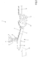
- a total of 1 air separator is designated, which has a conveyor belt 2, which promotes a good mixture 3 upwards.
- the product mixture 3 contains lighter and heavier components.
- the conveyor belt 2 has a first section 4, which extends obliquely upward and merges at a kink 5 in a second section 6, which runs less steeply upwards, runs horizontally in the illustrated embodiment. Due to the running speed of the conveyor belt 2, the crop mixture 3 briefly lifts off the conveyor belt 2 shortly behind the kink point 5, before it then rests again on the conveyor belt 2, namely on the second section 6. In the area where the crop mixture 3 lifts off the conveyor belt 2, air can also pass under the crop mixture 3 or in the crop mixture 3. In this case, a fan 7 is indicated above the kink point 5, which produces an indicated by arrows, upward air flow, the lighter Good 8 transported from the crop 3 upwards. In this case, a real flow channel is created by that according to Fig. 1 in front of and behind the kink 5 hang two aprons 9 from above.
- the previously described plant parts of the air classifier 1 serve as a second separation stage to separate medium good Good mix 3 from the lighter Good 8.
- a first separation stage which has a feed belt 11, which introduces a so-called coarse mixture.
- the coarse mixture contains the one hand, the entire crop 3, and also still coarse ingredients that are referred to as heavy goods.
- the feed belt 11 ends at a distance in front of a drum 12 whose upper drum circumference rotates in the conveying direction of the feed belt 11. Heavy components fall down into the gap, which results from the distance between feed belt 11 and drum 12.
- the lighter, remaining components of the coarse mixture, namely the product mixture 3 reach the upper area of the drum circumference, which is caused not only by the running speed of the feed belt 11 and the positioning of the feed belt 11 with respect to the drum 12, but also by a support fan 14 is supported, which blows an upwardly directed air flow in the gap between feed belt 11 and drum 12.
- Fig. 1 For this reason, two skirts 9 are provided for limiting the flow channel.
- the flexibility or mobility of the two skirts 9 allows them to avoid components of the crop mixture 3 by the skirts 9 are pushed out of the way of these components.
- the aprons 9 are accordingly passively movable and are moved by the contact with these to large components.
- the fan 7 is arranged within a hood-like housing indicated purely schematically, which is open at the bottom and otherwise has solid walls.
- the blower air and the components of the product mixture 3 transported by it are guided upwards or laterally out of the housing by means of an outlet opening.
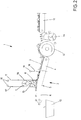
- the associated wall 15 can be selectively raised or lowered.
- This in Fig. 2 schematically indicated construction represents a robust and reliable way, the walls 15 within a short time and possibly only for to raise and lower a short period of time from its normal position shown. Deviating other technical configurations to adjustably store the walls 15 in height, however, are also possible and known to those skilled in the art, so that these variants need not be discussed in more detail.
- a sensor which comprises a pendulum mounted sensor flap 18 in the illustrated embodiment, which depends from a horizontal axis 19. Supported by its own weight, and optionally by a spring, the sensor flap 18 endeavors to automatically assume this downwardly suspended normal position.
- the resistance against which the sensor flap 18 can be deflected from its normal position and pivoted about the axis 19, can be influenced by the weight of the sensor flap 18, by the strength of said spring, and / or by a counterweight located beyond the axis 19.
- the sensor flap 18 terminates at a distance above the conveyor belt 2, which corresponds to the gap between the walls 15 and the conveyor belt 2. If too large components of the product mixture 3 against the sensor flap 18, namely components that are higher than the mentioned gap, so the pendulum suspended sensor flap 18 is deflected by these components from their hanging down normal position.
- This movement of the sensor flap 18 is detected by means of a sensor.
- a sensor signal output from this sensor is processed in a plant control, and the plant controller in turn drives the winding axes 16 so that the two walls 15 are raised for a short period of time. This period of time is determined so that the too large part of the crop mixture 3 can pass through the suction point and in the conveying direction of the conveyor belt 2 behind the rear wall 15th is located, so according to Fig. 2 left of the left wall 15. After this component has passed the suction, the walls 15 are lowered again.
- a control can be advantageously provided that the walls 15 are always raised only by the lowest possible level. In this way, the highest possible efficiency of the suction device is ensured by the gap between the two walls 15 and the conveyor belt 2 is always kept as small as possible. For example, based on the angle by which the sensor flap 18 is deflected, the extent to which the walls 15 are raised can be determined. Larger objects deflect the sensor flap 18 at a greater angle from its downward-hanging normal position than smaller objects. Accordingly, the walls 15 are raised higher to allow these larger objects to pass through than smaller to large objects.
- the sensor device with the sensor flap 18 does not interact with a system control, but directly serves as a switch for the winding axes 16.
- the switch namely by corresponding deflection of the sensor flap 18, the walls 15 are raised by means of the winding axes 16 for a predetermined period of time and lowered again after this time in this embodiment.
Landscapes
- Engineering & Computer Science (AREA)
- Mechanical Engineering (AREA)
- Combined Means For Separation Of Solids (AREA)
- Sorting Of Articles (AREA)
Priority Applications (1)
| Application Number | Priority Date | Filing Date | Title |
|---|---|---|---|
| PL17156885T PL3208001T3 (pl) | 2016-02-18 | 2017-02-20 | Klasyfikator powietrzny |
Applications Claiming Priority (1)
| Application Number | Priority Date | Filing Date | Title |
|---|---|---|---|
| DE202016100858.1U DE202016100858U1 (de) | 2016-02-18 | 2016-02-18 | Windsichter mit Dreifachtrennung |
Publications (2)
| Publication Number | Publication Date |
|---|---|
| EP3208001A1 true EP3208001A1 (fr) | 2017-08-23 |
| EP3208001B1 EP3208001B1 (fr) | 2019-08-07 |
Family
ID=56233665
Family Applications (1)
| Application Number | Title | Priority Date | Filing Date |
|---|---|---|---|
| EP17156885.0A Active EP3208001B1 (fr) | 2016-02-18 | 2017-02-20 | Séparateur pneumatique doté d'une triple séparation |
Country Status (3)
| Country | Link |
|---|---|
| EP (1) | EP3208001B1 (fr) |
| DE (1) | DE202016100858U1 (fr) |
| PL (1) | PL3208001T3 (fr) |
Cited By (4)
| Publication number | Priority date | Publication date | Assignee | Title |
|---|---|---|---|---|
| CN113490426A (zh) * | 2019-03-01 | 2021-10-08 | 格立莫农业机械制造有限两合公司 | 分离设备 |
| CN114273221A (zh) * | 2021-12-27 | 2022-04-05 | 瑞泰环保装备有限公司 | 分散型风选机 |
| CN114289310A (zh) * | 2021-12-24 | 2022-04-08 | 江苏凯富新材料科技有限公司 | 一种生物基材料用智能输送分拣装置 |
| CN118788592A (zh) * | 2024-07-26 | 2024-10-18 | 苏州嘉诺环境科技股份有限公司 | 一种多级风选设备 |
Families Citing this family (1)
| Publication number | Priority date | Publication date | Assignee | Title |
|---|---|---|---|---|
| DE202016102456U1 (de) | 2016-05-09 | 2016-07-01 | WESTERIA Fördertechnik GmbH | Semimobile Sichter-Anlage |
Citations (6)
| Publication number | Priority date | Publication date | Assignee | Title |
|---|---|---|---|---|
| US1593729A (en) * | 1924-12-20 | 1926-07-27 | Albert H Stebbins | Classifier |
| JPS62212287A (ja) * | 1986-03-12 | 1987-09-18 | 株式会社日本製鋼所 | 堆肥化処理装置の異物除去装置 |
| EP0546442A2 (fr) * | 1991-12-10 | 1993-06-16 | Hans Schmitt | Dispositif pour la séparation d'un mélange de matières de poids spécifiques différents |
| CN1724179A (zh) * | 2004-07-23 | 2006-01-25 | 张宏安 | 橡胶粉末筛选机 |
| US20140166552A1 (en) * | 2012-12-13 | 2014-06-19 | Laitram, L.L.C. | Air separator with plenum |
| KR20150118382A (ko) * | 2014-04-14 | 2015-10-22 | (유)금강환경 | 이송물의 이물질 분리장치 |
-
2016
- 2016-02-18 DE DE202016100858.1U patent/DE202016100858U1/de not_active Expired - Lifetime
-
2017
- 2017-02-20 PL PL17156885T patent/PL3208001T3/pl unknown
- 2017-02-20 EP EP17156885.0A patent/EP3208001B1/fr active Active
Patent Citations (6)
| Publication number | Priority date | Publication date | Assignee | Title |
|---|---|---|---|---|
| US1593729A (en) * | 1924-12-20 | 1926-07-27 | Albert H Stebbins | Classifier |
| JPS62212287A (ja) * | 1986-03-12 | 1987-09-18 | 株式会社日本製鋼所 | 堆肥化処理装置の異物除去装置 |
| EP0546442A2 (fr) * | 1991-12-10 | 1993-06-16 | Hans Schmitt | Dispositif pour la séparation d'un mélange de matières de poids spécifiques différents |
| CN1724179A (zh) * | 2004-07-23 | 2006-01-25 | 张宏安 | 橡胶粉末筛选机 |
| US20140166552A1 (en) * | 2012-12-13 | 2014-06-19 | Laitram, L.L.C. | Air separator with plenum |
| KR20150118382A (ko) * | 2014-04-14 | 2015-10-22 | (유)금강환경 | 이송물의 이물질 분리장치 |
Cited By (5)
| Publication number | Priority date | Publication date | Assignee | Title |
|---|---|---|---|---|
| CN113490426A (zh) * | 2019-03-01 | 2021-10-08 | 格立莫农业机械制造有限两合公司 | 分离设备 |
| CN113490426B (zh) * | 2019-03-01 | 2023-02-17 | 格立莫农业机械制造有限两合公司 | 分离设备 |
| CN114289310A (zh) * | 2021-12-24 | 2022-04-08 | 江苏凯富新材料科技有限公司 | 一种生物基材料用智能输送分拣装置 |
| CN114273221A (zh) * | 2021-12-27 | 2022-04-05 | 瑞泰环保装备有限公司 | 分散型风选机 |
| CN118788592A (zh) * | 2024-07-26 | 2024-10-18 | 苏州嘉诺环境科技股份有限公司 | 一种多级风选设备 |
Also Published As
| Publication number | Publication date |
|---|---|
| DE202016100858U1 (de) | 2016-06-08 |
| EP3208001B1 (fr) | 2019-08-07 |
| PL3208001T3 (pl) | 2020-03-31 |
Similar Documents
| Publication | Publication Date | Title |
|---|---|---|
| EP3208001B1 (fr) | Séparateur pneumatique doté d'une triple séparation | |
| EP3248914B1 (fr) | Glissière pour marchandise de détail et procédé d'utilisation d'une telle glissière | |
| EP2714370B1 (fr) | Procédé et dispositif permettant le transport d'objets vers une station | |
| EP2986543B1 (fr) | Séparation de paquets | |
| CH635692A5 (de) | Einrichtung zum sammeln und stapeln von fotografischen papierbildern. | |
| DE10141375C1 (de) | Vorrichtung zum Trennen von Sendungen in Dickenklassen | |
| EP0635430B1 (fr) | Dispositif pour alimenter une installation de tri de déchets avec les contenus de sacs-poubelles | |
| DE202008001933U1 (de) | Windsichteranlage | |
| EP3677349B1 (fr) | Procédé et dispositif de séparation des pièces longues | |
| AT504639B1 (de) | Mülltrennvorrichtung | |
| DE2714962A1 (de) | Verfahren und vorrichtung zum abtransport und zerkleinern von randstreifen | |
| EP2342981B1 (fr) | Retrait de papier dans un pot de transport oscillant de l'industrie de traitement du tabac | |
| DE202010006744U1 (de) | Sortiermaschine zum schonenden Sortieren stoßgefährdeter Knollengewächse nach bestimmten Größenmaßen | |
| DE102004040100B4 (de) | Verfahren und Vorrichtung zum Sortieren von Postsendungen | |
| DE2837037C2 (de) | Drehtrommel-Luftstrom-Sortiervorrichtung zum Trennen von Feststoffgemischen wie Müll und dergleichen | |
| EP1105222B1 (fr) | Dispositif permettant de trier des melanges de materiaux de valeur | |
| DE10148226C1 (de) | Vorrichtung zum Trennen von flachen Sendungen in Dickenklassen | |
| DE4413288C2 (de) | Vorrichtung zur Selektion von Bauschutt | |
| DE102008058998B4 (de) | Verfahren zur Sichtung bzw. Klassifizierung von geschnittenem, pflanzlichen Schüttgut, insbesondere Tabak, sowie Vorrichtung zur Durchführung des Verfahrens | |
| EP4076775B1 (fr) | Dispositif et procédé pour le triage d'un mélange de matières | |
| DE3423866C2 (de) | Vorrichtung zum Abtrennen nicht magnetisierbarer elektrisch leitfähiger Metallteile aus einem Feststoffgemisch | |
| WO1995007769A1 (fr) | Dispositif pour traiter des melanges de produits recyclables | |
| EP4556128B1 (fr) | Dispositif de tri pour séparer des composants d'un flux de matière et installation équipée correspondante et procédé | |
| EP2628552B1 (fr) | Dispositif de tri et de transport contrôlé | |
| EP3651563B1 (fr) | Dispositif permettant d'empêcher toute accumulation de fanes et machine de récolte associée |
Legal Events
| Date | Code | Title | Description |
|---|---|---|---|
| PUAI | Public reference made under article 153(3) epc to a published international application that has entered the european phase |
Free format text: ORIGINAL CODE: 0009012 |
|
| STAA | Information on the status of an ep patent application or granted ep patent |
Free format text: STATUS: THE APPLICATION HAS BEEN PUBLISHED |
|
| AK | Designated contracting states |
Kind code of ref document: A1 Designated state(s): AL AT BE BG CH CY CZ DE DK EE ES FI FR GB GR HR HU IE IS IT LI LT LU LV MC MK MT NL NO PL PT RO RS SE SI SK SM TR |
|
| AX | Request for extension of the european patent |
Extension state: BA ME |
|
| STAA | Information on the status of an ep patent application or granted ep patent |
Free format text: STATUS: REQUEST FOR EXAMINATION WAS MADE |
|
| 17P | Request for examination filed |
Effective date: 20180222 |
|
| RBV | Designated contracting states (corrected) |
Designated state(s): AL AT BE BG CH CY CZ DE DK EE ES FI FR GB GR HR HU IE IS IT LI LT LU LV MC MK MT NL NO PL PT RO RS SE SI SK SM TR |
|
| GRAP | Despatch of communication of intention to grant a patent |
Free format text: ORIGINAL CODE: EPIDOSNIGR1 |
|
| STAA | Information on the status of an ep patent application or granted ep patent |
Free format text: STATUS: GRANT OF PATENT IS INTENDED |
|
| INTG | Intention to grant announced |
Effective date: 20190311 |
|
| GRAS | Grant fee paid |
Free format text: ORIGINAL CODE: EPIDOSNIGR3 |
|
| GRAA | (expected) grant |
Free format text: ORIGINAL CODE: 0009210 |
|
| STAA | Information on the status of an ep patent application or granted ep patent |
Free format text: STATUS: THE PATENT HAS BEEN GRANTED |
|
| AK | Designated contracting states |
Kind code of ref document: B1 Designated state(s): AL AT BE BG CH CY CZ DE DK EE ES FI FR GB GR HR HU IE IS IT LI LT LU LV MC MK MT NL NO PL PT RO RS SE SI SK SM TR |
|
| REG | Reference to a national code |
Ref country code: GB Ref legal event code: FG4D Free format text: NOT ENGLISH |
|
| REG | Reference to a national code |
Ref country code: CH Ref legal event code: EP Ref country code: AT Ref legal event code: REF Ref document number: 1163029 Country of ref document: AT Kind code of ref document: T Effective date: 20190815 |
|
| REG | Reference to a national code |
Ref country code: DE Ref legal event code: R096 Ref document number: 502017001918 Country of ref document: DE |
|
| REG | Reference to a national code |
Ref country code: IE Ref legal event code: FG4D Free format text: LANGUAGE OF EP DOCUMENT: GERMAN |
|
| REG | Reference to a national code |
Ref country code: NL Ref legal event code: MP Effective date: 20190807 |
|
| REG | Reference to a national code |
Ref country code: LT Ref legal event code: MG4D |
|
| PG25 | Lapsed in a contracting state [announced via postgrant information from national office to epo] |
Ref country code: FI Free format text: LAPSE BECAUSE OF FAILURE TO SUBMIT A TRANSLATION OF THE DESCRIPTION OR TO PAY THE FEE WITHIN THE PRESCRIBED TIME-LIMIT Effective date: 20190807 Ref country code: NL Free format text: LAPSE BECAUSE OF FAILURE TO SUBMIT A TRANSLATION OF THE DESCRIPTION OR TO PAY THE FEE WITHIN THE PRESCRIBED TIME-LIMIT Effective date: 20190807 Ref country code: HR Free format text: LAPSE BECAUSE OF FAILURE TO SUBMIT A TRANSLATION OF THE DESCRIPTION OR TO PAY THE FEE WITHIN THE PRESCRIBED TIME-LIMIT Effective date: 20190807 Ref country code: LT Free format text: LAPSE BECAUSE OF FAILURE TO SUBMIT A TRANSLATION OF THE DESCRIPTION OR TO PAY THE FEE WITHIN THE PRESCRIBED TIME-LIMIT Effective date: 20190807 Ref country code: PT Free format text: LAPSE BECAUSE OF FAILURE TO SUBMIT A TRANSLATION OF THE DESCRIPTION OR TO PAY THE FEE WITHIN THE PRESCRIBED TIME-LIMIT Effective date: 20191209 Ref country code: SE Free format text: LAPSE BECAUSE OF FAILURE TO SUBMIT A TRANSLATION OF THE DESCRIPTION OR TO PAY THE FEE WITHIN THE PRESCRIBED TIME-LIMIT Effective date: 20190807 Ref country code: BG Free format text: LAPSE BECAUSE OF FAILURE TO SUBMIT A TRANSLATION OF THE DESCRIPTION OR TO PAY THE FEE WITHIN THE PRESCRIBED TIME-LIMIT Effective date: 20191107 Ref country code: NO Free format text: LAPSE BECAUSE OF FAILURE TO SUBMIT A TRANSLATION OF THE DESCRIPTION OR TO PAY THE FEE WITHIN THE PRESCRIBED TIME-LIMIT Effective date: 20191107 |
|
| PG25 | Lapsed in a contracting state [announced via postgrant information from national office to epo] |
Ref country code: IS Free format text: LAPSE BECAUSE OF FAILURE TO SUBMIT A TRANSLATION OF THE DESCRIPTION OR TO PAY THE FEE WITHIN THE PRESCRIBED TIME-LIMIT Effective date: 20191207 Ref country code: GR Free format text: LAPSE BECAUSE OF FAILURE TO SUBMIT A TRANSLATION OF THE DESCRIPTION OR TO PAY THE FEE WITHIN THE PRESCRIBED TIME-LIMIT Effective date: 20191108 Ref country code: RS Free format text: LAPSE BECAUSE OF FAILURE TO SUBMIT A TRANSLATION OF THE DESCRIPTION OR TO PAY THE FEE WITHIN THE PRESCRIBED TIME-LIMIT Effective date: 20190807 Ref country code: LV Free format text: LAPSE BECAUSE OF FAILURE TO SUBMIT A TRANSLATION OF THE DESCRIPTION OR TO PAY THE FEE WITHIN THE PRESCRIBED TIME-LIMIT Effective date: 20190807 Ref country code: AL Free format text: LAPSE BECAUSE OF FAILURE TO SUBMIT A TRANSLATION OF THE DESCRIPTION OR TO PAY THE FEE WITHIN THE PRESCRIBED TIME-LIMIT Effective date: 20190807 |
|
| PG25 | Lapsed in a contracting state [announced via postgrant information from national office to epo] |
Ref country code: TR Free format text: LAPSE BECAUSE OF FAILURE TO SUBMIT A TRANSLATION OF THE DESCRIPTION OR TO PAY THE FEE WITHIN THE PRESCRIBED TIME-LIMIT Effective date: 20190807 |
|
| PG25 | Lapsed in a contracting state [announced via postgrant information from national office to epo] |
Ref country code: EE Free format text: LAPSE BECAUSE OF FAILURE TO SUBMIT A TRANSLATION OF THE DESCRIPTION OR TO PAY THE FEE WITHIN THE PRESCRIBED TIME-LIMIT Effective date: 20190807 Ref country code: DK Free format text: LAPSE BECAUSE OF FAILURE TO SUBMIT A TRANSLATION OF THE DESCRIPTION OR TO PAY THE FEE WITHIN THE PRESCRIBED TIME-LIMIT Effective date: 20190807 Ref country code: RO Free format text: LAPSE BECAUSE OF FAILURE TO SUBMIT A TRANSLATION OF THE DESCRIPTION OR TO PAY THE FEE WITHIN THE PRESCRIBED TIME-LIMIT Effective date: 20190807 |
|
| PG25 | Lapsed in a contracting state [announced via postgrant information from national office to epo] |
Ref country code: SM Free format text: LAPSE BECAUSE OF FAILURE TO SUBMIT A TRANSLATION OF THE DESCRIPTION OR TO PAY THE FEE WITHIN THE PRESCRIBED TIME-LIMIT Effective date: 20190807 Ref country code: SK Free format text: LAPSE BECAUSE OF FAILURE TO SUBMIT A TRANSLATION OF THE DESCRIPTION OR TO PAY THE FEE WITHIN THE PRESCRIBED TIME-LIMIT Effective date: 20190807 Ref country code: CZ Free format text: LAPSE BECAUSE OF FAILURE TO SUBMIT A TRANSLATION OF THE DESCRIPTION OR TO PAY THE FEE WITHIN THE PRESCRIBED TIME-LIMIT Effective date: 20190807 Ref country code: IS Free format text: LAPSE BECAUSE OF FAILURE TO SUBMIT A TRANSLATION OF THE DESCRIPTION OR TO PAY THE FEE WITHIN THE PRESCRIBED TIME-LIMIT Effective date: 20200224 |
|
| REG | Reference to a national code |
Ref country code: DE Ref legal event code: R097 Ref document number: 502017001918 Country of ref document: DE |
|
| PLBE | No opposition filed within time limit |
Free format text: ORIGINAL CODE: 0009261 |
|
| STAA | Information on the status of an ep patent application or granted ep patent |
Free format text: STATUS: NO OPPOSITION FILED WITHIN TIME LIMIT |
|
| PG2D | Information on lapse in contracting state deleted |
Ref country code: IS |
|
| 26N | No opposition filed |
Effective date: 20200603 |
|
| PG25 | Lapsed in a contracting state [announced via postgrant information from national office to epo] |
Ref country code: SI Free format text: LAPSE BECAUSE OF FAILURE TO SUBMIT A TRANSLATION OF THE DESCRIPTION OR TO PAY THE FEE WITHIN THE PRESCRIBED TIME-LIMIT Effective date: 20190807 |
|
| REG | Reference to a national code |
Ref country code: CH Ref legal event code: PL |
|
| REG | Reference to a national code |
Ref country code: BE Ref legal event code: MM Effective date: 20200229 |
|
| PG25 | Lapsed in a contracting state [announced via postgrant information from national office to epo] |
Ref country code: ES Free format text: LAPSE BECAUSE OF FAILURE TO SUBMIT A TRANSLATION OF THE DESCRIPTION OR TO PAY THE FEE WITHIN THE PRESCRIBED TIME-LIMIT Effective date: 20190807 Ref country code: MC Free format text: LAPSE BECAUSE OF FAILURE TO SUBMIT A TRANSLATION OF THE DESCRIPTION OR TO PAY THE FEE WITHIN THE PRESCRIBED TIME-LIMIT Effective date: 20190807 Ref country code: LU Free format text: LAPSE BECAUSE OF NON-PAYMENT OF DUE FEES Effective date: 20200220 |
|
| PG25 | Lapsed in a contracting state [announced via postgrant information from national office to epo] |
Ref country code: CH Free format text: LAPSE BECAUSE OF NON-PAYMENT OF DUE FEES Effective date: 20200229 Ref country code: LI Free format text: LAPSE BECAUSE OF NON-PAYMENT OF DUE FEES Effective date: 20200229 |
|
| PG25 | Lapsed in a contracting state [announced via postgrant information from national office to epo] |
Ref country code: BE Free format text: LAPSE BECAUSE OF NON-PAYMENT OF DUE FEES Effective date: 20200229 |
|
| PGFP | Annual fee paid to national office [announced via postgrant information from national office to epo] |
Ref country code: IT Payment date: 20210226 Year of fee payment: 5 Ref country code: FR Payment date: 20210218 Year of fee payment: 5 |
|
| PGFP | Annual fee paid to national office [announced via postgrant information from national office to epo] |
Ref country code: PL Payment date: 20210122 Year of fee payment: 5 |
|
| PG25 | Lapsed in a contracting state [announced via postgrant information from national office to epo] |
Ref country code: MT Free format text: LAPSE BECAUSE OF FAILURE TO SUBMIT A TRANSLATION OF THE DESCRIPTION OR TO PAY THE FEE WITHIN THE PRESCRIBED TIME-LIMIT Effective date: 20190807 Ref country code: CY Free format text: LAPSE BECAUSE OF FAILURE TO SUBMIT A TRANSLATION OF THE DESCRIPTION OR TO PAY THE FEE WITHIN THE PRESCRIBED TIME-LIMIT Effective date: 20190807 |
|
| PG25 | Lapsed in a contracting state [announced via postgrant information from national office to epo] |
Ref country code: MK Free format text: LAPSE BECAUSE OF FAILURE TO SUBMIT A TRANSLATION OF THE DESCRIPTION OR TO PAY THE FEE WITHIN THE PRESCRIBED TIME-LIMIT Effective date: 20190807 |
|
| PG25 | Lapsed in a contracting state [announced via postgrant information from national office to epo] |
Ref country code: FR Free format text: LAPSE BECAUSE OF NON-PAYMENT OF DUE FEES Effective date: 20220228 |
|
| REG | Reference to a national code |
Ref country code: AT Ref legal event code: MM01 Ref document number: 1163029 Country of ref document: AT Kind code of ref document: T Effective date: 20220220 |
|
| PG25 | Lapsed in a contracting state [announced via postgrant information from national office to epo] |
Ref country code: AT Free format text: LAPSE BECAUSE OF NON-PAYMENT OF DUE FEES Effective date: 20220220 |
|
| PG25 | Lapsed in a contracting state [announced via postgrant information from national office to epo] |
Ref country code: PL Free format text: LAPSE BECAUSE OF NON-PAYMENT OF DUE FEES Effective date: 20220220 Ref country code: IT Free format text: LAPSE BECAUSE OF NON-PAYMENT OF DUE FEES Effective date: 20220220 |
|
| P01 | Opt-out of the competence of the unified patent court (upc) registered |
Effective date: 20230526 |
|
| REG | Reference to a national code |
Ref country code: DE Ref legal event code: R081 Ref document number: 502017001918 Country of ref document: DE Owner name: WESTERIA GMBH, DE Free format text: FORMER OWNER: WESTERIA FOERDERTECHNIK GMBH, 48346 OSTBEVERN, DE |
|
| REG | Reference to a national code |
Ref country code: DE Ref legal event code: R082 Ref document number: 502017001918 Country of ref document: DE Representative=s name: PATENTANWAELTE OLBRICHT, BUCHHOLD, KEULERTZ PA, DE |
|
| PGFP | Annual fee paid to national office [announced via postgrant information from national office to epo] |
Ref country code: GB Payment date: 20260227 Year of fee payment: 10 |
|
| PGFP | Annual fee paid to national office [announced via postgrant information from national office to epo] |
Ref country code: DE Payment date: 20260228 Year of fee payment: 10 Ref country code: IE Payment date: 20260227 Year of fee payment: 10 |