EP3840913B1 - Procédé de soudage de bandes de tôles et dispositif pour produire une grande surface en utilisant un tel procédé - Google Patents
Procédé de soudage de bandes de tôles et dispositif pour produire une grande surface en utilisant un tel procédé Download PDFInfo
- Publication number
- EP3840913B1 EP3840913B1 EP19762296.2A EP19762296A EP3840913B1 EP 3840913 B1 EP3840913 B1 EP 3840913B1 EP 19762296 A EP19762296 A EP 19762296A EP 3840913 B1 EP3840913 B1 EP 3840913B1
- Authority
- EP
- European Patent Office
- Prior art keywords
- sheet
- welding
- metal strips
- metal strip
- longitudinal direction
- Prior art date
- Legal status (The legal status is an assumption and is not a legal conclusion. Google has not performed a legal analysis and makes no representation as to the accuracy of the status listed.)
- Active
Links
Images




Classifications
-
- B—PERFORMING OPERATIONS; TRANSPORTING
- B23—MACHINE TOOLS; METAL-WORKING NOT OTHERWISE PROVIDED FOR
- B23K—SOLDERING OR UNSOLDERING; WELDING; CLADDING OR PLATING BY SOLDERING OR WELDING; CUTTING BY APPLYING HEAT LOCALLY, e.g. FLAME CUTTING; WORKING BY LASER BEAM
- B23K37/00—Auxiliary devices or processes, not specially adapted for a procedure covered by only one of the other main groups of this subclass
- B23K37/04—Auxiliary devices or processes, not specially adapted for a procedure covered by only one of the other main groups of this subclass for holding or positioning work
- B23K37/0426—Fixtures for other work
- B23K37/0435—Clamps
- B23K37/0443—Jigs
-
- B—PERFORMING OPERATIONS; TRANSPORTING
- B23—MACHINE TOOLS; METAL-WORKING NOT OTHERWISE PROVIDED FOR
- B23K—SOLDERING OR UNSOLDERING; WELDING; CLADDING OR PLATING BY SOLDERING OR WELDING; CUTTING BY APPLYING HEAT LOCALLY, e.g. FLAME CUTTING; WORKING BY LASER BEAM
- B23K31/00—Processes relevant to this subclass, specially adapted for particular articles or purposes, but not covered by any single one of main groups B23K1/00 - B23K28/00
- B23K31/02—Processes relevant to this subclass, specially adapted for particular articles or purposes, but not covered by any single one of main groups B23K1/00 - B23K28/00 relating to soldering or welding
-
- B—PERFORMING OPERATIONS; TRANSPORTING
- B23—MACHINE TOOLS; METAL-WORKING NOT OTHERWISE PROVIDED FOR
- B23K—SOLDERING OR UNSOLDERING; WELDING; CLADDING OR PLATING BY SOLDERING OR WELDING; CUTTING BY APPLYING HEAT LOCALLY, e.g. FLAME CUTTING; WORKING BY LASER BEAM
- B23K33/00—Specially-profiled edge portions of workpieces for making soldering or welding connections; Filling the seams formed thereby
- B23K33/002—Crimping or bending the workpieces at the joining area
-
- B—PERFORMING OPERATIONS; TRANSPORTING
- B23—MACHINE TOOLS; METAL-WORKING NOT OTHERWISE PROVIDED FOR
- B23K—SOLDERING OR UNSOLDERING; WELDING; CLADDING OR PLATING BY SOLDERING OR WELDING; CUTTING BY APPLYING HEAT LOCALLY, e.g. FLAME CUTTING; WORKING BY LASER BEAM
- B23K33/00—Specially-profiled edge portions of workpieces for making soldering or welding connections; Filling the seams formed thereby
- B23K33/004—Filling of continuous seams
-
- B—PERFORMING OPERATIONS; TRANSPORTING
- B23—MACHINE TOOLS; METAL-WORKING NOT OTHERWISE PROVIDED FOR
- B23K—SOLDERING OR UNSOLDERING; WELDING; CLADDING OR PLATING BY SOLDERING OR WELDING; CUTTING BY APPLYING HEAT LOCALLY, e.g. FLAME CUTTING; WORKING BY LASER BEAM
- B23K37/00—Auxiliary devices or processes, not specially adapted for a procedure covered by only one of the other main groups of this subclass
- B23K37/02—Carriages for supporting the welding or cutting element
- B23K37/0288—Carriages forming part of a cutting unit
-
- B—PERFORMING OPERATIONS; TRANSPORTING
- B23—MACHINE TOOLS; METAL-WORKING NOT OTHERWISE PROVIDED FOR
- B23K—SOLDERING OR UNSOLDERING; WELDING; CLADDING OR PLATING BY SOLDERING OR WELDING; CUTTING BY APPLYING HEAT LOCALLY, e.g. FLAME CUTTING; WORKING BY LASER BEAM
- B23K5/00—Gas flame welding
- B23K5/006—Gas flame welding specially adapted for particular articles or work
-
- B—PERFORMING OPERATIONS; TRANSPORTING
- B23—MACHINE TOOLS; METAL-WORKING NOT OTHERWISE PROVIDED FOR
- B23K—SOLDERING OR UNSOLDERING; WELDING; CLADDING OR PLATING BY SOLDERING OR WELDING; CUTTING BY APPLYING HEAT LOCALLY, e.g. FLAME CUTTING; WORKING BY LASER BEAM
- B23K5/00—Gas flame welding
- B23K5/02—Seam welding
- B23K5/06—Welding longitudinal seams
-
- B—PERFORMING OPERATIONS; TRANSPORTING
- B23—MACHINE TOOLS; METAL-WORKING NOT OTHERWISE PROVIDED FOR
- B23K—SOLDERING OR UNSOLDERING; WELDING; CLADDING OR PLATING BY SOLDERING OR WELDING; CUTTING BY APPLYING HEAT LOCALLY, e.g. FLAME CUTTING; WORKING BY LASER BEAM
- B23K5/00—Gas flame welding
- B23K5/22—Auxiliary equipment, e.g. backings, guides
- B23K5/24—Arrangements for supporting torches
-
- B—PERFORMING OPERATIONS; TRANSPORTING
- B23—MACHINE TOOLS; METAL-WORKING NOT OTHERWISE PROVIDED FOR
- B23K—SOLDERING OR UNSOLDERING; WELDING; CLADDING OR PLATING BY SOLDERING OR WELDING; CUTTING BY APPLYING HEAT LOCALLY, e.g. FLAME CUTTING; WORKING BY LASER BEAM
- B23K2101/00—Articles made by soldering, welding or cutting
- B23K2101/04—Tubular or hollow articles
- B23K2101/12—Vessels
-
- B—PERFORMING OPERATIONS; TRANSPORTING
- B23—MACHINE TOOLS; METAL-WORKING NOT OTHERWISE PROVIDED FOR
- B23K—SOLDERING OR UNSOLDERING; WELDING; CLADDING OR PLATING BY SOLDERING OR WELDING; CUTTING BY APPLYING HEAT LOCALLY, e.g. FLAME CUTTING; WORKING BY LASER BEAM
- B23K2101/00—Articles made by soldering, welding or cutting
- B23K2101/18—Sheet panels
-
- B—PERFORMING OPERATIONS; TRANSPORTING
- B23—MACHINE TOOLS; METAL-WORKING NOT OTHERWISE PROVIDED FOR
- B23K—SOLDERING OR UNSOLDERING; WELDING; CLADDING OR PLATING BY SOLDERING OR WELDING; CUTTING BY APPLYING HEAT LOCALLY, e.g. FLAME CUTTING; WORKING BY LASER BEAM
- B23K2103/00—Materials to be soldered, welded or cut
- B23K2103/02—Iron or ferrous alloys
- B23K2103/04—Steel or steel alloys
- B23K2103/05—Stainless steel
Definitions
- the present invention relates to a method for welding longitudinal edge regions of butt-butting metal strips.
- the present invention further relates to a device for producing a large area of metal strips welded together using such a method.
- a welding device for producing a composite metal sheet is known.
- the metal panels have an upstand (flanging) in their edge area.
- An electrode arrangement is produced to generate an arc burning between it and the sheet metal strips to be welded in the area of their sideways, superimposed flanges.
- the electrode arrangement is attached to a welding carriage running on the top of the sheet metal strips, which has at least one control element to control a direction of travel, which is guided on the flanges forming a guide rail assigned to it.
- weld seams are created that are relatively thick.
- weld seams are not desired, especially in containers, since the aim is to have a surface that is as smooth as possible.
- the present invention is based on the technical problem or the task of creating a method and a device for welding butt-adjoining sheets of metal, which is suitable for sheet metal strips, in particular very thin membrane-like sheets, a simple and economical manufacture and results in a low thickness weld allowing a smooth surface and ensuring durable and reliable strength and sealing standards.
- the method according to the invention for welding longitudinal edge areas of butt-butting metal strips is given by the features of independent claim 1.
- the device according to the invention for producing a surface from sheet metal strips welded together is given by the features of independent claim 15.
- Advantageous designs and further training are the subject of the independent Claim 1 or 15 directly or indirectly dependent method or device claims.
- the material to be fused is reduced, whereby a weld seam can be created during fusion that contains less material and therefore does not result in a large overhang after the weld seam has been completed and therefore there is a smooth surface.
- the material reduction caused by the bead/groove significantly reduces material warping and distortion of the sheet metal strips welded together, so that the surface made from sheet metal strips welded in this way has fewer curvatures and waves that normally arise during the welding process due to the different temperatures.
- a particularly economical implementation of the method according to the invention is characterized in that the bead/groove is produced by cold deformation, whereby the bead/groove can preferably be produced by a stamping or rolling process.
- the bead/groove can be produced in an advantageous manner by material removal, for example by milling, chip removal or in another material-removing manner.
- the bead/groove can be attached on the top and/or bottom.
- a particularly preferred embodiment which takes the structural conditions in practice into account and ensures solutions that can be implemented economically and with a long-term, reliable function, is characterized by the fact that the bead/groove is attached at a distance from the longitudinal edge of the sheet metal strip, which is the 3rd to 10th - times, in particular 2 to 5 times, the thickness of the metal strip.
- the upstand is preferably made at right angles to the plane of the sheet metal.
- metal strips can be used whose thickness is in the range from 0.5 to 3 mm, in particular from 0.5 to 2 mm.
- Stainless steel is preferred as the material for the sheet metal strips, as it can withstand aggressive environmental conditions in the long term and ensures high strength.
- a particularly preferred embodiment which ensures a high quality of the weld seam produced, is characterized in that the welding head carries out an oscillating or oscillating movement transversely to the longitudinal direction during the welding process in the longitudinal direction.
- a particularly advantageous embodiment is characterized in that a welding torch, a welding electrode or a laser welder is used to fuse the joined upstands.
- a particularly advantageous embodiment of the method is characterized in that a heat-conducting material layer is arranged directly below and in contact with the longitudinal edge regions of the metal strips to be welded.
- the method according to the invention is also suitable for reliably connecting thin, membrane-like sheet metal strips to one another.
- the device according to the invention for producing a surface from sheet metal strips welded together in the longitudinal area using the above-mentioned method is disclosed in device claim 15.
- a particularly preferred embodiment of the device according to the invention is characterized in that a further bearing roller device is present which receives the welded metal strips removed from the further withdrawal device.
- a particularly advantageous development of the device according to the invention is characterized in that a pretensioning device is present which keeps the two metal strips to be welded together under pretension during the welding process.
- a particularly effective design is characterized by the fact that there is a gap generating device coupled to the welding device, which creates a defined gap distance between the two sheet metal strips to be welded, spaced apart in the longitudinal direction in front of the welding device.
- the support device contains a heat-conducting rail, in particular made of copper, which is arranged directly below the longitudinal edge regions of the sheet metal strips to be welded and on which longitudinal edge regions are supported during the welding process.
- a high-quality weld seam can be achieved in that the welding head of the welding device, which can be moved in the longitudinal direction, is designed/mounted in such a way that it carries out an oscillating or oscillating movement transversely to the longitudinal direction during the welding process.
- a particularly preferred embodiment is characterized in that the welding device has two opposing pressure rollers which press the edges of two spaced sheet metal strips together before the welding position.
- spans, overlying roof or floor structures in any form.
- the surfaces produced can also be designed as floors, sun protection, privacy screens or similar covers.
- self-supporting lightweight structures especially made of stainless steel, is made possible, which allows, for example, containers or silos with a span of up to 50 m to be freely spanned.
- the lightweight design is also suitable for sealing containers with volatile and explosive substances.
- the construction according to the invention offers many advantages, for example corrosion resistance, diffusion tightness for gas, insensitivity to UV radiation. No costly on-site welding work is required.
- the design is suitable for steel and concrete containers and subsequent installation is also possible without any problems.
- a particularly simple design of the device according to the invention is characterized in that the welding device has an eccentric drive for carrying out the oscillating or oscillating movement of the welding head transversely to the longitudinal direction during the welding process.
- the method according to the invention or the device according to the invention is particularly suitable for producing self-supporting constructions, in particular membrane constructions, with any surface circumferential contour.
- the welded sheet metal strips can also be used as a surface-mounted roof or floor construction.
- the method according to the invention and the device according to the invention can be used universally for surfaces made of sheet metal strips welded together, which can have any circumferential contour and the respective intended use can be easily adapted, At the same time, a high load capacity, long-term reliable function and virtually maintenance-free use can be guaranteed.
- a groove 12 is stamped on the top side at a distance a from the respective longitudinal edge 14 of the metal strip 10, which groove runs parallel to the longitudinal edge 14.
- the groove 12 can be V-shaped or U-shaped, for example.
- the groove 12 can be formed, for example, by cold forming in a rolling or stamping process.
- the depth of the groove 12 is preferably in the range between 50 to 80% of the thickness d of the sheet metal strip 10. For thin sheets 12, folding without a groove is also possible.
- the longitudinal edge region between the groove 12 and the longitudinal edge 14 is folded upwards, so that an upstand 16 is formed on both sides, which in the exemplary embodiment is arranged essentially at right angles to the plane E of the metal strip 10 ( Fig. 1c ).
- weld seam 22 which connects adjacent sheet metal strips 10 to one another along their longitudinal edge area.
- the weld seam 22 is designed in such a way that it forms an almost smooth surface with the top sides of the adjoining sheet metal strips 10.
- a groove 12 is introduced before the welding or melting process reduces the volume of material that has to be fused together in order to produce the weld seam 22. This reduces the energy input for producing the weld seam 22, so that little welding distortion occurs and the volume of the weld seam 22 is reduced to produce a smooth surface.
- the Fig. 3 shows a round silo 52, in which the membrane surface 50 according to Fig. 2 used as roof covering. After the membrane surface 50 has been cut into the round peripheral contour, it can be easily attached to the round silo 52 by clamping it via clamping devices 54 in the upper peripheral edge area of the wall of the round silo 52.
- the membrane surface 50 is under tensile stress and has a slight deflection.
- the membrane surface 50 is provided with a gravel filling 56 on the top side.
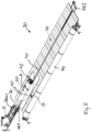
- a device 30 for producing a load-bearing surface, in particular a membrane surface 50, from sheet metal strips 10 welded together is shown schematically using the method described above. The situation is presented in which the first two metal strips 10 of the membrane surface 50 are welded together.
- a bearing roller device 32 is arranged on the left end region, on which a sheet metal strip 10 is mounted as a removable coil.
- the metal strip 10 is drawn off onto a support device 34 up to a predetermined length in the longitudinal direction L by means of a first withdrawal device 36.
- first shaping device 38 is present, which impresses a groove in the edge region on both sides of the removed sheet metal strip 10.
- the second forming device 40 shown schematically, which produces the upstand in the edge region on both sides of the removed sheet metal strip, the bending edge of the upstand 16 lying in the groove 12.
- the welding device 42 After the first sheet metal strip 10 has been pulled off, it is pulled off by the width dimension b of the sheet metal strip 10 by a further pull-off device (not shown) after reaching its longitudinal position in the transverse direction Q. After a second sheet metal strip 10 has been drawn in, the welding device 42 is used, which melts the upstands 16 of adjacent sheet metal strips 10 and thus welds them together. The welding device 42 advances progressively in the longitudinal direction L, and after a certain weld seam length has been reached, the circumferential contour of the membrane surface 50 - in the exemplary embodiment shown, a circular circumferential contour - is cut off accordingly from the sheet metal strips 10, as in Fig. 4 shown. During the welding process, the two sheet metal strips 10 to be welded together are used with the help of the left and right end regions Support device 34 existing pretensioning devices 46.1, 46.2 kept under pretension.
- the two sheet metal strips 10 After the two sheet metal strips 10 have been welded together, they are pulled off in the transverse direction Q with the further take-off device and fed to a further bearing roller device 44 and wound onto it.
- the further bearing roller device 44 serves as a transport device for the finished membrane surface 50 for transport to the construction site.
- additional metal strips 10 are now peeled off, provided with grooves and upstands and welded together in their longitudinal edge area until the finished membrane surface 50 is produced.
- the membrane surface 50 In the finished state, the membrane surface 50 is then wound onto the further bearing roller device 44 and can be transported to the construction site.
- FIG. 6 to 9 An exemplary embodiment of a welding device 42 is shown schematically during the welding process.
- the welding device 42 is arranged on a welding carriage that can be moved in the longitudinal direction L and has an autonomous drive.
- the welding device 42 has in its front end region two opposite pressure rollers 24, which, when used, have a pressing effect on the adjacent upstands 16 of adjacent sheet metal strips 10 from the outside and are driven rotatably about an axis of rotation and thus the travel movement of the carriage of the welding device 42 in the longitudinal direction L make possible.
- the in Fig. 7 The welding head 18 of the welding device 42 that can be seen is present in the rear end region of the welding device 42.
- the welding device 42 is designed as an inert gas welding device, that is to say the welding head 18 is supplied with gases from storage containers 64 in order to cause the upstands 16 of the sheet metal strips 10 to melt through their combustion in order to thereby produce the desired weld seam.
- a gap generating device 48 is arranged, which is connected to the welding device 42 via a distance profile 49, which ensures that the adjacent edge regions of the sheet metal strips 10 are kept at a defined gap dimension distance, so that there are no overthrows of the Membrane-like sheet metal strips 10 can come during the welding process, which is beneficial for the trouble-free process.
- the upstands 16 of adjacent sheet metal strips 10 are brought together in contact by the pressure rollers 24 of the welding device 42 and then melted to form the weld seam.
- the welding head 18 of the welding device 42 is structurally designed or mounted in such a way that it carries out an oscillating or pendulum-like movement transversely to the longitudinal direction L during the advance of the welding device 42 in the longitudinal direction L, whereby the quality of the weld seam produced is significantly improved.
- an eccentric drive for the welding head 18 can be used, for example.
- the Figures 10 to 13 show schematically the front area of the device 30.
- the respective sheet metal strip 10 is rotatably and detachably wound onto a bearing roller device 32, which is usually called a coil.
- the withdrawal device 36 which is connected to the front end region of a sheet metal strip 10 to be pulled off, pulls this sheet metal strip in the longitudinal direction L onto the support device 34 up to a predetermined length.
- the sheet metal strip 10 is fed to a first forming device 40, which in the exemplary embodiment shown is designed as a roller unit and the corresponding groove 12 is embossed in the respective side edge area on the top side of the metal strip 10.
- the first forming device 38 is immediately followed by the second forming device 40, which in the exemplary embodiment shown consists of several rollers arranged one behind the other in the longitudinal direction L, and which creates the upstand 16 in the edge region of the sheet metal strip 10.
- This pre-edged sheet metal strip 10 is then, after it has reached the predetermined extension length on the support device 34, butt-welded to one another by means of the welding device 42 described above, the upturns 16 being melted during the welding process, thereby producing a permanently reliable, tight weld seam with a high load-bearing capacity .
- the strips are separated from the coil and then welded. After the welding has taken place, the sheet metal strips 10 welded together are pulled off in the transverse direction Q by the respective sheet width b and fed to the further bearing roller device 44. Then another sheet metal strip 10 is pulled off and made available for the next welding process.
- any size surface can be produced from sheet metal strips that have any circumferential contour, since the circumferential contour is created during the welding process by appropriate contour treatment of the edge regions of the joined sheet metal strips.
- the volume of the material to be melted to form a weld seam is reduced, so that a lower energy input is possible, and the occurrence of warping or wave formation in the supporting surface is thereby effectively counteracted.
- welds with a smaller thickness can be achieved, so that an overall smoother surface can be achieved.
- the creation of undesirable internal stresses within the surface is thereby counteracted.
- the use of the inventive method is not necessary and the production of a groove can be dispensed with and the remaining process steps can be applied accordingly.
Landscapes
- Engineering & Computer Science (AREA)
- Mechanical Engineering (AREA)
- Physics & Mathematics (AREA)
- Optics & Photonics (AREA)
- Butt Welding And Welding Of Specific Article (AREA)
Claims (22)
- Procédé de soudage de zones de bords longitudinaux de bandes de tôle (10) en contact bout à bout, comprenant les étapes de procédé suivantes :- réalisation d'un bord plié (16) le long du bord longitudinal respectif (14) de la bande de tôle (10),- jonction des bords (16) de bandes de tôle (10) voisines,- fusion des bords pliés (16) assemblés de bandes de tôle (10) voisines au moyen d'une soudure progressant dans la direction longitudinale (L) des bandes de tôle (10) en utilisant une tête de soudage (18) sans utilisation de matériau de soudage supplémentaire, caractérisé en ce qu'un bourrelet ou une rainure est réalisé(e) avec une distance (a) prédéfinie parallèlement au bord longitudinal (14) de chaque bande de tôle et en ce que la longueur de section transversale du bord plié (16) correspond à la distance (a) du bourrelet/de la rainure (12).
- Procédé selon la revendication 1,- caractérisé en ce que- le bourrelet/la rainure (12) est réalisé(e) par déformation à froid.
- Procédé selon la revendication 2,- caractérisé en ce que- le bourrelet/la rainure (12) est réalisé(e) par un procédé de poinçonnage ou de laminage.
- Procédé selon la revendication 1,- caractérisé en ce que- le bourrelet/la rainure (12) est réalisé (e) par enlèvement de matière.
- Procédé selon l'une des revendications 1 à 4,- caractérisé en ce que- le bourrelet/la rainure (12) est appliqué(e) sur la face supérieure et/ou inférieure de la bande de tôle (10) concernée.
- Procédé selon l'une des revendications 1 à 5,- caractérisé en ce que- le bourrelet/la rainure (12) est appliqué(e) à une distance (a) du bord longitudinal (14) de la bande de tôle (10) qui correspond à 3 à 10 fois, en particulier à 2 à 5 fois, l'épaisseur de la bande de tôle (10).
- Procédé selon l'une des revendications 1 à 6,- caractérisé en ce que- on utilise une bande de tôle (10) dont la résistance/l'épaisseur est comprise entre 0,5 et 3 mm (millimètres), notamment entre 0,5 et 2 mm (millimètres).
- Procédé selon la revendication 1,- caractérisé en ce que- le bord (16) est réalisé perpendiculairement au plan (E) de la bande de tôle (10).
- Procédé selon l'une des revendications 1 à 8,- caractérisé en ce que- la tête de soudage (18) effectue un mouvement oscillant dans la direction longitudinale (L) lors du soudage ou pendulaire transversalement à la direction longitudinale (L) pendant le procédé de soudage.
- Procédé selon l'une des revendications 1 à 9,- caractérisé en ce que- une torche de soudage, une électrode de soudage ou une soudeuse au laser est utilisée pour fusionner les bords (16) assemblés.
- Procédé selon l'une des revendications 1 à 10,- caractérisé en ce que- les zones de bord longitudinal voisines à souder des bandes de tôle (10) sont maintenues espacées dans la direction longitudinale (L) avant la position de soudage avec une distance de fente prédéfinie et les bords pliés (16) sont pressés l'un contre l'autre immédiatement avant la position de soudage.
- Procédé selon l'une des revendications 1 à 11,- caractérisé en ce que- une couche de matériau thermo-conducteur (20) est disposée directement en dessous et en contact avec les zones de bord longitudinal à souder des bandes de tôle (10) .
- Procédé selon l'une des revendications 1 à 12,- caractérisé en ce que- des bandes de tôle (10) en acier inoxydable sont utilisées.
- Procédé selon l'une des revendications 1 à 13,- caractérisé en ce que- on utilise des bandes de tôle (10) qui ont la forme d'une membrane.
- Dispositif pour la fabrication d'une grande surface à partir de bandes de tôle soudées entre elles en utilisant le procédé selon l'une des revendications 1 à 14, comprenant :- un dispositif de formage (40) pour réaliser un bord plié (16) dans la zone de bordure des deux côtés d'une bande de tôle (10) étirée,- un dispositif de soudage (42) avec une tête de soudage (18), qui est apte à être déplacé dans la direction longitudinale (L) et qui effectue la fusion de bords pliés (16) assemblés de bandes de tôle (10) voisines, caractérisé par- un dispositif de rouleaux de support (32) sur lequel une bande de tôle (10) est montée de manière à pouvoir être tirée sous forme de bobine,- un dispositif de support (34) pour la bande de tôle (10) extraite du dispositif à rouleaux de support,- un premier dispositif de tirage (36) pour le tirage de la bande de tôle (10) du dispositif à rouleaux de stockage (32) à une dimension longitudinale prédéfinie,- un autre dispositif de formage (38) pour la fabrication du bourrelet/de la rainure (12) avec une distance prédéfinie (a) parallèlement au bord longitudinal (14) dans la zone de bord des deux côtés d'une bande de tôle (10) retirée,- caractérisé en ce que la longueur de la section transversale du bord plié (16) fabriqué par le dispositif de formage (40) pour fabriquer le bord plié (16) correspond à la distance du bourrelet/de la rainure (16), et caractérisé en outre par- un autre dispositif de tirage, qui tire des bandes de tôle (10) reliées, après la réalisation de l'assemblage soudé, dans la direction transversale, respectivement de la dimension de largeur (b) d'une bande de tôle (10).
- Dispositif selon la revendication 15,- caractérisé en ce que- il existe un autre dispositif à rouleaux de support (44) sur lequel sont enroulées les bandes de tôle soudées (10) extraites par ledit autre dispositif de tirage.
- Dispositif selon la revendication 15 ou 16,- caractérisé en ce que- un dispositif de précontrainte (46.1, 46.2) est présent, qui maintient sous précontrainte les deux bandes de tôle (10) respectives à souder l'une à l'autre pendant l'opération de soudage.
- Dispositif selon l'une des revendications 15 à 17,- caractérisé en ce que- un dispositif (48) de génération de fente est présent, relié au dispositif de soudage (42), qui génère une distance de fente définie entre les deux bandes de tôle (10) à souder, à une certaine distance dans le sens longitudinal (L) devant le dispositif de soudage (42).
- Dispositif selon l'une des revendications 15 à 18,- caractérisé en ce que- le dispositif de support (34) contient un rail (20) conducteur de chaleur, en particulier en cuivre, qui est disposé directement en dessous des zones de bord longitudinal des bandes de tôle (10) à souder et sur lequel des zones de bord longitudinal sont appuyées pendant l'opération de soudage.
- Dispositif selon l'une quelconque des revendications 15 à 19,- caractérisé en ce que- la tête de soudage (18) du dispositif de soudage (42) déplaçable dans la direction longitudinale (L) est conçue/positionnée de manière à pouvoir effectuer un mouvement oscillant ou pendulaire transversalement à la direction longitudinale (L) pendant l'opération de soudage.
- Dispositif selon l'une des revendications 15 à 20,- caractérisé en ce que- le dispositif de soudage (42) comporte deux rouleaux de pression (24) opposés, qui pressent l'un contre l'autre les bords pliés (16) de deux bandes de tôle (10) espacées avant la position de soudage.
- Dispositif selon la revendication 20,- caractérisé en ce que- le dispositif de soudage (42) présente un entraînement excentrique pour l'exécution du mouvement oscillant ou pendulaire de la tête de soudage (18) transversalement à la direction longitudinale (L) pendant l'opération de soudage
Applications Claiming Priority (2)
| Application Number | Priority Date | Filing Date | Title |
|---|---|---|---|
| DE102018006603.8A DE102018006603A1 (de) | 2018-08-22 | 2018-08-22 | Verfahren zum Verschweißen von Blechstreifen und Vorrichtung zur Herstellung einer großen Fläche unter Einsatz eines derartigen Verfahrens |
| PCT/DE2019/000215 WO2020038504A2 (fr) | 2018-08-22 | 2019-08-09 | Procédé de soudage de bandes de tôles et dispositif pour produire une grande surface en utilisant un tel procédé |
Publications (2)
| Publication Number | Publication Date |
|---|---|
| EP3840913A2 EP3840913A2 (fr) | 2021-06-30 |
| EP3840913B1 true EP3840913B1 (fr) | 2023-10-18 |
Family
ID=65084532
Family Applications (1)
| Application Number | Title | Priority Date | Filing Date |
|---|---|---|---|
| EP19762296.2A Active EP3840913B1 (fr) | 2018-08-22 | 2019-08-09 | Procédé de soudage de bandes de tôles et dispositif pour produire une grande surface en utilisant un tel procédé |
Country Status (4)
| Country | Link |
|---|---|
| EP (1) | EP3840913B1 (fr) |
| CN (1) | CN112584967B (fr) |
| DE (2) | DE102018006603A1 (fr) |
| WO (1) | WO2020038504A2 (fr) |
Families Citing this family (4)
| Publication number | Priority date | Publication date | Assignee | Title |
|---|---|---|---|---|
| DE102020115374B4 (de) | 2020-06-10 | 2022-06-15 | Xl Beteiligungen Gmbh & Co. Kg | Großraumbehälter und Verfahren zum Herstellen eines Großraumbehälters |
| CN114309941B (zh) * | 2022-01-13 | 2024-08-23 | 上海蓝魂环保科技有限公司 | 一种金属薄板结构卷边焊接施工组合工具及方法 |
| DE102022101389A1 (de) * | 2022-01-21 | 2023-07-27 | Lipp & Mayer Technologie GmbH | Metallbandeinrichtung und Wandung eines Behälters, insbesondere eines Silos, mit einer derartigen wendelförmig verlaufenden Metallbandeinrichtung |
| CN114713949B (zh) * | 2022-03-23 | 2024-05-28 | 西安菲尔特金属过滤材料股份有限公司 | 一种用于金属网带自动焊接背面气体保护装置 |
Citations (4)
| Publication number | Priority date | Publication date | Assignee | Title |
|---|---|---|---|---|
| US2515179A (en) * | 1946-10-29 | 1950-07-18 | American Can Co | Method of producing container bodies |
| US2629806A (en) * | 1944-10-23 | 1953-02-24 | Chicago Metal Hose Corp | Welding method and article produced thereby |
| JPS58110174A (ja) * | 1981-12-23 | 1983-06-30 | Fuji Seikou Kk | 溶接方法 |
| EP0855241A1 (fr) * | 1997-01-27 | 1998-07-29 | Manfred Strub | Méthode de fabrication d'une liaison étanche entre deux tÔles |
Family Cites Families (11)
| Publication number | Priority date | Publication date | Assignee | Title |
|---|---|---|---|---|
| DE1168218B (de) * | 1961-09-25 | 1964-04-16 | Csf | Ausbildung der zum Schmelzschweissen ohne Zusatzwerkstoff abgebogenen Raender von Duennblechen |
| AT370357B (de) * | 1981-09-08 | 1983-03-25 | Steyr Daimler Puch Ag | Schweissverbindung fuer karosseriebleche |
| DE3739359C1 (en) | 1987-11-20 | 1989-01-19 | Xaver Lipp | Welding apparatus for producing an assembled sheet-metal panel |
| DE3709843A1 (de) | 1987-03-25 | 1988-10-13 | Xaver Lipp | Abdeckung fuer behaelter mit grossem durchmesser |
| DE4039113A1 (de) * | 1990-12-07 | 1992-06-11 | Xaver Lipp | Verfahren zur herstellung einer zusammengesetzten blechtafel und schweisswagen zur durchfuehrung des verfahrens |
| DE19529542C2 (de) | 1995-08-11 | 1998-09-17 | Xaver Lipp | Verfahren und Vorrichtung zum Verschweißen stumpf aneinanderstoßender Bleche, insbesondere in Form von Streifen |
| DE19750586B4 (de) * | 1997-11-17 | 2007-05-16 | Volkswagen Ag | Laser-Lötverfahren |
| DE10232524A1 (de) * | 2002-07-18 | 2004-01-29 | Bayerische Motoren Werke Ag | Verfahren zum Verschweißen zweier Blechteile und Werkzeugmaschine zum Verschweißen zweier Blechteile |
| JP2005297026A (ja) * | 2004-04-13 | 2005-10-27 | Nippon Steel Corp | 金属板材のレーザー溶接方法及びレーザー溶接用金属板材 |
| CN202539869U (zh) * | 2012-03-23 | 2012-11-21 | 河北融阳光伏科技有限公司 | 电池片汇流焊接模板 |
| KR20170031839A (ko) * | 2015-09-11 | 2017-03-22 | 현대자동차주식회사 | 차량용 범퍼 백빔의 제조방법 |
-
2018
- 2018-08-22 DE DE102018006603.8A patent/DE102018006603A1/de not_active Withdrawn
-
2019
- 2019-08-09 DE DE112019004163.0T patent/DE112019004163A5/de not_active Withdrawn
- 2019-08-09 EP EP19762296.2A patent/EP3840913B1/fr active Active
- 2019-08-09 CN CN201980054778.1A patent/CN112584967B/zh active Active
- 2019-08-09 WO PCT/DE2019/000215 patent/WO2020038504A2/fr not_active Ceased
Patent Citations (4)
| Publication number | Priority date | Publication date | Assignee | Title |
|---|---|---|---|---|
| US2629806A (en) * | 1944-10-23 | 1953-02-24 | Chicago Metal Hose Corp | Welding method and article produced thereby |
| US2515179A (en) * | 1946-10-29 | 1950-07-18 | American Can Co | Method of producing container bodies |
| JPS58110174A (ja) * | 1981-12-23 | 1983-06-30 | Fuji Seikou Kk | 溶接方法 |
| EP0855241A1 (fr) * | 1997-01-27 | 1998-07-29 | Manfred Strub | Méthode de fabrication d'une liaison étanche entre deux tÔles |
Also Published As
| Publication number | Publication date |
|---|---|
| WO2020038504A2 (fr) | 2020-02-27 |
| DE102018006603A1 (de) | 2019-02-14 |
| DE112019004163A5 (de) | 2021-06-17 |
| WO2020038504A3 (fr) | 2020-04-16 |
| CN112584967B (zh) | 2022-10-14 |
| EP3840913A2 (fr) | 2021-06-30 |
| BR112021002645A2 (pt) | 2021-05-25 |
| CN112584967A (zh) | 2021-03-30 |
Similar Documents
| Publication | Publication Date | Title |
|---|---|---|
| EP3840913A2 (fr) | Procédé de soudage de bandes de tôles et dispositif pour produire une grande surface en utilisant un tel procédé | |
| EP2720849B1 (fr) | Procede de fabrication de corps tubulaires pour tubes d'emballage et tube d'emballage | |
| DE3802000A1 (de) | Aus metallblech gefertigter behaelter | |
| DE102013219315A1 (de) | Verfahren zur Herstellung einer Fahrzeugkarosserie | |
| DE2812415A1 (de) | Verfahren zur herstellung verschweisster blechprofile sowie vorrichtung zur durchfuehrung dieses verfahrens | |
| DE2508592A1 (de) | Konsole fuer stahlgeruesthochbauten | |
| DE3233048C2 (fr) | ||
| DE69002760T2 (de) | Verfahren zur herstellung quadratischer röhren aus beschichteten stahlbändern. | |
| EP2720850B1 (fr) | Procédé de fabrication de corps tubulaires pour tubes d'emballage et tube d'emballage comportant un corps tubulaire | |
| EP3969690B1 (fr) | Contenant produit à partir d'une bande de tôle courbée de manière hélicoïdale et procédé pour produire un tel contenant | |
| DE10218986A1 (de) | Verfahren zur Herstellung eines Kraftstoffbehälters | |
| DE10204638B4 (de) | Verfahren zum Herstellen eines Metallblechtürblatts | |
| DE102013219317B4 (de) | Verfahren zur Herstellung einer Fahrzeugkarosserie und Fahrzeugkarosserie | |
| EP1705446A1 (fr) | Tube pour un échangeur de chaleur | |
| EP3048231B1 (fr) | Profilé métallique, profilé composite avec un tel profilé métallique ainsi que procédé de fabrication du profilé métallique | |
| DE19640754A1 (de) | Strahlgeschweißter Verbund eines Karosseriebleches mit einem Rollprofil und Verfahren zu dessen Herstellung | |
| DE10149183A1 (de) | Verfahren zur Herstellung von Kanten- oder stirnseitig miteinander verbundenen Blechen und stirnseitig miteinander verbundene Bleche | |
| WO1999062669A1 (fr) | Procede pour former un assemblage de toles, et dispositif et jeu de sections de tole approprie | |
| EP4400287B1 (fr) | Dispositif, procédé et appareil de liaison mobile pour la liaison thermique de deux bandes de matériau adjacentes à travers d'une pièce de liaison | |
| DE10009126A1 (de) | Anordnung eines tragenden Bauteils einer Fahrzeugkarosserie | |
| EP3048232B1 (fr) | Profilé métallique, profilé composite avec un tel profilé métallique ainsi que procédé de fabrication du profilé métallique | |
| DE102004008108A1 (de) | Überlappstoß zum Schweißen von beschichteten Werkstücken | |
| DE2847023C2 (de) | Spiegelpreßschweißvorrichtung zum Verbinden von Kunststoffprofilen | |
| EP0490091A2 (fr) | Méthode de fabrication d'une feuille de tôle composite et chariot de sondage pour mettre en oeuvre ladite méthode | |
| DE102023122786A1 (de) | Fensterprofil sowie Verfahren zur Herstellung eines Fensterprofils |
Legal Events
| Date | Code | Title | Description |
|---|---|---|---|
| STAA | Information on the status of an ep patent application or granted ep patent |
Free format text: STATUS: UNKNOWN |
|
| STAA | Information on the status of an ep patent application or granted ep patent |
Free format text: STATUS: THE INTERNATIONAL PUBLICATION HAS BEEN MADE |
|
| PUAI | Public reference made under article 153(3) epc to a published international application that has entered the european phase |
Free format text: ORIGINAL CODE: 0009012 |
|
| STAA | Information on the status of an ep patent application or granted ep patent |
Free format text: STATUS: REQUEST FOR EXAMINATION WAS MADE |
|
| 17P | Request for examination filed |
Effective date: 20210318 |
|
| AK | Designated contracting states |
Kind code of ref document: A2 Designated state(s): AL AT BE BG CH CY CZ DE DK EE ES FI FR GB GR HR HU IE IS IT LI LT LU LV MC MK MT NL NO PL PT RO RS SE SI SK SM TR |
|
| DAV | Request for validation of the european patent (deleted) | ||
| DAX | Request for extension of the european patent (deleted) | ||
| GRAP | Despatch of communication of intention to grant a patent |
Free format text: ORIGINAL CODE: EPIDOSNIGR1 |
|
| STAA | Information on the status of an ep patent application or granted ep patent |
Free format text: STATUS: GRANT OF PATENT IS INTENDED |
|
| INTG | Intention to grant announced |
Effective date: 20230510 |
|
| GRAS | Grant fee paid |
Free format text: ORIGINAL CODE: EPIDOSNIGR3 |
|
| GRAA | (expected) grant |
Free format text: ORIGINAL CODE: 0009210 |
|
| STAA | Information on the status of an ep patent application or granted ep patent |
Free format text: STATUS: THE PATENT HAS BEEN GRANTED |
|
| AK | Designated contracting states |
Kind code of ref document: B1 Designated state(s): AL AT BE BG CH CY CZ DE DK EE ES FI FR GB GR HR HU IE IS IT LI LT LU LV MC MK MT NL NO PL PT RO RS SE SI SK SM TR |
|
| REG | Reference to a national code |
Ref country code: GB Ref legal event code: FG4D Free format text: NOT ENGLISH |
|
| REG | Reference to a national code |
Ref country code: CH Ref legal event code: EP |
|
| REG | Reference to a national code |
Ref country code: IE Ref legal event code: FG4D Free format text: LANGUAGE OF EP DOCUMENT: GERMAN |
|
| REG | Reference to a national code |
Ref country code: DE Ref legal event code: R096 Ref document number: 502019009716 Country of ref document: DE |
|
| REG | Reference to a national code |
Ref country code: LT Ref legal event code: MG9D |
|
| REG | Reference to a national code |
Ref country code: NL Ref legal event code: MP Effective date: 20231018 |
|
| PG25 | Lapsed in a contracting state [announced via postgrant information from national office to epo] |
Ref country code: NL Free format text: LAPSE BECAUSE OF FAILURE TO SUBMIT A TRANSLATION OF THE DESCRIPTION OR TO PAY THE FEE WITHIN THE PRESCRIBED TIME-LIMIT Effective date: 20231018 |
|
| PG25 | Lapsed in a contracting state [announced via postgrant information from national office to epo] |
Ref country code: GR Free format text: LAPSE BECAUSE OF FAILURE TO SUBMIT A TRANSLATION OF THE DESCRIPTION OR TO PAY THE FEE WITHIN THE PRESCRIBED TIME-LIMIT Effective date: 20240119 |
|
| PG25 | Lapsed in a contracting state [announced via postgrant information from national office to epo] |
Ref country code: IS Free format text: LAPSE BECAUSE OF FAILURE TO SUBMIT A TRANSLATION OF THE DESCRIPTION OR TO PAY THE FEE WITHIN THE PRESCRIBED TIME-LIMIT Effective date: 20240218 |
|
| PG25 | Lapsed in a contracting state [announced via postgrant information from national office to epo] |
Ref country code: LT Free format text: LAPSE BECAUSE OF FAILURE TO SUBMIT A TRANSLATION OF THE DESCRIPTION OR TO PAY THE FEE WITHIN THE PRESCRIBED TIME-LIMIT Effective date: 20231018 |
|
| PG25 | Lapsed in a contracting state [announced via postgrant information from national office to epo] |
Ref country code: ES Free format text: LAPSE BECAUSE OF FAILURE TO SUBMIT A TRANSLATION OF THE DESCRIPTION OR TO PAY THE FEE WITHIN THE PRESCRIBED TIME-LIMIT Effective date: 20231018 |
|
| PG25 | Lapsed in a contracting state [announced via postgrant information from national office to epo] |
Ref country code: LT Free format text: LAPSE BECAUSE OF FAILURE TO SUBMIT A TRANSLATION OF THE DESCRIPTION OR TO PAY THE FEE WITHIN THE PRESCRIBED TIME-LIMIT Effective date: 20231018 Ref country code: IS Free format text: LAPSE BECAUSE OF FAILURE TO SUBMIT A TRANSLATION OF THE DESCRIPTION OR TO PAY THE FEE WITHIN THE PRESCRIBED TIME-LIMIT Effective date: 20240218 Ref country code: GR Free format text: LAPSE BECAUSE OF FAILURE TO SUBMIT A TRANSLATION OF THE DESCRIPTION OR TO PAY THE FEE WITHIN THE PRESCRIBED TIME-LIMIT Effective date: 20240119 Ref country code: ES Free format text: LAPSE BECAUSE OF FAILURE TO SUBMIT A TRANSLATION OF THE DESCRIPTION OR TO PAY THE FEE WITHIN THE PRESCRIBED TIME-LIMIT Effective date: 20231018 Ref country code: BG Free format text: LAPSE BECAUSE OF FAILURE TO SUBMIT A TRANSLATION OF THE DESCRIPTION OR TO PAY THE FEE WITHIN THE PRESCRIBED TIME-LIMIT Effective date: 20240118 Ref country code: PT Free format text: LAPSE BECAUSE OF FAILURE TO SUBMIT A TRANSLATION OF THE DESCRIPTION OR TO PAY THE FEE WITHIN THE PRESCRIBED TIME-LIMIT Effective date: 20240219 |
|
| PG25 | Lapsed in a contracting state [announced via postgrant information from national office to epo] |
Ref country code: SE Free format text: LAPSE BECAUSE OF FAILURE TO SUBMIT A TRANSLATION OF THE DESCRIPTION OR TO PAY THE FEE WITHIN THE PRESCRIBED TIME-LIMIT Effective date: 20231018 Ref country code: RS Free format text: LAPSE BECAUSE OF FAILURE TO SUBMIT A TRANSLATION OF THE DESCRIPTION OR TO PAY THE FEE WITHIN THE PRESCRIBED TIME-LIMIT Effective date: 20231018 Ref country code: PL Free format text: LAPSE BECAUSE OF FAILURE TO SUBMIT A TRANSLATION OF THE DESCRIPTION OR TO PAY THE FEE WITHIN THE PRESCRIBED TIME-LIMIT Effective date: 20231018 Ref country code: NO Free format text: LAPSE BECAUSE OF FAILURE TO SUBMIT A TRANSLATION OF THE DESCRIPTION OR TO PAY THE FEE WITHIN THE PRESCRIBED TIME-LIMIT Effective date: 20240118 Ref country code: LV Free format text: LAPSE BECAUSE OF FAILURE TO SUBMIT A TRANSLATION OF THE DESCRIPTION OR TO PAY THE FEE WITHIN THE PRESCRIBED TIME-LIMIT Effective date: 20231018 Ref country code: HR Free format text: LAPSE BECAUSE OF FAILURE TO SUBMIT A TRANSLATION OF THE DESCRIPTION OR TO PAY THE FEE WITHIN THE PRESCRIBED TIME-LIMIT Effective date: 20231018 |
|
| PG25 | Lapsed in a contracting state [announced via postgrant information from national office to epo] |
Ref country code: DK Free format text: LAPSE BECAUSE OF FAILURE TO SUBMIT A TRANSLATION OF THE DESCRIPTION OR TO PAY THE FEE WITHIN THE PRESCRIBED TIME-LIMIT Effective date: 20231018 |
|
| REG | Reference to a national code |
Ref country code: DE Ref legal event code: R097 Ref document number: 502019009716 Country of ref document: DE |
|
| PG25 | Lapsed in a contracting state [announced via postgrant information from national office to epo] |
Ref country code: CZ Free format text: LAPSE BECAUSE OF FAILURE TO SUBMIT A TRANSLATION OF THE DESCRIPTION OR TO PAY THE FEE WITHIN THE PRESCRIBED TIME-LIMIT Effective date: 20231018 |
|
| PG25 | Lapsed in a contracting state [announced via postgrant information from national office to epo] |
Ref country code: SK Free format text: LAPSE BECAUSE OF FAILURE TO SUBMIT A TRANSLATION OF THE DESCRIPTION OR TO PAY THE FEE WITHIN THE PRESCRIBED TIME-LIMIT Effective date: 20231018 |
|
| PG25 | Lapsed in a contracting state [announced via postgrant information from national office to epo] |
Ref country code: SM Free format text: LAPSE BECAUSE OF FAILURE TO SUBMIT A TRANSLATION OF THE DESCRIPTION OR TO PAY THE FEE WITHIN THE PRESCRIBED TIME-LIMIT Effective date: 20231018 Ref country code: SK Free format text: LAPSE BECAUSE OF FAILURE TO SUBMIT A TRANSLATION OF THE DESCRIPTION OR TO PAY THE FEE WITHIN THE PRESCRIBED TIME-LIMIT Effective date: 20231018 Ref country code: RO Free format text: LAPSE BECAUSE OF FAILURE TO SUBMIT A TRANSLATION OF THE DESCRIPTION OR TO PAY THE FEE WITHIN THE PRESCRIBED TIME-LIMIT Effective date: 20231018 Ref country code: EE Free format text: LAPSE BECAUSE OF FAILURE TO SUBMIT A TRANSLATION OF THE DESCRIPTION OR TO PAY THE FEE WITHIN THE PRESCRIBED TIME-LIMIT Effective date: 20231018 Ref country code: DK Free format text: LAPSE BECAUSE OF FAILURE TO SUBMIT A TRANSLATION OF THE DESCRIPTION OR TO PAY THE FEE WITHIN THE PRESCRIBED TIME-LIMIT Effective date: 20231018 Ref country code: CZ Free format text: LAPSE BECAUSE OF FAILURE TO SUBMIT A TRANSLATION OF THE DESCRIPTION OR TO PAY THE FEE WITHIN THE PRESCRIBED TIME-LIMIT Effective date: 20231018 |
|
| PLBE | No opposition filed within time limit |
Free format text: ORIGINAL CODE: 0009261 |
|
| STAA | Information on the status of an ep patent application or granted ep patent |
Free format text: STATUS: NO OPPOSITION FILED WITHIN TIME LIMIT |
|
| 26N | No opposition filed |
Effective date: 20240719 |
|
| PG25 | Lapsed in a contracting state [announced via postgrant information from national office to epo] |
Ref country code: SI Free format text: LAPSE BECAUSE OF FAILURE TO SUBMIT A TRANSLATION OF THE DESCRIPTION OR TO PAY THE FEE WITHIN THE PRESCRIBED TIME-LIMIT Effective date: 20231018 |
|
| PG25 | Lapsed in a contracting state [announced via postgrant information from national office to epo] |
Ref country code: SI Free format text: LAPSE BECAUSE OF FAILURE TO SUBMIT A TRANSLATION OF THE DESCRIPTION OR TO PAY THE FEE WITHIN THE PRESCRIBED TIME-LIMIT Effective date: 20231018 |
|
| REG | Reference to a national code |
Ref country code: CH Ref legal event code: PL |
|
| PG25 | Lapsed in a contracting state [announced via postgrant information from national office to epo] |
Ref country code: LU Free format text: LAPSE BECAUSE OF NON-PAYMENT OF DUE FEES Effective date: 20240809 |
|
| GBPC | Gb: european patent ceased through non-payment of renewal fee |
Effective date: 20240809 |
|
| PG25 | Lapsed in a contracting state [announced via postgrant information from national office to epo] |
Ref country code: MC Free format text: LAPSE BECAUSE OF FAILURE TO SUBMIT A TRANSLATION OF THE DESCRIPTION OR TO PAY THE FEE WITHIN THE PRESCRIBED TIME-LIMIT Effective date: 20231018 Ref country code: CH Free format text: LAPSE BECAUSE OF NON-PAYMENT OF DUE FEES Effective date: 20240831 |
|
| REG | Reference to a national code |
Ref country code: BE Ref legal event code: MM Effective date: 20240831 |
|
| PG25 | Lapsed in a contracting state [announced via postgrant information from national office to epo] |
Ref country code: GB Free format text: LAPSE BECAUSE OF NON-PAYMENT OF DUE FEES Effective date: 20240809 |
|
| PG25 | Lapsed in a contracting state [announced via postgrant information from national office to epo] |
Ref country code: BE Free format text: LAPSE BECAUSE OF NON-PAYMENT OF DUE FEES Effective date: 20240831 |
|
| PG25 | Lapsed in a contracting state [announced via postgrant information from national office to epo] |
Ref country code: FR Free format text: LAPSE BECAUSE OF NON-PAYMENT OF DUE FEES Effective date: 20240831 |
|
| PG25 | Lapsed in a contracting state [announced via postgrant information from national office to epo] |
Ref country code: IE Free format text: LAPSE BECAUSE OF NON-PAYMENT OF DUE FEES Effective date: 20240809 |
|
| PG25 | Lapsed in a contracting state [announced via postgrant information from national office to epo] |
Ref country code: FI Free format text: LAPSE BECAUSE OF FAILURE TO SUBMIT A TRANSLATION OF THE DESCRIPTION OR TO PAY THE FEE WITHIN THE PRESCRIBED TIME-LIMIT Effective date: 20231019 |
|
| PGFP | Annual fee paid to national office [announced via postgrant information from national office to epo] |
Ref country code: DE Payment date: 20250821 Year of fee payment: 7 |
|
| PGFP | Annual fee paid to national office [announced via postgrant information from national office to epo] |
Ref country code: IT Payment date: 20250829 Year of fee payment: 7 |
|
| REG | Reference to a national code |
Ref country code: AT Ref legal event code: MM01 Ref document number: 1621989 Country of ref document: AT Kind code of ref document: T Effective date: 20240809 |
|
| PG25 | Lapsed in a contracting state [announced via postgrant information from national office to epo] |
Ref country code: AT Free format text: LAPSE BECAUSE OF NON-PAYMENT OF DUE FEES Effective date: 20240809 |
|
| PG25 | Lapsed in a contracting state [announced via postgrant information from national office to epo] |
Ref country code: CY Free format text: LAPSE BECAUSE OF FAILURE TO SUBMIT A TRANSLATION OF THE DESCRIPTION OR TO PAY THE FEE WITHIN THE PRESCRIBED TIME-LIMIT; INVALID AB INITIO Effective date: 20190809 |
|
| PG25 | Lapsed in a contracting state [announced via postgrant information from national office to epo] |
Ref country code: HU Free format text: LAPSE BECAUSE OF FAILURE TO SUBMIT A TRANSLATION OF THE DESCRIPTION OR TO PAY THE FEE WITHIN THE PRESCRIBED TIME-LIMIT; INVALID AB INITIO Effective date: 20190809 |