EP3048232B1 - Profilé métallique, profilé composite avec un tel profilé métallique ainsi que procédé de fabrication du profilé métallique - Google Patents
Profilé métallique, profilé composite avec un tel profilé métallique ainsi que procédé de fabrication du profilé métallique Download PDFInfo
- Publication number
- EP3048232B1 EP3048232B1 EP15152188.7A EP15152188A EP3048232B1 EP 3048232 B1 EP3048232 B1 EP 3048232B1 EP 15152188 A EP15152188 A EP 15152188A EP 3048232 B1 EP3048232 B1 EP 3048232B1
- Authority
- EP
- European Patent Office
- Prior art keywords
- profile
- metal
- groove
- sections
- sheet
- Prior art date
- Legal status (The legal status is an assumption and is not a legal conclusion. Google has not performed a legal analysis and makes no representation as to the accuracy of the status listed.)
- Active
Links
Images
Classifications
-
- E—FIXED CONSTRUCTIONS
- E06—DOORS, WINDOWS, SHUTTERS, OR ROLLER BLINDS IN GENERAL; LADDERS
- E06B—FIXED OR MOVABLE CLOSURES FOR OPENINGS IN BUILDINGS, VEHICLES, FENCES OR LIKE ENCLOSURES IN GENERAL, e.g. DOORS, WINDOWS, BLINDS, GATES
- E06B3/00—Window sashes, door leaves, or like elements for closing wall or like openings; Layout of fixed or moving closures, e.g. windows in wall or like openings; Features of rigidly-mounted outer frames relating to the mounting of wing frames
- E06B3/04—Wing frames not characterised by the manner of movement
- E06B3/263—Frames with special provision for insulation
- E06B3/273—Frames with special provision for insulation with prefabricated insulating elements held in position by deformation of portions of the metal frame members
-
- E—FIXED CONSTRUCTIONS
- E06—DOORS, WINDOWS, SHUTTERS, OR ROLLER BLINDS IN GENERAL; LADDERS
- E06B—FIXED OR MOVABLE CLOSURES FOR OPENINGS IN BUILDINGS, VEHICLES, FENCES OR LIKE ENCLOSURES IN GENERAL, e.g. DOORS, WINDOWS, BLINDS, GATES
- E06B3/00—Window sashes, door leaves, or like elements for closing wall or like openings; Layout of fixed or moving closures, e.g. windows in wall or like openings; Features of rigidly-mounted outer frames relating to the mounting of wing frames
- E06B3/04—Wing frames not characterised by the manner of movement
- E06B3/263—Frames with special provision for insulation
- E06B2003/26396—Frames with special provision for insulation specially adapted for sheet metal frames
Definitions
- the invention relates to a metal profile with the features of the preamble of claim 1.
- the metal profile should in particular be suitable for producing a composite profile that can be used in the construction sector as a window, door or facade profile.
- the invention also relates to a composite profile with such a metal profile and a method for producing the metal profile.
- metal profiles for the production of windows, doors or facade construction is well known.
- Metal profiles in particular steel profiles, have the advantage that they have a high degree of dimensional stiffness and can therefore accommodate high loads.
- the comparatively high thermal conductivity of the metal material proves to be disadvantageous. It is therefore necessary to take measures that guarantee the required thermal insulation.
- One measure can be to provide a thermal separation between two metal profiles.
- the thermal separation is usually achieved using an insulating profile made of plastic. Because plastic has a significantly lower thermal conductivity than metal.
- thermally separated profiles are also called composite profiles, since at least one metal profile and one insulating profile are non-positively and / or positively connected.
- the connection must be such that a sufficiently stable connection is guaranteed.
- a composite profile is to be taken which consists of at least two metallic connection profiles which are positively connected via at least one interposed connection profile made of plastic.
- the form fit is achieved here by means of elastically deformable brackets on the connection profile, which can be clipped into corresponding recesses in the connection profile.
- the present invention is therefore based on the object of specifying a metal profile for producing a composite profile which can be connected to an insulating profile in a non-positive and / or positive manner in a simple manner.
- the metal profile should also ensure a stable bond between the metal profile and the insulating profile.
- the metal profile is specified with the features of claim 1. Furthermore, a composite profile with such a metal profile and a method for producing the metal profile are specified. Advantageous further developments of the invention emerge from the respective subclaims.
- the proposed metal profile has been produced from a metal sheet by forming, in particular by roll forming.
- the metal sheet can be, for example, a sheet made of steel, stainless steel, copper or a copper alloy.
- the metal profile has a profile cross-section that forms a groove.
- the groove is delimited by profile sections, which are followed by profile sections that are at least one on top of the other in a common contact area.
- the metal sheet of the metal profile has a sheet thickness that is at least in the area of a profile section forming a groove base, so that a predetermined bending point is created which facilitates the production of a force-fitting and / or form-fitting connection of the metal profile with the insulating profile.
- the area with reduced sheet metal thickness has a lower flexural rigidity, so that a predetermined bending point is created.
- the predetermined bending point facilitates the production of a non-positive and / or positive connection between the metal profile and an insulating profile, since the force required for plastic deformation is lower.
- the deformation can be performed in a more controlled manner. This is because the deformation is essentially limited to the area of the predetermined bending point, so that areas lying outside the predetermined bending point are not subject to any deformation, in particular no plastic deformation.
- a composite profile produced using a metal profile according to the invention accordingly has high mechanical stability, since undesired plastic and / or elastic deformations do not impair the force fit and / or form fit. Furthermore, a composite profile produced in this way is characterized by a high degree of dimensional accuracy or dimensional accuracy.
- the sheet metal thickness of the metal sheet is preferably reduced by at least 10% at least in the area of a profile section delimiting the groove. This measure creates a clearly defined predetermined bending point. This applies in particular if the adjoining groove-delimiting profile sections do not have any reduction in sheet metal thickness.
- the sheet metal thickness of the metal sheet used to produce the metal profile is preferably 1-3 mm, further preferably 1-2 mm, for example 1.5 mm. In the areas in which the sheet metal thickness is reduced by at least 10%, the metal sheet accordingly has a sheet metal thickness which is between 0.9 and 2.7 mm or between 0.9 and 1.8 mm. With an initial sheet thickness of 1.5 mm, the reduced sheet thickness can be, for example, 1.3 mm.
- the sheet metal thickness of the sheet metal is reduced at least in the area of a profile section forming a groove base.
- the predetermined bending point is therefore in the area of the groove base. That is to say in a region which is furthest away from the opening of the groove and / or is opposite the opening of the groove.
- the predetermined bending point acts like a type of joint, around which the adjoining profile sections delimiting the groove, which primarily serve to delimit the side of the groove, can be pivoted. This has the advantage that the profile sections which are primarily used to delimit the side of the groove do not have to be deformed in order to produce the desired force and / or form fit with an insulating profile.
- the groove base can be formed from one or more profile sections.
- the at least one profile section forming the groove base can be used to form the The intended bending point has a reduced sheet thickness only in some areas or over its entire length.
- the groove is advantageously designed symmetrically in cross section.
- the non-positive and / or positive connection of the metal profile with an insulating profile required to produce a composite profile can in this case be brought about by evenly pressing or compressing the profile sections delimiting the slot.
- the groove preferably has a substantially triangular, trapezoidal or rectangular cross-sectional shape. In the case of a substantially triangular or trapezoidal cross-sectional shape, the groove preferably widens in the direction of its opening in order to facilitate the insertion of an insulating profile into the groove.
- the cross-sectional shape of the slot can change.
- an originally trapezoidal groove can then have a rectangular cross-sectional shape.
- the cross-sectional shape of the groove of a metal profile according to the invention essentially depends on whether a non-positive and / or positive connection with an insulating profile has already been established or not.
- the groove laterally delimiting profile sections have a flange or a fold at their free ends.
- a higher rigidity of the free ends of the profile sections laterally delimiting the groove is achieved via the flanging or the fold, since here the material lies twice or at least has a reinforcing profile.
- the area of the flange or the fold simplifies the production of a form fit, since this can be placed around an outer contour of an insulating profile in such a way that it engages behind it.
- At least one profile section delimiting the groove has a groove-side surface which is at least partially structured, for example in the form of knurling.
- the structuring has the effect of a relative movement of what is received in the groove Insulating profile opposite to the metal profile in the transverse and / or longitudinal direction (pushing direction). Such relative movements are undesirable because they impair the bond between the metal profile and the insulating profile and consequently reduce the mechanical strength of the composite profile.
- the profile sections adjoining the groove-delimiting profile sections and lying on top of one another at least in a common contact area are connected, in particular welded or glued, in at least one area.
- the connection in particular welding or gluing, increases the dimensional rigidity of the metal profile. In particular, it counteracts an undesired bending open of the groove after the force fit and / or form fit has been established with an insulating profile.
- the profile sections adjoining the groove-delimiting profile sections and lying on top of one another at least in a common contact area delimit a gap open towards the groove outside their common contact area.
- the gap open towards the groove has several advantages.
- a first advantage can be seen in the fact that the gap facilitates the connection of the profile sections delimiting the gap. If the connection is made by welding, the gap makes it easier to set the weld seam. The weld seam can also outgas more easily because it is largely surrounded by air. The easier outgassing in turn counteracts the formation of cavities, which can significantly impair the quality of a weld seam.
- the gap can be used to accommodate the adhesive.
- this can still be introduced into the gap even if the force and / or form fit of the metal profile with an insulating profile has already been established.
- connection of the profile sections delimiting the gap is therefore preferably formed in the area of the gap, which for this purpose also preferably has a gap width of at least 0.4 mm.
- the gap can also be used to compensate for elastic deformation components. This is because the gap open towards the groove creates a free space which enables the profile sections delimiting the groove to be "pressed over" during the establishment of the force fit and / or form fit. When "overpressing" the groove-delimiting profile sections are deformed beyond the amount required to produce the non-positive and / or positive connection in order to compensate for the elastic deformation component contained. If, after the deformation, due to the elastic deformation component, a partial restoration of the profile sections delimiting the groove takes place, this is harmless with regard to the desired force and / or form fit.
- Another advantage of the gap open towards the groove is that it promotes the removal of media, in particular oils, which are regularly used before and / or during the forming process to protect the surfaces of the workpiece and / or the tools.
- the metal profile according to the invention produced by forming is accordingly less prone to "bleeding" and can be further processed correspondingly more quickly.
- the profile sections delimiting the gap can likewise have a reduced sheet metal thickness in some areas. This measure alone already has a gap-forming effect, so that the cost of producing the gap is low.
- the sheet metal thickness reduction is preferably carried out in one operation with the sheet metal thickness reduction in the area of at least one groove-delimiting profile section. Furthermore, these areas preferably adjoin one another, so that the cost of producing the gap is further reduced.
- the profile sections adjoining the groove-delimiting profile sections are formed at least in one joint
- Contact area profile sections lying on top of one another form a web which is arranged centrally in relation to the groove. If the profile sections also delimit a gap that is open towards the groove, this is also arranged centrally in relation to the groove.
- the web gives the metal profile a greater depth and, consequently, greater dimensional rigidity in the depth direction. The depth is measured perpendicular to the length and width of the metal profile.
- the profile sections adjoining the groove-delimiting profile sections and lying on top of one another at least in a common contact area are preferably connected via further profile sections.
- the further profile sections preferably form at least one flange, which is furthermore preferably arranged perpendicular to the web.
- a flange can be used to form a stop that has to be formed regularly on a window or door profile.
- a flange can be used to form a lateral groove into which a sealing profile or the like can be inserted.
- the further profile sections can also lie on top of one another at least in some areas in the area of a flange.
- the further profile sections can also delimit a cavity, which further increases the dimensional rigidity of the metal profile.
- the metal profile according to the invention is primarily used to produce a composite profile
- a composite profile with at least one metal profile according to the invention is also proposed.
- the proposed composite profile also includes an insulating profile, which is received in areas in the groove of the metal profile and non-positively and / or positively connected to the metal profile.
- the proposed composite profile is characterized by a stable bond and high dimensional accuracy. Both are due to the use of at least one metal profile according to the invention.
- the composite profile preferably comprises at least two metal profiles according to the invention which are thermally separated by the insulating profile.
- the insulating profile is arranged between the two metal profiles.
- the cross-sectional shape of the two metal profiles can be designed differently, but both metal profiles have a profile cross-section that forms a groove for receiving the insulating profile.
- the insulating profile preferably instructs at least one end has an outer contour that enables a profile section of a metal profile to be gripped behind.
- a method for producing a metal profile according to the invention in which the metal profile is produced from a metal sheet by forming, in particular roll forming.
- the method is characterized in that, in order to form a profile section delimiting the groove, the sheet metal thickness of the metal sheet is reduced at least in one area before the forming, in particular roll forming.
- a metal sheet is used to produce the metal profile, which sheet has at least two different sheet thicknesses.
- At least one profile section delimiting the groove is formed from an area with reduced sheet metal thickness, so that at least one predetermined bending point is created in the area of the groove or the profile sections delimiting the groove.
- the sheet metal thickness of the metal sheet which is preferably 1-3 mm, further preferably 1-2 mm, for example 1.5 mm, is reduced in at least one area by plastic deformation, in particular by stretching.
- plastic deformation in particular by stretching.
- any existing coating on the metal sheet for example a zinc coating serving as rust protection, is largely retained, so that effective rust protection is still guaranteed.
- the stretching goes hand in hand with a reduction in the coating thickness, but in the case of a zinc coating this has the advantage that it no longer has to be removed in order to set a weld seam.
- the method for producing a metal profile according to the invention can be further simplified.
- a metal sheet which is provided with a zinc coating, it is preferably a continuously hot-dip coated (previously: strip galvanized) sheet steel.
- the sheet metal thickness of the metal sheet is preferably reduced by at least 10% in at least one area. Based on the above-mentioned preferred sheet metal thicknesses, the reduced sheet metal thickness is accordingly between 0.9 and 2.7 mm or between 0.9 and 1.8 mm. With an initial sheet thickness of 1.5 mm, for example, the reduced sheet thickness can be 1.3 mm.
- the sheet thickness reduction can be designed both symmetrically and asymmetrically.
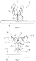
- the metal profile 1 shown in cross section has been produced by forming from a metal sheet and has a substantially T-shaped profile cross section.
- the two ends of the sheet metal form it lateral boundaries of a groove 3, which in the present case is trapezoidal in cross section.
- the trapezoidal cross-section of the groove 3 facilitates the insertion of an insulating profile 2 in order to form a composite profile according to FIG Fig. 3 or the Fig. 4 to get.
- the profile sections 3.1, 3.4 laterally delimiting the groove 3 are folded over at their ends to form a groove 6 on the groove side.
- the fold 6 facilitates the production of a positive connection between the metal profile 1 and the insulating profile 2, since the area of the fold 6 can be placed around an end outer contour of the insulating profile 2 in such a way that the fold 6 engages behind the outer contour.
- the illustrated metal profile 1 have a structure 7 in the form of knurling on their groove-side surface (see dashed line, which is intended to clarify the area of the knurling).
- the knurling counteracts relative movements of an insulating profile 2 received in the groove 3 and connected to the metal profile 1 in a non-positive and / or form-fitting manner with respect to the metal profile 1.
- the profile sections 3.1, 3.2, 3.3, 3.4 delimiting the groove 3 comprise the profile sections 3..2, 3.3, which form a groove base of the groove 3.
- the profile sections 3.2, 3.3 forming the groove base are followed by profile sections 5.1, 5.2, which lie on top of one another in some areas, namely in a common contact area 4, and thus form a web 5. Outside the common contact area 4, the profile sections 5.1, 5.2 delimit a gap 8, which is open to accommodate a weld 10 towards the groove 3 (in the Figs. 1 and 2 the metal profile 1 is already shown with the weld seam 10 set).
- the profile sections 5.1, 5.2 forming the web 5 are followed by further profile sections 9.1, 9.2, 9.3, which form a flange 9 which is arranged perpendicular to the web 5.
- the profile sections 9.1, 9.2, 9.3 also lie on top of one another, so that a high degree of dimensional rigidity is achieved through the double-lying material.
- the sheet metal of the metal profile 1 has a sheet thickness S ′ which is reduced compared to the sheet thickness S in the area of the profile sections 3.2, 3.3 forming the groove base.
- the reduced sheet thickness S ' is in the present case 1.3 mm, while the sheet thickness S is 1.5 mm.
- the areas with reduced sheet metal thickness S ′ create predetermined bending points which facilitate a force-fitting and / or form-fitting connection of the metal profile 1 with an insulating profile 2.
- the force required to produce the desired force and / or form fit through plastic deformation is reduced.
- the plastic deformation can essentially be limited to the area of the predetermined bending points, so that the profile sections 3.1, 3.4 laterally delimiting the groove 3 are not plastically deformed.
- a composite profile can be achieved which has a high degree of dimensional accuracy.
- the profile sections 5.1, 5.2 forming the web 5 in the area of the gap 8 also have a reduced sheet metal thickness S ′.
- the sheet thickness reduction is used to form the gap 8. Since a weld 10 is arranged in the gap 8, which connects the two profile sections 5.1, 5.2, it is ensured that these two profile sections 5.1, 5.2 are not subject to any deformation if the metal profile 1 with an insulating profile 2 is connected non-positively and / or positively by plastic deformation.
- the weld seam 10 also prevents the groove 3 from bending open.
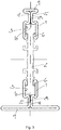
- a preferred embodiment of a composite profile produced using a metal profile 1 according to the invention is that Fig. 3 refer to.
- the composite profile comprises the metal profile 1 of the Fig. 1 and a second metal profile 1, which differs from the first metal profile 1 only in that it has a flange 9 with a smaller width.
- an insulating profile 2 is arranged between the two metal profiles 1. At its two ends, the insulating profile 2 has an outer contour that is received in the groove 3 of the respective metal profile 1 and is connected to it in a non-positive and / or positive manner.
- the composite profile shown is used in particular to produce a window or door element.
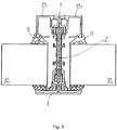
- a window or door element is exemplified in Fig. 4 shown.
- the present consists of a pane of glass.
- the sealing profiles 11 are arranged in the area of the web 5 and supported on the flange 9. Further sealing profiles 11 are placed on glass holding profiles 13 which are arranged on both sides of the second metal profile 1.
- the glass holding profiles 13 are essentially flush with the flange 9 of the second metal profile 1 and their width is selected such that the face width of the second metal profile 1 including the glass holding profiles 13 corresponds to the face width of the flange 9 of the first metal profile 1.
Landscapes
- Engineering & Computer Science (AREA)
- Civil Engineering (AREA)
- Structural Engineering (AREA)
- Connection Of Plates (AREA)
- Wing Frames And Configurations (AREA)
Claims (12)
- Profilé métallique (1) ayant été fabriqué par formage, en particulier par roulage, à partir d'une tôle métallique et ayant une section transversale de profilé formant une rainure (3) pour un assemblage avec un profilé d'isolation (2), dans lequel la rainure (3) est délimitée par des parties de profilé (3.1, 3.2, 3.3, 3.4) adjacentes à des parties de profilé (5.1, 5.2) qui sont les unes au-dessus des autres au moins dans une zone de contact commune (4),
caractérisé en ce que la tôle métallique du profilé métallique (1) a une épaisseur de tôle (S) qui est réduite au moins dans la zone d'une partie de profilé (3.2, 3.3) formant un fond de rainure, de sorte qu'un emplacement de flexion programmée est créé, lequel emplacement facilite la réalisation d'un assemblage à force et/ou par complémentarité de formes du profilé métallique (1) avec le profilé d'isolation (2). - Profilé métallique (1) selon la revendication 1,
caractérisé en ce que l'épaisseur de tôle (S) de la tôle métallique est réduite d'au moins 10 % au moins dans la zone d'une partie de profilé (3.1, 3.2, 3.3, 3.4) délimitant la rainure (3), dans lequel l'épaisseur de tôle (S) est de préférence comprise entre 1 et 3 mm, de manière plus préférée comprise entre 1 et 2 mm, par exemple égale à 1,5 mm. - Profilé métallique (1) selon l'une des revendications précédentes,
caractérisé en ce que la rainure (3) est formée de manière symétrique en coupe transversale, dans lequel la rainure (3) a de préférence une forme de section transversale sensiblement triangulaire, trapézoïdale ou rectangulaire. - Profilé métallique (1) selon l'une des revendications précédentes,
caractérisé en ce que les extrémités libres de parties de profilé (3.1, 3.4) délimitant latéralement la rainure (3) ont un rabat ou une pliure (6). - Profilé métallique (1) selon l'une des revendications précédentes,
caractérisé en ce qu'au moins une partie de profilé (3.1, 3.2, 3.3, 3.4) délimitant la rainure (3) a une surface côté rainure qui est pourvue, au moins dans certaines zones, d'une texture (7) ayant de préférence la forme d'un moletage. - Profilé métallique (1) selon l'une des revendications précédentes,
caractérisé en ce que les parties de profilé (5.1, 5.2) adjacentes aux parties de profilé (3.1, 3.2, 3.3, 3.4) délimitant la rainure et situées les unes au-dessus des autres au moins dans une zone de contact commune (4) sont assemblées, en particulier soudées ou collées, dans au moins une zone. - Profilé métallique (1) selon l'une des revendications précédentes,
caractérisé en ce que les parties de profilé (5.1, 5.2) adjacentes aux parties de profilé (3.1, 3.2, 3.3, 3.4) délimitant la rainure et situées les unes au-dessus des autres au moins dans une zone de contact commune (4) délimitent un espace (8) ouvert vers la rainure (3) à l'extérieur de leur zone de contact commune (4), dans lequel l'assemblage, en particulier le soudage ou le collage, des parties de profilé (5.1, 5.2) est de préférence réalisé dans la zone de l'espace (8). - Profilé métallique (1) selon l'une des revendications précédentes,
caractérisé en ce que les parties de profilé (5.1, 5.2) adjacentes aux parties de profilé (3.1, 3.2, 3.3, 3.4) délimitant la rainure et situées les unes au-dessus des autres au moins dans une zone de contact commune (4) forment un gradin (5) qui est agencé au centre par rapport à la rainure (3). - Profilé métallique (1) selon l'une des revendications précédentes,
caractérisé en ce que les parties de profilé (5.1, 5.2) adjacentes aux parties de profilé (3.1, 3.2, 3.3, 3.4) délimitant la rainure et situées les unes au-dessus des autres au moins dans une zone de contact commune (4) sont assemblées par l'intermédiaire de parties de profilé supplémentaires (9.1, 9.2, 9.3), dans lequel les parties de profilé supplémentaires (9.1, 9.2, 9.3) forment de préférence au moins une semelle (9) qui est en outre agencée de préférence perpendiculairement au gradin (5). - Profilé composite ayant au moins un profilé métallique (1) selon l'une des revendications précédentes et un profilé d'isolation (2) qui est reçu, dans certaines zones, dans la rainure (3) du profilé métallique (1) et qui est assemblé à force et/ou par complémentarité de formes avec le profilé métallique (1).
- Procédé de fabrication d'un profilé métallique (1) selon l'une des revendications 1 à 9, dans lequel le profilé métallique (1) est fabriqué par formage, en particulier par roulage, à partir d'une tôle métallique ayant une épaisseur de tôle (S), caractérisé en ce que pour former une partie de profilé (3.2, 3.3) délimitant la rainure (3) avant le formage, en particulier avant le roulage, l'épaisseur de tôle (S) de la tôle métallique est réduite au moins dans une zone par déformation plastique, en particulier par étirage, de sorte que la tôle métallique a au moins deux épaisseurs de tôle différentes.
- Procédé selon la revendication 11,
caractérisé en ce que l'épaisseur de tôle (S) de la tôle métallique, qui est de préférence comprise entre 1 et 3 mm, de manière plus préférée comprise entre 1 et 2 mm, par exemple égale à 1,5 mm, est réduite d'au moins 10 % dans au moins une zone.
Priority Applications (1)
| Application Number | Priority Date | Filing Date | Title |
|---|---|---|---|
| EP15152188.7A EP3048232B1 (fr) | 2015-01-22 | 2015-01-22 | Profilé métallique, profilé composite avec un tel profilé métallique ainsi que procédé de fabrication du profilé métallique |
Applications Claiming Priority (1)
| Application Number | Priority Date | Filing Date | Title |
|---|---|---|---|
| EP15152188.7A EP3048232B1 (fr) | 2015-01-22 | 2015-01-22 | Profilé métallique, profilé composite avec un tel profilé métallique ainsi que procédé de fabrication du profilé métallique |
Publications (2)
| Publication Number | Publication Date |
|---|---|
| EP3048232A1 EP3048232A1 (fr) | 2016-07-27 |
| EP3048232B1 true EP3048232B1 (fr) | 2020-08-19 |
Family
ID=52358688
Family Applications (1)
| Application Number | Title | Priority Date | Filing Date |
|---|---|---|---|
| EP15152188.7A Active EP3048232B1 (fr) | 2015-01-22 | 2015-01-22 | Profilé métallique, profilé composite avec un tel profilé métallique ainsi que procédé de fabrication du profilé métallique |
Country Status (1)
| Country | Link |
|---|---|
| EP (1) | EP3048232B1 (fr) |
Families Citing this family (1)
| Publication number | Priority date | Publication date | Assignee | Title |
|---|---|---|---|---|
| EP3396096B1 (fr) * | 2017-04-28 | 2020-02-19 | RP Technik GmbH Profilsysteme | Profilé composite et son procédé de fabrication |
Citations (1)
| Publication number | Priority date | Publication date | Assignee | Title |
|---|---|---|---|---|
| DE7617158U1 (fr) * | 1900-01-01 | Mannesmann Ag, 4000 Duesseldorf |
Family Cites Families (4)
| Publication number | Priority date | Publication date | Assignee | Title |
|---|---|---|---|---|
| DE3503708A1 (de) | 1983-09-09 | 1986-08-14 | Josef Gartner & Co, 8883 Gundelfingen | Verfahren zur herstellung eines verbundprofils |
| US6640605B2 (en) * | 1999-01-27 | 2003-11-04 | Milgo Industrial, Inc. | Method of bending sheet metal to form three-dimensional structures |
| DE102008011200A1 (de) * | 2008-02-26 | 2009-09-03 | Rp Technik Gmbh Profilsysteme | Verbundprofil, insbesondere für ein Fenster-, Tür- oder Fassadensystem |
| CH704363A1 (de) | 2011-01-14 | 2012-07-31 | Jansen Ag | Verbundprofil für Fenster, Türen und Fassaden sowie Verfahren zu dessen Herstellung. |
-
2015
- 2015-01-22 EP EP15152188.7A patent/EP3048232B1/fr active Active
Patent Citations (1)
| Publication number | Priority date | Publication date | Assignee | Title |
|---|---|---|---|---|
| DE7617158U1 (fr) * | 1900-01-01 | Mannesmann Ag, 4000 Duesseldorf |
Also Published As
| Publication number | Publication date |
|---|---|
| EP3048232A1 (fr) | 2016-07-27 |
Similar Documents
| Publication | Publication Date | Title |
|---|---|---|
| EP1479842B1 (fr) | Profilé creux | |
| EP2476853B1 (fr) | Profil composite pour fenêtres, portes et façades et son procédé de fabrication | |
| EP2236720A1 (fr) | Elément de profilé pour fenêtres ou portes | |
| DE3236357A1 (de) | Verfahren zum verbinden der metallischen innen- und aussenteile eines verbundprofils mit einem isoliersteg aus kunststoff | |
| EP3301012A1 (fr) | Dispositif de raccordement pour raccordement aérodynamique lisse de deux éléments profilés et dispositif de formation de dispositif de raccordement | |
| DE102015114943B4 (de) | Verfahren zur Herstellung eines geschlossenen Hohlprofils für eine Fahrzeugachse | |
| DE3032939A1 (de) | Rahmenprofil fuer fenster, tueren o.dgl. aus einem kunststoffhauptprofil und einem metallverblendprofil und verfahren zur herstellung von rahmen aus diesen rahmenprofilen | |
| DE3634793A1 (de) | Verfahren zum verschweissen von kunststoffprofilen | |
| DE102008047331B4 (de) | Verfahren zur Herstellung eines Verbundprofils | |
| EP3354835A1 (fr) | Profil composite | |
| EP2325431B1 (fr) | Procédé de fabrication d'un profilé composite à isolation thermique | |
| EP3048232B1 (fr) | Profilé métallique, profilé composite avec un tel profilé métallique ainsi que procédé de fabrication du profilé métallique | |
| DE102008054159B4 (de) | Verfahren zum Herstellen einer Klemmleiste | |
| EP3048231B1 (fr) | Profilé métallique, profilé composite avec un tel profilé métallique ainsi que procédé de fabrication du profilé métallique | |
| EP3015635B1 (fr) | Profile composite pour des portes, fenetres ou elements de façade | |
| EP3396096B1 (fr) | Profilé composite et son procédé de fabrication | |
| DE29517375U1 (de) | Verbundprofil | |
| EP3423659B1 (fr) | Profilé composite pour porte, fenêtre ou façade et procédé de fabrication dudit profilé composite | |
| DE102013005295A1 (de) | Verfahren und Werkzeug zum Verbinden eines Blechbauteils mit einem weiteren Bauteil | |
| EP3055476B1 (fr) | Profilé composite, bande de renforcement pour profilé composite et procédé permettant de produire un profilé composite | |
| DD202333A5 (de) | Gehrungseckverbindung fuer profilstaeben zusammengesetzte rahmen, insb. fenster- und tuerrahmen und dgl. | |
| EP2030825B1 (fr) | Procédé de fabrication d'une borne plate | |
| DE3920676A1 (de) | Verfahren zum verbinden von werkstuecken | |
| DE102006040519B4 (de) | Verfahren zur Herstellung einer Stromschiene | |
| EP1712307B1 (fr) | Méthode d'obtention d'une pièce en tôle comprenant au moins un bord au moins partiellement roulé et pièce obtenue suivant cette méthode. |
Legal Events
| Date | Code | Title | Description |
|---|---|---|---|
| PUAI | Public reference made under article 153(3) epc to a published international application that has entered the european phase |
Free format text: ORIGINAL CODE: 0009012 |
|
| AK | Designated contracting states |
Kind code of ref document: A1 Designated state(s): AL AT BE BG CH CY CZ DE DK EE ES FI FR GB GR HR HU IE IS IT LI LT LU LV MC MK MT NL NO PL PT RO RS SE SI SK SM TR |
|
| AX | Request for extension of the european patent |
Extension state: BA ME |
|
| STAA | Information on the status of an ep patent application or granted ep patent |
Free format text: STATUS: REQUEST FOR EXAMINATION WAS MADE |
|
| 17P | Request for examination filed |
Effective date: 20170112 |
|
| RBV | Designated contracting states (corrected) |
Designated state(s): AL AT BE BG CH CY CZ DE DK EE ES FI FR GB GR HR HU IE IS IT LI LT LU LV MC MK MT NL NO PL PT RO RS SE SI SK SM TR |
|
| STAA | Information on the status of an ep patent application or granted ep patent |
Free format text: STATUS: EXAMINATION IS IN PROGRESS |
|
| 17Q | First examination report despatched |
Effective date: 20180122 |
|
| GRAP | Despatch of communication of intention to grant a patent |
Free format text: ORIGINAL CODE: EPIDOSNIGR1 |
|
| STAA | Information on the status of an ep patent application or granted ep patent |
Free format text: STATUS: GRANT OF PATENT IS INTENDED |
|
| INTG | Intention to grant announced |
Effective date: 20200327 |
|
| GRAS | Grant fee paid |
Free format text: ORIGINAL CODE: EPIDOSNIGR3 |
|
| GRAA | (expected) grant |
Free format text: ORIGINAL CODE: 0009210 |
|
| STAA | Information on the status of an ep patent application or granted ep patent |
Free format text: STATUS: THE PATENT HAS BEEN GRANTED |
|
| AK | Designated contracting states |
Kind code of ref document: B1 Designated state(s): AL AT BE BG CH CY CZ DE DK EE ES FI FR GB GR HR HU IE IS IT LI LT LU LV MC MK MT NL NO PL PT RO RS SE SI SK SM TR |
|
| REG | Reference to a national code |
Ref country code: CH Ref legal event code: EP |
|
| REG | Reference to a national code |
Ref country code: DE Ref legal event code: R096 Ref document number: 502015013250 Country of ref document: DE |
|
| REG | Reference to a national code |
Ref country code: AT Ref legal event code: REF Ref document number: 1304121 Country of ref document: AT Kind code of ref document: T Effective date: 20200915 |
|
| REG | Reference to a national code |
Ref country code: IE Ref legal event code: FG4D Free format text: LANGUAGE OF EP DOCUMENT: GERMAN |
|
| REG | Reference to a national code |
Ref country code: LT Ref legal event code: MG4D |
|
| REG | Reference to a national code |
Ref country code: NL Ref legal event code: MP Effective date: 20200819 |
|
| PG25 | Lapsed in a contracting state [announced via postgrant information from national office to epo] |
Ref country code: SE Free format text: LAPSE BECAUSE OF FAILURE TO SUBMIT A TRANSLATION OF THE DESCRIPTION OR TO PAY THE FEE WITHIN THE PRESCRIBED TIME-LIMIT Effective date: 20200819 Ref country code: FI Free format text: LAPSE BECAUSE OF FAILURE TO SUBMIT A TRANSLATION OF THE DESCRIPTION OR TO PAY THE FEE WITHIN THE PRESCRIBED TIME-LIMIT Effective date: 20200819 Ref country code: BG Free format text: LAPSE BECAUSE OF FAILURE TO SUBMIT A TRANSLATION OF THE DESCRIPTION OR TO PAY THE FEE WITHIN THE PRESCRIBED TIME-LIMIT Effective date: 20201119 Ref country code: NO Free format text: LAPSE BECAUSE OF FAILURE TO SUBMIT A TRANSLATION OF THE DESCRIPTION OR TO PAY THE FEE WITHIN THE PRESCRIBED TIME-LIMIT Effective date: 20201119 Ref country code: PT Free format text: LAPSE BECAUSE OF FAILURE TO SUBMIT A TRANSLATION OF THE DESCRIPTION OR TO PAY THE FEE WITHIN THE PRESCRIBED TIME-LIMIT Effective date: 20201221 Ref country code: GR Free format text: LAPSE BECAUSE OF FAILURE TO SUBMIT A TRANSLATION OF THE DESCRIPTION OR TO PAY THE FEE WITHIN THE PRESCRIBED TIME-LIMIT Effective date: 20201120 Ref country code: HR Free format text: LAPSE BECAUSE OF FAILURE TO SUBMIT A TRANSLATION OF THE DESCRIPTION OR TO PAY THE FEE WITHIN THE PRESCRIBED TIME-LIMIT Effective date: 20200819 Ref country code: LT Free format text: LAPSE BECAUSE OF FAILURE TO SUBMIT A TRANSLATION OF THE DESCRIPTION OR TO PAY THE FEE WITHIN THE PRESCRIBED TIME-LIMIT Effective date: 20200819 |
|
| PG25 | Lapsed in a contracting state [announced via postgrant information from national office to epo] |
Ref country code: IS Free format text: LAPSE BECAUSE OF FAILURE TO SUBMIT A TRANSLATION OF THE DESCRIPTION OR TO PAY THE FEE WITHIN THE PRESCRIBED TIME-LIMIT Effective date: 20201219 Ref country code: NL Free format text: LAPSE BECAUSE OF FAILURE TO SUBMIT A TRANSLATION OF THE DESCRIPTION OR TO PAY THE FEE WITHIN THE PRESCRIBED TIME-LIMIT Effective date: 20200819 Ref country code: PL Free format text: LAPSE BECAUSE OF FAILURE TO SUBMIT A TRANSLATION OF THE DESCRIPTION OR TO PAY THE FEE WITHIN THE PRESCRIBED TIME-LIMIT Effective date: 20200819 Ref country code: RS Free format text: LAPSE BECAUSE OF FAILURE TO SUBMIT A TRANSLATION OF THE DESCRIPTION OR TO PAY THE FEE WITHIN THE PRESCRIBED TIME-LIMIT Effective date: 20200819 Ref country code: LV Free format text: LAPSE BECAUSE OF FAILURE TO SUBMIT A TRANSLATION OF THE DESCRIPTION OR TO PAY THE FEE WITHIN THE PRESCRIBED TIME-LIMIT Effective date: 20200819 |
|
| PG25 | Lapsed in a contracting state [announced via postgrant information from national office to epo] |
Ref country code: CZ Free format text: LAPSE BECAUSE OF FAILURE TO SUBMIT A TRANSLATION OF THE DESCRIPTION OR TO PAY THE FEE WITHIN THE PRESCRIBED TIME-LIMIT Effective date: 20200819 Ref country code: DK Free format text: LAPSE BECAUSE OF FAILURE TO SUBMIT A TRANSLATION OF THE DESCRIPTION OR TO PAY THE FEE WITHIN THE PRESCRIBED TIME-LIMIT Effective date: 20200819 Ref country code: RO Free format text: LAPSE BECAUSE OF FAILURE TO SUBMIT A TRANSLATION OF THE DESCRIPTION OR TO PAY THE FEE WITHIN THE PRESCRIBED TIME-LIMIT Effective date: 20200819 Ref country code: SM Free format text: LAPSE BECAUSE OF FAILURE TO SUBMIT A TRANSLATION OF THE DESCRIPTION OR TO PAY THE FEE WITHIN THE PRESCRIBED TIME-LIMIT Effective date: 20200819 Ref country code: EE Free format text: LAPSE BECAUSE OF FAILURE TO SUBMIT A TRANSLATION OF THE DESCRIPTION OR TO PAY THE FEE WITHIN THE PRESCRIBED TIME-LIMIT Effective date: 20200819 |
|
| REG | Reference to a national code |
Ref country code: DE Ref legal event code: R097 Ref document number: 502015013250 Country of ref document: DE |
|
| PG25 | Lapsed in a contracting state [announced via postgrant information from national office to epo] |
Ref country code: ES Free format text: LAPSE BECAUSE OF FAILURE TO SUBMIT A TRANSLATION OF THE DESCRIPTION OR TO PAY THE FEE WITHIN THE PRESCRIBED TIME-LIMIT Effective date: 20200819 Ref country code: AL Free format text: LAPSE BECAUSE OF FAILURE TO SUBMIT A TRANSLATION OF THE DESCRIPTION OR TO PAY THE FEE WITHIN THE PRESCRIBED TIME-LIMIT Effective date: 20200819 |
|
| PLBE | No opposition filed within time limit |
Free format text: ORIGINAL CODE: 0009261 |
|
| STAA | Information on the status of an ep patent application or granted ep patent |
Free format text: STATUS: NO OPPOSITION FILED WITHIN TIME LIMIT |
|
| PG25 | Lapsed in a contracting state [announced via postgrant information from national office to epo] |
Ref country code: SK Free format text: LAPSE BECAUSE OF FAILURE TO SUBMIT A TRANSLATION OF THE DESCRIPTION OR TO PAY THE FEE WITHIN THE PRESCRIBED TIME-LIMIT Effective date: 20200819 |
|
| 26N | No opposition filed |
Effective date: 20210520 |
|
| PG25 | Lapsed in a contracting state [announced via postgrant information from national office to epo] |
Ref country code: IT Free format text: LAPSE BECAUSE OF FAILURE TO SUBMIT A TRANSLATION OF THE DESCRIPTION OR TO PAY THE FEE WITHIN THE PRESCRIBED TIME-LIMIT Effective date: 20200819 |
|
| PG25 | Lapsed in a contracting state [announced via postgrant information from national office to epo] |
Ref country code: MC Free format text: LAPSE BECAUSE OF FAILURE TO SUBMIT A TRANSLATION OF THE DESCRIPTION OR TO PAY THE FEE WITHIN THE PRESCRIBED TIME-LIMIT Effective date: 20200819 Ref country code: SI Free format text: LAPSE BECAUSE OF FAILURE TO SUBMIT A TRANSLATION OF THE DESCRIPTION OR TO PAY THE FEE WITHIN THE PRESCRIBED TIME-LIMIT Effective date: 20200819 |
|
| REG | Reference to a national code |
Ref country code: CH Ref legal event code: PL |
|
| PG25 | Lapsed in a contracting state [announced via postgrant information from national office to epo] |
Ref country code: LU Free format text: LAPSE BECAUSE OF NON-PAYMENT OF DUE FEES Effective date: 20210122 |
|
| REG | Reference to a national code |
Ref country code: BE Ref legal event code: MM Effective date: 20210131 |
|
| PG25 | Lapsed in a contracting state [announced via postgrant information from national office to epo] |
Ref country code: LI Free format text: LAPSE BECAUSE OF NON-PAYMENT OF DUE FEES Effective date: 20210131 Ref country code: CH Free format text: LAPSE BECAUSE OF NON-PAYMENT OF DUE FEES Effective date: 20210131 |
|
| PG25 | Lapsed in a contracting state [announced via postgrant information from national office to epo] |
Ref country code: IE Free format text: LAPSE BECAUSE OF NON-PAYMENT OF DUE FEES Effective date: 20210122 |
|
| REG | Reference to a national code |
Ref country code: AT Ref legal event code: MM01 Ref document number: 1304121 Country of ref document: AT Kind code of ref document: T Effective date: 20210122 |
|
| PG25 | Lapsed in a contracting state [announced via postgrant information from national office to epo] |
Ref country code: AT Free format text: LAPSE BECAUSE OF NON-PAYMENT OF DUE FEES Effective date: 20210122 |
|
| PG25 | Lapsed in a contracting state [announced via postgrant information from national office to epo] |
Ref country code: BE Free format text: LAPSE BECAUSE OF NON-PAYMENT OF DUE FEES Effective date: 20210131 |
|
| PG25 | Lapsed in a contracting state [announced via postgrant information from national office to epo] |
Ref country code: HU Free format text: LAPSE BECAUSE OF FAILURE TO SUBMIT A TRANSLATION OF THE DESCRIPTION OR TO PAY THE FEE WITHIN THE PRESCRIBED TIME-LIMIT; INVALID AB INITIO Effective date: 20150122 |
|
| PG25 | Lapsed in a contracting state [announced via postgrant information from national office to epo] |
Ref country code: CY Free format text: LAPSE BECAUSE OF FAILURE TO SUBMIT A TRANSLATION OF THE DESCRIPTION OR TO PAY THE FEE WITHIN THE PRESCRIBED TIME-LIMIT Effective date: 20200819 |
|
| P01 | Opt-out of the competence of the unified patent court (upc) registered |
Effective date: 20230616 |
|
| PG25 | Lapsed in a contracting state [announced via postgrant information from national office to epo] |
Ref country code: MK Free format text: LAPSE BECAUSE OF FAILURE TO SUBMIT A TRANSLATION OF THE DESCRIPTION OR TO PAY THE FEE WITHIN THE PRESCRIBED TIME-LIMIT Effective date: 20200819 |
|
| REG | Reference to a national code |
Ref country code: DE Ref legal event code: R081 Ref document number: 502015013250 Country of ref document: DE Owner name: JANSEN AG, OBERRIET, CH Free format text: FORMER OWNER: RP TECHNIK GMBH PROFILSYSTEME, 59199 BOENEN, DE Ref country code: DE Ref legal event code: R081 Ref document number: 502015013250 Country of ref document: DE Owner name: JANSEN AG, CH Free format text: FORMER OWNER: RP TECHNIK GMBH PROFILSYSTEME, 59199 BOENEN, DE |
|
| PG25 | Lapsed in a contracting state [announced via postgrant information from national office to epo] |
Ref country code: TR Free format text: LAPSE BECAUSE OF FAILURE TO SUBMIT A TRANSLATION OF THE DESCRIPTION OR TO PAY THE FEE WITHIN THE PRESCRIBED TIME-LIMIT Effective date: 20200819 |
|
| REG | Reference to a national code |
Ref country code: DE Ref legal event code: R081 Ref document number: 502015013250 Country of ref document: DE Owner name: JANSEN AG, OBERRIET, CH Free format text: FORMER OWNER: JANSEN AG, OBERRIET, CH |
|
| PG25 | Lapsed in a contracting state [announced via postgrant information from national office to epo] |
Ref country code: MT Free format text: LAPSE BECAUSE OF FAILURE TO SUBMIT A TRANSLATION OF THE DESCRIPTION OR TO PAY THE FEE WITHIN THE PRESCRIBED TIME-LIMIT Effective date: 20200819 |
|
| REG | Reference to a national code |
Ref country code: GB Ref legal event code: 732E Free format text: REGISTERED BETWEEN 20251023 AND 20251029 |
|
| PGFP | Annual fee paid to national office [announced via postgrant information from national office to epo] |
Ref country code: GB Payment date: 20260123 Year of fee payment: 12 |
|
| PGFP | Annual fee paid to national office [announced via postgrant information from national office to epo] |
Ref country code: DE Payment date: 20260131 Year of fee payment: 12 |
|
| PGFP | Annual fee paid to national office [announced via postgrant information from national office to epo] |
Ref country code: FR Payment date: 20260123 Year of fee payment: 12 |