EP3841475B1 - Verfahren und vorrichtung zur verifizierung eines software-systems - Google Patents
Verfahren und vorrichtung zur verifizierung eines software-systems Download PDFInfo
- Publication number
- EP3841475B1 EP3841475B1 EP18827112.6A EP18827112A EP3841475B1 EP 3841475 B1 EP3841475 B1 EP 3841475B1 EP 18827112 A EP18827112 A EP 18827112A EP 3841475 B1 EP3841475 B1 EP 3841475B1
- Authority
- EP
- European Patent Office
- Prior art keywords
- software system
- verification
- state
- simulation
- software
- Prior art date
- Legal status (The legal status is an assumption and is not a legal conclusion. Google has not performed a legal analysis and makes no representation as to the accuracy of the status listed.)
- Active
Links
Images


Classifications
-
- G—PHYSICS
- G06—COMPUTING OR CALCULATING; COUNTING
- G06F—ELECTRIC DIGITAL DATA PROCESSING
- G06F11/00—Error detection; Error correction; Monitoring
- G06F11/36—Prevention of errors by analysis, debugging or testing of software
- G06F11/3604—Analysis of software for verifying properties of programs
- G06F11/3608—Analysis of software for verifying properties of programs using formal methods, e.g. model checking, abstract interpretation
-
- G—PHYSICS
- G06—COMPUTING OR CALCULATING; COUNTING
- G06F—ELECTRIC DIGITAL DATA PROCESSING
- G06F11/00—Error detection; Error correction; Monitoring
- G06F11/36—Prevention of errors by analysis, debugging or testing of software
- G06F11/3668—Testing of software
- G06F11/3672—Test management
- G06F11/3684—Test management for test design, e.g. generating new test cases
-
- G—PHYSICS
- G06—COMPUTING OR CALCULATING; COUNTING
- G06F—ELECTRIC DIGITAL DATA PROCESSING
- G06F11/00—Error detection; Error correction; Monitoring
- G06F11/36—Prevention of errors by analysis, debugging or testing of software
- G06F11/3698—Environments for analysis, debugging or testing of software
Definitions
- the present disclosure relates generally to a field of design and development of software systems, and more particularly relates to a method and apparatus for verifying a software system.
- Software systems such as reactive systems which process input data at each step using a software logic and produce an output command.
- An example of the reactive system is adaptive cruise controller for a vehicle.
- the adaptive cruise controller takes input data such as distance to a next vehicle, current speed of vehicle, desired speed, and produces output command to a throttle.
- EP2447848 discloses a technique for bringing a software system to a desired starting state among several options and executing therefrom a software verification by symbolic execution.
- a data processing apparatus for verifying a software system includes a processing unit, and a memory unit communicatively coupled to the processing unit.
- the memory unit includes a simulation module configured to perform simulation of a software system (e.g., a reactive system) for a first set of steps based on a first set of input values. For example, the simulation of the software system is performed using a closed loop simulation technique.
- the memory unit includes a verification module configured to determine a state of the software system in which verification of the software system is to be initiated, and initiate verification of the software system in the determined state.
- the verification module is configured to perform verification of the software system for a second set of steps based on a second set of input values, and a certain internal state of the software system, and output results of the verification of the software system on a display unit.
- the verification of the software system is performed using a bounded-model checking technique.
- the verification module is configured to generate a plurality of test vectors for testing the software system. It can be noted that, the first set of steps are greater than the second set of steps whereas the first set of input values are less than the second set of input values.
- the simulation module may be configured to determine a set of states associated with the software system during the first set of steps performed by the software system, and store values of state variables associated with each state of the software system in a verification database.
- the verification module is configured to instantaneously determine a state of the set of states in which the software system starts operating in an operation mode. Additionally, the verification module is configured to initialize the software system in the determined state using values of the state variables associated with the determined state, and initiate verification of the initialized software system in the determined state.
- the verification module may be configured to parse programming language statements associated with the software system, generate a control flow graph based on the parsed programming language statements, and determine whether any of the second set of input values are violated.
- a method of verifying a software system includes performing simulation of a software system for a first set of steps based on a first set of input values, and determining a state of the software system in which verification of the software system is to be initiated.
- the simulation of the software system may be performed using a closed loop simulation technique.
- the method may include initiating verification of the software system at the determined state, and performing verification of the software system for a second set of steps based on a second set of input values.
- the verification of the software system may be performed using a bounded-model checking technique.
- the method includes outputting results of the verification of the software system on a display unit.
- the method may include generating a plurality of test vectors capable of testing the software system.
- the method may include determining a set of states associated with the software system during the first set of steps performed by the software system, and storing values of state variables associated with each state of the software system in a verification database.
- the method may include instantaneously determining a state from the set of states in which the software system starts operating in an operation mode.
- the method may include initializing the software system in the determined state using values of the state variables associated with the determined state, and initiating verification of the initialized software system in the determined state.
- the method may include parsing programming language statements associated with the software system, generating a control flow graph based on the parsed programming language statements, and determining whether any of the second set of input values are violated.
- a non-transitory computer-readable storage medium having machine-readable instructions stored therein, that when executed by a processing unit, cause the processing unit to perform a method described above.
- a method and apparatus are provided to verify a software system in an appropriate state based on a plurality of input values.
- the software system includes software components which are responsible for performing one or more functions associated with hardware system.
- the hardware system may be a vehicle with an adaptive cruise controller.
- the software system takes inputs from various components of the vehicle such as speed, distance to vehicle in front, etc. and produces a command by processing the inputs.
- the command is processed by another component of the vehicle such as throttle to accelerate or decelerate the vehicle.
- it is important to verify behavior of the software system. Malfunctioning of the software system may lead to unexpected behavior of the adaptive cruise controller and sometimes may lead to vehicle crash.
- the following description describes a data processing system and a method performed by the data processing system to perform verification of the software system during design and development of the software system.
- FIG 1 illustrates a block diagram of a data processing apparatus 100 in which an embodiment can be implemented, for example, as a data processing apparatus particularly configured by software or otherwise to perform the processes as described herein.
- the data processing apparatus 100 may be a personal computer, a laptop computer, a tablet, smart phone, and the like.
- the data processing apparatus 100 includes a processing unit 102, an accessible memory 104, a storage unit 106, an input unit 108, a display unit 110, and a bus 112.
- the processing unit 102 means any type of computational circuit, such as, but not limited to, a microprocessor, microcontroller, complex instruction set computing microprocessor, reduced instruction set computing microprocessor, very long instruction word microprocessor, explicitly parallel instruction computing microprocessor, graphics processor, digital signal processor, or any other type of processing circuit.
- the processing unit 102 may also include embedded controllers, such as generic or programmable logic devices or arrays, application specific integrated circuits, single-chip computers, and the like.
- the memory 104 may be volatile memory and non-volatile memory.
- the memory 104 may be coupled for communication with the processing unit 102.
- the processing unit 102 may execute instructions and/or code stored in the memory 104.
- a variety of computer-readable storage media may be stored in and accessed from the memory 104.
- the memory 104 may include any suitable elements for storing data and machine-readable instructions, such as read only memory, random access memory, erasable programmable read only memory, electrically erasable programmable read only memory, a hard drive, a removable media drive for handling compact disks, digital video disks, diskettes, magnetic tape cartridges, memory cards, and the like.
- the memory 104 includes software design and development (SDD) module 114.
- SDD software design and development
- the SDD module 114 includes a simulation module 116 and a verification module 118 stored in the form of machine-readable instructions on any of the above-mentioned storage media and may be in communication to and executed by processing unit 102.
- the SDD module 114 When executed by the processing unit 102, the SDD module 114 causes the processing unit 102 to perform verification of a software system developed by the SDD module 114 and generate test vectors capable of testing the software system.
- the simulation module 116 causes the processing unit 102 to perform simulation of the software system for a first set of steps based on a first set of input values.
- the simulation of the software system enables determining a set of states associated with the software system when the first set of steps are performed by the software system using the first set of input values.
- the simulation of the software system is performed using a plant model from the plant model database 122.
- the plant model represents an environment associated with the software system.
- the verification module 118 causes the processing unit 102 to determine a state of the software system in which verification of the software system is to be initiated.
- the verification module 118 causes the processing unit 102 to initiate verification of the software system in the determined state and perform verification of the software system for second set of steps based on a second set of input values.
- the verification module 118 causes the processing unit 102 to output results of the verification of the software system on the display unit 110. Additionally, the verification module 118 causes the processing unit 102 to generate test vectors for testing the software system. It can be noted that, method steps performed by the processing unit 102 to achieve the above functionality are described in greater detail in FIG 2 and FIG 3 .
- the storage unit 106 may be a non-transitory storage medium which stores a verification database 120 and a plant model database 122.
- the verification database 120 stores values of state variables associated with the set of states determined during simulation of the software system.
- state variables may include mode of ACC (e.g. sport/economic, keep speed, keep distance, low speeds in traffic jams, etc.). In the "keep distance" mode, the ACC must maintain a minimal distance from a vehicle in front.
- mode of ACC e.g. sport/economic, keep speed, keep distance, low speeds in traffic jams, etc.
- Additional state variables in this mode are "minimum distance to keep” (can have different values depending on road conditions, current vehicle speed, driving mode, inertia of the vehicle caused by vehicle and passengers weight, etc.), “health status of ACC” (can have values set by the self-diagnosis system which cross-checks the correct functioning of the ACC), “history of distance to the next vehicle” (values are originating from the sensor after a braking was initiated and are used to adapt the breaking force to the current breaking conditions - e.g. road, variation of the speed of the vehicle in front - such that the breaking "feels smooth" to the driver but ensures the required safety requirements).
- the input unit 108 may include input means such as keypad, touch-sensitive display, camera (such as a camera receiving gesture-based inputs), etc. capable of receiving input signal such as user commands to design, develop, verify, test a software system.
- the display unit 110 may be configured to display a graphical user interface which visualizes the software system along with results of the verification of the software system.
- the bus 112 acts as interconnect between the processing unit 102, the memory 104, the storage unit 106, the input unit 108, and the display unit 110.
- FIG 1 may vary for particular implementations.
- peripheral devices such as an optical disk drive and the like, Local Area Network (LAN)/ Wide Area Network (WAN)/ Wireless (e.g., Wi-Fi) adapter, graphics adapter, disk controller, input/output (I/O) adapter also may be used in addition or in place of the hardware depicted.
- LAN Local Area Network
- WAN Wide Area Network
- Wireless Wireless
- graphics adapter disk controller
- I/O input/output
- I/O input/output
- a data processing apparatus in accordance with an embodiment of the present disclosure includes an operating system employing a graphical user interface.
- the operating system permits multiple display windows to be presented in the graphical user interface simultaneously with each display window providing an interface to a different application or to a different instance of the same application.
- a cursor in the graphical user interface may be manipulated by a user through the pointing device. The position of the cursor may be changed and/or an event such as clicking a mouse button, generated to actuate a desired response.
- One of various commercial operating systems such as a version of Microsoft Windows TM , a product of Microsoft Corporation located in Redmond, Washington may be employed if suitably modified.
- the operating system is modified or created in accordance with the present disclosure as described.
- Disclosed embodiments provide systems and methods that verify software system in an integrated-development environment.
- disclosed techniques perform simulation of a software system, determine a state associated with software system in which verification is initiated, initiate the verification of the software system in the determined state, perform verification of the software system, and output results of the verification of the software system on a display unit.
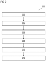
- FIG 2 is a process flowchart 200 illustrating an exemplary method of verifying a software system, according to one embodiment.
- act 202 simulation of a software system is performed for a first set of steps based on a first set of input values.
- the simulation of the software system is performed using closed-loop simulation technique.
- the software system is simulated using a plant model which represent environment of the software system.
- the simulation of the software system is performed for the first set of steps during initialization mode of the software system.
- the simulation of the software system helps to bring the software system into a desired state which enables to perform verification of the software system. For example, the simulation of the software system is performed until a pre-defined condition is met.
- the condition can be (i) an adaptive cruise control (ACC) system of a car is started and initialized or (ii) the ACC system is in "keep distance mode" and has been running on icy roads for 10 minutes and another car in front started breaking violently.
- ACC adaptive cruise control
- a state of the software system in which verification of the software system is to be initiated is determined instantaneously.
- the software system may operate in the initialization mode for some time and later switch to an operation mode (i.e., desired state).
- an operation mode i.e., desired state
- a state in which the software system starts operating in the operation mode is determined. It is desired that the software system is verified in the desired state. Alternatively, it is desired that behavior of the software system is verified after the software system has reached the desired state.
- correct behavior of adaptive cruise control of a car is to be verified upon detecting icy road conditions, high speed of the car and the distance to the vehicle ahead of the car is decreasing rapidly (e.g., presumably due to a full-stop of the front car due to a collision with the vehicle in front of it).
- verification of the software system is initiated at the determined state of the software system. Also, simulation of the software system using a closed-technique is stopped at the determined state. During initiation of the verification, the software system is initialized in the determined state using values of state variables obtained during the simulation of the software system.
- verification of the software system is performed for a second set of steps based on second set of input values. For example, the verification of the software system is performed using a bounded-model checking technique. The verification of the software system includes confirming whether the software system complies with a specification, confirming whether behavior of the software system during the operation mode meets expected behavior and so on. This is achieved by determining whether the second set of input values are violated.
- results of verification of the software system are outputted on a display unit.
- the results of verification may include one or more input values which are violated.
- a plurality of test vectors capable of testing the software system in a desired operation mode is generated.
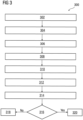
- FIG 3 is a process flowchart 300 illustrating a detailed method of verifying a software system, according to one embodiment.
- a set of states associated with the software system are determined when the first set of steps performed on the software system.
- values of state variables associated with each state of the software system are stored in a verification database.
- a state of the software system during which verification of the software system is to be initiated is determined.
- a state of the set of states in which the software system starts operating in an operation mode is determined. It can be noted that, the values of program variables are initialized symbolically to reflect desired starting point of the verification.
- the software system is initialized in the determined state using the stored values of the state variables associated with the determined state.
- verification of the initialized software system is initiated in the determined state.
- programming language statements associated with the software system are parsed.
- a control flow graph is generated based on the parsed programming language statements.
- FIG 4 is a graphical representation 400 depicting approach applied in verification of a software system, according to one embodiment.
- the verification of a software system with one input port is carried out using two approaches namely: closed-loop simulation technique followed by a bounded-model checking technique.
- simulation of the software system composed with a plant model is performed for N number of steps 406 based on an input value provided via the input port using a closed-loop simulation technique.
- the simulation of the software system enables to reach a certain state in which verification of the software system can be initiated.
- a set of states associated with the software system are determined and values of state variables associated with the set of states are stored. Thereafter, a desired state for verifying the software system is determined.
- the software system is initialized using the values of state variables associated with the determined state.
- a controller of a motor may need thousands of cycles to warm up the engine and reach an operation mode (i.e., desired state).
- an operation mode i.e., desired state
- verification of certain properties of the engine may need to be performed during the operation mode.
- the simulation of the software system helps to start verification in the desired state (i.e., the operation mode of the engine).
- ACC adaptive cruise control
- the ACC system needs hundreds of cycles to initialize car monitoring state from which the ACC system can take control of a braking system of the car.
- a C-level model checker processes programming language statements (e.g., C language statements), and transforms the programming language statements in a symbolic representation (e.g., a control flow graph).
- the C-level model checker determine one or more input values that lead to the violation (abnormal behavior of the software system). This is achieved by traversing through the control flow graph and identify paths in the control flow graph which lead to violations.
- the C-model checker uses a decision procedure to traverse through the control flow graph and identify paths that lead to violations.
- the decision procedure may employ a bit-vector logic including non-linear arithmetic and arrays to solve reachability of paths represented as a Boolean satisfiability problem.
- the graphical representation 400 depicts the approach used in verification of the software system.
- the graphical representation 400 includes an X-axis 404 representing steps performed on the software system during verification of the software system and Y-axis 402 representing a number of inputs used for simulation and verification of the software system.
- the simulation of the software system is performed for N number of steps 406 based on a single input value received at each of the N number of steps 406.
- the graphical representation 400 depicts shape of input space covered by the simulation as a curved line 410.
- the verification of the software system is performed for the M number of steps 408 in a desired state based on a plurality of input values received at each of the N number of steps 406.
- shape of input space 412 covered by the bounded-model checking technique is a region.
- the methods and apparatuses described in FIG 1 to FIG 4 verifies a software system using combination of closed-loop simulation and a bounded-model checking. This is because, during initialization of the software system, simulation of the software system is performed over many steps but cover small part of possible input space.
- simulation of the software system quickly brings the software system to a desired state for verification of the software system. Also, increased coverage in terms of number of steps is achieved.
- bounded-model checking is performed for small number of steps but over a large input space. Thus, possibility of detecting higher number of faulty input values over large input spaces is higher. Also, increased depth of verification is obtained.
- a computer-usable or computer-readable medium can be any apparatus that can contain, store, communicate, propagate, or transport the program for use by or in connection with the instruction execution system, apparatus, or device.
- the medium can be electronic, magnetic, optical, electromagnetic, infrared, or semiconductor system (or apparatus or device) or a propagation mediums in and of themselves as signal carriers are not included in the definition of physical computer-readable medium include a semiconductor or solid state memory, magnetic tape, a removable computer diskette, random access memory (RAM), a read only memory (ROM), a rigid magnetic disk and optical disk such as compact disk read-only memory (CD-ROM), compact disk read/write, and digital versatile disc (DVD).
- RAM random access memory
- ROM read only memory
- CD-ROM compact disk read-only memory
- DVD digital versatile disc
- Both processors and program code for implementing each aspect of the technology can be centralized or distributed (or a combination thereof) as known to those skilled in the art.
Landscapes
- Engineering & Computer Science (AREA)
- Theoretical Computer Science (AREA)
- Computer Hardware Design (AREA)
- Quality & Reliability (AREA)
- Physics & Mathematics (AREA)
- General Engineering & Computer Science (AREA)
- General Physics & Mathematics (AREA)
- Software Systems (AREA)
- Debugging And Monitoring (AREA)
Claims (11)
- Datenverarbeitungsvorrichtung (100) zum Verifizieren eines Softwaresystems mit Softwarekomponenten zum Durchführen einer oder mehrerer Funktionen, die einem Hardwaresystem zugeordnet sind, das in verschiedenen Betriebsmodi betrieben werden kann, wobei jeder Modus eine Mehrzahl von Zustandsvariablen umfasst, umfassend:zumindest eine Verarbeitungseinheit (102); undzumindest eine Speichereinheit (104), die kommunikativ mit der Verarbeitungseinheit (102) gekoppelt ist, wobei die Speichereinheit (104) umfasst:
ein Simulationsmodul (116), das dazu ausgelegt ist:eine Simulation des Softwaresystems für einen ersten Satz von Schritten basierend auf einem ersten Satz von Eingabewerten durchzuführen;einen Satz von Zuständen zu bestimmen, die dem Softwaresystem während des ersten Satzes von Schritten zugeordnet sind, die durch das Softwaresystem durchgeführt werden;Werten von Zustandsvariablen, die jedem Zustand des Softwaresystems zugeordnet sind, in einer Verifizierungsdatenbank zu speichern; undein Verifizierungsmodul (118), das dazu ausgelegt ist:einen Zustand des Softwaresystems zu bestimmen, in dem eine Verifizierung des Softwaresystems initiiert werden soll, wobei die Bestimmung des Zustands des Softwaresystems, in dem die Verifizierung des Softwaresystems zu initiieren ist, das sofortige Bestimmen eines gewünschten Zustands aus dem Satz von Zuständen umfasst, in denen das Softwaresystem in einem Betriebsmodus entsprechend dem gewünschten Zustand zu arbeiten beginnt;das Softwaresystems in dem bestimmten Zustand unter Verwendung von Werten der Zustandsvariablen, die dem in der Verifizierungsdatenbank gespeicherten bestimmten Zustand zugeordnet sind, zu initiieren;die Verifizierung des initialisierten Softwaresystems in dem bestimmten Zustand zu initiieren;eine Verifizierung des Softwaresystems für einen zweiten Satz von Schritten basierend auf einem zweiten Satz von Eingabewerten durchzuführen; undErgebnisse der Verifizierung des Softwaresystems auf einer Anzeigeeinheit (110) auszugeben,wobei das Verifizierungsmodul (118) ferner dazu ausgelegt ist:die dem Softwaresystem zugeordneten Aussagen der Programmiersprache zu parsen;einen Steuerflussgraphen basierend auf den geparsten Aussagen der Programmiersprache zu erzeugen; undzu bestimmen, ob einer der Eingabewerte aus dem zweiten Satz zu einer Verletzung einer Vorgabe des Softwaresystems führt. - Datenverarbeitungsvorrichtung (100) nach Anspruch 1, wobei das Verifizierungsmodul (118) dazu ausgelegt ist, eine Mehrzahl von Testvektoren zum Testen des Softwaresystems zu erzeugen.
- Datenverarbeitungsvorrichtung (100) nach Anspruch 1 oder 2, wobei das Simulationsmodul (116) dazu ausgelegt ist, die Simulation des Softwaresystems unter Verwendung einer Closed-Loop-Simulationstechnik durchzuführen.
- Datenverarbeitungsvorrichtung (100) nach Anspruch 1 oder 2, wobei das Verifizierungsmodul (118) dazu ausgelegt ist, die Verifizierung des Softwaresystems unter Verwendung einer beschränkten Modell-Prüftechnik durchzuführen.
- Verfahren zum Verifizieren eines Softwaresystems mit Softwarekomponenten zum Durchführen einer oder mehrerer Funktionen, die einem Hardwaresystem zugeordnet sind, das in verschiedenen Betriebsmodi betrieben werden kann, wobei jeder Modus eine Mehrzahl von Zustandsvariablen umfasst, umfassend:Durchführen, durch eine Datenverarbeitungsvorrichtung (100), einer Simulation eines Softwaresystems für einen ersten Satz von Schritten basierend auf einem ersten Satz von Eingabewerten;Bestimmen, durch die Datenverarbeitungsvorrichtung (100), eines Zustands des Softwaresystems, in dem eine Verifizierung des Softwaresystems zu initiieren ist;Bestimmen, durch die Datenverarbeitungsvorrichtung (100), eines Satzes von Zuständen, die dem Softwaresystem während des ersten Satzes von Schritten zugeordnet sind, die durch das Softwaresystem durchgeführt werden;Speichern, durch die Datenverarbeitungsvorrichtung (100), von Werten von Zustandsvariablen, die jedem Zustand des Softwaresystems zugeordnet sind, in einer Verifizierungsdatenbank;Bestimmen eines Zustands des Softwaresystems, in dem die Verifizierung des Softwaresystems zu initiieren ist, umfassend das sofortige Bestimmen eines gewünschten Zustands aus dem Satz von Zuständen, in dem das Softwaresystem in einem Betriebsmodus entsprechend dem gewünschten Zustand zu arbeiten beginnt;Initialisieren des Softwaresystems in dem bestimmten Zustand durch die Datenverarbeitungsvorrichtung (100) unter Verwendung von Werten der Zustandsvariablen, die dem in der Verifizierungsdatenbank gespeicherten bestimmten Zustand zugeordnet sind;die Verifizierung des initialisierten Softwaresystems in dem bestimmten Zustand zu initiieren;Durchführen, durch die Datenverarbeitungsvorrichtung (100), einer Verifizierung des Softwaresystems für einen zweiten Satz von Schritten basierend auf einem zweiten Satz von Eingabewerten,Ausgeben, durch die Datenverarbeitungsvorrichtung (100), von Ergebnisse der Verifizierung des Softwaresystems auf einer Anzeigeeinheit (110),wobei das Durchführen der Verifizierung des Softwaresystems umfasst:Parsen der dem Softwaresystem zugeordneten Aussagen der Programmiersprache;Erzeugen eines Steuerflussgraphen basierend auf den geparsten Programmiersprachenanweisungen; undBestimmen, ob einer der Eingabewerte aus dem zweiten Satz zu einer Verletzung einer Vorgabe des Softwaresystems führt.
- Verfahren nach Anspruch 5, ferner umfassend:
Erzeugen, durch die Datenverarbeitungsvorrichtung (100), einer Mehrzahl von Testvektoren, die in der Lage sind, das Softwaresystem zu testen. - Verfahren nach Anspruch 5 oder 6, wobei die Simulation des Softwaresystems unter Verwendung einer Closed-Loop-Simulationstechnik durchgeführt wird.
- Verfahren nach Anspruch 5 oder 6, wobei die Verifizierung des Softwaresystems unter Verwendung einer beschränkten Modell-Prüftechnik durchgeführt wird.
- Nichtflüchtiges computerlesbares Speichermedium mit darin gespeicherten maschinenlesbaren Anweisungen, die, wenn sie durch eine Verarbeitungseinheit (102) ausgeführt werden, die Verarbeitungseinheit (102) veranlassen, ein Verfahren zum Verifizieren eines Softwaresystems durchzuführen, das Softwarekomponenten zum Durchführen einer oder mehrerer Funktionen beinhaltet, die einem Hardwaresystem zugeordnet sind, das in verschiedenen Betriebsmodi betrieben werden kann, wobei jeder Modus eine Mehrzahl von Zustandsvariablen umfasst, wobei das Verfahren umfasst:Durchführen einer Simulation eines Softwaresystems für einen ersten Satz von Schritten basierend auf einem ersten Satz von Eingabewerten;Bestimmen eines Zustands des Softwaresystems, in dem eine Verifizierung des Softwaresystems zu initiieren ist;Bestimmen eines Satzes von Zuständen, die dem Softwaresystem während des ersten Satzes von Schritten zugeordnet sind, die durch das Softwaresystem durchgeführt werden;Speichern von Werten von Zustandsvariablen, die jedem Zustand des Softwaresystems zugeordnet sind, in einer Verifizierungsdatenbank;Bestimmen eines Zustands des Softwaresystems, in dem die Verifizierung des Softwaresystems zu initiieren ist, umfassend das sofortige Bestimmen eines gewünschten Zustands aus dem Satz von Zuständen, in dem das Softwaresystem in einem Betriebsmodus entsprechend dem gewünschten Zustand zu arbeiten beginnt;Initialisieren des Softwaresystems in dem bestimmten Zustand unter Verwendung von Werten der Zustandsvariablen, die dem in der Verifizierungsdatenbank gespeicherten bestimmten Zustand zugeordnet sind;Initialisieren des Verifizierens des initialisierten Softwaresystems in dem bestimmten Zustand;Durchführen der Verifizierung des Softwaresystems für einen zweiten Satz von Schritten basierend auf einem zweiten Satz von Eingabewerten; undAusgeben der Ergebnisse der Verifizierung des Softwaresystems auf einer Anzeigeeinheit,wobei das Durchführen der Verifizierung des Softwaresystems umfasst:Parsen der dem Softwaresystem zugeordneten Aussagen der Programmiersprache;Erzeugen eines Steuerflussgraphen basierend auf den geparsten Programmiersprachenanweisungen; undBestimmen, ob einer des zweiten Satzes von Eingabewerten zu einer Verletzung einer Vorgabe des Softwaresystems führt, wobei die maschinenlesbaren Anweisungen die Verarbeitungseinheit (102) veranlassen, Verfahrensschritte auszuführen, die umfassen:Parsen der dem Softwaresystem zugeordneten Aussagen der Programmiersprache;Erzeugen eines Steuerflussgraphen basierend auf den geparsten Programmiersprachenanweisungen; undBestimmen, ob einer der Eingabewerte aus dem zweiten Satz zu einer Verletzung einer Vorgabe des Softwaresystems führt.
- Speichermedium nach Anspruch 9, wobei die maschinenlesbaren Anweisungen die Verarbeitungseinheit (102) veranlassen, einen Verfahrensschritt durchzuführen, der umfasst:
Erzeugen einer Mehrzahl von Testvektoren, die in der Lage sind, das Softwaresystem zu testen. - Speichermedium nach einem der Ansprüche 9 oder 11, wobei die Simulation des Softwaresystems unter Verwendung einer Closed-Loop-Simulationstechnik durchgeführt wird und wobei die Verifizierung des Softwaresystems unter Verwendung einer beschränkten Modell-Prüftechnik durchgeführt wird.
Applications Claiming Priority (2)
| Application Number | Priority Date | Filing Date | Title |
|---|---|---|---|
| IN201831036644 | 2018-09-28 | ||
| PCT/EP2018/086646 WO2020064139A1 (en) | 2018-09-28 | 2018-12-21 | Method and aparatus for verifying a software system |
Publications (2)
| Publication Number | Publication Date |
|---|---|
| EP3841475A1 EP3841475A1 (de) | 2021-06-30 |
| EP3841475B1 true EP3841475B1 (de) | 2024-02-21 |
Family
ID=64901570
Family Applications (1)
| Application Number | Title | Priority Date | Filing Date |
|---|---|---|---|
| EP18827112.6A Active EP3841475B1 (de) | 2018-09-28 | 2018-12-21 | Verfahren und vorrichtung zur verifizierung eines software-systems |
Country Status (4)
| Country | Link |
|---|---|
| US (1) | US20210342250A1 (de) |
| EP (1) | EP3841475B1 (de) |
| JP (1) | JP7230186B2 (de) |
| WO (1) | WO2020064139A1 (de) |
Families Citing this family (1)
| Publication number | Priority date | Publication date | Assignee | Title |
|---|---|---|---|---|
| DE102020206327A1 (de) * | 2020-05-20 | 2021-11-25 | Robert Bosch Gesellschaft mit beschränkter Haftung | Verfahren und Vorrichtung zum Prüfen eines technischen Systems |
Family Cites Families (21)
| Publication number | Priority date | Publication date | Assignee | Title |
|---|---|---|---|---|
| US5870590A (en) * | 1993-07-29 | 1999-02-09 | Kita; Ronald Allen | Method and apparatus for generating an extended finite state machine architecture for a software specification |
| US5630049A (en) * | 1994-11-30 | 1997-05-13 | Digital Equipment Corporation | Method and apparatus for testing software on a computer network |
| US7272482B2 (en) * | 2002-09-30 | 2007-09-18 | Nissan Motor Co., Ltd. | Preceding-vehicle following control system |
| JP4975544B2 (ja) * | 2007-07-20 | 2012-07-11 | 富士通セミコンダクター株式会社 | シミュレーション装置及びプログラム |
| JP5444724B2 (ja) * | 2009-01-20 | 2014-03-19 | 富士通株式会社 | 検証支援プログラム、情報処理装置および検証支援方法 |
| US8532971B2 (en) * | 2010-01-26 | 2013-09-10 | Nec Laboratories America, Inc. | DPLL-based SAT solver using with application-aware branching |
| US8769500B2 (en) * | 2010-10-29 | 2014-07-01 | Fujitsu Limited | Node computation initialization technique for efficient parallelization of software analysis in a distributed computing environment |
| JP2012099035A (ja) | 2010-11-05 | 2012-05-24 | Fujitsu Ltd | プロセッサの動作検証方法、プロセッサの動作検証装置、及びプロセッサの動作検証プログラム |
| JP5589901B2 (ja) | 2011-03-03 | 2014-09-17 | トヨタ自動車株式会社 | ソフトウェア検証支援装置、ソフトウェア検証支援方法及びソフトウェア検証支援プログラム |
| BR112014022180B1 (pt) * | 2012-03-09 | 2022-08-30 | Honda Motor Co., Ltd | Sistema de simulação de comunicação, método de simulação de comunicação e aparelho de comunicação de veículo |
| JP5987189B2 (ja) | 2012-09-24 | 2016-09-07 | 三菱電機株式会社 | テストケース自動生成装置及びテストケース自動生成プログラム |
| JP5903038B2 (ja) | 2012-12-26 | 2016-04-13 | 株式会社日立製作所 | ソースコード等価性検証装置、および、ソースコード等価性検証方法 |
| JP5864510B2 (ja) * | 2013-10-18 | 2016-02-17 | 富士通株式会社 | 修正プログラム確認方法、修正プログラム確認プログラム、及び情報処理装置 |
| EP2940586B1 (de) * | 2014-04-29 | 2023-03-01 | Hitachi, Ltd. | Verfahren und System zum Testen von Steuerungssoftware eines gesteuerten Systems |
| JP2017058600A (ja) * | 2015-09-18 | 2017-03-23 | 富士通テン株式会社 | 表示制御装置、画像表示システム、及び、表示制御方法 |
| US11719545B2 (en) * | 2016-01-22 | 2023-08-08 | Hyundai Motor Company | Autonomous vehicle component damage and salvage assessment |
| JP2017142554A (ja) | 2016-02-08 | 2017-08-17 | トヨタ自動車株式会社 | 検査装置 |
| CN107918585B (zh) * | 2016-10-07 | 2023-05-02 | 福特全球技术公司 | 用于测试软件程序的方法和装置 |
| US20190155291A1 (en) * | 2016-12-23 | 2019-05-23 | Faraday&Future Inc. | Methods and systems for automated driving system simulation, validation, and implementation |
| US20190129831A1 (en) * | 2017-10-27 | 2019-05-02 | Uber Technologies, Inc. | Autonomous Vehicle Simulation Testing Systems and Methods |
| US10310822B1 (en) * | 2017-11-30 | 2019-06-04 | Dspace Digital Signal Processing And Control Engineering Gmbh | Method and system for simulating a control program |
-
2018
- 2018-12-21 EP EP18827112.6A patent/EP3841475B1/de active Active
- 2018-12-21 JP JP2021517334A patent/JP7230186B2/ja active Active
- 2018-12-21 US US17/280,910 patent/US20210342250A1/en active Pending
- 2018-12-21 WO PCT/EP2018/086646 patent/WO2020064139A1/en not_active Ceased
Non-Patent Citations (1)
| Title |
|---|
| LIEBELT C ED - KNAFL G J: "DESIGNING CONSISTENCY - PRESERVING DATABASE TRANSACTIONS", PROCEEDINGS OF THE ANNUAL INTERNATIONAL COMPUTER SOFTWARE AND APPLICATIONS CONFERENCE. (COMPSAC). ORLANDO, SEPT. 20 - 22, 1989; [PROCEEDINGS OF THE ANNUAL INTERNATIONAL COMPUTER SOFTWARE AND APPLICATIONS CONFERENCE. (COMPSAC)], WASHINGTON, IEEE COMP., vol. CONF. 13, 20 September 1989 (1989-09-20), pages 300 - 307, XP000091520 * |
Also Published As
| Publication number | Publication date |
|---|---|
| JP2022502774A (ja) | 2022-01-11 |
| JP7230186B2 (ja) | 2023-02-28 |
| EP3841475A1 (de) | 2021-06-30 |
| WO2020064139A1 (en) | 2020-04-02 |
| US20210342250A1 (en) | 2021-11-04 |
Similar Documents
| Publication | Publication Date | Title |
|---|---|---|
| US11001143B2 (en) | Dynamically re-configurable displays with reconfigurable regions of interest for safety critical content | |
| US12204825B2 (en) | Function safety and fault management modeling at electrical system level (ESL) | |
| EP3623950B1 (de) | System und verfahren zur verifizierung eines fahrzeugsteuergeräts auf basis einer virtuellen maschine | |
| CN108700633B (zh) | 针对安全并且有保障的汽车应用的超快自主时钟监测电路 | |
| JP7136322B2 (ja) | 人工知能プログラムの実行を管理するための監視制御システム、その方法、および非一時的コンピュータ可読媒体 | |
| US20180150378A1 (en) | Verification of model-driven software architecture | |
| EP2778809A2 (de) | Simulationsverfahren und Systeme für ein Flugzeug | |
| US20240045794A1 (en) | Systems and methods for monitoring progression of software versions and detection of anomalies | |
| EP3841475B1 (de) | Verfahren und vorrichtung zur verifizierung eines software-systems | |
| US20080235473A1 (en) | Protection unit for a programmable data-processing system | |
| KR102122795B1 (ko) | 자율주행차 알고리즘 테스트 방법 | |
| Arab et al. | High-resolution safety verification for evasive obstacle avoidance in autonomous vehicles | |
| EP4177124A1 (de) | Spurwechselverfahren und spurwechselsystem | |
| Zhou et al. | Runtime stealthy perception attacks against dnn-based adaptive cruise control systems | |
| Kaiser et al. | An AEBS use case for model-based system design integrating safety analyses and simulation | |
| EP2990899A1 (de) | Steuerungssysteminspektionsvorrichtung | |
| WO2025261358A1 (zh) | 车辆功能场景的风险评估方法、装置及电子设备 | |
| CN110603546A (zh) | 技术系统以及尤其是自主驾驶车辆的产品成熟度确定 | |
| Wehner et al. | Development of driver assistance systems using virtual hardware-in-the-loop | |
| Friedman et al. | Using model-based design for automotive systems engineering-requirements analysis of the power window example | |
| CN106022137A (zh) | 由tpcm控制power平台可信的实现方法及系统 | |
| JP2018525712A (ja) | プロセッサシステムのプログラムカウンタ構造を保護する方法及び装置並びに中断要求の処理を監視する方法及び装置 | |
| EP4498253A1 (de) | System und verfahren zur verwaltung der prüfung von autonomen fahrzeugen | |
| JP7779420B1 (ja) | 車両ソフトウェア開発のためのシステム、方法、およびコンピュータプログラム | |
| US20260044359A1 (en) | Functional safety system using safety certified real-time operating system and hypervisor |
Legal Events
| Date | Code | Title | Description |
|---|---|---|---|
| STAA | Information on the status of an ep patent application or granted ep patent |
Free format text: STATUS: UNKNOWN |
|
| STAA | Information on the status of an ep patent application or granted ep patent |
Free format text: STATUS: THE INTERNATIONAL PUBLICATION HAS BEEN MADE |
|
| PUAI | Public reference made under article 153(3) epc to a published international application that has entered the european phase |
Free format text: ORIGINAL CODE: 0009012 |
|
| STAA | Information on the status of an ep patent application or granted ep patent |
Free format text: STATUS: REQUEST FOR EXAMINATION WAS MADE |
|
| 17P | Request for examination filed |
Effective date: 20210324 |
|
| AK | Designated contracting states |
Kind code of ref document: A1 Designated state(s): AL AT BE BG CH CY CZ DE DK EE ES FI FR GB GR HR HU IE IS IT LI LT LU LV MC MK MT NL NO PL PT RO RS SE SI SK SM TR |
|
| DAV | Request for validation of the european patent (deleted) | ||
| DAX | Request for extension of the european patent (deleted) | ||
| STAA | Information on the status of an ep patent application or granted ep patent |
Free format text: STATUS: EXAMINATION IS IN PROGRESS |
|
| 17Q | First examination report despatched |
Effective date: 20220823 |
|
| RAP1 | Party data changed (applicant data changed or rights of an application transferred) |
Owner name: SIEMENS INDUSTRY SOFTWARE INC. |
|
| GRAP | Despatch of communication of intention to grant a patent |
Free format text: ORIGINAL CODE: EPIDOSNIGR1 |
|
| STAA | Information on the status of an ep patent application or granted ep patent |
Free format text: STATUS: GRANT OF PATENT IS INTENDED |
|
| INTG | Intention to grant announced |
Effective date: 20230929 |
|
| GRAS | Grant fee paid |
Free format text: ORIGINAL CODE: EPIDOSNIGR3 |
|
| GRAA | (expected) grant |
Free format text: ORIGINAL CODE: 0009210 |
|
| STAA | Information on the status of an ep patent application or granted ep patent |
Free format text: STATUS: THE PATENT HAS BEEN GRANTED |
|
| AK | Designated contracting states |
Kind code of ref document: B1 Designated state(s): AL AT BE BG CH CY CZ DE DK EE ES FI FR GB GR HR HU IE IS IT LI LT LU LV MC MK MT NL NO PL PT RO RS SE SI SK SM TR |
|
| REG | Reference to a national code |
Ref country code: GB Ref legal event code: FG4D |
|
| REG | Reference to a national code |
Ref country code: CH Ref legal event code: EP |
|
| REG | Reference to a national code |
Ref country code: DE Ref legal event code: R096 Ref document number: 602018065613 Country of ref document: DE |
|
| REG | Reference to a national code |
Ref country code: IE Ref legal event code: FG4D |
|
| REG | Reference to a national code |
Ref country code: LT Ref legal event code: MG9D |
|
| REG | Reference to a national code |
Ref country code: NL Ref legal event code: MP Effective date: 20240221 |
|
| PG25 | Lapsed in a contracting state [announced via postgrant information from national office to epo] |
Ref country code: IS Free format text: LAPSE BECAUSE OF FAILURE TO SUBMIT A TRANSLATION OF THE DESCRIPTION OR TO PAY THE FEE WITHIN THE PRESCRIBED TIME-LIMIT Effective date: 20240621 |
|
| PG25 | Lapsed in a contracting state [announced via postgrant information from national office to epo] |
Ref country code: LT Free format text: LAPSE BECAUSE OF FAILURE TO SUBMIT A TRANSLATION OF THE DESCRIPTION OR TO PAY THE FEE WITHIN THE PRESCRIBED TIME-LIMIT Effective date: 20240221 |
|
| PG25 | Lapsed in a contracting state [announced via postgrant information from national office to epo] |
Ref country code: GR Free format text: LAPSE BECAUSE OF FAILURE TO SUBMIT A TRANSLATION OF THE DESCRIPTION OR TO PAY THE FEE WITHIN THE PRESCRIBED TIME-LIMIT Effective date: 20240522 |
|
| REG | Reference to a national code |
Ref country code: AT Ref legal event code: MK05 Ref document number: 1659708 Country of ref document: AT Kind code of ref document: T Effective date: 20240221 |
|
| PG25 | Lapsed in a contracting state [announced via postgrant information from national office to epo] |
Ref country code: HR Free format text: LAPSE BECAUSE OF FAILURE TO SUBMIT A TRANSLATION OF THE DESCRIPTION OR TO PAY THE FEE WITHIN THE PRESCRIBED TIME-LIMIT Effective date: 20240221 Ref country code: RS Free format text: LAPSE BECAUSE OF FAILURE TO SUBMIT A TRANSLATION OF THE DESCRIPTION OR TO PAY THE FEE WITHIN THE PRESCRIBED TIME-LIMIT Effective date: 20240521 Ref country code: NL Free format text: LAPSE BECAUSE OF FAILURE TO SUBMIT A TRANSLATION OF THE DESCRIPTION OR TO PAY THE FEE WITHIN THE PRESCRIBED TIME-LIMIT Effective date: 20240221 |
|
| PG25 | Lapsed in a contracting state [announced via postgrant information from national office to epo] |
Ref country code: ES Free format text: LAPSE BECAUSE OF FAILURE TO SUBMIT A TRANSLATION OF THE DESCRIPTION OR TO PAY THE FEE WITHIN THE PRESCRIBED TIME-LIMIT Effective date: 20240221 |
|
| PG25 | Lapsed in a contracting state [announced via postgrant information from national office to epo] |
Ref country code: AT Free format text: LAPSE BECAUSE OF FAILURE TO SUBMIT A TRANSLATION OF THE DESCRIPTION OR TO PAY THE FEE WITHIN THE PRESCRIBED TIME-LIMIT Effective date: 20240221 |
|
| PG25 | Lapsed in a contracting state [announced via postgrant information from national office to epo] |
Ref country code: RS Free format text: LAPSE BECAUSE OF FAILURE TO SUBMIT A TRANSLATION OF THE DESCRIPTION OR TO PAY THE FEE WITHIN THE PRESCRIBED TIME-LIMIT Effective date: 20240521 Ref country code: NO Free format text: LAPSE BECAUSE OF FAILURE TO SUBMIT A TRANSLATION OF THE DESCRIPTION OR TO PAY THE FEE WITHIN THE PRESCRIBED TIME-LIMIT Effective date: 20240521 Ref country code: NL Free format text: LAPSE BECAUSE OF FAILURE TO SUBMIT A TRANSLATION OF THE DESCRIPTION OR TO PAY THE FEE WITHIN THE PRESCRIBED TIME-LIMIT Effective date: 20240221 Ref country code: LT Free format text: LAPSE BECAUSE OF FAILURE TO SUBMIT A TRANSLATION OF THE DESCRIPTION OR TO PAY THE FEE WITHIN THE PRESCRIBED TIME-LIMIT Effective date: 20240221 Ref country code: IS Free format text: LAPSE BECAUSE OF FAILURE TO SUBMIT A TRANSLATION OF THE DESCRIPTION OR TO PAY THE FEE WITHIN THE PRESCRIBED TIME-LIMIT Effective date: 20240621 Ref country code: HR Free format text: LAPSE BECAUSE OF FAILURE TO SUBMIT A TRANSLATION OF THE DESCRIPTION OR TO PAY THE FEE WITHIN THE PRESCRIBED TIME-LIMIT Effective date: 20240221 Ref country code: GR Free format text: LAPSE BECAUSE OF FAILURE TO SUBMIT A TRANSLATION OF THE DESCRIPTION OR TO PAY THE FEE WITHIN THE PRESCRIBED TIME-LIMIT Effective date: 20240522 Ref country code: FI Free format text: LAPSE BECAUSE OF FAILURE TO SUBMIT A TRANSLATION OF THE DESCRIPTION OR TO PAY THE FEE WITHIN THE PRESCRIBED TIME-LIMIT Effective date: 20240221 Ref country code: ES Free format text: LAPSE BECAUSE OF FAILURE TO SUBMIT A TRANSLATION OF THE DESCRIPTION OR TO PAY THE FEE WITHIN THE PRESCRIBED TIME-LIMIT Effective date: 20240221 Ref country code: BG Free format text: LAPSE BECAUSE OF FAILURE TO SUBMIT A TRANSLATION OF THE DESCRIPTION OR TO PAY THE FEE WITHIN THE PRESCRIBED TIME-LIMIT Effective date: 20240221 Ref country code: AT Free format text: LAPSE BECAUSE OF FAILURE TO SUBMIT A TRANSLATION OF THE DESCRIPTION OR TO PAY THE FEE WITHIN THE PRESCRIBED TIME-LIMIT Effective date: 20240221 |
|
| PG25 | Lapsed in a contracting state [announced via postgrant information from national office to epo] |
Ref country code: PT Free format text: LAPSE BECAUSE OF FAILURE TO SUBMIT A TRANSLATION OF THE DESCRIPTION OR TO PAY THE FEE WITHIN THE PRESCRIBED TIME-LIMIT Effective date: 20240621 Ref country code: PL Free format text: LAPSE BECAUSE OF FAILURE TO SUBMIT A TRANSLATION OF THE DESCRIPTION OR TO PAY THE FEE WITHIN THE PRESCRIBED TIME-LIMIT Effective date: 20240221 |
|
| PG25 | Lapsed in a contracting state [announced via postgrant information from national office to epo] |
Ref country code: SE Free format text: LAPSE BECAUSE OF FAILURE TO SUBMIT A TRANSLATION OF THE DESCRIPTION OR TO PAY THE FEE WITHIN THE PRESCRIBED TIME-LIMIT Effective date: 20240221 Ref country code: PT Free format text: LAPSE BECAUSE OF FAILURE TO SUBMIT A TRANSLATION OF THE DESCRIPTION OR TO PAY THE FEE WITHIN THE PRESCRIBED TIME-LIMIT Effective date: 20240621 Ref country code: PL Free format text: LAPSE BECAUSE OF FAILURE TO SUBMIT A TRANSLATION OF THE DESCRIPTION OR TO PAY THE FEE WITHIN THE PRESCRIBED TIME-LIMIT Effective date: 20240221 Ref country code: LV Free format text: LAPSE BECAUSE OF FAILURE TO SUBMIT A TRANSLATION OF THE DESCRIPTION OR TO PAY THE FEE WITHIN THE PRESCRIBED TIME-LIMIT Effective date: 20240221 |
|
| PG25 | Lapsed in a contracting state [announced via postgrant information from national office to epo] |
Ref country code: DK Free format text: LAPSE BECAUSE OF FAILURE TO SUBMIT A TRANSLATION OF THE DESCRIPTION OR TO PAY THE FEE WITHIN THE PRESCRIBED TIME-LIMIT Effective date: 20240221 |
|
| PG25 | Lapsed in a contracting state [announced via postgrant information from national office to epo] |
Ref country code: SM Free format text: LAPSE BECAUSE OF FAILURE TO SUBMIT A TRANSLATION OF THE DESCRIPTION OR TO PAY THE FEE WITHIN THE PRESCRIBED TIME-LIMIT Effective date: 20240221 |
|
| PG25 | Lapsed in a contracting state [announced via postgrant information from national office to epo] |
Ref country code: CZ Free format text: LAPSE BECAUSE OF FAILURE TO SUBMIT A TRANSLATION OF THE DESCRIPTION OR TO PAY THE FEE WITHIN THE PRESCRIBED TIME-LIMIT Effective date: 20240221 Ref country code: EE Free format text: LAPSE BECAUSE OF FAILURE TO SUBMIT A TRANSLATION OF THE DESCRIPTION OR TO PAY THE FEE WITHIN THE PRESCRIBED TIME-LIMIT Effective date: 20240221 |
|
| PG25 | Lapsed in a contracting state [announced via postgrant information from national office to epo] |
Ref country code: SK Free format text: LAPSE BECAUSE OF FAILURE TO SUBMIT A TRANSLATION OF THE DESCRIPTION OR TO PAY THE FEE WITHIN THE PRESCRIBED TIME-LIMIT Effective date: 20240221 |
|
| PG25 | Lapsed in a contracting state [announced via postgrant information from national office to epo] |
Ref country code: SM Free format text: LAPSE BECAUSE OF FAILURE TO SUBMIT A TRANSLATION OF THE DESCRIPTION OR TO PAY THE FEE WITHIN THE PRESCRIBED TIME-LIMIT Effective date: 20240221 Ref country code: SK Free format text: LAPSE BECAUSE OF FAILURE TO SUBMIT A TRANSLATION OF THE DESCRIPTION OR TO PAY THE FEE WITHIN THE PRESCRIBED TIME-LIMIT Effective date: 20240221 Ref country code: RO Free format text: LAPSE BECAUSE OF FAILURE TO SUBMIT A TRANSLATION OF THE DESCRIPTION OR TO PAY THE FEE WITHIN THE PRESCRIBED TIME-LIMIT Effective date: 20240221 Ref country code: EE Free format text: LAPSE BECAUSE OF FAILURE TO SUBMIT A TRANSLATION OF THE DESCRIPTION OR TO PAY THE FEE WITHIN THE PRESCRIBED TIME-LIMIT Effective date: 20240221 Ref country code: DK Free format text: LAPSE BECAUSE OF FAILURE TO SUBMIT A TRANSLATION OF THE DESCRIPTION OR TO PAY THE FEE WITHIN THE PRESCRIBED TIME-LIMIT Effective date: 20240221 Ref country code: CZ Free format text: LAPSE BECAUSE OF FAILURE TO SUBMIT A TRANSLATION OF THE DESCRIPTION OR TO PAY THE FEE WITHIN THE PRESCRIBED TIME-LIMIT Effective date: 20240221 |
|
| REG | Reference to a national code |
Ref country code: DE Ref legal event code: R097 Ref document number: 602018065613 Country of ref document: DE |
|
| PG25 | Lapsed in a contracting state [announced via postgrant information from national office to epo] |
Ref country code: IT Free format text: LAPSE BECAUSE OF FAILURE TO SUBMIT A TRANSLATION OF THE DESCRIPTION OR TO PAY THE FEE WITHIN THE PRESCRIBED TIME-LIMIT Effective date: 20240221 |
|
| PLBE | No opposition filed within time limit |
Free format text: ORIGINAL CODE: 0009261 |
|
| STAA | Information on the status of an ep patent application or granted ep patent |
Free format text: STATUS: NO OPPOSITION FILED WITHIN TIME LIMIT |
|
| PG25 | Lapsed in a contracting state [announced via postgrant information from national office to epo] |
Ref country code: IT Free format text: LAPSE BECAUSE OF FAILURE TO SUBMIT A TRANSLATION OF THE DESCRIPTION OR TO PAY THE FEE WITHIN THE PRESCRIBED TIME-LIMIT Effective date: 20240221 |
|
| 26N | No opposition filed |
Effective date: 20241122 |
|
| PG25 | Lapsed in a contracting state [announced via postgrant information from national office to epo] |
Ref country code: SI Free format text: LAPSE BECAUSE OF FAILURE TO SUBMIT A TRANSLATION OF THE DESCRIPTION OR TO PAY THE FEE WITHIN THE PRESCRIBED TIME-LIMIT Effective date: 20240221 |
|
| PG25 | Lapsed in a contracting state [announced via postgrant information from national office to epo] |
Ref country code: MC Free format text: LAPSE BECAUSE OF FAILURE TO SUBMIT A TRANSLATION OF THE DESCRIPTION OR TO PAY THE FEE WITHIN THE PRESCRIBED TIME-LIMIT Effective date: 20240221 |
|
| REG | Reference to a national code |
Ref country code: CH Ref legal event code: PL |
|
| PG25 | Lapsed in a contracting state [announced via postgrant information from national office to epo] |
Ref country code: LU Free format text: LAPSE BECAUSE OF NON-PAYMENT OF DUE FEES Effective date: 20241221 |
|
| REG | Reference to a national code |
Ref country code: BE Ref legal event code: MM Effective date: 20241231 |
|
| PG25 | Lapsed in a contracting state [announced via postgrant information from national office to epo] |
Ref country code: BE Free format text: LAPSE BECAUSE OF NON-PAYMENT OF DUE FEES Effective date: 20241231 |
|
| PG25 | Lapsed in a contracting state [announced via postgrant information from national office to epo] |
Ref country code: CH Free format text: LAPSE BECAUSE OF NON-PAYMENT OF DUE FEES Effective date: 20241231 |
|
| PG25 | Lapsed in a contracting state [announced via postgrant information from national office to epo] |
Ref country code: IE Free format text: LAPSE BECAUSE OF NON-PAYMENT OF DUE FEES Effective date: 20241221 |
|
| PGFP | Annual fee paid to national office [announced via postgrant information from national office to epo] |
Ref country code: FR Payment date: 20251215 Year of fee payment: 8 |
|
| PGFP | Annual fee paid to national office [announced via postgrant information from national office to epo] |
Ref country code: GB Payment date: 20260107 Year of fee payment: 8 |
|
| PGFP | Annual fee paid to national office [announced via postgrant information from national office to epo] |
Ref country code: DE Payment date: 20260219 Year of fee payment: 8 |