EP3842345A1 - System zur luft-zu-luft-betankung und verfahren zur erzeugung von aerodynamischen radialen lasten an einem schlauchende - Google Patents
System zur luft-zu-luft-betankung und verfahren zur erzeugung von aerodynamischen radialen lasten an einem schlauchende Download PDFInfo
- Publication number
- EP3842345A1 EP3842345A1 EP20382943.7A EP20382943A EP3842345A1 EP 3842345 A1 EP3842345 A1 EP 3842345A1 EP 20382943 A EP20382943 A EP 20382943A EP 3842345 A1 EP3842345 A1 EP 3842345A1
- Authority
- EP
- European Patent Office
- Prior art keywords
- air
- hose
- hcu
- grid
- fin
- Prior art date
- Legal status (The legal status is an assumption and is not a legal conclusion. Google has not performed a legal analysis and makes no representation as to the accuracy of the status listed.)
- Granted
Links
Images


Classifications
-
- B—PERFORMING OPERATIONS; TRANSPORTING
- B64—AIRCRAFT; AVIATION; COSMONAUTICS
- B64D—EQUIPMENT FOR FITTING IN OR TO AIRCRAFT; FLIGHT SUITS; PARACHUTES; ARRANGEMENT OR MOUNTING OF POWER PLANTS OR PROPULSION TRANSMISSIONS IN AIRCRAFT
- B64D39/00—Refuelling during flight
-
- B—PERFORMING OPERATIONS; TRANSPORTING
- B64—AIRCRAFT; AVIATION; COSMONAUTICS
- B64D—EQUIPMENT FOR FITTING IN OR TO AIRCRAFT; FLIGHT SUITS; PARACHUTES; ARRANGEMENT OR MOUNTING OF POWER PLANTS OR PROPULSION TRANSMISSIONS IN AIRCRAFT
- B64D39/00—Refuelling during flight
- B64D39/02—Means for paying-in or out hose
-
- B—PERFORMING OPERATIONS; TRANSPORTING
- B64—AIRCRAFT; AVIATION; COSMONAUTICS
- B64D—EQUIPMENT FOR FITTING IN OR TO AIRCRAFT; FLIGHT SUITS; PARACHUTES; ARRANGEMENT OR MOUNTING OF POWER PLANTS OR PROPULSION TRANSMISSIONS IN AIRCRAFT
- B64D39/00—Refuelling during flight
- B64D39/06—Connecting hose to aircraft; Disconnecting hose therefrom
Definitions
- the HCU comprises a plurality of fins with a grid configuration which is in charge to generate aerodynamic radial loads at the hose-end.
- Each fin is perforated along its entire length forming a grid configuration.
- the grid fins are attached to a frame of HCU by means of fin shaft in such a way that these fins can be folded or deployed with respect to the HCU. That is, each grid fin is arranged on a fin shaft. In a folded state, the plurality of grid fins is folded towards the HCU frame. In a deployed state, the plurality of grid fins is deployed outward the HCU frame, that is, away from the HCU.
- the HCU provides aerodynamic radial loads at the hose-end by means of adjusting the deflection angle of each grid fin appropriately and rotating the plurality of grid fins when these grid fins are in the deployed state.
- the aerodynamic loads provided by the present system at the hose-end are radial loads given that the plurality of grid fins rotates all together with respect to a rotation axis so that loads acting perpendicular to the rotation axis are generated.
- the first sensing means are ultrasound or infrared sensors, or visible, infrared and image processing cameras, or TOF ( time-of-flight ) camera, or any combination of the above.
- the system Based on the IMU and sensing means measurements and the conditions of the refuelling operations, the system by means of the processing unit determines in an operative mode (when the system is connected to the tanker aircraft) the aerodynamic loads that are necessary to counteract the undesirable movements at the hose-end on order to facilitate the contact operation between the tanker aircraft and the receiver aircraft.
- the processing unit will be understood as a device comprising a controller in charge of control the HCU and send commands to the HCU.
- the present system is able to monitor the provision of loads at the hose-end according to relative position between the drogue and the receiver probe and the acceleration on the hose-end.
- the system detects by means of the processing unit that there is no need to provide loads at the hose-end, the system stops this load provision by the HCU.
- this configuration of HCU allows the rotary frame rotates independently from the hose of the present system.
- the system comprises four grid fins and their respective fin shafts, wherein the fin shafts are separated at 90°C from each other with respect to the longitudinal axis.
- This particular configuration of the position of the grid fins advantageously avoids the hose shadow and therefore prevents to perturb the grid fins performances.
- two of the grid fins are at 45° with respect to a vertical axis and the other two grid fins are at 45° with respect to a horizontal axis, both vertical and horizontal axes contained in the transverse plane and perpendicular to each other.
- the "transverse plane” will be understood as a vertical plane that is perpendicular to the longitudinal axis already defined. In this vertical plane there will be defined a vertical axis and a horizontal axis. Both vertical and horizontal axis are perpendicular between them and also perpendicular to the longitudinal direction.
- each actuator comprises second sensing means for sensing the deflection angle of the corresponding grid fin.
- These sensing means are configured to give feedback information to the processing unit or to an aircraft control equipment of the tanker aircraft in an operative mode about the deflection angle of each grid fin in real time.
- the second sensing means are a sensor installed in each fin. Depending on the sense of deflection of the grid fins, the force in the hose-end will go to one way or to another according the system requires.
- the folding mechanism is independent of the deflection actuation on the grid fins. This configuration allows the system to control independently the actuation of the deployment and retraction of fins of the actuation of the deflection of each grid fin as well of the rotation of the plurality of grid fins.
- the folding mechanism ensures the capability of the fins to be folded to deal with any system failure as hose unexpected oscillations and hose extension/retraction. In this sense, when the system energized or power supply failure occurs, the system is configured to ensure the fins to be folded.
- the folding mechanism is performed through a concentric mechanism connected to each fin through a lever that permits the movement of the fin.
- the actuation is performed through a linear actuator directly aligned to the fin shaft.
- the actuation is performed through a slope mechanism that permits folding the grid fins at the same time.
- the present system further comprises power supplying means configured to supply power at least to the components of the system such as the HCU, the processing unit and the first sensing means.
- the power supplying means may be batteries or rat located on the system.
- the communication between the components of the system, such as between the HCU and the first sensing means with the processing unit is wireless.
- the air to air active refuelling system is arranged at the tanker aircraft so that the hose of this system is connected to the tanker aircraft at a hose-end opposite to the hose-end where the coupling with the drogue and the HCU are located.
- the air to air refuelling system is intended to supply fuel from the tanker aircraft to a receiver aircraft by coupling the hose to a receiver probe of the receiver aircraft through the drogue of the present system.
- the tanker aircraft comprises an aircraft control equipment connected to the air to air refuelling system and its components such as the HCU, the processing unit and the first sensing means.
- the aircraft control equipment is configured to determine the aerodynamic radial loads needed at the hose-end of the system based on the information from the IMU located at the HCU and the first sensing means and processed by the processing unit.
- the system can be autonomous in such a way that the processing unit is in charge of controlling the operation of the system even when the system is in an operating mode installed on the tanker aircraft.
- the operation of this system is controlled by an aircraft control equipment of the tanker aircraft.
- the communication between the tanker aircraft and the components of the system is wireless.
- the method further comprising measuring the acceleration of the hose-end by means of at least the IMU located at the HCU and measuring the relative position between the probe of the receiver aircraft and the drogue of the tanker aircraft by means of the first sensing means to inform the processing unit about the movement conditions of the hose-end in order to determine the aerodynamic radial loads needed at the hose-end.
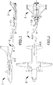
- Figures 1 and 2 show a side and an upper view respectively of an air to air active refuelling system (1) in a refuelling operation between a tanker aircraft (2) and a receiver aircraft (3).
- the air to air active refuelling system (1) comprises a hose (4) for driving fuel from a tanker aircraft (2) to a receiver aircraft (3) in a refuelling operation.
- Said hose (4) presents a drogue (5) located at a hose-end (4.1) suitable for being coupled with a probe (13) of the receiver aircraft (3).
- the hose (4) also comprises another end (4.2) opposite to the already mentioned hose-end (4.1) where the hose (4) is fixed to the tanker aircraft (2).
- the refuelling system (1) installed on the tanker aircraft (2) extends the hose (4) in order to couple the drogue (5) of the hose-end (4.1) to the probe (13) of the receiver aircraft (3) that is flying closer to the tanker aircraft (2) for allowing the approaching of the drogue (5) towards the probe (13).
- the fuel starts being driven through the hose (4) from the tanker aircraft (2) towards the receiver aircraft (3).
- the hose-end (4.1) comprises a drogue (5) and a coupling (8), the drogue (5) is arranged through the coupling (8) and is the component of the refuelling system (1) that is directly coupled to a probe (13) of a receiver aircraft (3) in refuelling operations (as in figures 1 and 2 ).
- the hose-end (4.1) also comprises a Hose Control Unit "HCU” (6) for providing aerodynamic radial loads at the end of the hose (4) in order to adapt the flight conditions of the refuelling system (1) in a refuelling operation.
- HCU Hose Control Unit
- the HCU (6) is located between the hose (4) and the coupling (8).
- Said HCU (6) shows three grid fins (7) in a deployed state. These grid fins (7) can be folded or deployed following the need of adapting the movement of the hose-end (4.1) in a refuelling operation.
- the grid fins (7) are deployed from the HCU (6) towards outside this HCU (6).
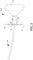
- Figures 4 and 5 show particular examples of an air to air active refuelling system (1). Particularly, figure 4 shows a perspective view of a hose-end (4.1) of the refuelling system (1) in detail and figure 5 shows a side view of another hose-end (4.1) in detail of a refuelling system (1).
- Both refuelling systems (1) of figure 4 and 5 comprise a HCU (6) located at the hose-end (4.1) and comprising a fix frame (6.1) and a rotary frame (6.2).
- the fix frame (6.1) is arranged along a longitudinal axis (X) around the hose (4) at the hose-end (4.1) and the rotatory frame (6.2) is rotationally connected to the fix frame (6.1).
- Said rotary frame (6.2) is configured to rotate around the same longitudinal axis (X) and provide adaptation to in-flight conditions.
- the HCU (6) shows four grid fins (7) located on the rotatory frame (6.2) and in a deployed state.
- Figure 5 shows a rotary frame (6.2) with three grid fins (7) in a deployed state and fin shafts (10) on which one grid fin (7) is respectively fixed on each fin shaft (10).
- the rotation of the rotatory frame (6.2) around the longitudinal axis (X) allows the free rotation of the plurality of grid fins (7) given that the grid fins (7) are fixed to the rotatory frame and their respective fin shafts (10) (according to figure 5 ) are also mounted on said rotatory frame (6.2).
- the contact will be understood as the time in which the drogue (5) of the tanker aircraft (2) comes in contact with the probe (13) of the receiver aircraft (3) (after the moment shown in figures 1 and 2 ). Therefore, during the contact in a refuelling operation the HCU (6) performs an active control of the axial forces transmitted between the receiver probe (13) and the coupling (8) by generating additional drag force.
- This additional drag force (aerodynamic radial loads) is provided by the actuation of a deflection angle ( ⁇ ) (shown in figure 6 ) in each grid fin (7) independently and the rotation of these grid fins (7).
- ⁇ deflection angle
- these aerodynamic radial loads at the hose-end (4.1) help to keep the force balance in contact between the tanker aircraft (2) and the receiver aircraft (3), in addition to drogue tension control and coupling latching forces, in a refuelling operation.
- Figure 6 shows a schematic view of an example of a rotatory frame (6.2) of an HCU (6), this view corresponding to a cross-sectional view to longitudinal axis (X) or the hose (4) of an air to air active refuelling system (1).
- a rotatory frame (6.2) of an HCU (6) it is shown four grid fins (7) in a deployed state and mounted on the rotatory frame (6.2) of the HCU (6).
- Each grid fin (7) is respectively mechanically connected to this rotatory frame (6.2) by a fin shaft (10).
- the fin shafts (10) are separated by 90° from each other respecting the longitudinal axis (X).
- the processing unit (11) is also able to provide folding/deploying actuation of said plurality of grid fins (7) by means of a folding mechanism (not shown in figures) located on the HCU (6).
- the deploying actuation is performed prior to configure the deflection angle ( ⁇ ) of each grid fin (7) and also prior to rotate these grid fins (7).
- the folding actuation is performed after the generation of aerodynamic radial loads by the actuation of the HCU (6).
Landscapes
- Engineering & Computer Science (AREA)
- Aviation & Aerospace Engineering (AREA)
- Rigid Pipes And Flexible Pipes (AREA)
- Loading And Unloading Of Fuel Tanks Or Ships (AREA)
- Tires In General (AREA)
- Arrangements For Transmission Of Measured Signals (AREA)
Priority Applications (4)
| Application Number | Priority Date | Filing Date | Title |
|---|---|---|---|
| ES20382943T ES2929595T3 (es) | 2020-10-29 | 2020-10-29 | Sistema de repostaje aire-aire activo y método para generar cargas radiales aerodinámicas en un extremo de manguera |
| EP20382943.7A EP3842345B1 (de) | 2020-10-29 | 2020-10-29 | System zur luft-zu-luft-betankung und verfahren zur erzeugung von aerodynamischen radialen lasten an einem schlauchende |
| US17/512,250 US11866191B2 (en) | 2020-10-29 | 2021-10-27 | Air to air active refueling system and method for generating aerodynamic radial loads at a hose-end |
| US18/129,699 US12415614B2 (en) | 2020-10-29 | 2023-03-31 | Air to air active refueling system and method for generating aerodynamic radial loads at a hose-end |
Applications Claiming Priority (1)
| Application Number | Priority Date | Filing Date | Title |
|---|---|---|---|
| EP20382943.7A EP3842345B1 (de) | 2020-10-29 | 2020-10-29 | System zur luft-zu-luft-betankung und verfahren zur erzeugung von aerodynamischen radialen lasten an einem schlauchende |
Publications (2)
| Publication Number | Publication Date |
|---|---|
| EP3842345A1 true EP3842345A1 (de) | 2021-06-30 |
| EP3842345B1 EP3842345B1 (de) | 2022-10-19 |
Family
ID=74504987
Family Applications (1)
| Application Number | Title | Priority Date | Filing Date |
|---|---|---|---|
| EP20382943.7A Active EP3842345B1 (de) | 2020-10-29 | 2020-10-29 | System zur luft-zu-luft-betankung und verfahren zur erzeugung von aerodynamischen radialen lasten an einem schlauchende |
Country Status (3)
| Country | Link |
|---|---|
| US (2) | US11866191B2 (de) |
| EP (1) | EP3842345B1 (de) |
| ES (1) | ES2929595T3 (de) |
Cited By (1)
| Publication number | Priority date | Publication date | Assignee | Title |
|---|---|---|---|---|
| CN114476122A (zh) * | 2022-03-21 | 2022-05-13 | 中国空气动力研究与发展中心高速空气动力研究所 | 一种基于风洞的空中加油仿真试验装置及方法 |
Families Citing this family (4)
| Publication number | Priority date | Publication date | Assignee | Title |
|---|---|---|---|---|
| CN114879718B (zh) * | 2022-07-12 | 2022-09-13 | 南京理工大学 | 具有栅格舵的飞行器的控制方法 |
| CN115196026A (zh) * | 2022-09-13 | 2022-10-18 | 中国航空工业集团公司沈阳空气动力研究所 | 一种用于软式加油管的位姿主动控制锥套及工作方法 |
| EP4385901B1 (de) * | 2022-12-15 | 2025-07-23 | Airbus Defence and Space, S.A.U. | Betankungssystem für flugzeuge |
| DE102024109732B4 (de) * | 2024-04-08 | 2026-04-02 | Deutsches Zentrum für Luft- und Raumfahrt e.V. | Rotorgesteuerte Koppeleinheit für die Luftbetankung |
Citations (4)
| Publication number | Priority date | Publication date | Assignee | Title |
|---|---|---|---|---|
| US20070084968A1 (en) * | 2004-07-23 | 2007-04-19 | The Boeing Company | In-flight refueling system, boom, and method for extending range of motion of an in-flight refueling boom |
| EP2266879A1 (de) * | 2009-06-04 | 2010-12-29 | SELEX Galileo S.p.A. | Luftbetankungssystem |
| US20130168497A1 (en) * | 2012-01-04 | 2013-07-04 | Israel Aerospace Industries Ltd. | Systems and methods for air vehicles |
| US20140306063A1 (en) * | 2013-04-11 | 2014-10-16 | The Boeing Company | Aerial refueling system and method |
Family Cites Families (15)
| Publication number | Priority date | Publication date | Assignee | Title |
|---|---|---|---|---|
| US4659036A (en) * | 1983-09-26 | 1987-04-21 | The Boeing Company | Missile control surface actuator system |
| DE3432468A1 (de) * | 1984-09-04 | 1986-03-13 | Messerschmitt Boelkow Blohm | Betankungseinrichtung fuer flugzeuge waehrend des fluges |
| US5642867A (en) * | 1995-06-06 | 1997-07-01 | Hughes Missile Systems Company | Aerodynamic lifting and control surface and control system using same |
| US7243879B2 (en) * | 2001-12-06 | 2007-07-17 | Kazak Composites, Incorporated | Lattice fin for missiles or other fluid-born bodies and method for producing same |
| US6994294B2 (en) * | 2003-08-29 | 2006-02-07 | Smiths Aerospace, Inc. | Stabilization of a drogue body |
| GB2418186B (en) * | 2003-08-29 | 2008-03-19 | Smiths Aerospace Inc | Stabilization of a drogue body |
| US7021586B2 (en) * | 2004-02-19 | 2006-04-04 | The Boeing Company | Force feedback refueling system for unmanned aircraft |
| WO2009091792A2 (en) * | 2008-01-15 | 2009-07-23 | Sysense, Inc. | A methodology for autonomous navigation and control of a tethered drogue |
| US8763955B1 (en) * | 2009-08-31 | 2014-07-01 | The Boeing Company | Method and apparatus for controlling a refueling drogue |
| US8561947B2 (en) * | 2011-01-05 | 2013-10-22 | Ge Aviation Systems, Llc | Method and system for a refueling drogue assembly |
| US10329016B1 (en) * | 2015-08-20 | 2019-06-25 | JAXON Enterprises, Inc. | Remote aerial manipulation platform |
| IL253015B2 (en) * | 2017-06-18 | 2023-07-01 | Israel Aerospace Ind Ltd | System and method for refueling aerial vehicles |
| CN108883826A (zh) * | 2017-08-31 | 2018-11-23 | 深圳市大疆创新科技有限公司 | 动力装置及单旋翼无人飞行器 |
| CN109631685B (zh) * | 2018-11-28 | 2021-06-29 | 湖北航天技术研究院总体设计所 | 一种栅格舵的折叠展开装置 |
| CN114152151B (zh) * | 2021-12-08 | 2023-08-04 | 航天科工火箭技术有限公司 | 一种折叠栅格舵 |
-
2020
- 2020-10-29 EP EP20382943.7A patent/EP3842345B1/de active Active
- 2020-10-29 ES ES20382943T patent/ES2929595T3/es active Active
-
2021
- 2021-10-27 US US17/512,250 patent/US11866191B2/en active Active
-
2023
- 2023-03-31 US US18/129,699 patent/US12415614B2/en active Active
Patent Citations (4)
| Publication number | Priority date | Publication date | Assignee | Title |
|---|---|---|---|---|
| US20070084968A1 (en) * | 2004-07-23 | 2007-04-19 | The Boeing Company | In-flight refueling system, boom, and method for extending range of motion of an in-flight refueling boom |
| EP2266879A1 (de) * | 2009-06-04 | 2010-12-29 | SELEX Galileo S.p.A. | Luftbetankungssystem |
| US20130168497A1 (en) * | 2012-01-04 | 2013-07-04 | Israel Aerospace Industries Ltd. | Systems and methods for air vehicles |
| US20140306063A1 (en) * | 2013-04-11 | 2014-10-16 | The Boeing Company | Aerial refueling system and method |
Cited By (2)
| Publication number | Priority date | Publication date | Assignee | Title |
|---|---|---|---|---|
| CN114476122A (zh) * | 2022-03-21 | 2022-05-13 | 中国空气动力研究与发展中心高速空气动力研究所 | 一种基于风洞的空中加油仿真试验装置及方法 |
| CN114476122B (zh) * | 2022-03-21 | 2023-08-29 | 中国空气动力研究与发展中心高速空气动力研究所 | 一种基于风洞的空中加油仿真试验装置及方法 |
Also Published As
| Publication number | Publication date |
|---|---|
| US11866191B2 (en) | 2024-01-09 |
| US12415614B2 (en) | 2025-09-16 |
| EP3842345B1 (de) | 2022-10-19 |
| US20230242270A1 (en) | 2023-08-03 |
| ES2929595T3 (es) | 2022-11-30 |
| US20220212810A1 (en) | 2022-07-07 |
Similar Documents
| Publication | Publication Date | Title |
|---|---|---|
| EP3842345B1 (de) | System zur luft-zu-luft-betankung und verfahren zur erzeugung von aerodynamischen radialen lasten an einem schlauchende | |
| US20220066471A1 (en) | Rotorcraft-assisted system and method for launching and retrieving a fixed-wing aircraft | |
| EP3645874B1 (de) | Verfahren zur reduzierung von schwingungen in windturbinenschaufeln | |
| JP5138671B2 (ja) | アダプタ、ツール、および取付機構を有する二部構成の宇宙飛行体整備ビークルシステム | |
| US11975821B2 (en) | Flight device | |
| JP4176718B2 (ja) | 空中給油用ホースを制御する装置および方法 | |
| EP2734446B1 (de) | Vorrichtung für ein luftbetankungssystem | |
| KR101477275B1 (ko) | 주 조종 장치 | |
| US11919655B2 (en) | System and method for refueling air vehicles | |
| US20170297738A1 (en) | Multicopter-assisted system and method for launching and retrieving a fixed-wing aircraft | |
| US8162261B2 (en) | Self contained power system for controllable refueling drogues | |
| GB2237251A (en) | In-flight refueling apparatus | |
| KR102227640B1 (ko) | 회전익 항공기 자동착륙 시스템 | |
| KR102253955B1 (ko) | 경로 유체 전달 장치 | |
| AU2023278083A1 (en) | Latching System And Method For VTOL Vehicles | |
| JP2007267485A (ja) | 無人ヘリコプタ及びこれに搭載される切断装置 | |
| US20050056730A1 (en) | Automatic pilot apparatus | |
| JP2007267484A (ja) | 無人ヘリコプタによるパイロットロープの延線方法 | |
| EP3680178B1 (de) | Luftbetankungsschlauchspannungssteuerung | |
| EP3040280A1 (de) | Verfahren und System zur Luftbetankung | |
| KR101885663B1 (ko) | 기계식 조종장치를 백업으로 갖는 전자식 비행제어 시스템 | |
| WO2025176755A1 (en) | Air to air refuelling system and method for powering devices of the system thereof |
Legal Events
| Date | Code | Title | Description |
|---|---|---|---|
| PUAI | Public reference made under article 153(3) epc to a published international application that has entered the european phase |
Free format text: ORIGINAL CODE: 0009012 |
|
| STAA | Information on the status of an ep patent application or granted ep patent |
Free format text: STATUS: THE APPLICATION HAS BEEN PUBLISHED |
|
| AK | Designated contracting states |
Kind code of ref document: A1 Designated state(s): AL AT BE BG CH CY CZ DE DK EE ES FI FR GB GR HR HU IE IS IT LI LT LU LV MC MK MT NL NO PL PT RO RS SE SI SK SM TR |
|
| STAA | Information on the status of an ep patent application or granted ep patent |
Free format text: STATUS: REQUEST FOR EXAMINATION WAS MADE |
|
| 17P | Request for examination filed |
Effective date: 20211116 |
|
| RBV | Designated contracting states (corrected) |
Designated state(s): AL AT BE BG CH CY CZ DE DK EE ES FI FR GB GR HR HU IE IS IT LI LT LU LV MC MK MT NL NO PL PT RO RS SE SI SK SM TR |
|
| GRAP | Despatch of communication of intention to grant a patent |
Free format text: ORIGINAL CODE: EPIDOSNIGR1 |
|
| STAA | Information on the status of an ep patent application or granted ep patent |
Free format text: STATUS: GRANT OF PATENT IS INTENDED |
|
| INTG | Intention to grant announced |
Effective date: 20220523 |
|
| GRAS | Grant fee paid |
Free format text: ORIGINAL CODE: EPIDOSNIGR3 |
|
| GRAA | (expected) grant |
Free format text: ORIGINAL CODE: 0009210 |
|
| STAA | Information on the status of an ep patent application or granted ep patent |
Free format text: STATUS: THE PATENT HAS BEEN GRANTED |
|
| AK | Designated contracting states |
Kind code of ref document: B1 Designated state(s): AL AT BE BG CH CY CZ DE DK EE ES FI FR GB GR HR HU IE IS IT LI LT LU LV MC MK MT NL NO PL PT RO RS SE SI SK SM TR |
|
| REG | Reference to a national code |
Ref country code: GB Ref legal event code: FG4D |
|
| REG | Reference to a national code |
Ref country code: CH Ref legal event code: EP |
|
| REG | Reference to a national code |
Ref country code: DE Ref legal event code: R096 Ref document number: 602020005746 Country of ref document: DE |
|
| REG | Reference to a national code |
Ref country code: IE Ref legal event code: FG4D |
|
| REG | Reference to a national code |
Ref country code: AT Ref legal event code: REF Ref document number: 1525416 Country of ref document: AT Kind code of ref document: T Effective date: 20221115 |
|
| REG | Reference to a national code |
Ref country code: ES Ref legal event code: FG2A Ref document number: 2929595 Country of ref document: ES Kind code of ref document: T3 Effective date: 20221130 |
|
| REG | Reference to a national code |
Ref country code: LT Ref legal event code: MG9D |
|
| REG | Reference to a national code |
Ref country code: NL Ref legal event code: MP Effective date: 20221019 |
|
| REG | Reference to a national code |
Ref country code: AT Ref legal event code: MK05 Ref document number: 1525416 Country of ref document: AT Kind code of ref document: T Effective date: 20221019 |
|
| PG25 | Lapsed in a contracting state [announced via postgrant information from national office to epo] |
Ref country code: NL Free format text: LAPSE BECAUSE OF FAILURE TO SUBMIT A TRANSLATION OF THE DESCRIPTION OR TO PAY THE FEE WITHIN THE PRESCRIBED TIME-LIMIT Effective date: 20221019 |
|
| PG25 | Lapsed in a contracting state [announced via postgrant information from national office to epo] |
Ref country code: SE Free format text: LAPSE BECAUSE OF FAILURE TO SUBMIT A TRANSLATION OF THE DESCRIPTION OR TO PAY THE FEE WITHIN THE PRESCRIBED TIME-LIMIT Effective date: 20221019 Ref country code: PT Free format text: LAPSE BECAUSE OF FAILURE TO SUBMIT A TRANSLATION OF THE DESCRIPTION OR TO PAY THE FEE WITHIN THE PRESCRIBED TIME-LIMIT Effective date: 20230220 Ref country code: NO Free format text: LAPSE BECAUSE OF FAILURE TO SUBMIT A TRANSLATION OF THE DESCRIPTION OR TO PAY THE FEE WITHIN THE PRESCRIBED TIME-LIMIT Effective date: 20230119 Ref country code: LT Free format text: LAPSE BECAUSE OF FAILURE TO SUBMIT A TRANSLATION OF THE DESCRIPTION OR TO PAY THE FEE WITHIN THE PRESCRIBED TIME-LIMIT Effective date: 20221019 Ref country code: FI Free format text: LAPSE BECAUSE OF FAILURE TO SUBMIT A TRANSLATION OF THE DESCRIPTION OR TO PAY THE FEE WITHIN THE PRESCRIBED TIME-LIMIT Effective date: 20221019 Ref country code: AT Free format text: LAPSE BECAUSE OF FAILURE TO SUBMIT A TRANSLATION OF THE DESCRIPTION OR TO PAY THE FEE WITHIN THE PRESCRIBED TIME-LIMIT Effective date: 20221019 |
|
| PG25 | Lapsed in a contracting state [announced via postgrant information from national office to epo] |
Ref country code: RS Free format text: LAPSE BECAUSE OF FAILURE TO SUBMIT A TRANSLATION OF THE DESCRIPTION OR TO PAY THE FEE WITHIN THE PRESCRIBED TIME-LIMIT Effective date: 20221019 Ref country code: PL Free format text: LAPSE BECAUSE OF FAILURE TO SUBMIT A TRANSLATION OF THE DESCRIPTION OR TO PAY THE FEE WITHIN THE PRESCRIBED TIME-LIMIT Effective date: 20221019 Ref country code: LV Free format text: LAPSE BECAUSE OF FAILURE TO SUBMIT A TRANSLATION OF THE DESCRIPTION OR TO PAY THE FEE WITHIN THE PRESCRIBED TIME-LIMIT Effective date: 20221019 Ref country code: IS Free format text: LAPSE BECAUSE OF FAILURE TO SUBMIT A TRANSLATION OF THE DESCRIPTION OR TO PAY THE FEE WITHIN THE PRESCRIBED TIME-LIMIT Effective date: 20230219 Ref country code: HR Free format text: LAPSE BECAUSE OF FAILURE TO SUBMIT A TRANSLATION OF THE DESCRIPTION OR TO PAY THE FEE WITHIN THE PRESCRIBED TIME-LIMIT Effective date: 20221019 Ref country code: GR Free format text: LAPSE BECAUSE OF FAILURE TO SUBMIT A TRANSLATION OF THE DESCRIPTION OR TO PAY THE FEE WITHIN THE PRESCRIBED TIME-LIMIT Effective date: 20230120 |
|
| REG | Reference to a national code |
Ref country code: BE Ref legal event code: MM Effective date: 20221031 |
|
| PG25 | Lapsed in a contracting state [announced via postgrant information from national office to epo] |
Ref country code: LU Free format text: LAPSE BECAUSE OF NON-PAYMENT OF DUE FEES Effective date: 20221029 |
|
| REG | Reference to a national code |
Ref country code: DE Ref legal event code: R097 Ref document number: 602020005746 Country of ref document: DE |
|
| PG25 | Lapsed in a contracting state [announced via postgrant information from national office to epo] |
Ref country code: SM Free format text: LAPSE BECAUSE OF FAILURE TO SUBMIT A TRANSLATION OF THE DESCRIPTION OR TO PAY THE FEE WITHIN THE PRESCRIBED TIME-LIMIT Effective date: 20221019 Ref country code: RO Free format text: LAPSE BECAUSE OF FAILURE TO SUBMIT A TRANSLATION OF THE DESCRIPTION OR TO PAY THE FEE WITHIN THE PRESCRIBED TIME-LIMIT Effective date: 20221019 Ref country code: MC Free format text: LAPSE BECAUSE OF FAILURE TO SUBMIT A TRANSLATION OF THE DESCRIPTION OR TO PAY THE FEE WITHIN THE PRESCRIBED TIME-LIMIT Effective date: 20221019 Ref country code: EE Free format text: LAPSE BECAUSE OF FAILURE TO SUBMIT A TRANSLATION OF THE DESCRIPTION OR TO PAY THE FEE WITHIN THE PRESCRIBED TIME-LIMIT Effective date: 20221019 Ref country code: DK Free format text: LAPSE BECAUSE OF FAILURE TO SUBMIT A TRANSLATION OF THE DESCRIPTION OR TO PAY THE FEE WITHIN THE PRESCRIBED TIME-LIMIT Effective date: 20221019 Ref country code: CZ Free format text: LAPSE BECAUSE OF FAILURE TO SUBMIT A TRANSLATION OF THE DESCRIPTION OR TO PAY THE FEE WITHIN THE PRESCRIBED TIME-LIMIT Effective date: 20221019 |
|
| PLBE | No opposition filed within time limit |
Free format text: ORIGINAL CODE: 0009261 |
|
| STAA | Information on the status of an ep patent application or granted ep patent |
Free format text: STATUS: NO OPPOSITION FILED WITHIN TIME LIMIT |
|
| PG25 | Lapsed in a contracting state [announced via postgrant information from national office to epo] |
Ref country code: SK Free format text: LAPSE BECAUSE OF FAILURE TO SUBMIT A TRANSLATION OF THE DESCRIPTION OR TO PAY THE FEE WITHIN THE PRESCRIBED TIME-LIMIT Effective date: 20221019 Ref country code: AL Free format text: LAPSE BECAUSE OF FAILURE TO SUBMIT A TRANSLATION OF THE DESCRIPTION OR TO PAY THE FEE WITHIN THE PRESCRIBED TIME-LIMIT Effective date: 20221019 |
|
| 26N | No opposition filed |
Effective date: 20230720 |
|
| PG25 | Lapsed in a contracting state [announced via postgrant information from national office to epo] |
Ref country code: BE Free format text: LAPSE BECAUSE OF NON-PAYMENT OF DUE FEES Effective date: 20221031 |
|
| PG25 | Lapsed in a contracting state [announced via postgrant information from national office to epo] |
Ref country code: IE Free format text: LAPSE BECAUSE OF NON-PAYMENT OF DUE FEES Effective date: 20221029 |
|
| PG25 | Lapsed in a contracting state [announced via postgrant information from national office to epo] |
Ref country code: SI Free format text: LAPSE BECAUSE OF FAILURE TO SUBMIT A TRANSLATION OF THE DESCRIPTION OR TO PAY THE FEE WITHIN THE PRESCRIBED TIME-LIMIT Effective date: 20221019 |
|
| PG25 | Lapsed in a contracting state [announced via postgrant information from national office to epo] |
Ref country code: CY Free format text: LAPSE BECAUSE OF FAILURE TO SUBMIT A TRANSLATION OF THE DESCRIPTION OR TO PAY THE FEE WITHIN THE PRESCRIBED TIME-LIMIT Effective date: 20221019 |
|
| PG25 | Lapsed in a contracting state [announced via postgrant information from national office to epo] |
Ref country code: MK Free format text: LAPSE BECAUSE OF FAILURE TO SUBMIT A TRANSLATION OF THE DESCRIPTION OR TO PAY THE FEE WITHIN THE PRESCRIBED TIME-LIMIT Effective date: 20221019 Ref country code: IT Free format text: LAPSE BECAUSE OF FAILURE TO SUBMIT A TRANSLATION OF THE DESCRIPTION OR TO PAY THE FEE WITHIN THE PRESCRIBED TIME-LIMIT Effective date: 20221019 |
|
| REG | Reference to a national code |
Ref country code: CH Ref legal event code: PL |
|
| PG25 | Lapsed in a contracting state [announced via postgrant information from national office to epo] |
Ref country code: CH Free format text: LAPSE BECAUSE OF NON-PAYMENT OF DUE FEES Effective date: 20231031 |
|
| PG25 | Lapsed in a contracting state [announced via postgrant information from national office to epo] |
Ref country code: HU Free format text: LAPSE BECAUSE OF FAILURE TO SUBMIT A TRANSLATION OF THE DESCRIPTION OR TO PAY THE FEE WITHIN THE PRESCRIBED TIME-LIMIT; INVALID AB INITIO Effective date: 20201029 Ref country code: CH Free format text: LAPSE BECAUSE OF NON-PAYMENT OF DUE FEES Effective date: 20231031 Ref country code: BG Free format text: LAPSE BECAUSE OF FAILURE TO SUBMIT A TRANSLATION OF THE DESCRIPTION OR TO PAY THE FEE WITHIN THE PRESCRIBED TIME-LIMIT Effective date: 20221019 |
|
| PG25 | Lapsed in a contracting state [announced via postgrant information from national office to epo] |
Ref country code: MT Free format text: LAPSE BECAUSE OF FAILURE TO SUBMIT A TRANSLATION OF THE DESCRIPTION OR TO PAY THE FEE WITHIN THE PRESCRIBED TIME-LIMIT Effective date: 20221019 |
|
| PG25 | Lapsed in a contracting state [announced via postgrant information from national office to epo] |
Ref country code: TR Free format text: LAPSE BECAUSE OF FAILURE TO SUBMIT A TRANSLATION OF THE DESCRIPTION OR TO PAY THE FEE WITHIN THE PRESCRIBED TIME-LIMIT Effective date: 20221019 |
|
| PGFP | Annual fee paid to national office [announced via postgrant information from national office to epo] |
Ref country code: DE Payment date: 20251021 Year of fee payment: 6 |
|
| PGFP | Annual fee paid to national office [announced via postgrant information from national office to epo] |
Ref country code: GB Payment date: 20251022 Year of fee payment: 6 |
|
| PGFP | Annual fee paid to national office [announced via postgrant information from national office to epo] |
Ref country code: FR Payment date: 20251030 Year of fee payment: 6 |
|
| PGFP | Annual fee paid to national office [announced via postgrant information from national office to epo] |
Ref country code: ES Payment date: 20251216 Year of fee payment: 6 |