EP3842650A1 - Walzlagervorverdichtungsverfahren, lagervorverdichtungsvorrichtung, lageranordnung, maschine und fahrzeug - Google Patents
Walzlagervorverdichtungsverfahren, lagervorverdichtungsvorrichtung, lageranordnung, maschine und fahrzeug Download PDFInfo
- Publication number
- EP3842650A1 EP3842650A1 EP19851181.8A EP19851181A EP3842650A1 EP 3842650 A1 EP3842650 A1 EP 3842650A1 EP 19851181 A EP19851181 A EP 19851181A EP 3842650 A1 EP3842650 A1 EP 3842650A1
- Authority
- EP
- European Patent Office
- Prior art keywords
- bearing
- rolling bearing
- peripheral surface
- wedge
- rotating shaft
- Prior art date
- Legal status (The legal status is an assumption and is not a legal conclusion. Google has not performed a legal analysis and makes no representation as to the accuracy of the status listed.)
- Granted
Links
Images




Classifications
-
- F—MECHANICAL ENGINEERING; LIGHTING; HEATING; WEAPONS; BLASTING
- F16—ENGINEERING ELEMENTS AND UNITS; GENERAL MEASURES FOR PRODUCING AND MAINTAINING EFFECTIVE FUNCTIONING OF MACHINES OR INSTALLATIONS; THERMAL INSULATION IN GENERAL
- F16C—SHAFTS; FLEXIBLE SHAFTS; ELEMENTS OR CRANKSHAFT MECHANISMS; ROTARY BODIES OTHER THAN GEARING ELEMENTS; BEARINGS
- F16C25/00—Bearings for exclusively rotary movement adjustable for wear or play
- F16C25/06—Ball or roller bearings
-
- B—PERFORMING OPERATIONS; TRANSPORTING
- B23—MACHINE TOOLS; METAL-WORKING NOT OTHERWISE PROVIDED FOR
- B23P—METAL-WORKING NOT OTHERWISE PROVIDED FOR; COMBINED OPERATIONS; UNIVERSAL MACHINE TOOLS
- B23P21/00—Machines for assembling a multiplicity of different parts to compose units, with or without preceding or subsequent working of such parts, e.g. with program control
-
- F—MECHANICAL ENGINEERING; LIGHTING; HEATING; WEAPONS; BLASTING
- F16—ENGINEERING ELEMENTS AND UNITS; GENERAL MEASURES FOR PRODUCING AND MAINTAINING EFFECTIVE FUNCTIONING OF MACHINES OR INSTALLATIONS; THERMAL INSULATION IN GENERAL
- F16C—SHAFTS; FLEXIBLE SHAFTS; ELEMENTS OR CRANKSHAFT MECHANISMS; ROTARY BODIES OTHER THAN GEARING ELEMENTS; BEARINGS
- F16C19/00—Bearings with rolling contact, for exclusively rotary movement
- F16C19/54—Systems consisting of a plurality of bearings with rolling friction
-
- F—MECHANICAL ENGINEERING; LIGHTING; HEATING; WEAPONS; BLASTING
- F16—ENGINEERING ELEMENTS AND UNITS; GENERAL MEASURES FOR PRODUCING AND MAINTAINING EFFECTIVE FUNCTIONING OF MACHINES OR INSTALLATIONS; THERMAL INSULATION IN GENERAL
- F16C—SHAFTS; FLEXIBLE SHAFTS; ELEMENTS OR CRANKSHAFT MECHANISMS; ROTARY BODIES OTHER THAN GEARING ELEMENTS; BEARINGS
- F16C19/00—Bearings with rolling contact, for exclusively rotary movement
- F16C19/54—Systems consisting of a plurality of bearings with rolling friction
- F16C19/546—Systems with spaced apart rolling bearings including at least one angular contact bearing
- F16C19/547—Systems with spaced apart rolling bearings including at least one angular contact bearing with two angular contact rolling bearings
- F16C19/548—Systems with spaced apart rolling bearings including at least one angular contact bearing with two angular contact rolling bearings in O-arrangement
-
- F—MECHANICAL ENGINEERING; LIGHTING; HEATING; WEAPONS; BLASTING
- F16—ENGINEERING ELEMENTS AND UNITS; GENERAL MEASURES FOR PRODUCING AND MAINTAINING EFFECTIVE FUNCTIONING OF MACHINES OR INSTALLATIONS; THERMAL INSULATION IN GENERAL
- F16C—SHAFTS; FLEXIBLE SHAFTS; ELEMENTS OR CRANKSHAFT MECHANISMS; ROTARY BODIES OTHER THAN GEARING ELEMENTS; BEARINGS
- F16C25/00—Bearings for exclusively rotary movement adjustable for wear or play
- F16C25/06—Ball or roller bearings
- F16C25/08—Ball or roller bearings self-adjusting
-
- F—MECHANICAL ENGINEERING; LIGHTING; HEATING; WEAPONS; BLASTING
- F16—ENGINEERING ELEMENTS AND UNITS; GENERAL MEASURES FOR PRODUCING AND MAINTAINING EFFECTIVE FUNCTIONING OF MACHINES OR INSTALLATIONS; THERMAL INSULATION IN GENERAL
- F16C—SHAFTS; FLEXIBLE SHAFTS; ELEMENTS OR CRANKSHAFT MECHANISMS; ROTARY BODIES OTHER THAN GEARING ELEMENTS; BEARINGS
- F16C35/00—Rigid support of bearing units; Housings, e.g. caps, covers
- F16C35/04—Rigid support of bearing units; Housings, e.g. caps, covers in the case of ball or roller bearings
- F16C35/06—Mounting or dismounting of ball or roller bearings; Fixing them onto shaft or in housing
- F16C35/07—Fixing them on the shaft or housing with interposition of an element
- F16C35/073—Fixing them on the shaft or housing with interposition of an element between shaft and inner race ring
-
- F—MECHANICAL ENGINEERING; LIGHTING; HEATING; WEAPONS; BLASTING
- F16—ENGINEERING ELEMENTS AND UNITS; GENERAL MEASURES FOR PRODUCING AND MAINTAINING EFFECTIVE FUNCTIONING OF MACHINES OR INSTALLATIONS; THERMAL INSULATION IN GENERAL
- F16C—SHAFTS; FLEXIBLE SHAFTS; ELEMENTS OR CRANKSHAFT MECHANISMS; ROTARY BODIES OTHER THAN GEARING ELEMENTS; BEARINGS
- F16C35/00—Rigid support of bearing units; Housings, e.g. caps, covers
- F16C35/04—Rigid support of bearing units; Housings, e.g. caps, covers in the case of ball or roller bearings
- F16C35/06—Mounting or dismounting of ball or roller bearings; Fixing them onto shaft or in housing
- F16C35/07—Fixing them on the shaft or housing with interposition of an element
- F16C35/077—Fixing them on the shaft or housing with interposition of an element between housing and outer race ring
-
- F—MECHANICAL ENGINEERING; LIGHTING; HEATING; WEAPONS; BLASTING
- F16—ENGINEERING ELEMENTS AND UNITS; GENERAL MEASURES FOR PRODUCING AND MAINTAINING EFFECTIVE FUNCTIONING OF MACHINES OR INSTALLATIONS; THERMAL INSULATION IN GENERAL
- F16C—SHAFTS; FLEXIBLE SHAFTS; ELEMENTS OR CRANKSHAFT MECHANISMS; ROTARY BODIES OTHER THAN GEARING ELEMENTS; BEARINGS
- F16C43/00—Assembling bearings
- F16C43/04—Assembling rolling-contact bearings
-
- F—MECHANICAL ENGINEERING; LIGHTING; HEATING; WEAPONS; BLASTING
- F16—ENGINEERING ELEMENTS AND UNITS; GENERAL MEASURES FOR PRODUCING AND MAINTAINING EFFECTIVE FUNCTIONING OF MACHINES OR INSTALLATIONS; THERMAL INSULATION IN GENERAL
- F16C—SHAFTS; FLEXIBLE SHAFTS; ELEMENTS OR CRANKSHAFT MECHANISMS; ROTARY BODIES OTHER THAN GEARING ELEMENTS; BEARINGS
- F16C19/00—Bearings with rolling contact, for exclusively rotary movement
- F16C19/02—Bearings with rolling contact, for exclusively rotary movement with bearing balls essentially of the same size in one or more circular rows
- F16C19/14—Bearings with rolling contact, for exclusively rotary movement with bearing balls essentially of the same size in one or more circular rows for both radial and axial load
- F16C19/16—Bearings with rolling contact, for exclusively rotary movement with bearing balls essentially of the same size in one or more circular rows for both radial and axial load with a single row of balls
- F16C19/163—Bearings with rolling contact, for exclusively rotary movement with bearing balls essentially of the same size in one or more circular rows for both radial and axial load with a single row of balls with angular contact
-
- F—MECHANICAL ENGINEERING; LIGHTING; HEATING; WEAPONS; BLASTING
- F16—ENGINEERING ELEMENTS AND UNITS; GENERAL MEASURES FOR PRODUCING AND MAINTAINING EFFECTIVE FUNCTIONING OF MACHINES OR INSTALLATIONS; THERMAL INSULATION IN GENERAL
- F16C—SHAFTS; FLEXIBLE SHAFTS; ELEMENTS OR CRANKSHAFT MECHANISMS; ROTARY BODIES OTHER THAN GEARING ELEMENTS; BEARINGS
- F16C19/00—Bearings with rolling contact, for exclusively rotary movement
- F16C19/02—Bearings with rolling contact, for exclusively rotary movement with bearing balls essentially of the same size in one or more circular rows
- F16C19/14—Bearings with rolling contact, for exclusively rotary movement with bearing balls essentially of the same size in one or more circular rows for both radial and axial load
- F16C19/18—Bearings with rolling contact, for exclusively rotary movement with bearing balls essentially of the same size in one or more circular rows for both radial and axial load with two or more rows of balls
- F16C19/181—Bearings with rolling contact, for exclusively rotary movement with bearing balls essentially of the same size in one or more circular rows for both radial and axial load with two or more rows of balls with angular contact
- F16C19/182—Bearings with rolling contact, for exclusively rotary movement with bearing balls essentially of the same size in one or more circular rows for both radial and axial load with two or more rows of balls with angular contact in tandem arrangement
-
- F—MECHANICAL ENGINEERING; LIGHTING; HEATING; WEAPONS; BLASTING
- F16—ENGINEERING ELEMENTS AND UNITS; GENERAL MEASURES FOR PRODUCING AND MAINTAINING EFFECTIVE FUNCTIONING OF MACHINES OR INSTALLATIONS; THERMAL INSULATION IN GENERAL
- F16C—SHAFTS; FLEXIBLE SHAFTS; ELEMENTS OR CRANKSHAFT MECHANISMS; ROTARY BODIES OTHER THAN GEARING ELEMENTS; BEARINGS
- F16C2226/00—Joining parts; Fastening; Assembling or mounting parts
- F16C2226/10—Force connections, e.g. clamping
- F16C2226/16—Force connections, e.g. clamping by wedge action, e.g. by tapered or conical parts
-
- F—MECHANICAL ENGINEERING; LIGHTING; HEATING; WEAPONS; BLASTING
- F16—ENGINEERING ELEMENTS AND UNITS; GENERAL MEASURES FOR PRODUCING AND MAINTAINING EFFECTIVE FUNCTIONING OF MACHINES OR INSTALLATIONS; THERMAL INSULATION IN GENERAL
- F16C—SHAFTS; FLEXIBLE SHAFTS; ELEMENTS OR CRANKSHAFT MECHANISMS; ROTARY BODIES OTHER THAN GEARING ELEMENTS; BEARINGS
- F16C2226/00—Joining parts; Fastening; Assembling or mounting parts
- F16C2226/50—Positive connections
- F16C2226/60—Positive connections with threaded parts, e.g. bolt and nut connections
-
- F—MECHANICAL ENGINEERING; LIGHTING; HEATING; WEAPONS; BLASTING
- F16—ENGINEERING ELEMENTS AND UNITS; GENERAL MEASURES FOR PRODUCING AND MAINTAINING EFFECTIVE FUNCTIONING OF MACHINES OR INSTALLATIONS; THERMAL INSULATION IN GENERAL
- F16C—SHAFTS; FLEXIBLE SHAFTS; ELEMENTS OR CRANKSHAFT MECHANISMS; ROTARY BODIES OTHER THAN GEARING ELEMENTS; BEARINGS
- F16C2226/00—Joining parts; Fastening; Assembling or mounting parts
- F16C2226/50—Positive connections
- F16C2226/62—Positive connections with pins, bolts or dowels
-
- F—MECHANICAL ENGINEERING; LIGHTING; HEATING; WEAPONS; BLASTING
- F16—ENGINEERING ELEMENTS AND UNITS; GENERAL MEASURES FOR PRODUCING AND MAINTAINING EFFECTIVE FUNCTIONING OF MACHINES OR INSTALLATIONS; THERMAL INSULATION IN GENERAL
- F16C—SHAFTS; FLEXIBLE SHAFTS; ELEMENTS OR CRANKSHAFT MECHANISMS; ROTARY BODIES OTHER THAN GEARING ELEMENTS; BEARINGS
- F16C2326/00—Articles relating to transporting
- F16C2326/01—Parts of vehicles in general
-
- F—MECHANICAL ENGINEERING; LIGHTING; HEATING; WEAPONS; BLASTING
- F16—ENGINEERING ELEMENTS AND UNITS; GENERAL MEASURES FOR PRODUCING AND MAINTAINING EFFECTIVE FUNCTIONING OF MACHINES OR INSTALLATIONS; THERMAL INSULATION IN GENERAL
- F16C—SHAFTS; FLEXIBLE SHAFTS; ELEMENTS OR CRANKSHAFT MECHANISMS; ROTARY BODIES OTHER THAN GEARING ELEMENTS; BEARINGS
- F16C35/00—Rigid support of bearing units; Housings, e.g. caps, covers
- F16C35/04—Rigid support of bearing units; Housings, e.g. caps, covers in the case of ball or roller bearings
- F16C35/06—Mounting or dismounting of ball or roller bearings; Fixing them onto shaft or in housing
- F16C35/061—Mounting or dismounting of ball or roller bearings; Fixing them onto shaft or in housing mounting a plurality of bearings side by side
Definitions
- the present invention relates to a rolling bearing preloading method, a bearing preload device, a bearing assembly, a machine equipped with the bearing assembly, and a vehicle.
- a rotating shaft 101 may be supported by a housing 103 via a pair of rolling bearings 105 separated in an axial direction.
- a preload is applied to the rolling bearing 105 to exert the required rigidity.
- preload application constant pressure preloading which applies a preload to the rolling bearing 105 by a spring 107 as illustrated in Fig. 6
- a fixed position preloading which applies a preload load by giving a dimensional difference between inner rings 113 and outer rings 115 of the rolling bearings 105 by spacers 109 and 111 as illustrated in Fig. 7 .
- the fixed position preloading is more likely to obtain higher rigidity than the constant pressure preloading.
- the amount of preload can be changed by the influence of a dimensional change of the rotating shaft 101 and the housing 103 due to thermal expansion, and thus there is a concern that problems such as excessive preload and loss of preload may occur under harsh operating conditions.
- Patent Literature 1 uses a spacer having a special structure which includes two inner ring spacers and a preload adjusting ring provided between the inner ring spacers. Therefore, the number of parts increases and the structure of rolling bearings becomes complicated due to the use of special parts. As a result, there are problems such as an increase in the manufacturing cost of the rolling bearing and a decrease in maintainability.
- Patent Literature 2 and Patent Literature 3 use a complicated hydraulic mechanism, there is a problem that the mechanism of the rolling bearing becomes large and the structure becomes complicated.
- a method of preventing a relative movement of the inner ring and shaft of a rolling bearing and the outer ring and housing by a method other than press fitting there is a method of using the preload itself as illustrated in Fig. 8 .
- Such method is often used when used at a relatively light load and low speed rotation.
- a fixed position preload spacer 117 on the inner ring 113 side whose axial dimension is adjusted to be shorter by the preload with respect to an axial distance between the pair of outer rings 115 determined by the housing 103 is prepared, the fixed position preload spacer 117 is interposed between the pair of inner rings 113, and then the inner ring 113 is tightened by a bearing nut 119.
- Such method has a simple mechanism, but especially in the outer ring 115, the fixing strength against backlash in a radial direction (diameter direction) is weak.
- the fixing effect of the outer ring 115 is lost, which causes the accuracy of the rolling bearing to deviate and creep to occur.
- the inner ring 113 since the position is held by the friction caused by an axial force, the inner ring 113 may move (shift) in the radial direction by the amount of the gap between the rotating shaft 101 and the inner ring 113 due to an impact load or the like.
- Patent Literatures 4 and 5 have a configuration in which a desired preload or radial force is applied or not applied at all by inserting a wedge member and the adjustment function to increase or decrease the preload is not obtained.
- An object of the invention is to provide a rolling bearing preloading method, a bearing preload device, a bearing assembly, a machine equipped with the bearing assembly, and a vehicle, which can apply an appropriate fixed position preload without increasing the size of a bearing mechanism and impairing maintainability.
- the invention has the following configuration.
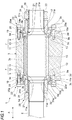
- Fig. 1 is a cross-sectional view of a bearing assembly according to a first embodiment of the invention and Fig. 2 is a partially enlarged view of Fig. 1. Figs. 1 and 2 also illustrate a preloading method according to an embodiment of the invention.
- a bearing assembly 1 includes a housing 3, a rotating shaft 5, and a pair of rolling bearings 7 (hereinafter, simply referred to as "bearings").
- the housing 3 supports the rotating shaft 5 via the pair of bearings 7 provided apart in an axial direction (direction indicated by an arrow A).
- Each bearing 7 includes an outer ring 9 fixed to the housing 3, an inner ring 11 fixed to the rotating shaft 5, and a plurality of rolling elements 13 arranged between the outer ring 9 and the inner ring 11 and rolling.
- a shaft hole 3a is formed in the housing 3 along the axial direction and notches 3b into which the outer rings 9 of the bearings 7 are fitted are provided at both ends of the shaft hole 3a in the axial direction.
- An axial distance between the pair of outer rings 9 is kept equal to an axial distance between the pair of notches 3b.
- a spacer 15 whose size is selected (or formed) shorter than the distance between the steps of the notches 3b by the preload is provided.
- the spacer 15 is a tubular member of which the rotating shaft 5 is inserted into an inner peripheral portion.
- male screw portions 5a and 5b are formed in the vicinities of the axial positions where both ends of the housing 3 are arranged.
- Preload nuts 17 are respectively attached to the male screw portions 5a and 5b.
- Respective inner rings 11 are tightened from both sides in the axial direction by the preload nuts 17 in a state where the spacer 15 is interposed therebetween. As a result, the required preload is applied to each bearing 7.
- Each of the pair of outer rings 9 is provided with an outer wedge member 19 between an outer peripheral surface 9a and the housing 3.
- the outer wedge member 19 is inserted along an inclined inner peripheral surface 3c formed in a region of the housing 3 facing the outer peripheral surface 9a of the outer ring 9.
- the outer wedge member 19 is an annular member having an inclined surface 19a whose radial thickness gradually increases from the tip end portion in an insertion direction toward a base end portion.
- the inclined surface 19a and the inclined inner peripheral surface 3c of the housing 3 are in contact with each other and a surface 19b opposite from the inclined surface 19a and the outer ring 9 are in contact with each other.
- Inner wedge members 21 are respectively provided between the inner peripheral surfaces 11a of the pair of inner rings 11 and the rotating shaft 5.
- the inner wedge member 21 is inserted along an inclined outer peripheral surface 5c formed in a region of the rotating shaft 5 facing the inner peripheral surface 11a of the inner ring 11.
- the inner wedge member 21 is an annular member having an inclined surface 21a whose radial thickness gradually increases from the tip end portion in the insertion direction toward the base end portion.
- the inclined surface 21a and the inclined outer peripheral surface 5c are in contact with each other.
- the pair of outer wedge members 19 are respectively tightened in the insertion direction by first tightening mechanisms 23 and are fixed between the outer ring 9 and the housing 3.
- the pair of inner wedge members 21 are respectively tightened in the insertion direction by second tightening mechanisms 29 and are fixed between the inner ring 11 and the rotating shaft 5.
- the first tightening mechanism 23 and the second tightening mechanism 29 form a bearing preload device which uses the bearing preloading method according to the embodiment of the invention.
- the first tightening mechanism 23 includes a first pushing member 25 which is in contact with the base end of the outer wedge member 19 and a plurality of bolts (tightening members) 27 which tighten the first pushing member 25 in the insertion direction of the outer wedge member 19.
- the first pushing member 25 is an annular member and is provided on the outer diameter side of a preload nut 17.
- the first pushing member 25 is provided with bolt insertion holes 25a through which the bolts 27 are inserted at a plurality of locations along a circumferential direction. Screw holes 3d into which bolts 27 are screwed are provided at a plurality of locations along the circumferential direction in parts of the housing 3 facing the first pushing members 25 at both ends in the axial direction.
- the first pushing member 25 is fixed to the housing 3 by inserting the bolt 27 into the screw hole 3d through each bolt insertion hole 25a and tightening the bolt 27.
- the outer wedge member 19 is pressed by the first pushing member 25 and inserted between the outer ring 9 and the housing 3.
- the second tightening mechanism 29 includes a second pushing member 31 which is in contact with the base end of the inner wedge member 21 and a nut (tightening member) 33 which tightens the second pushing member 31 toward the insertion direction of the inner wedge member 21.
- the second pushing member 31 is integrally formed of an annular portion 31a in contact with the base end of the inner wedge member 21 and a pressing portion 31b extending rearward from the annular portion 31a in the insertion direction of the inner wedge member 21.
- the nut 33 illustrated in Fig. 2 is attached to the male screw portion 5b.
- the nut 33 is attached to the male screw portion 5a illustrated in Fig. 1 .
- the inner wedge member 21 is pressed against the second pushing member 31 by tightening the nut 33 and is inserted between the inner ring 11 and the rotating shaft 5.
- the wedge effect of the outer wedge member 19 and the inner wedge member 21 allows the outer ring 9 and the inner ring 11 of the bearing 7 to be directly and firmly fixed to the housing 3 and the rotating shaft 5 in addition to the configuration in which the normal fixed position preloading is performed. Therefore, even when the rotating shaft 5 receives a large input, the bearing 7 is less likely to be displaced.
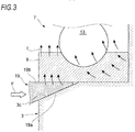
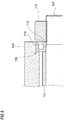
- Fig. 3 illustrates the wedge effect of the outer wedge member 19 inserted between the outer ring 9 and the housing 3.
- An arrow F in the drawing illustrates a pushing force applied to the outer wedge member 19 and an arrow f schematically illustrates a direction of stress in each part of the outer wedge member 19.
- the outer wedge member 19 and the inner wedge member 21 can apply an appropriate preload to the bearing 7 to add rigidity by appropriately designing the position of action of the force due to the wedge effect on the bearing 7 as illustrated in Fig. 3 , as similar to the fixed position preloading which applies the preload by the dimensional difference between the inner and outer spacers.
- a small preload to the extent that determines the position of the rotating shaft 5 in a free state is applied by a normal fixed position preloading and a stronger preload for ensuring rigidity is applied by tightening by the wedge effect, in such a manner that it is possible to prevent changes in preload and occurrence of disconnection due to dimensional changes in the rotating shaft 5 and the housing 3 due to temperature changes.
- the outer ring 9 and the inner ring 11 of the bearing 7 illustrated in Figs. 1 and 2 can be firmly fixed in the axial direction by the friction generated by the tightening force due to the wedge effect. That is, compared with the normal fixed position preload bearing assembly in which the inner ring 11 and the outer ring 9 are fixed to the rotating shaft 5 and the housing 3, fixing is possible with an extremely small tightening force by the first tightening mechanism 23 and the second tightening mechanism 29.
- This can make the bolt 27, which is a tightening member for the outer ring 9, small size and reduce the number of the bolt 27, ensuring high rigidity in a smaller space compared to a normal bearing assembly with the fixed position preload.
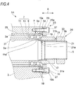
- Fig. 4 is a cross-sectional view of a bearing assembly 1A according to a second embodiment of the invention.
- components which are the same as or functionally common to the components described above will be designated by the same reference numerals and letters, and the description thereof will be omitted as appropriate.
- the bearings 7 are arranged in multiple rows (two rows in the example) at both ends of the housing 3 in the axial direction.
- An outer ring spacer 35 and an inner ring spacer 37 are provided between the pair of bearings 7 arranged inside in the axial direction.
- the outer ring spacer 35 is provided between the outer rings 9 of the pair of inner bearings 7 and the inner ring spacer 37 is provided between the inner rings 11 of the pair of inner bearings 7.
- the axial dimension of the inner ring spacer 37 is selected (formed) shorter than the axial dimension of the outer ring spacer 35 by the preload.
- the inner rings 11 of the pair of inner bearings 7 are fastened from both sides in the axial direction in a state where the inner ring spacer 37 is interposed therebetween by the preload nuts 17 together with the inner rings 11 of the pair of outer bearings 7. Therefore, each bearing 7 is applied the required preload.
- the wedge effect of the outer wedge member 19 and the inner wedge member 21 can directly and firmly fix the outer ring 9 and the inner ring 11 of the bearing 7 to the housing 3 and the rotating shaft 5.
- Fixing by the wedge effect is highly effective in preventing displacement in a radial direction. Therefore, by applying the fixing by the wedge effect to a part or all of the bearings 7 used in the double row, it is possible to realize the bearing assembly 1A which is easy to disassemble and maintain and has high accuracy.
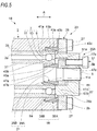
- Fig. 5 is a cross-sectional view of the bearing assembly 1B according to a third embodiment of the invention.
- the outer wedge member 19 of the bearing assembly 1B illustrated in Fig. 5 includes a pair of annular wedge pieces 38A and 38B and the inner wedge member 21 has a pair of annular wedge pieces 39A and 39B.
- the pair of wedge pieces 38A and 38B respectively have inclined engaging surfaces 41a and 43a and the pair of wedge pieces 39A and 39B respectively have inclined engaging surfaces 45a and 47a.
- One wedge piece 38B of the outer wedge member 19 is fitted onto the outer peripheral surface 9a of the outer ring 9 of the bearing 7 and the other wedge piece 38A is inserted into the notch 3b formed in the housing 3, which is a mating member facing the outer ring 9 of the bearing 7.
- One wedge piece 39A of the inner wedge member 21 is fitted in the inner peripheral surface 11a of the inner ring 11 of the bearing 7 and the other wedge piece 39B is inserted along the outer peripheral surface of the rotating shaft 5, which is a mating member facing the inner ring 11 of the bearing 7.
- the second tightening mechanism 29A includes a second pushing member 41 which is in contact with a side surface 47c of the wedge piece 39B of the inner wedge member 21 and a bolt (tightening member) 51 which tightens the second pushing member 41 toward the insertion direction of the inner wedge member 21.
- the second pushing member 41 is an annular member movably mounted on the rotating shaft 5 in the axial direction and is provided in an internal space of the preload nut 17 in the example.
- the preload nut 17 includes a disc-shaped base portion 17A screwed into the male screw portion 5b of the rotating shaft 5 and an abutment portion 17B erected from an outer peripheral portion of the base portion 17A.
- the abutment portion 17B is inserted into an opening 25b of the first pushing member 25 and fix the inner ring 11 of the bearing 7 in the axial direction by a part of the tip end side of the abutment portion 17B.
- the bolt 51 is attached to a bolt hole 17a which axially penetrates the preload nut 17 and a bolt tip 51a abuts on the second pushing member 41. Then, when the bolt 51 is tightened, the second pushing member 41 presses the inner wedge piece 39B in the axial direction, and thus a radial force due to the wedge effect is generated between the inclined engaging surface 47a of the wedge piece 39B and the inclined engaging surface 45a of the wedge piece 39A. As a result, the inner ring 11 of the bearing 7 can be directly and firmly fixed to the rotating shaft 5.
- each bolt 51 causes the second pushing member 41 to evenly press the wedge piece 39B.
- each of the outer wedge member 19 and the inner wedge member 21 exerts the wedge effect. Therefore, it is not necessary to provide the inclined inner peripheral surface 3c (see Figs. 1 and 2 ) in the housing 3 and it is not necessary to provide the inclined outer peripheral surface 5c (see Figs. 1 and 2 ) in the rotating shaft 5. Therefore, it is not necessary to separately process the housing 3 and the rotating shaft 5 to obtain the wedge effect, so that a bearing assembly 1B can be realized at a relatively low cost.
- the outer wedge member 19 is provided between the outer ring 9 and the housing 3 and the inner wedge member 21 is provided between the inner ring 11 and the rotating shaft 5, in such a manner that the outer ring 9 and the inner ring 11 are respectively fixed to the housing 3 and the rotating shaft 5 by the wedge effect.
- only one of the outer wedge member 19 and the inner wedge member 21 described above may be provided.
- the invention is not limited to the embodiment described above. It is also planned to combine the configurations of the embodiments with each other, to be modified and applied by those skilled in the art based on the description of the specification and well-known techniques, and those are included in the scope of seeking protection.
- the bearing preloading method described above can also be applied to various machines (including machines in which the power of an instrument or the like is manual) equipped with bearings.
- the bearing preloading method can be applied to rotary supports of linear motion devices such as screw shafts, ball screw devices such as nuts, screw devices, devices which combine linear motion guide bearings and ball screws, and actuators such as XY tables.
- the bearing preloading method can also be applied to the rotation support of steering devices such as steering columns, universal joints, intermediate gears, rack and pinions, electric power steering devices, worm reducers, and torque sensors.
- steering devices such as steering columns, universal joints, intermediate gears, rack and pinions, electric power steering devices, worm reducers, and torque sensors.
- the bearing preloading method can be widely applied to the above machines, vehicles including steering devices, machine tools, housing equipment, and the likes.
Landscapes
- Engineering & Computer Science (AREA)
- General Engineering & Computer Science (AREA)
- Mechanical Engineering (AREA)
- Support Of The Bearing (AREA)
- Automatic Assembly (AREA)
- Mounting Of Bearings Or Others (AREA)
- Rolling Contact Bearings (AREA)
Applications Claiming Priority (2)
| Application Number | Priority Date | Filing Date | Title |
|---|---|---|---|
| JP2018156223 | 2018-08-23 | ||
| PCT/JP2019/019934 WO2020039668A1 (ja) | 2018-08-23 | 2019-05-20 | 転がり軸受の予圧方法、軸受予圧装置、軸受組立体、機械及び車両 |
Publications (3)
| Publication Number | Publication Date |
|---|---|
| EP3842650A1 true EP3842650A1 (de) | 2021-06-30 |
| EP3842650A4 EP3842650A4 (de) | 2021-10-06 |
| EP3842650B1 EP3842650B1 (de) | 2024-03-06 |
Family
ID=69592588
Family Applications (1)
| Application Number | Title | Priority Date | Filing Date |
|---|---|---|---|
| EP19851181.8A Active EP3842650B1 (de) | 2018-08-23 | 2019-05-20 | Walzlagervorspannverfahren, lagervorspannvorrichtung, lageranordnung, maschine und fahrzeug |
Country Status (6)
| Country | Link |
|---|---|
| US (1) | US11473620B2 (de) |
| EP (1) | EP3842650B1 (de) |
| JP (1) | JP6714891B1 (de) |
| KR (1) | KR20210043581A (de) |
| CN (1) | CN112567144B (de) |
| WO (1) | WO2020039668A1 (de) |
Cited By (1)
| Publication number | Priority date | Publication date | Assignee | Title |
|---|---|---|---|---|
| EP4474642A1 (de) * | 2023-06-09 | 2024-12-11 | Nordex Energy SE & Co. KG | Lageranordnung für ein rotierendes bauteil einer windenergieanlage |
Families Citing this family (6)
| Publication number | Priority date | Publication date | Assignee | Title |
|---|---|---|---|---|
| CN112283321B (zh) * | 2020-10-23 | 2022-02-11 | 东方电气集团东方汽轮机有限公司 | 一种套筒轴挠性杆刚性齿轮转子 |
| EP4001682B1 (de) * | 2020-11-23 | 2024-01-03 | Nordex Energy SE & Co. KG | Lagerstützanordnung für eine windturbine, windturbine und verfahren zur montage einer lagerstützanordnung |
| CN112377523B (zh) * | 2020-12-29 | 2022-04-22 | 哈尔滨哈轴精密轴承制造有限公司 | 一种精确调节间隙轴承组座 |
| JP7580298B2 (ja) | 2021-02-24 | 2024-11-11 | 株式会社荏原製作所 | 軸受振動減衰装置 |
| CN114714066B (zh) * | 2022-05-19 | 2025-07-22 | 哈尔滨东安实业发展有限公司 | 一种滚动轴承压装工装 |
| US12338858B2 (en) | 2023-05-02 | 2025-06-24 | Hl Mando Corporation | Brake assembly with asymmetrical shoulder bearing |
Family Cites Families (37)
| Publication number | Priority date | Publication date | Assignee | Title |
|---|---|---|---|---|
| DE479836C (de) | 1929-07-24 | G & J Jaeger Akt Ges | Sicherungsanordnung fuer Waelzlagerlaufbuechsen | |
| DE55482C (de) | M. HEARN und M. DONNE, beide in London, 6 Birchin Lane, England | Typenschreibmaschine | ||
| FR632036A (fr) | 1926-07-05 | 1927-12-30 | Perfectionnements apportés aux dispositifs de montage des roulements à billes ou à rouleaux | |
| GB459265A (en) | 1935-05-22 | 1937-01-05 | Dresden Leipziger Schnellpress | Improvements in roller bearings for the cylinders of rotary printing machines |
| DD55482A1 (de) * | 1966-09-02 | 1967-04-20 | ||
| JPS5341637Y1 (de) * | 1970-11-25 | 1978-10-06 | ||
| JPS504443A (de) | 1971-08-18 | 1975-01-17 | ||
| JPS4898243A (de) * | 1972-02-24 | 1973-12-13 | ||
| JPS534163A (en) | 1976-06-30 | 1978-01-14 | Nippon Bureeki Kougiyou Kk | Cam type drum brake |
| JPS56169760A (en) | 1980-05-31 | 1981-12-26 | Kawasaki Steel Corp | Nonaging high-tension hot-dip zn-coated steel strip excellent in press moldability and method for producing the same |
| JPS56169760U (de) * | 1980-05-20 | 1981-12-15 | ||
| SE434810B (sv) | 1983-03-07 | 1984-08-20 | Skf Ab | Don for montering av rullningslager o dyl pa en axel jemte forfarande derfor |
| JPS62196423A (ja) * | 1986-02-24 | 1987-08-29 | Fuji Electric Co Ltd | 軸受装置 |
| JPH0640984Y2 (ja) | 1987-08-13 | 1994-10-26 | 日立精機株式会社 | 揺動形アクチェータの軸受支持構造 |
| DE3727150A1 (de) * | 1987-08-14 | 1989-02-23 | Skf Gmbh | Anordnung zur befestigung eines lagers |
| JPH05164127A (ja) | 1991-12-13 | 1993-06-29 | Hitachi Seiko Ltd | 軸受の予圧装置 |
| JPH06280865A (ja) * | 1993-03-30 | 1994-10-07 | Ntn Corp | 軸受装置 |
| JPH11264421A (ja) * | 1998-03-17 | 1999-09-28 | Nippon Seiko Kk | 転がり軸受用アダプタ |
| JP2002235740A (ja) | 2001-02-13 | 2002-08-23 | Koyo Seiko Co Ltd | 軸受構造 |
| JP4017358B2 (ja) | 2001-05-18 | 2007-12-05 | 本田技研工業株式会社 | 軸受の組付方法 |
| US6893160B2 (en) * | 2003-09-10 | 2005-05-17 | Rexnord Industries, Inc. | Bearing assembly |
| DE102005032529A1 (de) * | 2005-07-12 | 2007-01-25 | Siemens Ag | Festkörperaktor-Antriebsvorrichtung mit einer Welle und einem Lager zum Lagern der Welle |
| JP2007107576A (ja) | 2005-10-12 | 2007-04-26 | Nsk Ltd | 回転支持装置 |
| US8591059B2 (en) * | 2006-05-01 | 2013-11-26 | Rexnord Industries, Llc | Nut having a visual indicator |
| US20080086864A1 (en) | 2006-09-29 | 2008-04-17 | Roman Michael Wajda | System and method for component mounting |
| JP2008196570A (ja) * | 2007-02-13 | 2008-08-28 | Jtekt Corp | 転がり軸受装置 |
| SE532159C2 (sv) * | 2008-03-12 | 2009-11-03 | Skf Ab | En monteringshylsa för montering av en ring på en axel och en lagerenhet innefattande en sådan monteringshylsa |
| JP5261696B2 (ja) * | 2008-04-11 | 2013-08-14 | 大久保精工株式会社 | スピンドルユニット |
| DE102008063961A1 (de) * | 2008-12-19 | 2010-07-01 | Schaeffler Technologies Gmbh & Co. Kg | Lageranordnung für eine Druckmaschine und Druckmaschine |
| DE102009005109A1 (de) * | 2009-01-19 | 2010-07-22 | Schaeffler Technologies Gmbh & Co. Kg | Spannvorrichtung für einen Zugmitteltrieb |
| GB0916189D0 (en) | 2009-09-15 | 2009-10-28 | Ricardo Uk Ltd | Bearing for wind turbine |
| JP2012237390A (ja) * | 2011-05-12 | 2012-12-06 | Jtekt Corp | 回転軸装置における転がり軸受の取付け構造 |
| JP2013141861A (ja) | 2012-01-10 | 2013-07-22 | Ntn Corp | 車輪用軸受装置 |
| CN105471160A (zh) * | 2014-07-31 | 2016-04-06 | 德昌电机(深圳)有限公司 | 滚动轴承紧固结构 |
| JP2016084894A (ja) * | 2014-10-28 | 2016-05-19 | 日本精工株式会社 | 直動テーブル装置 |
| DE102015212183A1 (de) * | 2015-06-01 | 2016-12-01 | Schaeffler Technologies AG & Co. KG | Radlager |
| JP6816915B2 (ja) | 2017-03-16 | 2021-01-20 | 富士通コネクテッドテクノロジーズ株式会社 | 情報処理装置 |
-
2019
- 2019-05-20 WO PCT/JP2019/019934 patent/WO2020039668A1/ja not_active Ceased
- 2019-05-20 JP JP2019555054A patent/JP6714891B1/ja active Active
- 2019-05-20 EP EP19851181.8A patent/EP3842650B1/de active Active
- 2019-05-20 US US17/260,301 patent/US11473620B2/en active Active
- 2019-05-20 CN CN201980053169.4A patent/CN112567144B/zh active Active
- 2019-05-20 KR KR1020217004220A patent/KR20210043581A/ko active Pending
Cited By (1)
| Publication number | Priority date | Publication date | Assignee | Title |
|---|---|---|---|---|
| EP4474642A1 (de) * | 2023-06-09 | 2024-12-11 | Nordex Energy SE & Co. KG | Lageranordnung für ein rotierendes bauteil einer windenergieanlage |
Also Published As
| Publication number | Publication date |
|---|---|
| WO2020039668A1 (ja) | 2020-02-27 |
| CN112567144A (zh) | 2021-03-26 |
| US20210277940A1 (en) | 2021-09-09 |
| JPWO2020039668A1 (ja) | 2020-08-27 |
| US11473620B2 (en) | 2022-10-18 |
| KR20210043581A (ko) | 2021-04-21 |
| JP6714891B1 (ja) | 2020-07-01 |
| EP3842650A4 (de) | 2021-10-06 |
| EP3842650B1 (de) | 2024-03-06 |
| CN112567144B (zh) | 2024-07-05 |
Similar Documents
| Publication | Publication Date | Title |
|---|---|---|
| EP3842650B1 (de) | Walzlagervorspannverfahren, lagervorspannvorrichtung, lageranordnung, maschine und fahrzeug | |
| JP3015202B2 (ja) | 軸受組立体 | |
| US7637667B1 (en) | Bearing assembly for a steering assembly | |
| US20100140011A1 (en) | Worm gear for electric assisted steering apparatus and method controlling the movement of the worm shaft in a worm gearing | |
| JPH05340460A (ja) | ボールねじ | |
| KR101419803B1 (ko) | 베어링 유닛 및 이 베어링 유닛을 구비한 공작기계의 주축장치 | |
| JP4694520B2 (ja) | 摩擦伝動変速装置 | |
| JP4453743B2 (ja) | 無段変速機用固定側シーブ、その無段変速機内取り付け方法及びその製造方法 | |
| JP7206135B2 (ja) | 転がり軸受装置 | |
| US5197808A (en) | Device for mounting annular body | |
| JP2009030811A (ja) | 歯車組立体 | |
| JP5704213B2 (ja) | 軸受装置 | |
| EP2193876B1 (de) | Motorspindel mit einem vorderen Festlager | |
| EP2848832A2 (de) | Wellenunterstützungsstruktur und Verfahren zur Herstellung der Wellenunterstützungsvorrichtung | |
| JP5453764B2 (ja) | 軸受装置及びその組立方法 | |
| JP7694899B2 (ja) | ボールベアリングの与圧構造および回転軸の製造方法 | |
| KR101990174B1 (ko) | 구름 베어링 | |
| JP4359944B2 (ja) | 軸受支持装置 | |
| IL209616A (en) | A rotary bearing device that uses dividers with adjusted lengths | |
| JP6074736B2 (ja) | カム装置 | |
| JP4574228B2 (ja) | 電動アクチュエータ用ボールねじ | |
| JP3132911B2 (ja) | ボールねじ装置 | |
| JP2007057012A (ja) | 転がり軸受装置 | |
| KR101059147B1 (ko) | 주축 지지용 베어링 예압장치 | |
| JP2022112067A (ja) | 組合せ玉軸受の支持構造 |
Legal Events
| Date | Code | Title | Description |
|---|---|---|---|
| STAA | Information on the status of an ep patent application or granted ep patent |
Free format text: STATUS: THE INTERNATIONAL PUBLICATION HAS BEEN MADE |
|
| PUAI | Public reference made under article 153(3) epc to a published international application that has entered the european phase |
Free format text: ORIGINAL CODE: 0009012 |
|
| STAA | Information on the status of an ep patent application or granted ep patent |
Free format text: STATUS: REQUEST FOR EXAMINATION WAS MADE |
|
| 17P | Request for examination filed |
Effective date: 20201130 |
|
| AK | Designated contracting states |
Kind code of ref document: A1 Designated state(s): AL AT BE BG CH CY CZ DE DK EE ES FI FR GB GR HR HU IE IS IT LI LT LU LV MC MK MT NL NO PL PT RO RS SE SI SK SM TR |
|
| A4 | Supplementary search report drawn up and despatched |
Effective date: 20210907 |
|
| RIC1 | Information provided on ipc code assigned before grant |
Ipc: F16C 43/04 20060101ALI20210901BHEP Ipc: F16C 35/073 20060101ALI20210901BHEP Ipc: F16C 19/54 20060101ALI20210901BHEP Ipc: B23P 21/00 20060101ALI20210901BHEP Ipc: F16C 25/08 20060101AFI20210901BHEP |
|
| DAV | Request for validation of the european patent (deleted) | ||
| DAX | Request for extension of the european patent (deleted) | ||
| REG | Reference to a national code |
Ref country code: DE Ref country code: DE Ref legal event code: R079 Ref document number: 602019047971 Country of ref document: DE Free format text: PREVIOUS MAIN CLASS: F16C0025080000 Ipc: F16C0019540000 |
|
| RIC1 | Information provided on ipc code assigned before grant |
Ipc: F16C 19/54 20060101AFI20230614BHEP |
|
| GRAP | Despatch of communication of intention to grant a patent |
Free format text: ORIGINAL CODE: EPIDOSNIGR1 |
|
| STAA | Information on the status of an ep patent application or granted ep patent |
Free format text: STATUS: GRANT OF PATENT IS INTENDED |
|
| INTG | Intention to grant announced |
Effective date: 20230929 |
|
| GRAS | Grant fee paid |
Free format text: ORIGINAL CODE: EPIDOSNIGR3 |
|
| GRAA | (expected) grant |
Free format text: ORIGINAL CODE: 0009210 |
|
| STAA | Information on the status of an ep patent application or granted ep patent |
Free format text: STATUS: THE PATENT HAS BEEN GRANTED |
|
| AK | Designated contracting states |
Kind code of ref document: B1 Designated state(s): AL AT BE BG CH CY CZ DE DK EE ES FI FR GB GR HR HU IE IS IT LI LT LU LV MC MK MT NL NO PL PT RO RS SE SI SK SM TR |
|
| REG | Reference to a national code |
Ref country code: CH Ref legal event code: EP |
|
| REG | Reference to a national code |
Ref country code: IE Ref legal event code: FG4D |
|
| REG | Reference to a national code |
Ref country code: DE Ref legal event code: R096 Ref document number: 602019047971 Country of ref document: DE |
|
| REG | Reference to a national code |
Ref country code: LT Ref legal event code: MG9D |
|
| PG25 | Lapsed in a contracting state [announced via postgrant information from national office to epo] |
Ref country code: LT Free format text: LAPSE BECAUSE OF FAILURE TO SUBMIT A TRANSLATION OF THE DESCRIPTION OR TO PAY THE FEE WITHIN THE PRESCRIBED TIME-LIMIT Effective date: 20240306 |
|
| REG | Reference to a national code |
Ref country code: NL Ref legal event code: MP Effective date: 20240306 |
|
| PG25 | Lapsed in a contracting state [announced via postgrant information from national office to epo] |
Ref country code: GR Free format text: LAPSE BECAUSE OF FAILURE TO SUBMIT A TRANSLATION OF THE DESCRIPTION OR TO PAY THE FEE WITHIN THE PRESCRIBED TIME-LIMIT Effective date: 20240607 |
|
| PG25 | Lapsed in a contracting state [announced via postgrant information from national office to epo] |
Ref country code: HR Free format text: LAPSE BECAUSE OF FAILURE TO SUBMIT A TRANSLATION OF THE DESCRIPTION OR TO PAY THE FEE WITHIN THE PRESCRIBED TIME-LIMIT Effective date: 20240306 Ref country code: RS Free format text: LAPSE BECAUSE OF FAILURE TO SUBMIT A TRANSLATION OF THE DESCRIPTION OR TO PAY THE FEE WITHIN THE PRESCRIBED TIME-LIMIT Effective date: 20240606 |
|
| PG25 | Lapsed in a contracting state [announced via postgrant information from national office to epo] |
Ref country code: ES Free format text: LAPSE BECAUSE OF FAILURE TO SUBMIT A TRANSLATION OF THE DESCRIPTION OR TO PAY THE FEE WITHIN THE PRESCRIBED TIME-LIMIT Effective date: 20240306 |
|
| PG25 | Lapsed in a contracting state [announced via postgrant information from national office to epo] |
Ref country code: RS Free format text: LAPSE BECAUSE OF FAILURE TO SUBMIT A TRANSLATION OF THE DESCRIPTION OR TO PAY THE FEE WITHIN THE PRESCRIBED TIME-LIMIT Effective date: 20240606 Ref country code: NO Free format text: LAPSE BECAUSE OF FAILURE TO SUBMIT A TRANSLATION OF THE DESCRIPTION OR TO PAY THE FEE WITHIN THE PRESCRIBED TIME-LIMIT Effective date: 20240606 Ref country code: LT Free format text: LAPSE BECAUSE OF FAILURE TO SUBMIT A TRANSLATION OF THE DESCRIPTION OR TO PAY THE FEE WITHIN THE PRESCRIBED TIME-LIMIT Effective date: 20240306 Ref country code: HR Free format text: LAPSE BECAUSE OF FAILURE TO SUBMIT A TRANSLATION OF THE DESCRIPTION OR TO PAY THE FEE WITHIN THE PRESCRIBED TIME-LIMIT Effective date: 20240306 Ref country code: GR Free format text: LAPSE BECAUSE OF FAILURE TO SUBMIT A TRANSLATION OF THE DESCRIPTION OR TO PAY THE FEE WITHIN THE PRESCRIBED TIME-LIMIT Effective date: 20240607 Ref country code: FI Free format text: LAPSE BECAUSE OF FAILURE TO SUBMIT A TRANSLATION OF THE DESCRIPTION OR TO PAY THE FEE WITHIN THE PRESCRIBED TIME-LIMIT Effective date: 20240306 Ref country code: ES Free format text: LAPSE BECAUSE OF FAILURE TO SUBMIT A TRANSLATION OF THE DESCRIPTION OR TO PAY THE FEE WITHIN THE PRESCRIBED TIME-LIMIT Effective date: 20240306 Ref country code: BG Free format text: LAPSE BECAUSE OF FAILURE TO SUBMIT A TRANSLATION OF THE DESCRIPTION OR TO PAY THE FEE WITHIN THE PRESCRIBED TIME-LIMIT Effective date: 20240306 |
|
| REG | Reference to a national code |
Ref country code: AT Ref legal event code: MK05 Ref document number: 1663787 Country of ref document: AT Kind code of ref document: T Effective date: 20240306 |
|
| PG25 | Lapsed in a contracting state [announced via postgrant information from national office to epo] |
Ref country code: SE Free format text: LAPSE BECAUSE OF FAILURE TO SUBMIT A TRANSLATION OF THE DESCRIPTION OR TO PAY THE FEE WITHIN THE PRESCRIBED TIME-LIMIT Effective date: 20240306 Ref country code: LV Free format text: LAPSE BECAUSE OF FAILURE TO SUBMIT A TRANSLATION OF THE DESCRIPTION OR TO PAY THE FEE WITHIN THE PRESCRIBED TIME-LIMIT Effective date: 20240306 |
|
| PG25 | Lapsed in a contracting state [announced via postgrant information from national office to epo] |
Ref country code: NL Free format text: LAPSE BECAUSE OF FAILURE TO SUBMIT A TRANSLATION OF THE DESCRIPTION OR TO PAY THE FEE WITHIN THE PRESCRIBED TIME-LIMIT Effective date: 20240306 |
|
| PG25 | Lapsed in a contracting state [announced via postgrant information from national office to epo] |
Ref country code: NL Free format text: LAPSE BECAUSE OF FAILURE TO SUBMIT A TRANSLATION OF THE DESCRIPTION OR TO PAY THE FEE WITHIN THE PRESCRIBED TIME-LIMIT Effective date: 20240306 |
|
| PG25 | Lapsed in a contracting state [announced via postgrant information from national office to epo] |
Ref country code: IS Free format text: LAPSE BECAUSE OF FAILURE TO SUBMIT A TRANSLATION OF THE DESCRIPTION OR TO PAY THE FEE WITHIN THE PRESCRIBED TIME-LIMIT Effective date: 20240706 |
|
| PG25 | Lapsed in a contracting state [announced via postgrant information from national office to epo] |
Ref country code: PT Free format text: LAPSE BECAUSE OF FAILURE TO SUBMIT A TRANSLATION OF THE DESCRIPTION OR TO PAY THE FEE WITHIN THE PRESCRIBED TIME-LIMIT Effective date: 20240708 Ref country code: SM Free format text: LAPSE BECAUSE OF FAILURE TO SUBMIT A TRANSLATION OF THE DESCRIPTION OR TO PAY THE FEE WITHIN THE PRESCRIBED TIME-LIMIT Effective date: 20240306 |
|
| PG25 | Lapsed in a contracting state [announced via postgrant information from national office to epo] |
Ref country code: CZ Free format text: LAPSE BECAUSE OF FAILURE TO SUBMIT A TRANSLATION OF THE DESCRIPTION OR TO PAY THE FEE WITHIN THE PRESCRIBED TIME-LIMIT Effective date: 20240306 Ref country code: EE Free format text: LAPSE BECAUSE OF FAILURE TO SUBMIT A TRANSLATION OF THE DESCRIPTION OR TO PAY THE FEE WITHIN THE PRESCRIBED TIME-LIMIT Effective date: 20240306 |
|
| PG25 | Lapsed in a contracting state [announced via postgrant information from national office to epo] |
Ref country code: AT Free format text: LAPSE BECAUSE OF FAILURE TO SUBMIT A TRANSLATION OF THE DESCRIPTION OR TO PAY THE FEE WITHIN THE PRESCRIBED TIME-LIMIT Effective date: 20240306 |
|
| PG25 | Lapsed in a contracting state [announced via postgrant information from national office to epo] |
Ref country code: PL Free format text: LAPSE BECAUSE OF FAILURE TO SUBMIT A TRANSLATION OF THE DESCRIPTION OR TO PAY THE FEE WITHIN THE PRESCRIBED TIME-LIMIT Effective date: 20240306 |
|
| PG25 | Lapsed in a contracting state [announced via postgrant information from national office to epo] |
Ref country code: SK Free format text: LAPSE BECAUSE OF FAILURE TO SUBMIT A TRANSLATION OF THE DESCRIPTION OR TO PAY THE FEE WITHIN THE PRESCRIBED TIME-LIMIT Effective date: 20240306 |
|
| PG25 | Lapsed in a contracting state [announced via postgrant information from national office to epo] |
Ref country code: SM Free format text: LAPSE BECAUSE OF FAILURE TO SUBMIT A TRANSLATION OF THE DESCRIPTION OR TO PAY THE FEE WITHIN THE PRESCRIBED TIME-LIMIT Effective date: 20240306 Ref country code: SK Free format text: LAPSE BECAUSE OF FAILURE TO SUBMIT A TRANSLATION OF THE DESCRIPTION OR TO PAY THE FEE WITHIN THE PRESCRIBED TIME-LIMIT Effective date: 20240306 Ref country code: RO Free format text: LAPSE BECAUSE OF FAILURE TO SUBMIT A TRANSLATION OF THE DESCRIPTION OR TO PAY THE FEE WITHIN THE PRESCRIBED TIME-LIMIT Effective date: 20240306 Ref country code: PT Free format text: LAPSE BECAUSE OF FAILURE TO SUBMIT A TRANSLATION OF THE DESCRIPTION OR TO PAY THE FEE WITHIN THE PRESCRIBED TIME-LIMIT Effective date: 20240708 Ref country code: PL Free format text: LAPSE BECAUSE OF FAILURE TO SUBMIT A TRANSLATION OF THE DESCRIPTION OR TO PAY THE FEE WITHIN THE PRESCRIBED TIME-LIMIT Effective date: 20240306 Ref country code: IS Free format text: LAPSE BECAUSE OF FAILURE TO SUBMIT A TRANSLATION OF THE DESCRIPTION OR TO PAY THE FEE WITHIN THE PRESCRIBED TIME-LIMIT Effective date: 20240706 Ref country code: EE Free format text: LAPSE BECAUSE OF FAILURE TO SUBMIT A TRANSLATION OF THE DESCRIPTION OR TO PAY THE FEE WITHIN THE PRESCRIBED TIME-LIMIT Effective date: 20240306 Ref country code: CZ Free format text: LAPSE BECAUSE OF FAILURE TO SUBMIT A TRANSLATION OF THE DESCRIPTION OR TO PAY THE FEE WITHIN THE PRESCRIBED TIME-LIMIT Effective date: 20240306 Ref country code: AT Free format text: LAPSE BECAUSE OF FAILURE TO SUBMIT A TRANSLATION OF THE DESCRIPTION OR TO PAY THE FEE WITHIN THE PRESCRIBED TIME-LIMIT Effective date: 20240306 |
|
| PG25 | Lapsed in a contracting state [announced via postgrant information from national office to epo] |
Ref country code: IT Free format text: LAPSE BECAUSE OF FAILURE TO SUBMIT A TRANSLATION OF THE DESCRIPTION OR TO PAY THE FEE WITHIN THE PRESCRIBED TIME-LIMIT Effective date: 20240306 |
|
| REG | Reference to a national code |
Ref country code: DE Ref legal event code: R097 Ref document number: 602019047971 Country of ref document: DE |
|
| REG | Reference to a national code |
Ref country code: CH Ref legal event code: PL |
|
| PG25 | Lapsed in a contracting state [announced via postgrant information from national office to epo] |
Ref country code: IT Free format text: LAPSE BECAUSE OF FAILURE TO SUBMIT A TRANSLATION OF THE DESCRIPTION OR TO PAY THE FEE WITHIN THE PRESCRIBED TIME-LIMIT Effective date: 20240306 |
|
| PG25 | Lapsed in a contracting state [announced via postgrant information from national office to epo] |
Ref country code: MC Free format text: LAPSE BECAUSE OF FAILURE TO SUBMIT A TRANSLATION OF THE DESCRIPTION OR TO PAY THE FEE WITHIN THE PRESCRIBED TIME-LIMIT Effective date: 20240306 |
|
| PLBE | No opposition filed within time limit |
Free format text: ORIGINAL CODE: 0009261 |
|
| STAA | Information on the status of an ep patent application or granted ep patent |
Free format text: STATUS: NO OPPOSITION FILED WITHIN TIME LIMIT |
|
| PG25 | Lapsed in a contracting state [announced via postgrant information from national office to epo] |
Ref country code: DK Free format text: LAPSE BECAUSE OF FAILURE TO SUBMIT A TRANSLATION OF THE DESCRIPTION OR TO PAY THE FEE WITHIN THE PRESCRIBED TIME-LIMIT Effective date: 20240306 |
|
| PG25 | Lapsed in a contracting state [announced via postgrant information from national office to epo] |
Ref country code: LU Free format text: LAPSE BECAUSE OF NON-PAYMENT OF DUE FEES Effective date: 20240520 |
|
| PG25 | Lapsed in a contracting state [announced via postgrant information from national office to epo] |
Ref country code: MC Free format text: LAPSE BECAUSE OF FAILURE TO SUBMIT A TRANSLATION OF THE DESCRIPTION OR TO PAY THE FEE WITHIN THE PRESCRIBED TIME-LIMIT Effective date: 20240306 Ref country code: LU Free format text: LAPSE BECAUSE OF NON-PAYMENT OF DUE FEES Effective date: 20240520 Ref country code: DK Free format text: LAPSE BECAUSE OF FAILURE TO SUBMIT A TRANSLATION OF THE DESCRIPTION OR TO PAY THE FEE WITHIN THE PRESCRIBED TIME-LIMIT Effective date: 20240306 Ref country code: CH Free format text: LAPSE BECAUSE OF NON-PAYMENT OF DUE FEES Effective date: 20240531 |
|
| 26N | No opposition filed |
Effective date: 20241209 |
|
| REG | Reference to a national code |
Ref country code: BE Ref legal event code: MM Effective date: 20240531 |
|
| PG25 | Lapsed in a contracting state [announced via postgrant information from national office to epo] |
Ref country code: IE Free format text: LAPSE BECAUSE OF NON-PAYMENT OF DUE FEES Effective date: 20240520 |
|
| PG25 | Lapsed in a contracting state [announced via postgrant information from national office to epo] |
Ref country code: SI Free format text: LAPSE BECAUSE OF FAILURE TO SUBMIT A TRANSLATION OF THE DESCRIPTION OR TO PAY THE FEE WITHIN THE PRESCRIBED TIME-LIMIT Effective date: 20240306 Ref country code: BE Free format text: LAPSE BECAUSE OF NON-PAYMENT OF DUE FEES Effective date: 20240531 |
|
| PGFP | Annual fee paid to national office [announced via postgrant information from national office to epo] |
Ref country code: DE Payment date: 20250402 Year of fee payment: 7 |
|
| PGFP | Annual fee paid to national office [announced via postgrant information from national office to epo] |
Ref country code: FR Payment date: 20250401 Year of fee payment: 7 |
|
| PG25 | Lapsed in a contracting state [announced via postgrant information from national office to epo] |
Ref country code: CY Free format text: LAPSE BECAUSE OF FAILURE TO SUBMIT A TRANSLATION OF THE DESCRIPTION OR TO PAY THE FEE WITHIN THE PRESCRIBED TIME-LIMIT; INVALID AB INITIO Effective date: 20190520 |
|
| PG25 | Lapsed in a contracting state [announced via postgrant information from national office to epo] |
Ref country code: HU Free format text: LAPSE BECAUSE OF FAILURE TO SUBMIT A TRANSLATION OF THE DESCRIPTION OR TO PAY THE FEE WITHIN THE PRESCRIBED TIME-LIMIT; INVALID AB INITIO Effective date: 20190520 |
|
| PGFP | Annual fee paid to national office [announced via postgrant information from national office to epo] |
Ref country code: GB Payment date: 20260323 Year of fee payment: 8 |