EP3842797A1 - Verfahren und vorrichtung zur auswertung der bindungsschnittstelle - Google Patents
Verfahren und vorrichtung zur auswertung der bindungsschnittstelle Download PDFInfo
- Publication number
- EP3842797A1 EP3842797A1 EP19851786.4A EP19851786A EP3842797A1 EP 3842797 A1 EP3842797 A1 EP 3842797A1 EP 19851786 A EP19851786 A EP 19851786A EP 3842797 A1 EP3842797 A1 EP 3842797A1
- Authority
- EP
- European Patent Office
- Prior art keywords
- bonding interface
- wave
- transmission
- transverse wave
- transmitted
- Prior art date
- Legal status (The legal status is an assumption and is not a legal conclusion. Google has not performed a legal analysis and makes no representation as to the accuracy of the status listed.)
- Granted
Links
Images

Classifications
-
- G—PHYSICS
- G01—MEASURING; TESTING
- G01N—INVESTIGATING OR ANALYSING MATERIALS BY DETERMINING THEIR CHEMICAL OR PHYSICAL PROPERTIES
- G01N29/00—Investigating or analysing materials by the use of ultrasonic, sonic or infrasonic waves; Visualisation of the interior of objects by transmitting ultrasonic or sonic waves through the object
- G01N29/04—Analysing solids
-
- G—PHYSICS
- G01—MEASURING; TESTING
- G01N—INVESTIGATING OR ANALYSING MATERIALS BY DETERMINING THEIR CHEMICAL OR PHYSICAL PROPERTIES
- G01N29/00—Investigating or analysing materials by the use of ultrasonic, sonic or infrasonic waves; Visualisation of the interior of objects by transmitting ultrasonic or sonic waves through the object
- G01N29/04—Analysing solids
- G01N29/043—Analysing solids in the interior, e.g. by shear waves
-
- G—PHYSICS
- G01—MEASURING; TESTING
- G01N—INVESTIGATING OR ANALYSING MATERIALS BY DETERMINING THEIR CHEMICAL OR PHYSICAL PROPERTIES
- G01N29/00—Investigating or analysing materials by the use of ultrasonic, sonic or infrasonic waves; Visualisation of the interior of objects by transmitting ultrasonic or sonic waves through the object
- G01N29/04—Analysing solids
- G01N29/11—Analysing solids by measuring attenuation of acoustic waves
-
- G—PHYSICS
- G01—MEASURING; TESTING
- G01N—INVESTIGATING OR ANALYSING MATERIALS BY DETERMINING THEIR CHEMICAL OR PHYSICAL PROPERTIES
- G01N29/00—Investigating or analysing materials by the use of ultrasonic, sonic or infrasonic waves; Visualisation of the interior of objects by transmitting ultrasonic or sonic waves through the object
- G01N29/44—Processing the detected response signal, e.g. electronic circuits specially adapted therefor
- G01N29/4409—Processing the detected response signal, e.g. electronic circuits specially adapted therefor by comparison
-
- G—PHYSICS
- G01—MEASURING; TESTING
- G01N—INVESTIGATING OR ANALYSING MATERIALS BY DETERMINING THEIR CHEMICAL OR PHYSICAL PROPERTIES
- G01N2291/00—Indexing codes associated with group G01N29/00
- G01N2291/04—Wave modes and trajectories
- G01N2291/042—Wave modes
- G01N2291/0421—Longitudinal waves
-
- G—PHYSICS
- G01—MEASURING; TESTING
- G01N—INVESTIGATING OR ANALYSING MATERIALS BY DETERMINING THEIR CHEMICAL OR PHYSICAL PROPERTIES
- G01N2291/00—Indexing codes associated with group G01N29/00
- G01N2291/04—Wave modes and trajectories
- G01N2291/042—Wave modes
- G01N2291/0422—Shear waves, transverse waves, horizontally polarised waves
-
- G—PHYSICS
- G01—MEASURING; TESTING
- G01N—INVESTIGATING OR ANALYSING MATERIALS BY DETERMINING THEIR CHEMICAL OR PHYSICAL PROPERTIES
- G01N2291/00—Indexing codes associated with group G01N29/00
- G01N2291/04—Wave modes and trajectories
- G01N2291/044—Internal reflections (echoes), e.g. on walls or defects
-
- G—PHYSICS
- G01—MEASURING; TESTING
- G01N—INVESTIGATING OR ANALYSING MATERIALS BY DETERMINING THEIR CHEMICAL OR PHYSICAL PROPERTIES
- G01N2291/00—Indexing codes associated with group G01N29/00
- G01N2291/26—Scanned objects
- G01N2291/267—Welds
Definitions
- the present invention relates to a bonding interface evaluation method and a bonding interface evaluation device.
- Non-Patent Literature 1 Development of high functional ultrasonic imaging system for bonding interfaces using nonlinear ultrasound" by Tsuyoshi Mihara, Yuki Takayanagi, Yutaka Suziki, Takashi Saito and Hatsuzo Tashiro, Tetsu-to-Hagane, Vol. 98, No. 11, pp.575-582
- the present invention has been made focusing on such a problem. It is an object of the present invention to provide a bonding interface method and a bonding interface device capable of precisely evaluating a joined state of an unjoined part such as a kissing bond or a coronabond.
- a longitudinal wave used in a conventional ultrasonic measurement is a compressional wave and propagates while pressing an interface
- a transverse wave is a shear wave and excellent in detecting a discontinuous part and frequently used as a standard method in ultrasonic flaw detection
- the present inventor had an eye on a measurement using a transverse wave.
- a method for causing a transverse wave to be perpendicularly incident via a contact medium having a high viscosity by a special transverse wave piezoelectric element or a method for causing a transverse wave to be incident by causing a longitudinal wave to be obliquely incident using a wedge has been employed as an incident method of transverse ultrasound into a solid.
- a bonding interface evaluation method is a bonding interface evaluation method for evaluating a joined state of a bonding interface between materials and includes a transmission step of transmitting an ultrasonic transverse wave in a substantially perpendicular direction to the bonding interface, a reception step of receiving a reflection signal of the transverse wave transmitted in the transmission step and reflected by the bonding interface and/or a transmission signal of the transverse wave transmitted in the transmission step and transmitted through the bonding interface, and an evaluation step of evaluating the joined state of the bonding interface on the basis of a predetermined physical quantity of the reflection signal and/or the transmission signal of the transverse wave received in the reception step.
- a bonding interface evaluation device is a bonding interface evaluation device for evaluating a joined state of a bonding interface between materials and includes transmission means provided to be able to transmit an ultrasonic transverse wave in a substantially perpendicular direction to the bonding interface, reception means provided to be able to receive a reflection signal of the transverse wave transmitted from the transmission means and reflected by the bonding interface and/or a transmission signal of the transverse wave transmitted from the transmission means and transmitted through the bonding interface, and analysis evaluation means configured to evaluate the joined state of the bonding interface on the basis of a predetermined physical quantity of the reflection signal and/or the transmission signal of the transverse wave received by the reception means.
- an ultrasonic longitudinal wave and the transverse wave are simultaneously transmitted in the transmission step, a reflection signal of the longitudinal wave transmitted in the transmission step and reflected by the bonding interface and/or a transmission signal of the longitudinal wave transmitted in the transmission step and transmitted through the bonding interface are also received in the reception step, and the joined state of the bonding interface is evaluated, utilizing at least the physical quantity of the reflection signal or the transmission signal of the longitudinal wave and the physical quantity of the reflection signal or the transmission signal of the transverse wave, out of the signals received in the reception step, in the evaluation step.
- the transmission means is provided to be able to simultaneously transmit an ultrasonic longitudinal wave and the transverse wave
- the reception means is provided to be able to receive also a reflection signal of the longitudinal wave transmitted from the transmission means and reflected by the bonding interface and/or a transmission signal of the longitudinal wave transmitted from the transmission means and transmitted through the bonding interface
- the analysis evaluation means is configured to evaluate the joined state of the bonding interface, utilizing at least the physical quantity of the reflection signal or the transmission signal of the longitudinal wave and the physical quantity of the reflection signal or the transmission signal of the transverse wave, out of the signals received by the reception means.
- the bonding interface evaluation method according to the present invention is suitably carried out by the bonding interface evaluation device according to the present invention.
- the bonding interface evaluation method and the bonding interface evaluation device according to the present invention can evaluate the joined state of the bonding interface as follows by transmitting the ultrasonic transverse wave or the ultrasonic longitudinal wave and the transverse wave in the substantially perpendicular direction to the bonding interface. If an interface between materials is joined as in a nugget at the time of spot welding, both the longitudinal wave and the transverse wave are hardly reflected by that interface and physical quantities such as amplitudes of the transmission signals increase. Further, if an interface is open and completely unjoined, the physical quantities of the reflection signals increase since both the longitudinal wave and the transverse wave are reflected by that interface.
- the longitudinal wave which is a compressional wave
- the transverse wave which is a shear wave
- the physical quantities of the transmission signal of the longitudinal wave and the reflection signal of the transverse wave tend to increase.
- it is possible to evaluate a joined state i.e. whether or not the materials are in contact, the interface is open or the interface is joined although the materials are in contact, by the comparison of the physical quantity or quantities of the reflection signal and/or the transmission signal of the transverse wave.
- an even more detailed joined state can be evaluated by utilizing at least the physical quantity of the reflection signal or the transmission signal of the longitudinal wave and the physical quantity of the reflection signal or the transmission signal of the transverse wave.
- the bonding interface evaluation method and the bonding interface evaluation device according to the present invention can precisely evaluate even a joined state of an unjoined part such as a kissing bond or a coronabond.
- the ultrasound may be transmitted using any method and means if only the transverse wave can be generated or the longitudinal wave and the transverse wave can be simultaneously generated.
- a point sound source, a line sound source, a small-area sound source having a diameter of 3 to 10 mm or less, an elongated linear sound source having a width of 3 to 10 mm or less, a probe having one of these or the like may be used.
- the reflection signals and the transmission signals may be received by any method and means if only the transverse wave can be received or the longitudinal wave and the transverse wave can be received.
- a probe or the like may be used.
- the physical quantity used for evaluation is preferably a waveform, an amplitude or a spectrum of the reflection signal or the transmission signal. Further, in the evaluation of the joined state of the bonding interface, it is preferred to evaluate a bonding area, an interface opening or a bonding strength of the bonding interface.
- the bonding interface evaluation method at least the transmission signals of the longitudinal wave and the transverse wave may be received in the reception step, and the joined state of the bonding interface may be evaluated on the basis of a difference or a ratio of the physical quantity of the transmission signal of the longitudinal wave and the physical quantity of the transmission signal of the transverse wave received in the reception step in the evaluation step.
- the reception means may be configured to receive at least the transmission signals of the longitudinal wave and the transverse wave
- the analysis evaluation means may be configured to evaluate the joined state of the bonding interface on the basis of a difference or a ratio of the physical quantity of the transmission signal of the longitudinal wave and the physical quantity of the transmission signal of the transverse wave received by the reception means.
- the bonding interface evaluation method and the bonding interface evaluation device may utilize a combination of the transmission signal of the longitudinal wave and the reflection signal of the transverse wave, a combination of the reflection signal of the longitudinal wave and the transmission signal of the transverse wave or a combination of the reflection signal of the longitudinal wave and the reflection signal of the transverse wave besides a combination of the transmission signal of the longitudinal wave and the transmission signal of the transverse wave.
- the transmission signal and the reflection signal of the longitudinal wave and the transmission signal and the reflection signal of the transverse wave may also be utilized. In any of these cases, the joined state of the bonding interface can be precisely evaluated.
- the longitudinal wave and the transverse wave may be transmitted from a probe in the transmission step, and the reflection signals and/or the transmission signals may be received by the probe in the reception step.
- the bonding interface evaluation device may include a probe provided to be able to transmit and receive ultrasound, the transmission means may be configured to transmit the longitudinal wave and the transverse wave from the probe, and the reception means may be configured to receive the reflection signals and/or the transmission signals by the probe.
- the longitudinal wave and the transverse wave can be transmitted and the reflection signals and the transmission signals can be received, using one probe.
- the probe preferably has a diameter of 10 mm or less.
- the longitudinal wave and the transverse wave may be transmitted from each of a plurality of probes in the transmission step, and the reflection signals and/or the transmission signals of each probe may be received by each probe in the reception step.
- the bonding interface evaluation device may include a plurality of probes provided to be able to transmit and receive ultrasound, the transmission means may be configured to transmit the longitudinal wave and the transverse wave from each probe, and the reception means may be configured to receive the reflection signals and/or the transmission signals of each probe by each probe.
- the joined state of the bonding interface can be more accurately evaluated, utilizing a survey method or a flaw detection method using the plurality of probes such as a phased array method.
- each probe preferably has a diameter of 10 mm or less.
- the bonding interface evaluation method and the bonding interface evaluation device can evaluate a joined state of any interface if the interface is a bonding interface between materials, and can evaluate, for example, joined states of bonding interfaces between materials joined by bonding, various types of welding such as spot welding and FSW (Friction Stir Welding), pressure bonding, diffusion bonding and the like.
- the present invention can provide a bonding interface evaluation method and a bonding interface evaluation device capable of precisely evaluating a joined state of an unjoined part such as a kissing bond or a coronabond.
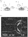
- FIGS. 1 to 5 show a bonding interface evaluation device and a bonding interface evaluation method of the embodiment of the present invention.
- the bonding interface evaluation device 10 of the embodiment of the present invention is for evaluating a joined state of a bonding interface 2 between materials 1a and 1b and includes a probe 11 and analysis evaluation means 12.
- the probe 11 is provided to be able to transmit and receive ultrasound and constitutes transmission means and reception means.
- the probe 11 includes a small-area sound source having a diameter of 3 to 10 mm or less and transmits an ultrasonic longitudinal wave from a surface of one material 1a, whereby the longitudinal wave is converted into a transverse wave by the surface of the material 1a and that transverse wave can also propagate in the material 1a.
- the probe 11 is configured to be able to simultaneously transmit the ultrasonic longitudinal wave and transverse wave in a substantially perpendicular direction to the bonding interface 2 to be evaluated.
- the probe 11 is configured to be able to receive a reflection signal of the transmitted longitudinal wave reflected by the bonding interface 2 and a transmission signal of the transmitted longitudinal wave transmitted through the bonding interface 2 and a reflection signal of the transmitted transverse wave reflected by the bonding interface 2 and a transmission signal of the transmitted transverse wave transmitted through the bonding interface 2.
- the transmission signals are signals representing the longitudinal wave and the transverse wave transmitted from the surface of the one material 1a, transmitted through the bonding interface 2, reflected by a surface on an opposite side of the other material 1b and transmitted through the bonding interface 2 again.
- the transmission means may be the one capable of transmitting only the transverse wave, other than the probe 11.
- the reception means may be the one capable of receiving only the transverse wave, other than the probe 11.
- the analysis evaluation means 12 is constituted by a computer and configured to evaluate the joined state of the bonding interface 2, utilizing the signals received by the probe 11. Specifically, the analysis evaluation means 12 is configured to evaluate the joined state of the bonding interface 2 by an amplitude intensity of the transmission signal of the transverse wave and that of the reflection signal of the transverse wave, out of the received signals.
- the analysis evaluation means 12 is configured to utilize at least one pair of amplitude intensities, out of the amplitude intensity of the transmission signal of the transverse wave and that of the reflection signal of the transverse wave, an amplitude intensity of the transmission signal of the longitudinal wave and that of the transmission signal of the transverse wave, the amplitude intensity of the transmission signal of the longitudinal wave and that of the reflection signal of the transverse wave, an amplitude intensity of the reflection signal of the longitudinal wave and that of the transmission signal of the transverse wave, and the amplitude intensity of the reflection signal of the longitudinal wave and that of the reflection signal of the transverse wave among the received signals, obtain a difference or a ratio of those two amplitude intensities and evaluate the joined state of the bonding interface 2 by the magnitude of that difference or ratio. It should be noted that, without limitation to amplitude intensities, waveforms and spectra may be utilized for evaluation.
- the bonding interface evaluation method of the embodiment of the present invention is more suitably carried out by the bonding interface evaluation device 10.
- the probe 11 is disposed on the surface of the one material 1a for the bonding interface 2 between the materials 1a and 1b to be evaluated as shown in FIG. 1 .
- Ultrasonic longitudinal wave and transverse wave are simultaneously transmitted in a substantially perpendicular direction to the bonding interface 2 from the disposed probe 11.
- a reflection signal of the transmitted longitudinal wave reflected by the bonding interface 2 and a transmission signal of the transmitted longitudinal wave transmitted through the bonding interface 2 and a reflection signal of the transmitted transverse wave reflected by the bonding interface 2 and a transmission signal of the transmitted transverse wave transmitted through the bonding interface 2 are received by the probe 11.
- the amplitude intensity of the transmission signal of the transverse wave and that of the reflection signal of the transverse wave, out of the signals received by the probe 11, are obtained by the analysis evaluation means 12.
- the longitudinal wave and the transverse wave are hardly reflected by that interface and the amplitude intensities of the transmission signals increase. Further, if the interface is open and completely unjoined, the longitudinal wave and the transverse wave are reflected by that interface, wherefore the amplitude intensities of the reflection signals increase. Further, since the longitudinal wave, which is a compressional wave, easily transmits through the interface where the materials 1a, 1b are in contact, but not joined as in a kissing bond or a coronabond shown in FIG.
- a detailed joined state such as whether or not the materials 1a, 1b are in contact, the interface is open, or the interface is joined although the materials 1a, 1b are in contact, can be evaluated using the amplitude intensities of the transmission signal and the reflection signal of the transverse wave or the magnitude of the difference or ratio of the two amplitude intensities obtained by the analysis evaluation means 12. Further, if measurement data under specific bonding conditions is collected, the evaluation of bonding strength can be expected.
- the bonding interface evaluation method and the bonding interface evaluation device 10 of the embodiment of the present invention can precisely evaluate even a joined state of an unjoined part such as the kissing bond or coronabond shown in FIG. 1(B) . Further, the joined state can be evaluated by transmitting the longitudinal wave and the transverse wave and receiving the reflection signals and the transmission signals by one probe 11.
- the wavefronts of not only the longitudinal wave, but also a transverse wave, a head wave and surface waves (SSCW, etc.) are confirmed. From this, it can be said that the incidence efficiency of the transverse wave becomes relatively high and the longitudinal wave and the transverse wave are easily incident from a specimen surface if an incident area is small such in the case of a point sound source or a line sound source, wherefore a joined state can be evaluated by measuring reflection signals and transmission signals.
- FIG. 3(C) an image showing the position (position of a transverse line in a figure) of the transmission signal of the transverse wave (transmitted transverse wave) in the obtained B-scope image is shown in FIG. 3(C)
- FIG. 3(D) an image showing the position of a longitudinal line in the B-scope image is shown in FIG. 3(D) .
- the transmission signals of the longitudinal wave and the transverse wave were clearly confirmed.
- FIG. 4(A) In the experiment, the longitudinal wave was transmitted with the probe 11 placed on a steel plate and a reflection echo on the underside of the steel plate was measured, using two types of probes 11 having diameters of 30 mm and 6 mm. Measurement results by the respective probes 11 having the diameters of 30 mm and 6 mm are respectively shown in FIG. 4(B) and (C) .
- a waveform of P in FIG. 4(B) and (C) is a longitudinal wave reflection echo of longitudinal wave incidence
- a waveform of S is a transverse wave reflection echo of transverse wave incidence.
- the bonding interface evaluation method and the bonding interface evaluation device 10 of the embodiment of the present invention can evaluate a joined state of any interface if the interface is a bonding interface between materials, and can be applied to the evaluation of not only the bonding interface 2 of spot welding as shown in FIG. 1 , but also, for example, bonding interfaces difficult to evaluate by an acoustic measurement using only a longitudinal wave, out of bonding interfaces between materials joined by bonding, various types of welding such as FSW (Friction Stir Welding), pressure bonding, diffusion bonding and the like.
- FSW Frriction Stir Welding
- the bonding interface evaluation method and the bonding interface evaluation device 10 of the embodiment of the present invention may include a plurality of probes 11, transmit a longitudinal wave and a transverse wave from each probe 11 and receive reflection signals and transmission signals of the longitudinal wave and the transverse wave transmitted from each probe 11 by each probe 11.
- the joined state of the bonding interface 2 can be more accurately evaluated, utilizing a survey method or a flaw detection method using the plurality of probes 11 such as a phased array method.
- a joined state can be accurately evaluated by measuring and using also an acoustic image of a transverse wave in addition to an existing measurement using longitudinal wave ultrasound.
- a transmission signal of the longitudinal wave and a transmission signal of the transverse wave were measured for the bonding interface 2 formed by spot-welding the materials 1a, 1b.
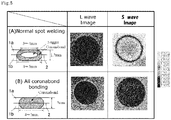
- the measurement was conducted for simulated materials having a structure in which a nugget was formed in a spot-welded part and a coronabond was formed around the nugget as shown in FIG. 5(A) and a structure in which no nugget is formed in a spot-welded part and a bonding interface is entirely a coronabond as shown in FIG. 5(B) .
- a water immersion imaging method utilizing ultrasound shown in non-patent literature 1 was used for the measurement.
- the longitudinal wave is transmitted in a perpendicular direction from a surface (upper surface in FIGS. 5(A) and (B) ) of one material 1a by a standard acoustic lens for water immersion measurement.
- this acoustic lens also generates a transverse wave by converting the longitudinal wave on the surface of the one material 1a, but the transverse wave can be ignored here since the intensity thereof is small.
- L wave longitudinal wave
- a longitudinal wave reflected wave amplitude on the bonding interface 2 was extracted at an electric gate and imaged in accordance with an existing standard bonding interface evaluation procedure. That image (L wave image) is shown in FIG. 5(A) and (B) .
- FIG. 5(A) whereas an acoustic image was black in a central part and the transverse wave was not transmitted in the coronabond part having no bonding strength although being held in close contact as shown in FIG. 5(B) .
- the structures of FIG. 5(A) and (B) are difficult to discriminate in the existing longitudinal wave acoustic image (L wave image), whereas these structures can be evaluated with sound bonding and unsound bonding distinguished if the transverse wave acoustic image (S wave image) is utilized.
- the measurement of the transverse wave which is a shear wave
- the longitudinal wave which is a compressional wave
- the bonding interface evaluation method and the bonding interface evaluation device propose a bonding interface acoustic measurement/evaluation method having a high versatility by including direct contact of a probe and using a mode converted transverse wave generated when longitudinal wave ultrasound is incident in a small area singly or together with the longitudinal wave for measurement.
Landscapes
- Physics & Mathematics (AREA)
- Biochemistry (AREA)
- Health & Medical Sciences (AREA)
- Life Sciences & Earth Sciences (AREA)
- Chemical & Material Sciences (AREA)
- Analytical Chemistry (AREA)
- General Health & Medical Sciences (AREA)
- General Physics & Mathematics (AREA)
- Immunology (AREA)
- Pathology (AREA)
- Acoustics & Sound (AREA)
- Engineering & Computer Science (AREA)
- Signal Processing (AREA)
- Investigating Or Analyzing Materials By The Use Of Ultrasonic Waves (AREA)
Applications Claiming Priority (2)
| Application Number | Priority Date | Filing Date | Title |
|---|---|---|---|
| JP2018155605 | 2018-08-22 | ||
| PCT/JP2019/029575 WO2020039850A1 (ja) | 2018-08-22 | 2019-07-29 | 接合界面の評価方法および接合界面の評価装置 |
Publications (3)
| Publication Number | Publication Date |
|---|---|
| EP3842797A1 true EP3842797A1 (de) | 2021-06-30 |
| EP3842797A4 EP3842797A4 (de) | 2021-09-22 |
| EP3842797B1 EP3842797B1 (de) | 2023-12-27 |
Family
ID=69592781
Family Applications (1)
| Application Number | Title | Priority Date | Filing Date |
|---|---|---|---|
| EP19851786.4A Active EP3842797B1 (de) | 2018-08-22 | 2019-07-29 | Verfahren und vorrichtung zur auswertung einer bindungsschnittstelle |
Country Status (5)
| Country | Link |
|---|---|
| US (1) | US11898990B2 (de) |
| EP (1) | EP3842797B1 (de) |
| JP (1) | JP7353545B2 (de) |
| CN (1) | CN112534254B (de) |
| WO (1) | WO2020039850A1 (de) |
Families Citing this family (5)
| Publication number | Priority date | Publication date | Assignee | Title |
|---|---|---|---|---|
| US11346816B2 (en) * | 2020-05-01 | 2022-05-31 | The Boeing Company | Apparatuses, systems, and methods for detecting kissing bonds in bonded joints |
| JP7783701B2 (ja) * | 2021-06-28 | 2025-12-10 | 東芝検査ソリューションズ株式会社 | 超音波検査装置、方法及びプログラム |
| CN113607818B (zh) * | 2021-08-04 | 2024-02-27 | 中北大学 | 一种多界面粘接质量超声检测装置及方法 |
| US12205855B2 (en) * | 2021-08-26 | 2025-01-21 | Taiwan Semiconductor Manufacturing Company, Ltd. | Process tool for analyzing bonded workpiece interface |
| CN113640217B (zh) * | 2021-10-13 | 2022-01-21 | 武汉地震工程研究院有限公司 | 一种粘钢法混凝土界面粘结状态监测系统 |
Family Cites Families (12)
| Publication number | Priority date | Publication date | Assignee | Title |
|---|---|---|---|---|
| JPS60228959A (ja) | 1984-04-26 | 1985-11-14 | Hashimoto Forming Co Ltd | スポツト溶接部の良否判定方法 |
| JPS62148850A (ja) | 1985-12-24 | 1987-07-02 | Kawasaki Steel Corp | 鋳片の凝固状態検出方法 |
| GB2232487B (en) * | 1989-06-09 | 1993-08-04 | Shimizu Construction Co Ltd | Ultrasonic measuring apparatus including a high-damping probe |
| JP3140157B2 (ja) | 1992-04-09 | 2001-03-05 | 川崎重工業株式会社 | 面状欠陥の超音波探傷方法 |
| JPH08211028A (ja) * | 1995-02-03 | 1996-08-20 | Hitachi Constr Mach Co Ltd | 超音波探傷方法および装置 |
| JP4067203B2 (ja) | 1998-11-11 | 2008-03-26 | 日産自動車株式会社 | スポット溶接の検査方法 |
| JP3735006B2 (ja) | 2000-04-21 | 2006-01-11 | 独立行政法人科学技術振興機構 | 非線形超音波を用いた内部微視亀裂検出方法及び装置 |
| ATE334774T1 (de) | 2002-12-18 | 2006-08-15 | Fraunhofer Ges Forschung | Verfahren zur bewertung einer sich während eines schweissvorganges ausbildenden schweissverbindung mit longitudinalen und transversalen ultraschallwellen |
| JP4244334B2 (ja) * | 2004-08-27 | 2009-03-25 | 有限会社超音波材料診断研究所 | 超音波材料評価装置 |
| JP2006084305A (ja) | 2004-09-15 | 2006-03-30 | Daido Steel Co Ltd | 材料欠陥検出方法および装置 |
| JP2010243268A (ja) * | 2009-04-03 | 2010-10-28 | Hitachi Ltd | 溶射膜の密着性検査方法およびその装置 |
| JP2013036743A (ja) * | 2011-08-03 | 2013-02-21 | Honda Motor Co Ltd | スポット溶接の溶融検査方法 |
-
2019
- 2019-07-29 EP EP19851786.4A patent/EP3842797B1/de active Active
- 2019-07-29 CN CN201980052436.6A patent/CN112534254B/zh active Active
- 2019-07-29 JP JP2020538257A patent/JP7353545B2/ja active Active
- 2019-07-29 WO PCT/JP2019/029575 patent/WO2020039850A1/ja not_active Ceased
- 2019-07-29 US US17/270,381 patent/US11898990B2/en active Active
Also Published As
| Publication number | Publication date |
|---|---|
| US11898990B2 (en) | 2024-02-13 |
| JP7353545B2 (ja) | 2023-10-02 |
| CN112534254B (zh) | 2024-11-19 |
| JPWO2020039850A1 (ja) | 2021-08-26 |
| EP3842797A4 (de) | 2021-09-22 |
| WO2020039850A1 (ja) | 2020-02-27 |
| US20210181153A1 (en) | 2021-06-17 |
| CN112534254A (zh) | 2021-03-19 |
| EP3842797B1 (de) | 2023-12-27 |
Similar Documents
| Publication | Publication Date | Title |
|---|---|---|
| US11898990B2 (en) | Bonding interface evaluation method and bonding interface evaluation device | |
| JP4470655B2 (ja) | 超音波によるスポット溶接部の評価方法及び装置 | |
| US8590766B2 (en) | Method and apparatus for inspecting joined object formed by friction stir joining | |
| CN105699492A (zh) | 一种用于焊缝检测的超声成像方法 | |
| JP6460136B2 (ja) | 超音波探傷装置及び超音波探傷方法 | |
| US8322221B1 (en) | Non-contact high resolution near field acoustic imaging system | |
| JP4166222B2 (ja) | 超音波探傷方法及び装置 | |
| JP4602421B2 (ja) | 超音波探傷装置 | |
| JP2006234701A (ja) | 超音波探傷装置及び超音波探傷装置方法 | |
| JP4728838B2 (ja) | 超音波によるスポット溶接部の評価方法及び装置 | |
| KR20200011835A (ko) | 배열형 초음파 센서를 이용한 펄스 에코형 비선형 검사 장치 | |
| JP4559931B2 (ja) | 超音波探傷方法 | |
| JP2007003197A (ja) | 超音波材料診断方法及び装置 | |
| JP4098070B2 (ja) | 超音波探傷装置 | |
| JP4731358B2 (ja) | 超音波によるスポット溶接部の評価方法及び装置 | |
| JP3754669B2 (ja) | 超音波探傷装置及び超音波探傷方法 | |
| JP5421544B2 (ja) | 超音波によるスポット溶接部の評価方法及び装置 | |
| JP2006084305A (ja) | 材料欠陥検出方法および装置 | |
| JP4761147B2 (ja) | 超音波探傷方法及び装置 | |
| JP2008111742A (ja) | ホイール溶接部の非破壊検査方法及び装置 | |
| CN117723631A (zh) | 不同方向作用力对材料表面裂纹壁接触程度影响的定性检测系统及方法 | |
| Maev | NEW GENERATION OF HIGH RESOLUTION ACOUSTIC IMAGING TECHNIQUE FOR MATERIAL CHARACTERIZATION AND NDT | |
| KR20060129711A (ko) | 탐촉자 병렬 연결 방식을 이용한 관 이음 융착부 검사장치및 그 방법 | |
| JP2019211281A (ja) | 接合部材の検査装置及び検査方法 | |
| JPH09257774A (ja) | 超音波探傷装置の斜角探触子 |
Legal Events
| Date | Code | Title | Description |
|---|---|---|---|
| STAA | Information on the status of an ep patent application or granted ep patent |
Free format text: STATUS: THE INTERNATIONAL PUBLICATION HAS BEEN MADE |
|
| PUAI | Public reference made under article 153(3) epc to a published international application that has entered the european phase |
Free format text: ORIGINAL CODE: 0009012 |
|
| STAA | Information on the status of an ep patent application or granted ep patent |
Free format text: STATUS: REQUEST FOR EXAMINATION WAS MADE |
|
| 17P | Request for examination filed |
Effective date: 20210210 |
|
| AK | Designated contracting states |
Kind code of ref document: A1 Designated state(s): AL AT BE BG CH CY CZ DE DK EE ES FI FR GB GR HR HU IE IS IT LI LT LU LV MC MK MT NL NO PL PT RO RS SE SI SK SM TR |
|
| A4 | Supplementary search report drawn up and despatched |
Effective date: 20210824 |
|
| RIC1 | Information provided on ipc code assigned before grant |
Ipc: G01N 29/04 20060101AFI20210818BHEP |
|
| RIC1 | Information provided on ipc code assigned before grant |
Ipc: G01N 29/11 20060101ALI20211008BHEP Ipc: G01N 29/04 20060101AFI20211008BHEP |
|
| DAV | Request for validation of the european patent (deleted) | ||
| DAX | Request for extension of the european patent (deleted) | ||
| STAA | Information on the status of an ep patent application or granted ep patent |
Free format text: STATUS: EXAMINATION IS IN PROGRESS |
|
| 17Q | First examination report despatched |
Effective date: 20230731 |
|
| GRAP | Despatch of communication of intention to grant a patent |
Free format text: ORIGINAL CODE: EPIDOSNIGR1 |
|
| STAA | Information on the status of an ep patent application or granted ep patent |
Free format text: STATUS: GRANT OF PATENT IS INTENDED |
|
| INTG | Intention to grant announced |
Effective date: 20230904 |
|
| RAP1 | Party data changed (applicant data changed or rights of an application transferred) |
Owner name: SHIMANE UNIVERSITY |
|
| GRAS | Grant fee paid |
Free format text: ORIGINAL CODE: EPIDOSNIGR3 |
|
| GRAA | (expected) grant |
Free format text: ORIGINAL CODE: 0009210 |
|
| STAA | Information on the status of an ep patent application or granted ep patent |
Free format text: STATUS: THE PATENT HAS BEEN GRANTED |
|
| AK | Designated contracting states |
Kind code of ref document: B1 Designated state(s): AL AT BE BG CH CY CZ DE DK EE ES FI FR GB GR HR HU IE IS IT LI LT LU LV MC MK MT NL NO PL PT RO RS SE SI SK SM TR |
|
| REG | Reference to a national code |
Ref country code: GB Ref legal event code: FG4D |
|
| REG | Reference to a national code |
Ref country code: CH Ref legal event code: EP |
|
| REG | Reference to a national code |
Ref country code: DE Ref legal event code: R096 Ref document number: 602019044204 Country of ref document: DE |
|
| REG | Reference to a national code |
Ref country code: IE Ref legal event code: FG4D |
|
| PG25 | Lapsed in a contracting state [announced via postgrant information from national office to epo] |
Ref country code: GR Free format text: LAPSE BECAUSE OF FAILURE TO SUBMIT A TRANSLATION OF THE DESCRIPTION OR TO PAY THE FEE WITHIN THE PRESCRIBED TIME-LIMIT Effective date: 20240328 |
|
| REG | Reference to a national code |
Ref country code: LT Ref legal event code: MG9D |
|
| PG25 | Lapsed in a contracting state [announced via postgrant information from national office to epo] |
Ref country code: LT Free format text: LAPSE BECAUSE OF FAILURE TO SUBMIT A TRANSLATION OF THE DESCRIPTION OR TO PAY THE FEE WITHIN THE PRESCRIBED TIME-LIMIT Effective date: 20231227 |
|
| PG25 | Lapsed in a contracting state [announced via postgrant information from national office to epo] |
Ref country code: ES Free format text: LAPSE BECAUSE OF FAILURE TO SUBMIT A TRANSLATION OF THE DESCRIPTION OR TO PAY THE FEE WITHIN THE PRESCRIBED TIME-LIMIT Effective date: 20231227 |
|
| PG25 | Lapsed in a contracting state [announced via postgrant information from national office to epo] |
Ref country code: LT Free format text: LAPSE BECAUSE OF FAILURE TO SUBMIT A TRANSLATION OF THE DESCRIPTION OR TO PAY THE FEE WITHIN THE PRESCRIBED TIME-LIMIT Effective date: 20231227 Ref country code: GR Free format text: LAPSE BECAUSE OF FAILURE TO SUBMIT A TRANSLATION OF THE DESCRIPTION OR TO PAY THE FEE WITHIN THE PRESCRIBED TIME-LIMIT Effective date: 20240328 Ref country code: FI Free format text: LAPSE BECAUSE OF FAILURE TO SUBMIT A TRANSLATION OF THE DESCRIPTION OR TO PAY THE FEE WITHIN THE PRESCRIBED TIME-LIMIT Effective date: 20231227 Ref country code: ES Free format text: LAPSE BECAUSE OF FAILURE TO SUBMIT A TRANSLATION OF THE DESCRIPTION OR TO PAY THE FEE WITHIN THE PRESCRIBED TIME-LIMIT Effective date: 20231227 Ref country code: BG Free format text: LAPSE BECAUSE OF FAILURE TO SUBMIT A TRANSLATION OF THE DESCRIPTION OR TO PAY THE FEE WITHIN THE PRESCRIBED TIME-LIMIT Effective date: 20240327 |
|
| REG | Reference to a national code |
Ref country code: NL Ref legal event code: MP Effective date: 20231227 |
|
| REG | Reference to a national code |
Ref country code: AT Ref legal event code: MK05 Ref document number: 1644981 Country of ref document: AT Kind code of ref document: T Effective date: 20231227 |
|
| PG25 | Lapsed in a contracting state [announced via postgrant information from national office to epo] |
Ref country code: NL Free format text: LAPSE BECAUSE OF FAILURE TO SUBMIT A TRANSLATION OF THE DESCRIPTION OR TO PAY THE FEE WITHIN THE PRESCRIBED TIME-LIMIT Effective date: 20231227 |
|
| PG25 | Lapsed in a contracting state [announced via postgrant information from national office to epo] |
Ref country code: SE Free format text: LAPSE BECAUSE OF FAILURE TO SUBMIT A TRANSLATION OF THE DESCRIPTION OR TO PAY THE FEE WITHIN THE PRESCRIBED TIME-LIMIT Effective date: 20231227 Ref country code: RS Free format text: LAPSE BECAUSE OF FAILURE TO SUBMIT A TRANSLATION OF THE DESCRIPTION OR TO PAY THE FEE WITHIN THE PRESCRIBED TIME-LIMIT Effective date: 20231227 Ref country code: NO Free format text: LAPSE BECAUSE OF FAILURE TO SUBMIT A TRANSLATION OF THE DESCRIPTION OR TO PAY THE FEE WITHIN THE PRESCRIBED TIME-LIMIT Effective date: 20240327 Ref country code: NL Free format text: LAPSE BECAUSE OF FAILURE TO SUBMIT A TRANSLATION OF THE DESCRIPTION OR TO PAY THE FEE WITHIN THE PRESCRIBED TIME-LIMIT Effective date: 20231227 Ref country code: LV Free format text: LAPSE BECAUSE OF FAILURE TO SUBMIT A TRANSLATION OF THE DESCRIPTION OR TO PAY THE FEE WITHIN THE PRESCRIBED TIME-LIMIT Effective date: 20231227 Ref country code: HR Free format text: LAPSE BECAUSE OF FAILURE TO SUBMIT A TRANSLATION OF THE DESCRIPTION OR TO PAY THE FEE WITHIN THE PRESCRIBED TIME-LIMIT Effective date: 20231227 |
|
| PG25 | Lapsed in a contracting state [announced via postgrant information from national office to epo] |
Ref country code: IS Free format text: LAPSE BECAUSE OF FAILURE TO SUBMIT A TRANSLATION OF THE DESCRIPTION OR TO PAY THE FEE WITHIN THE PRESCRIBED TIME-LIMIT Effective date: 20240427 |
|
| PG25 | Lapsed in a contracting state [announced via postgrant information from national office to epo] |
Ref country code: CZ Free format text: LAPSE BECAUSE OF FAILURE TO SUBMIT A TRANSLATION OF THE DESCRIPTION OR TO PAY THE FEE WITHIN THE PRESCRIBED TIME-LIMIT Effective date: 20231227 Ref country code: AT Free format text: LAPSE BECAUSE OF FAILURE TO SUBMIT A TRANSLATION OF THE DESCRIPTION OR TO PAY THE FEE WITHIN THE PRESCRIBED TIME-LIMIT Effective date: 20231227 |
|
| PG25 | Lapsed in a contracting state [announced via postgrant information from national office to epo] |
Ref country code: SK Free format text: LAPSE BECAUSE OF FAILURE TO SUBMIT A TRANSLATION OF THE DESCRIPTION OR TO PAY THE FEE WITHIN THE PRESCRIBED TIME-LIMIT Effective date: 20231227 |
|
| PG25 | Lapsed in a contracting state [announced via postgrant information from national office to epo] |
Ref country code: SM Free format text: LAPSE BECAUSE OF FAILURE TO SUBMIT A TRANSLATION OF THE DESCRIPTION OR TO PAY THE FEE WITHIN THE PRESCRIBED TIME-LIMIT Effective date: 20231227 Ref country code: SK Free format text: LAPSE BECAUSE OF FAILURE TO SUBMIT A TRANSLATION OF THE DESCRIPTION OR TO PAY THE FEE WITHIN THE PRESCRIBED TIME-LIMIT Effective date: 20231227 Ref country code: RO Free format text: LAPSE BECAUSE OF FAILURE TO SUBMIT A TRANSLATION OF THE DESCRIPTION OR TO PAY THE FEE WITHIN THE PRESCRIBED TIME-LIMIT Effective date: 20231227 Ref country code: IT Free format text: LAPSE BECAUSE OF FAILURE TO SUBMIT A TRANSLATION OF THE DESCRIPTION OR TO PAY THE FEE WITHIN THE PRESCRIBED TIME-LIMIT Effective date: 20231227 Ref country code: IS Free format text: LAPSE BECAUSE OF FAILURE TO SUBMIT A TRANSLATION OF THE DESCRIPTION OR TO PAY THE FEE WITHIN THE PRESCRIBED TIME-LIMIT Effective date: 20240427 Ref country code: EE Free format text: LAPSE BECAUSE OF FAILURE TO SUBMIT A TRANSLATION OF THE DESCRIPTION OR TO PAY THE FEE WITHIN THE PRESCRIBED TIME-LIMIT Effective date: 20231227 Ref country code: CZ Free format text: LAPSE BECAUSE OF FAILURE TO SUBMIT A TRANSLATION OF THE DESCRIPTION OR TO PAY THE FEE WITHIN THE PRESCRIBED TIME-LIMIT Effective date: 20231227 Ref country code: AT Free format text: LAPSE BECAUSE OF FAILURE TO SUBMIT A TRANSLATION OF THE DESCRIPTION OR TO PAY THE FEE WITHIN THE PRESCRIBED TIME-LIMIT Effective date: 20231227 |
|
| PG25 | Lapsed in a contracting state [announced via postgrant information from national office to epo] |
Ref country code: PT Free format text: LAPSE BECAUSE OF FAILURE TO SUBMIT A TRANSLATION OF THE DESCRIPTION OR TO PAY THE FEE WITHIN THE PRESCRIBED TIME-LIMIT Effective date: 20240429 Ref country code: PL Free format text: LAPSE BECAUSE OF FAILURE TO SUBMIT A TRANSLATION OF THE DESCRIPTION OR TO PAY THE FEE WITHIN THE PRESCRIBED TIME-LIMIT Effective date: 20231227 |
|
| PG25 | Lapsed in a contracting state [announced via postgrant information from national office to epo] |
Ref country code: PT Free format text: LAPSE BECAUSE OF FAILURE TO SUBMIT A TRANSLATION OF THE DESCRIPTION OR TO PAY THE FEE WITHIN THE PRESCRIBED TIME-LIMIT Effective date: 20240429 Ref country code: PL Free format text: LAPSE BECAUSE OF FAILURE TO SUBMIT A TRANSLATION OF THE DESCRIPTION OR TO PAY THE FEE WITHIN THE PRESCRIBED TIME-LIMIT Effective date: 20231227 |
|
| REG | Reference to a national code |
Ref country code: DE Ref legal event code: R097 Ref document number: 602019044204 Country of ref document: DE |
|
| PG25 | Lapsed in a contracting state [announced via postgrant information from national office to epo] |
Ref country code: DK Free format text: LAPSE BECAUSE OF FAILURE TO SUBMIT A TRANSLATION OF THE DESCRIPTION OR TO PAY THE FEE WITHIN THE PRESCRIBED TIME-LIMIT Effective date: 20231227 |
|
| PG25 | Lapsed in a contracting state [announced via postgrant information from national office to epo] |
Ref country code: DK Free format text: LAPSE BECAUSE OF FAILURE TO SUBMIT A TRANSLATION OF THE DESCRIPTION OR TO PAY THE FEE WITHIN THE PRESCRIBED TIME-LIMIT Effective date: 20231227 |
|
| PLBE | No opposition filed within time limit |
Free format text: ORIGINAL CODE: 0009261 |
|
| STAA | Information on the status of an ep patent application or granted ep patent |
Free format text: STATUS: NO OPPOSITION FILED WITHIN TIME LIMIT |
|
| 26N | No opposition filed |
Effective date: 20240930 |
|
| PG25 | Lapsed in a contracting state [announced via postgrant information from national office to epo] |
Ref country code: MC Free format text: LAPSE BECAUSE OF FAILURE TO SUBMIT A TRANSLATION OF THE DESCRIPTION OR TO PAY THE FEE WITHIN THE PRESCRIBED TIME-LIMIT Effective date: 20231227 |
|
| REG | Reference to a national code |
Ref country code: CH Ref legal event code: PL |
|
| PG25 | Lapsed in a contracting state [announced via postgrant information from national office to epo] |
Ref country code: LU Free format text: LAPSE BECAUSE OF NON-PAYMENT OF DUE FEES Effective date: 20240729 |
|
| GBPC | Gb: european patent ceased through non-payment of renewal fee |
Effective date: 20240729 |
|
| PG25 | Lapsed in a contracting state [announced via postgrant information from national office to epo] |
Ref country code: LU Free format text: LAPSE BECAUSE OF NON-PAYMENT OF DUE FEES Effective date: 20240729 |
|
| PG25 | Lapsed in a contracting state [announced via postgrant information from national office to epo] |
Ref country code: BE Free format text: LAPSE BECAUSE OF NON-PAYMENT OF DUE FEES Effective date: 20240731 Ref country code: CH Free format text: LAPSE BECAUSE OF NON-PAYMENT OF DUE FEES Effective date: 20240731 Ref country code: SI Free format text: LAPSE BECAUSE OF FAILURE TO SUBMIT A TRANSLATION OF THE DESCRIPTION OR TO PAY THE FEE WITHIN THE PRESCRIBED TIME-LIMIT Effective date: 20231227 |
|
| PG25 | Lapsed in a contracting state [announced via postgrant information from national office to epo] |
Ref country code: GB Free format text: LAPSE BECAUSE OF NON-PAYMENT OF DUE FEES Effective date: 20240729 |
|
| REG | Reference to a national code |
Ref country code: BE Ref legal event code: MM Effective date: 20240731 |
|
| PG25 | Lapsed in a contracting state [announced via postgrant information from national office to epo] |
Ref country code: IE Free format text: LAPSE BECAUSE OF NON-PAYMENT OF DUE FEES Effective date: 20240729 |
|
| PGFP | Annual fee paid to national office [announced via postgrant information from national office to epo] |
Ref country code: DE Payment date: 20250722 Year of fee payment: 7 |
|
| PGFP | Annual fee paid to national office [announced via postgrant information from national office to epo] |
Ref country code: FR Payment date: 20250725 Year of fee payment: 7 |
|
| PG25 | Lapsed in a contracting state [announced via postgrant information from national office to epo] |
Ref country code: CY Free format text: LAPSE BECAUSE OF FAILURE TO SUBMIT A TRANSLATION OF THE DESCRIPTION OR TO PAY THE FEE WITHIN THE PRESCRIBED TIME-LIMIT; INVALID AB INITIO Effective date: 20190729 |
|
| PG25 | Lapsed in a contracting state [announced via postgrant information from national office to epo] |
Ref country code: HU Free format text: LAPSE BECAUSE OF FAILURE TO SUBMIT A TRANSLATION OF THE DESCRIPTION OR TO PAY THE FEE WITHIN THE PRESCRIBED TIME-LIMIT; INVALID AB INITIO Effective date: 20190729 |