EP3842876B1 - Uhr, die mit einem mechanischen uhrwerk und einer vorrichtung zur korrektur der angezeigten stunde ausgestattet ist - Google Patents
Uhr, die mit einem mechanischen uhrwerk und einer vorrichtung zur korrektur der angezeigten stunde ausgestattet ist Download PDFInfo
- Publication number
- EP3842876B1 EP3842876B1 EP20194692.8A EP20194692A EP3842876B1 EP 3842876 B1 EP3842876 B1 EP 3842876B1 EP 20194692 A EP20194692 A EP 20194692A EP 3842876 B1 EP3842876 B1 EP 3842876B1
- Authority
- EP
- European Patent Office
- Prior art keywords
- time
- correction
- mechanical resonator
- indicator
- braking
- Prior art date
- Legal status (The legal status is an assumption and is not a legal conclusion. Google has not performed a legal analysis and makes no representation as to the accuracy of the status listed.)
- Active
Links
Images




Classifications
-
- G—PHYSICS
- G04—HOROLOGY
- G04B—MECHANICALLY-DRIVEN CLOCKS OR WATCHES; MECHANICAL PARTS OF CLOCKS OR WATCHES IN GENERAL; TIME PIECES USING THE POSITION OF THE SUN, MOON OR STARS
- G04B18/00—Mechanisms for setting frequency
- G04B18/02—Regulator or adjustment devices; Indexing devices, e.g. raquettes
- G04B18/028—Setting the regulator by means coupled to or depending on another device, e.g. by the time indication setting mechanism
-
- G—PHYSICS
- G04—HOROLOGY
- G04C—ELECTROMECHANICAL CLOCKS OR WATCHES
- G04C11/00—Synchronisation of independently-driven clocks
- G04C11/08—Synchronisation of independently-driven clocks using an electro-magnet or-motor for oscillation correction
- G04C11/081—Synchronisation of independently-driven clocks using an electro-magnet or-motor for oscillation correction using an electro-magnet
- G04C11/084—Synchronisation of independently-driven clocks using an electro-magnet or-motor for oscillation correction using an electro-magnet acting on the balance
-
- G—PHYSICS
- G04—HOROLOGY
- G04B—MECHANICALLY-DRIVEN CLOCKS OR WATCHES; MECHANICAL PARTS OF CLOCKS OR WATCHES IN GENERAL; TIME PIECES USING THE POSITION OF THE SUN, MOON OR STARS
- G04B15/00—Escapements
- G04B15/14—Component parts or constructional details, e.g. construction of the lever or the escape wheel
-
- G—PHYSICS
- G04—HOROLOGY
- G04B—MECHANICALLY-DRIVEN CLOCKS OR WATCHES; MECHANICAL PARTS OF CLOCKS OR WATCHES IN GENERAL; TIME PIECES USING THE POSITION OF THE SUN, MOON OR STARS
- G04B17/00—Mechanisms for stabilising frequency
- G04B17/04—Oscillators acting by spring tension
- G04B17/06—Oscillators with hairsprings, e.g. balance
- G04B17/063—Balance construction
-
- G—PHYSICS
- G04—HOROLOGY
- G04B—MECHANICALLY-DRIVEN CLOCKS OR WATCHES; MECHANICAL PARTS OF CLOCKS OR WATCHES IN GENERAL; TIME PIECES USING THE POSITION OF THE SUN, MOON OR STARS
- G04B17/00—Mechanisms for stabilising frequency
- G04B17/32—Component parts or constructional details, e.g. collet, stud, virole or piton
- G04B17/34—Component parts or constructional details, e.g. collet, stud, virole or piton for fastening the hairspring onto the balance
-
- G—PHYSICS
- G04—HOROLOGY
- G04B—MECHANICALLY-DRIVEN CLOCKS OR WATCHES; MECHANICAL PARTS OF CLOCKS OR WATCHES IN GENERAL; TIME PIECES USING THE POSITION OF THE SUN, MOON OR STARS
- G04B27/00—Mechanical devices for setting the time indicating means
- G04B27/007—Mechanical devices for setting the time indicating means otherwise than manually
-
- G—PHYSICS
- G04—HOROLOGY
- G04R—RADIO-CONTROLLED TIME-PIECES
- G04R20/00—Setting the time according to the time information carried or implied by the radio signal
- G04R20/02—Setting the time according to the time information carried or implied by the radio signal the radio signal being sent by a satellite, e.g. GPS
-
- G—PHYSICS
- G04—HOROLOGY
- G04R—RADIO-CONTROLLED TIME-PIECES
- G04R20/00—Setting the time according to the time information carried or implied by the radio signal
- G04R20/26—Setting the time according to the time information carried or implied by the radio signal the radio signal being a near-field communication signal
-
- G—PHYSICS
- G04—HOROLOGY
- G04R—RADIO-CONTROLLED TIME-PIECES
- G04R60/00—Constructional details
- G04R60/14—Constructional details specific to electromechanical timepieces, e.g. moving parts thereof
Definitions
- the present invention relates to a timepiece comprising a mechanical movement, a display of a real time which is driven by this mechanical movement, and a device for correcting this real time displayed.
- the classic way of correcting the real time indicated by its display is to use the classic stem-crown which is generally arranged to be able to act, in the pulled-out position, on a wheel set for driving the hour indicator and the minute indicator, thanks to friction provided in the kinematic chain between these indicators and the escapement wheel.
- a mechanical watch it is generally necessary for the user or a robot to pull the stem-crown and rotate it to bring the hour and minute indicators into the respective desired positions, in particular by a visual comparison with a reference clock, such as those found for example in train stations, or with a digital time given for example by a computer.
- the document EP 3 339 982 discloses a device for regulating the rate of a clock movement equipped with a mechanical oscillator.
- the regulating device comprises an auxiliary quartz oscillator, an optical sensor for detecting the alternations of the mechanical oscillator, a regulating circuit arranged to determine a time drift of the mechanical oscillator relative to the auxiliary oscillator, and a braking device arranged to apply mechanical braking pulses to the balance of the mechanical oscillator, selectively, in different half-waves of an oscillation of this mechanical oscillator depending on whether the time drift is negative or positive.
- the average frequency of the mechanical oscillator is maintained around a reference frequency determined by the auxiliary oscillator.
- the present invention aims to be able to set the time of a timepiece, comprising a mechanical movement and a time display, with a precision corresponding at least to that of an electronic watch, preferably substantially setting this timepiece to the exact real time which is given by an external system arranged to provide it (in particular a system connected to an atomic clock), without requiring a user or a robot to have to actuate a crown stem or another external control member of the timepiece to perform a time setting of the display itself.
- the precision of the time setting of a timepiece equipped with a mechanical movement does not depend on a visual assessment by the user having to estimate when the various indicators concerned are in the correct respective positions.
- the term 'real time' is understood to mean the legal time of a given location, in which the timepiece and its user are generally located.
- the real time is generally displayed in hours, minutes and, where appropriate, seconds.
- the real time may be indicated with a certain error by a timepiece, in particular of the mechanical type.
- the real time will also simply be referred to as 'the time', in particular with regard to the real time displayed by a timepiece.
- the expression 'exact real time' will be used in this text.
- the electronic correction circuit is arranged and the duration of the detection phase is provided to allow the detection device to detect, while the drive mechanism is running and clocked by the oscillating mechanical resonator, at least one passage of said indicator through any reference time position of said at least one reference time position.
- the electronic correction circuit is arranged to be able to determine at least one instant of passage of said indicator through said any reference time position on the basis of at least one measurement value of the plurality of measurement values, this instant of passage being determined by the internal time base and composed at least of the value of said current time unit of reference to said instant of passage.
- Said electronic correction circuit is further arranged to be able to determine a temporal error of said indicator, by comparing said at least one instant of passage with said reference time position, and an overall temporal error for the display (i.e. for all of the indicators) as a function at least of said temporal error of said indicator.
- control unit is arranged to be able to control the braking device as a function of the determined overall time error.
- the device for correcting the actual displayed time is arranged in such a way that, when a non-zero overall time error has been determined by the electronic correction circuit, the braking device can act, during a correction period, on the mechanical resonator, as a function of the overall time error, to vary the operation of the display drive mechanism so as to correct at least part of this overall time error, advantageously a major part of this overall time error and preferably substantially all of it.
- 'braking device' is generally understood any device capable of braking and/or stopping an oscillating mechanical resonator and/or of momentarily maintaining a stop (i.e. blocking) such a resonator.
- the braking device may be formed by one or more braking units (one or more actuators).
- each braking unit is selected to act on the mechanical resonator in a specific situation relating to the required correction, in particular a first braking unit to correct a delay and a second braking unit to correct an advance (the second braking unit being advantageously arranged to be able to stop and momentarily block the resonator).
- 'timing the operation of a drive mechanism of a display' is understood the fact of timing the movement of mobiles of this mechanism when it is operating, in particular of determining the rotation speeds of these mobiles and thus of at least one indicator of the display.
- 'resonator' when used without a specific qualifier, it is to designate a mechanical resonator. We will speak of an oscillating resonator to indicate that we are considering a resonator in its activated state, in which it oscillates while being maintained, via an escapement, by a source of mechanical energy.
- the indicators used to display the real time all concern a single physical quantity, time, in this description the hour, the minute and the second are considered as three different time units since they are respectively associated with three separate indicators.
- the actual time displayed by a display is composed of a current hour, a current minute and a current second which will sometimes be called 'displayed'.
- the current second displayed has an integer part in seconds and possibly one or more decimal places (dial generally without graduation of the decimal place, but the decimal part is a fact in an analog display where the quasi-continuous advance of the hand is normally done in steps cadenced by the escapement at double the frequency of the oscillating resonator).
- the current minute displayed has an integer part in minutes (whole number of minutes) and generally a fractional part (sexagesimal part) in seconds (always the case in an analog display of the actual time).
- the current time displayed includes at least one integer part (and only this integer part with a 'jumping' hour).
- the actual reference time provided by an internal time base of the electronic type is composed of a current reference hour, a current reference minute and a current reference second. These three components are integers.
- the internal time base may optionally provide fractions of a second.
- the internal time base which is of the electronic type, provides a real reference time that may be composed of fewer time units than the real time, in particular containing only the current reference minute and the current reference second, possibly in addition a current fraction of a second generated by a clock circuit that forms this internal time base.
- the display comprises an hour indicator giving the current hour, a minute indicator giving the current minute and a second indicator giving the current second of the actual time displayed; and the actual reference time generated by the internal time base is composed of at least one current reference second and one current reference minute.
- the detection device is arranged to be able to detect the passage of the seconds indicator by at least one first reference time position of the display and the passage of the minutes indicator by at least one second reference time position of this display.
- the electronic correction circuit is arranged and the duration of the detection phase is provided to allow the detection device to detect during this detection phase, while said drive mechanism is running and clocked by the oscillating mechanical resonator, at least one passage of the seconds indicator by a first reference time position of said at least one first reference position and at least one passage of the minutes indicator by a second reference time position of said at least one second reference time position.
- the electronic correction circuit is arranged to be able to determine, in association with the internal time base and on the basis of measurement values of the plurality of measurement values, at least one first instant of passage of the seconds indicator through said first reference time position, this first instant of passage being determined by the real reference time and composed of at least the value of the current reference second at said first instant of passage, and at least one second instant of passage of the minutes indicator through said second reference time position, this second instant of passage also being determined by the real reference time and composed of at least the value of the current reference minute at said second instant of passage.
- the processing unit or the control unit is arranged to be able to determine a first time error for the seconds indicator, by comparing said at least one first instant of passage with the first reference time position, and a second time error for the minutes indicator by comparing said at least one second instant of passage with the second reference time position.
- the processing unit or control unit is further arranged to be able to determine an overall time error for the display in function of the first time error and the second time error as well as at least one predetermined processing criterion for these first and second time errors.
- the detection device is activated so as to carry out the plurality of successive measurements at at least one measurement frequency determined by the clock circuit of the internal time base, this clock circuit providing a periodic digital signal at the measurement frequency directly to the detection device or indirectly to this detection device via the control unit.
- the detection device is arranged in the timepiece so as to be able to perform direct detection of the passage of an indicator of the display through at least one corresponding reference time position, this indicator being arranged so as to be able to be detected itself by the detection device.
- the detection device is arranged in the timepiece so as to be able to perform indirect detection of the passage of an indicator of the display through at least one corresponding reference time position, the detection device being arranged to be able to detect at least one respective angular position of a wheel secured to the indicator or of a detection wheel, forming the drive mechanism or complementary thereto, which drives or is driven by the wheel secured to the indicator, the detection wheel being selected or configured so as to have a rotation speed lower than that of the wheel secured to the indicator and a gear ratio R equal to a positive integer.
- the indicator considered is a minute indicator and the detection wheel is formed by a timer wheel which is driven in rotation by a cannon pinion carrying this minute indicator.
- the detection device comprises at least one detection unit associated with the minute indicator and arranged to be able to detect at least a first series of R periodic angular positions of the minute wheel, two adjacent angular positions of the first series having between them a central angle equal to 360°/R.
- the braking device is formed by an electromechanical actuator, arranged to be able to apply braking pulses to the mechanical resonator, and the control unit comprises a device generating at least one frequency which is arranged to be able to generate a periodic digital signal at a frequency F SUP .
- the control unit is arranged to provide the braking device, when the overall time error previously determined by the electronic correction circuit corresponds to a delay in the displayed time which is intended to be corrected, with a control signal derived from the periodic digital signal, during a correction period, to activate the braking device such that the latter generates a series of periodic braking pulses which are applied to the mechanical resonator at the frequency F SUP .
- the (duration of the) correction period and thus the number of periodic braking pulses in the series are determined by the delay to be corrected.
- the frequency F SUP is provided and the braking device is arranged so that the series of periodic braking pulses at the frequency F SUP can generate, during the correction period, a synchronous phase in which the oscillation of the mechanical resonator is synchronized to a correction frequency FS Cor which is higher than a set frequency F0c provided for the mechanical resonator.
- the watch movement comprises an escapement associated with the resonator
- the frequency F SUP and the duration of the braking pulses of the series of periodic braking pulses are selected so that, during said phase synchronously, the braking pulses of said series each occur outside a coupling zone between the oscillating resonator and the exhaust.
- the timepiece comprises a device for blocking the mechanical resonator.
- the control unit is arranged to be able to provide the blocking device, when the overall time error determined by the electronic correction circuit corresponds to an advance in the displayed time that is intended to be corrected, a control signal that activates the blocking device so that it blocks the oscillation of the mechanical resonator during a correction period that is determined by the advance to be corrected, to stop the operation of the drive mechanism during this correction period.
- a first embodiment of a timepiece according to the invention will be described below, which incorporates a first embodiment of a detection device for the display.
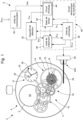
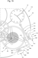
- the timepiece 2 comprises a mechanical movement 4, an analogue time display 12, a mechanism 10 for driving this display and a device 6 for correcting the actual time indicated by the display.
- the timepiece is a wristwatch conventionally comprising a case 220 and a crown 52 forming an external control member to allow manual setting of the display via an internal control stem secured to the crown.
- the mechanical time correction system acts on a minute wheel in direct engagement with a cannon pinion carrying the minute hand and an hour wheel carrying the hour hand.
- the hour and minute hands always maintain a kinematic link even during a time setting.
- the cannon-pinion undergoes friction relative to a wheel or a wheel of the drive mechanism and thus an angular displacement relative to the wheels of this drive mechanism located upstream, and therefore to the second wheel carrying the second hand.
- the second hand does not have a given phase relationship with the minute hand once a time setting via the stem-crown has taken place, that is to say that there is generally no determined temporal / angular relationship between the indication of the current minute and the indication of the current second.
- the second indicator When the indicator is precisely aligned with a minute graduation (which generally also serves as a second graduation when the minute and second hands are coaxial), the second indicator has a temporal / angular position that is arbitrary (any undetermined position). This fact concerns in particular timepieces equipped with a mechanical movement driving an analog display of the time.
- the mechanical movement comprises a barrel 8 forming a source of mechanical energy for the drive mechanism 10 which is formed by a gear train 11, kinematically linked to the display, a mechanical resonator 14, formed by a balance wheel 16 associated with a balance spring 15, and an escapement 18 coupling this resonator to the drive mechanism so that the oscillation of the mechanical resonator sets the rate of the running of this drive mechanism.
- the analog display 12 is formed by a dial 32, comprising indexes 36 forming a graduation for displaying the real time, and by hands 34 comprising an hour hand 34H giving the current hour, a minute hand 34M giving the current minute, and a second hand 34S giving the current second of the real time displayed.
- the hands generally have different shapes, in particular different lengths and/or widths.
- the present invention is not limited to an analogue display of the real time, but may also relate to other displays of the real time, for example a display with a 'jumping hour' and/or in particular a 'jumping minute'.
- the display is therefore not limited to a system with hands having a quasi-continuous advance.
- the invention may therefore also be applied in particular to a system with discs or rings and in particular to a display provided through at least one aperture machined in the dial.
- the timepiece 2 is arranged so as to allow a correction of the real time indicated by its display as a function of an overall time error for this display which is determined inside the timepiece by the electronic correction circuit 40 associated with the detection device 30, which is arranged to be able to detect the passage of the seconds hand 34S through at least a first reference time position of the display and the passage of the minutes indicator 34M through at least a second reference time position of this display.
- the device correction generally comprises a device for braking the mechanical resonator.
- the braking device is formed by an electromechanical actuator, for example an actuator of the piezoelectric type 22A.
- the braking device is controlled by a control unit 48 which transmits to it a control signal S Cmd to control its power supply circuit so as to temporally manage the application of a mechanical braking force on the mechanical resonator 14.
- the correction device is arranged so that the braking device can act, each time that an overall time error has been determined by the electronic correction circuit, on the mechanical resonator during a correction period to vary the operation of the drive mechanism so as to correct at least partly this overall time error.
- the actuator 22A comprises a braking member which is formed by a flexible blade 24, which has on two opposite surfaces (perpendicular to the plane of the Figure 1 ) respectively two piezoelectric layers which are each coated with a metal layer forming an electrode.
- the piezoelectric actuator comprises a power supply circuit 26 for applying a certain voltage between the two electrodes so as to apply an electric field across the two piezoelectric layers, which are arranged so as to bend the blade 24 towards the felloe 20 of the balance 14, when a voltage is applied between the two electrodes, so that the end portion of the blade, forming a movable braking pad, can press against the external circular surface of the felloe and thus exert a mechanical braking force on the mechanical resonator.
- the voltage can be variable, to vary the mechanical braking force and therefore the mechanical braking torque applied to the balance.
- Concerning the braking device reference may be made to the document WO 2018/177779 for various variants of arrangement of such a braking device in a mechanical watch movement.
- the braking device is formed by a blade actuated by a magnet-coil system.
- the balance comprises a central shaft which defines or carries a part other than the rim of the balance, for example a disk, defining a circular braking surface. In the latter case, a shoe of the braking member is arranged so as to exert pressure against this circular braking surface during the momentary application of a mechanical braking force.
- the first embodiment of the timepiece incorporates a first embodiment of the detection device, described below with reference to Figures 2 to 6 , which is distinguished by the fact that it allows direct detection of the passage of at least one indicator of the analog display 12, relative to a time unit of the real time, by at least one reference time position of this display which is relative to said time unit, this indicator being arranged to be able to be detected itself by the detection device.
- the description of the first embodiment of the timepiece 2 will be made essentially within the framework of the main embodiment, in which the detection device is arranged to be able to detect the passage of the seconds indicator by at least a first reference time position of the display and the passage of the minutes indicator by at least a second reference time position of this display, and in which the measurements for these two indicators are used in each correction cycle to perform a correction of the current minute and the current second of the real time displayed.
- a single detection unit is provided or two diametrically opposed detection units are provided.
- the variant shown advantageously provides the same detection units for detecting passages of the second hand and the minute hand. However, in another variant, different detection units can be provided for the two hands.
- the optical detection device comprises at least one light source, each capable of emitting a beam of light, and at least one photosensitive detector each capable of capturing light emitted by a light source of said at least one light source.
- the seconds indicator and the minutes indicator each have a reflection surface which passes through the beam(s) of light emitted by at least one light source when the indicator in question passes through at least one reference time position corresponding to this indicator and defined by the detection device, in particular opposite at least one detection unit of this detection device.
- the detection device and the reflection surface are configured such that this reflection surface can reflect, when the indicator in question passes through any reference time position of said at least one corresponding reference time position, incident light, provided by a light source of said at least one light source, at least partially in the direction of a photosensitive detector of said at least one photosensitive detector which is associated with said any reference time position.
- the reflection surface of each indicator considered is formed by a lower surface of this indicator, and said at least one light source and said at least one photosensitive detector are supported by a dial of the timepiece or housed at least partially in the dial, or located under the dial which is then arranged to allow the beam(s) of light to pass through it.
- the light emitted by said at least one light source is not visible to the human eye.
- the light source emits light in the infrared range in particular.
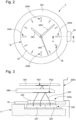
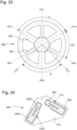
- FIG. 3 is a partial section of the watch of the Figure 2 , through the detection unit 224a of the optical detection device 30. It will be noted that the four detection units are similar.
- the watch case is represented by its internal profile 220a.
- the detection unit 224a comprises an optical sensor 226 formed by a light source 228, which emits a light beam 232, and a photosensitive detector 227 capable of capturing light emitted by the light source, the source and the detector being aligned in a radial direction relative to the central axis of the watch around which the second hand and the minute hand rotate.
- the optical sensor 226 is arranged under the dial 32 and supported by the plate of the mechanical movement 4.
- the dial has an opening in which is arranged a glass plate 230 which has on its lower surface a sawtooth profile forming two refraction gratings (series of parallel oblique planes) intended to refract respectively the light emitted by the source 228 and the light incident on the detector 227 after reflection by one or the other of the two hands 34M and 34S.
- the plate can be made of another substance which has sufficiently good transparency for the light emitted by the source 228, in particular for infrared light if necessary. It will be noted that the plate can also form an upper element of the sensor 226 and then be inserted into the opening of the dial during the assembly of the optical sensor with the dial.
- the optical detection unit 224a is remarkable because the electronic units forming the light source and the photosensitive detector are arranged on a common substrate in a general plane parallel to the dial 32 with the emitted light having a main direction (optical axis) which is perpendicular to this general plane, but the light beam 232 is oblique.
- An air layer between the wafer and the sensor 226 is an advantage for obtaining a fairly large deflection angle of the light relative to the vertical direction, i.e. perpendicular to the dial. Thanks to such an arrangement, although the light emitted by the source 228 has a vertical optical axis, the reflective zones RS1 and RS2 defined respectively by the two lower surfaces of the second hand 34S and the minute hand 34M are flat and horizontal.
- the detection device since the lower surfaces of traditional hands are flat and parallel to the dial, the detection device requires little intervention on the hands, or even no intervention for metal hands or hands with a metal coating.
- a polished surface in the zones RS1 and RS2 is an advantage. Note that the two hands 34M and 34S are shown, at Figure 3 , one above the other to aid in understanding the operation of the optical detection unit for each of the two hands; but the detection of the second hand is provided in the absence of the minute hand above the detection unit.
- FIGs 4A to 4D four specific variants for the light source of the optical detection units are shown.
- the light source 228a for example a diode of the LED type (acronym for 'Light-Emitting Diode') or a laser diode of the VCSEL type (acronym for 'Vertical-Cavity Surface-Emitting Laser'), is arranged obliquely on a support.
- This first variant has the disadvantage of considerably increasing the height of the device.
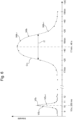
- the second variant a property of conventional laser diodes of the VCSEL type, non-collimated, is used, which naturally have a light intensity profile, shown in Figure 4B , with a maximum exhibiting an angular deviation relative to the perpendicular direction.
- the light beam 232 in a plane passing through its central axis, exhibits two symmetrical principal directions having an angular deviation ⁇ 0 .
- the light source 228c has on its emitting surface a diffraction structure RD which diffracts the light beam mainly in a given oblique direction.
- the fourth variant is similar to the variant of the Figure 3 .
- the light source 228d has on its emitting surface a transparent structure having its upper surface having a sawtooth profile which forms a refraction network RD (series of parallel oblique planes) intended to refract the light emitted by the source 228d. While the planes inclined to the Figure 3 have an angle of approximately 45°, the inclined planes of the refraction grating RD have a smaller angle relative to the horizontal direction (for example 35°), so as to have a refraction angle for the light beam 232 which allows it to pass through the transparent structure.
- RD series of parallel oblique planes
- Figures 5A and 5B Two variants, where a particular treatment of the lower surfaces of the needles concerned is accepted, are shown in Figures 5A and 5B . Note that these two variants can be complementary to the variants described above.
- the needle 34D has a reflective diffraction grating in an area of its lower surface which passes through the incident beam 232a (beam having a normal direction) as it passes over an optical detection unit.
- the needle 34R has a reflection grating in an area of its lower surface which passes through the incident beam 232a as it passes over an optical detection unit.
- the detection device comprises U detection units for the seconds indicator and Q detection units for the minutes indicator, some of these detection units being able to be common to both hands.
- the detection units In the variant shown, four detection units common to both indicators are provided.
- Four detection units for the minute indicator allow this indicator to be detected in a time interval of approximately 15 minutes.
- the detection device described above is of the optical type.
- the detection device may be of another type, in particular of the capacitive, magnetic or inductive type.
- a detection unit of the capacitive, magnetic or inductive type may be subjected to the same control as that described for an optical detection unit and the same processing of the measurements carried out may be provided within the framework of a correction cycle according to the present invention; which leads to the same correction of the actual time displayed.
- the electronic correction circuit is arranged to be able to determine, in association with the internal time base 42 and on the basis of measurement values of a plurality of measurement values, at least one first time of passage T X0 of the seconds indicator through any reference time position, named X0, among the reference time positions provided for this seconds indicator, this first passage instant being composed of at least one corresponding value of the current reference second X R , and at least one second passage instant T Y0 of the minutes indicator by any second reference time position, named Y0, among the reference time positions provided for this minutes indicator, this second passage instant being composed of at least one corresponding value of the current reference minute Y R .
- the seconds hand is detected by a detection unit of its passage through the reference time position X0
- the minutes hand is detected by a detection unit of its passage through the reference time position Y0.
- a plurality of measurements are carried out at a measuring frequency F Ms .
- Each measurement gives a measurement value and occurs at a specific measuring time.
- the measurements are carried out over short time intervals.
- the light source is periodically activated at the measuring frequency F Ms to generate a plurality of light pulses, and the photosensitive detector provides a plurality of corresponding light intensity values.
- the detection device is activated so as to perform a plurality of successive measurements at at least one measurement frequency which is determined by the clock circuit 44 of the internal time base 42, this clock circuit providing a periodic digital signal at the measurement frequency F Ms directly to the detection device or indirectly to this detection device via the control unit.
- the measurement frequency is variable and the correction device 6 is arranged to be able to detect the passage of the seconds indicator through the position reference time position X0 with a first measuring frequency FS Mes and the passage of the minute indicator through the reference time position Y0 with a second measuring frequency FM Mes which is lower than the first measuring frequency.
- the second hand may be substantially stationary during the measurements. If, for example, a mechanical resonator oscillating substantially at 4 Hz is taken and the measuring frequency for the second hand corresponds to 4 Hz or 8 Hz, it may be that all the measurements occur during the maintenance pulses of the mechanical resonator and therefore when the escape wheel and also the second wheel carrying the second hand are rotating.
- the first measuring frequency FS Mes has a value other than twice the set frequency F0c divided by a positive integer N, i.e. FS Mes ⁇ 2 F0c/N.
- the measuring frequency is determined by the mechanical resonator in association with the clock circuit.
- the device for correcting the actual displayed time then comprises a sensor associated with the mechanical resonator and arranged to be able to detect the passages of the oscillating resonator through its neutral position, corresponding to its position of minimum potential energy.
- the detection device is activated and controlled by the control unit associated with the internal time base to perform a plurality of successive measurements each following the detection of a passage of the mechanical resonator through its neutral position and after a certain time phase shift since this detection.
- this time phase shift is between T0c/8 and 3 T0c/8, where T0c is the set period which is equal to the inverse of the set frequency.
- the clock circuit 44 is arranged to provide the control unit with a periodic signal at a frequency equal to 8/T0c or close to this value.
- the sensor provides the control unit with a signal indicating when the mechanical resonator passes through its neutral position.
- the control unit activates the reception of the signal provided by the clock circuit at the frequency approximately equal to 8/T0c and counts two rising or falling edges in the periodic signal.
- the control unit triggers a measurement and therefore a light pulse. If desired, the time of each measurement can thus be determined. Since the clock circuit and the mechanical resonator are not synchronized, the time shift will be in the above-mentioned range of values.
- 4 Hz can easily be derived from the clock circuit 44 which is arranged to provide second ticks to the time base for the measurement of the real reference time.
- the frequency FM Ms is generated by a ten-count cyclic counter, incremented by the second ticks associated with the control unit.
- the first series of measurements gives a first series of intensity values VS n , n being a positive integer, to which corresponds a first series of measurement times TS n .
- the second series of measurements gives a second series of intensity values VM k , k being a positive integer, to which corresponds a second series of measurement times TM k .
- each measurement corresponds to a pair of values VS n and TS n , respectively VM k and TM k .
- the processing phase following the detection phase it is not intended to record the real reference time corresponding to each measurement during the detection phase, but it is intended to number or classify in chronological order the measurements of each series of measurements, and to establish a temporal link with the real reference time T Rf for each series of measurements.
- the periodic digital signal at the measurement frequency F Ms can also be supplied to the processing unit 46 which receives the measurement values via a signal S Ms supplied to it by the detection device, directly or via the control unit.
- the rank of the measurement value may be sufficient to determine the corresponding measurement instant.
- T Ms which is the inverse of the measurement frequency F Ms .
- the control unit or directly the processing unit stores the corresponding real reference time TS Rf,X for the seconds hand, respectively TM Rf,Y for the minutes hand, and if a number of periods of the periodic measurement signal is determined between the stored real reference time and a measurement of rank n, respectively of rank k, then the rank (or number) of each measurement corresponds to a determined real reference time.
- the control unit waits for a second top that defines an initial time for a series of measurements and as soon as it receives it, on the one hand it activates the detection device or it takes into consideration measurements occurring only since this initial instant, with the exception of this initial instant, and on the other hand it records the real reference time TS Rf,X , respectively TM Rf,0 .
- TS n n / FS Ms + TS Rf , 0
- n 1 à N
- TM k k / FM Ms + TM Rf , 0
- k 1 à K
- N and K are the numbers of measurements for the detection of the second hand and the minute hand respectively.
- the processing unit 46 performs processing of each series of measurements to determine the first time T X0 of the seconds indicator passing through the reference time position X0 and the second time T Y0 of the minutes indicator passing through the reference time position Y0.
- Various methods of processing measurement data can be used. As examples, we will cite the two examples related to the Figure 6 , and a simplified example.
- an algorithm determines a width, corresponding to a time interval IT, substantially at mid-height of a symmetrical convex curve C Fit adjusted to the series of measurement values VM k in order to be able to determine a mid-value of this width, this mid-value defining the time of passage T Y0 of the mid-longitudinal axis of the minute hand by the reference time position Y0, which is defined by the mid-radial axis of the detection unit concerned / by the radial alignment direction of the light source and the photosensitive detector.
- the time interval IT is a characteristic parameter of the indicator concerned which makes it possible to differentiate it from other indicators.
- the maximum light intensity detected is also a characteristic parameter of the indicator considered.
- the algorithm implemented in the processing unit advantageously uses the numbers / ranks k corresponding to the values VM k .
- the value T Y0 does not correspond to an entire rank/number (the measurements occurring here only every 10 seconds), but it corresponds to a fractional number Z F intermediate between two adjacent ranks/numbers.
- T Y0 therefore has an integer value PM Y0 in minutes (integer part of T Y0 ) corresponding to the current reference minute when the indicator passes through the reference time position Y0, to which is added a value PS Y0 in seconds which defines a fractional part for the minute current given by the minute indicator when the indicator passes through the reference time position Y0, this value PS Y0 corresponding to the current reference second when the minute indicator passes through the reference time position Y0.
- T Y0 ( PM Y0 ; PS Y0 ) .
- the value PS Y0 can possibly have decimals.
- the time of passage of the minute hand through a reference time position (which generally corresponds to an integer number of minutes) is generally determined with an integer part in minutes and a fractional part in seconds (sexagesimal part), this determination being preferably carried out with a precision of the order of a second or less than a second.
- control unit and/or the processing unit is/are connected to the internal time base so as to be able to store the real reference time at at least one given instant of the detection phase.
- the electronic correction circuit is arranged to be able to determine, during the detection phase, at least a first measurement instant and a second measurement instant corresponding respectively to at least a first measurement and a second measurement among a series of successive measurements, these first and second measurement instants being determined by the internal time base.
- the first measurement instant is composed of at least a first corresponding value of the current reference time unit and the second measurement instant is composed of at least a second value of this current reference time unit.
- the electronic correction circuit is arranged to be able to calculate, as a function of said at least one first measurement instant and a second measurement instant and the corresponding measurement values, a third instant which determines the time of passage of the indicator considered by the reference time position concerned.
- the time of passage of a needle through a reference time position is determined by comparing each measurement value received by the processing unit directly with a threshold value provided for this needle. As soon as the processing unit detects that the value of a measurement exceeds this threshold value, it assigns the time of this measurement to the time of passage and it records the value of the real reference time directly following this detection.
- This simplified variant is less precise, but it requires few electronic resources. The electronic correction circuit can therefore be simplified.
- the electronic correction circuit is arranged to be able to determine a first time error for the seconds indicator, by comparing at least a first passage time of this seconds indicator with a first corresponding reference time position, and a second time error for the minutes indicator by comparing at least a second passage time of this minutes indicator with a second corresponding reference time position.
- the determination of the first time error and the second time error is carried out by the processing unit which performs a subtraction between the determined passage time and the value of the corresponding reference time position.
- Es is given in seconds, possibly with one or more decimal places since T X0 is normally determined with decimal places (precision better than the second).
- the processing algorithm may decide to keep for example only one decimal place.
- T Y0 determined for the minutes indicator has an integer part PM Y0 in minutes and a fractional part PS Y0 in seconds
- the time error E M is determined with an integer part E Mm in minutes and a fractional part E Ms in seconds (E Ms is therefore added to E Mm ).
- E M (E Mm ; E Ms ) . It should be noted that E Ms can have one or more decimals resulting from the calculation carried out for its determination, but the algorithm generally does not keep a decimal for the value E Ms in seconds since this value is already a fractional part for the minutes indicator.
- the electronic correction circuit can also determine an overall time error T Err , for the display of a mechanical watch, as a function of the first time error determined for the seconds indicator, of the second time error determined for the minutes indicator, and of at least one predefined correction criterion which selects a manner of processing the first and second time errors to determine an overall time error for the display of the timepiece.
- the minute indicator among the set of indicators, is of the analog type, this minute indicator displaying a positive integer number of minutes and a fractional part that is variable.
- the timepiece further comprises a time-setting device that is arranged to momentarily break the kinematic connection between the minute indicator and the second indicator to perform a time-setting of said display.
- the electronic correction circuit is arranged to be able to determine an overall time error (T Err ) for the display as a function of at least one predefined correction criterion for the second indicator and/or the minute indicator in addition to the first and second time errors relating respectively to the second and minute indicators.
- the overall timing error is determined so as to substantially correct the first timing error for the seconds indicator during said correction period.
- the overall time error is determined so that the minute indicator has at the end of the correction period, for the case where this minute indicator then has a time shift corresponding to a delay, at most a maximum delay which is selected in the range of values of the fractional part of the current minute displayed, i.e. between zero and sixty seconds of delay.
- the determination of the overall time error T Err is carried out by the processing unit which then provides it to the control unit for the phase of correction of the time displayed by the timepiece.
- the overall time error can also be calculated by the control unit which then receives from the processing unit the time errors determined for the indicators considered.
- the correction signal S Cor provided by the processing unit comprises either the value T Err , or the values Es and E M .
- the processing unit and the control unit can advantageously be formed by a single electronic circuit or the same electronic unit. The distinction between these two units is functional, to better explain the various phases of a correction cycle.
- the overall correction of the watch display to be made during a correction cycle is given by -T Err converted entirely into seconds.
- -T Err converted entirely into seconds.
- example 1 we will correct by making an advance of 95 seconds
- example 2 we will correct by making an advance of 90 seconds
- example 3 we will correct by moving back 65 seconds in the actual time displayed.
- a correction device intended to correct the actual time displayed as a function of two time errors determined respectively for a second hand and a minute hand of a watch equipped with a mechanical movement, but the invention is not limited to this main embodiment. Indeed, in a particular embodiment, a time error is also determined for the hour hand and the correction provided is also as a function of this time error. For the hour hand which is normally in phase with the minute hand and continually in meshing relationship with this minute hand, only the difference between the current time displayed and a current reference time given by the time base is taken into account to determine the overall time error.
- the timepiece comprises only a current hour indicator and a current minute indicator (therefore no indication of the current second).
- only a time error is determined for the minute indicator.
- the overall time error is equal to the time error determined for the minute indicator.
- the timepiece further comprises a communication unit 50 which is arranged to receive from an external device, an external installation or an external system a synchronization signal S Sync providing an exact real time or an exact real time which is composed only of the exact current minute and the exact current second, given that in the main embodiment only the indicators of the seconds and minutes are detected and then corrected globally.
- the communication unit 50 provides the exact real time H RE or said exact real time to the internal time base 42 which then synchronizes the reference real time / the reference real time on the exact real time / this exact real time.
- the external synchronization system can be a GPS system which gives a legal time very precisely.
- the communication unit is formed by a unit for receiving a GPS signal relating to the exact real time.
- the external installation is a long-distance radio-synchronization antenna, as found in particular in Europe and the USA.
- the communication unit is formed by a unit for receiving an RF signal.
- the external device is a portable electronic device, for example a mobile phone or a computer.
- the communication unit comprises a BLE communication unit (acronym for 'Bluetooth Low Energy') or NFC (acronym for 'Near Field Communication').
- the exact real time or the exact real time is generally derived from the time base of the external device, which is normally regularly synchronized to a clock giving the exact legal time via the telephone network or via the Internet network.
- the correction device comprises a wireless communication unit which is arranged to be able to communicate with an external system capable of providing the exact real time, the correction device being arranged to be able to synchronize the reference real time on an exact real time, composed of current time units of the exact real time corresponding to those of the reference real time, during a synchronization phase during which the communication unit is activated so as to receive from the external system the exact real time or said exact real time.
- the communication unit is activated periodically by the control unit or directly by the internal time base to receive the exact real time or the exact real time.
- the communication unit is activated periodically and automatically, to perform a synchronization of the reference real time on the exact real time during a synchronization phase.
- the user can activate the communication unit in particular via an external control member of the timepiece. The two variants can be combined to have an automatic periodic synchronization and the possibility of performing a synchronization on demand.
- the communication unit is particularly important following a power failure of the internal time base.
- the control unit is arranged so as not to perform any correction cycle if the real reference time has not been synchronized with an external system providing the exact real time and maintained by the circuit internal clock continuously since a last synchronization phase.
- this information is recorded in a permanent memory (non-volatile memory) which comprises at least one status bit ('ON'/'OFF') for the internal time base.
- the status bit Upon subsequent reactivation of the time base, the status bit retains its value 'OFF' until the correction device synchronizes the time base to the exact real time of an external system, as disclosed.
- the control unit Before performing a correction cycle, in particular before performing a detection phase, the control unit interrogates the status bit to know its value, and does not perform any detection phase as long as this value is 'OFF'. Only when the value of the status bit is 'ON', the correction device then starts a new correction cycle with a detection phase. If a cycle is interrupted and it is intended to continue it, in particular following a possible interruption of a correction cycle between the processing phase and the correction phase, the control unit may subsequently continue such a correction cycle provided that the previous detection phase has been completed correctly and the actual reference time is no longer useful for continuing the correction cycle.
- the timepiece comprises an external control member for synchronizing the real reference time with the exact real time, this external control member being operable by a user of the timepiece.
- the external control member and the correction device are arranged so as to allow a user to activate the correction device so that this correction device performs a synchronization of the real reference time with the exact real time during a synchronization phase.
- the external control member is formed by a crown associated with a control stem which also serve to manually set the time of the display.
- a watch having a mechanical movement conventionally comprises a manual time-setting device via a stem-crown.
- a manual time-setting with the exception of a manual control provided for making the hour hand jump by one hour, a manual control which is moreover advantageous for the timepiece according to the invention, in particular for the main embodiment described above.
- a mechanism can be provided to block the external control member (the stem-crown) so that it cannot modify the position of the minute hand and/or stop the second hand during a correction cycle. This normally requires an electromechanical actuator, which makes the timepiece more complex.
- An alternative is to provide detection of the movements of the stem-crown, in particular to detect whether this control member is moved to a position corresponding to the time setting with the possibility of modifying the position of the minute hand and/or the second hand. As soon as such detection occurs, the control unit ends the correction cycle in progress. Furthermore, before starting a correction cycle, the correction device detects whether the control member is in the aforementioned manual correction position and the control unit does not start a correction cycle if this is the case and as long as this situation persists.
- the device for detecting whether the stem is in the time setting position can be easily arranged along the control stem or the time setting mechanism associated with this stem. It is advantageous to opt for capacitive or magnetic detection (by placing a small magnet on the stem or on the associated mechanism).
- each time the correction device detects that the external control member has been moved into its time-setting position it quickly performs a correction cycle as soon as this member is then replaced in another position (notably the winding position for a stem-crown).
- the timepiece comprises an energy harvester 54 which can be formed by various types of devices known to those skilled in the art, in particular a magnetic, light or heat energy harvester, as well as an electricity accumulator 56.
- the magnetic energy harvester is arranged to receive energy from an external magnetic source for recharging the electricity accumulator 56 without electrical contact.
- the energy harvester is formed by a magnet-coil system for recovering a little energy from the oscillation of the mechanical resonator of the timepiece and therefore from the barrel maintaining this oscillation.
- At least one magnet is arranged on the oscillating element of the resonator or on the support of the resonator and at least one coil respectively on said support or on said oscillating element, such that the majority of the magnetic flux generated by the magnet passes through the coil when the resonator oscillates in its useful operating range.
- the magnet-coil coupling is provided around the neutral position (rest position) of the resonator.
- the oscillating mass is used to drive a micro-generator producing an electric current which is stored in the accumulator.
- the energy harvester can also be hybrid, i.e. formed of several different units, in particular of the wireless/contactless type, which are provided to harvest various energies from various energy sources and transform these various energies into electrical energy.
- the timepiece can begin a required correction operation if the electrical voltage available is sufficient and perform this correction operation as long as the electrical voltage provided by the power supply circuit 58 is sufficient.
- Various parts of the correction module can be activated, as required, only during different periods.
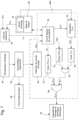
- the control unit 48A of the timepiece 2 comprises a logic control circuit 60 connected to the time base 42 and to the processing unit 46 which provides it, as a correction signal S Cor , with the value of the overall time error T Err determined during the previous processing phase.
- the logic control circuit is arranged to perform various logic operations during each correction cycle.
- the control unit 48A comprises a generator device 62 of a periodic digital signal having a given frequency F SUP (the generator device 62 is also called a 'frequency generator' or simply a 'generator' at the frequency F SUP ).
- the logic control circuit 60 Depending on whether the overall time error T Err to be corrected corresponds to a delay (negative T Err ) or an advance (positive T Err ) in the display of the real time, the logic control circuit 60 generates respectively either two control signals S1 R and S2 R , which it supplies respectively to the frequency generator 62 and to a time counter 63 ('timer'), or a control signal S A which it supplies to a time counter 70.
- the time counters 63 and 70 are programmable and are used to measure a planned correction period, respectively a period PR Cor for the correction of a delay and a period PA Cor for the correction of an advance.
- an advance corresponds to a positive error and a delay corresponds to a negative error.
- control unit 48A for correcting a detected delay in the time display during a correction phase following the detection and processing phases described above will be explained below first, and subsequently the arrangement of this unit for correcting an advance during a correction phase.
- the logic control circuit 60 activates the frequency generator 62 via the signal S1 R and the time counter 63 which counts up or down a time interval corresponding to a correction period PR Cor whose duration (the value) is determined by the logic circuit (by definition, the expression 'time counter' includes a time counter at a given time interval and also a time downcounter to zero from this given time interval which is initially introduced into this time downcounter).
- the frequency generator when the frequency generator is activated, it supplies a periodic digital signal S FS , at the frequency F SUP , to another time counter 64 (timer at a value Tp corresponding to a duration selected for the periodic braking pulses).
- the outputs timers 63 and 64 are provided to an 'AND' logic gate 65 which outputs a periodic activation signal S C1 to periodically activate the braking device 22, during the intended correction period PR Cor , via an 'OR' logic gate 66 or any other switching circuit for transmitting the periodic activation signal S C1 to the braking device.
- the periodic activation signal S C1 forms the control signal S Cmd in the case of a correction of a delay detected in the time displayed by the timepiece.
- the braking device applies periodic braking pulses to the mechanical resonator at the frequency F SUP during a correction period PR Cor whose duration (value) depends on the delay to be corrected.
- the braking pulses have a dissipative nature because part of the energy of the oscillating resonator is dissipated during these braking pulses.
- the mechanical braking torque is applied substantially by friction, in particular by means of a mechanical braking member exerting a certain pressure on a braking surface of the resonator, preferably a circular braking surface, as previously explained during the description of the timepiece 2 with reference to the Figure 1 .
- the system formed by the mechanical resonator and the braking device of this resonator is configured so as to allow the braking device to start, in the useful operating range of the oscillating resonator, a mechanical braking pulse substantially at any instant of the natural oscillation period of the oscillating resonator.
- one of the periodic braking pulses can start substantially at any angular position of the oscillating resonator, in particular the first braking pulse occurring during a correction period.
- the braking frequency F FR is proportional to the set frequency F0c for the mechanical resonator and depends only on this set frequency as soon as the positive integer N is given.
- the present invention proposes to use this remarkable discovery to carry out a correction of the time displayed by a timepiece by varying the rate of the mechanical watch movement considered, that is to say by varying the frequency of the resonator which sets the rate of the drive mechanism of the display of the timepiece in question during a given correction period.
- the periodic braking pulses are applied to the mechanical resonator at a braking frequency F Bra advantageously corresponding to twice the correction frequency F Cor divided by a positive integer N, preferably low.
- the braking frequency F Bra is therefore proportional to the intended correction frequency F Cor and depends only on this correction frequency as soon as the positive integer N is selected.
- 'synchronization on a given frequency' is meant an average synchronization on this given frequency. This definition is important for a number N greater than two.
- the braking pulses can be applied with a constant torque or a non-constant torque (for example, substantially in a Gaussian or sinusoidal curve).
- 'braking pulse' is meant the momentary application of a torque to the resonator which brakes its oscillating member (balance), i.e. which opposes the oscillation movement of this oscillating member.
- the duration of the pulse is generally defined as the part of this pulse which presents a significant torque to brake the resonator, in particular the part for which the torque is greater than half the maximum value.
- a braking pulse can present a large variation. It can even be chopped and form a succession of shorter pulses.
- the duration of each braking pulse is expected to be less than half of a setpoint period T0c for the resonator, but it is advantageously less than a quarter of a setpoint period and preferably less than T0c/8.
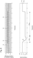
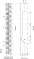
- the graphs below the Figures 8 , 9 show the evolution of the oscillation frequency of the resonator during a correction period, which is defined as the period during which the braking pulses at the frequency F INF or F SUP are applied to the resonator.
- Curve 78 shows the evolution of the oscillation frequency of the mechanical resonator during the application of the first series of periodic braking pulses 74 for a correction of an advance detected in the displayed time, the braking frequency F INF leading to a correction frequency FI Cor , given by the synchronization frequency, which is lower than the set frequency F0c (first mode of correction of an advance).
- Curve 80 shows the evolution of the oscillation frequency of the mechanical resonator during the application of the second series of periodic braking pulses 76 for a correction of a delay detected in the displayed time, the braking frequency F SUP leading to a correction frequency FS Cor , given by the synchronization frequency, which is higher than the set frequency (first mode of correction of a delay).
- the correction frequencies are given purely as examples and are much closer to the set frequency than the correction frequencies which are generally provided for the implementation of the first mode of correction of an advance or retardation.
- the Figures 8 And 9 are given only schematically to generally explain the behavior of the oscillating resonator when subjected to a series of periodic braking pulses at a correction frequency close to the set frequency, but different from it, and in the case of a natural frequency leading to a classical time drift. More detailed and precise considerations regarding possible correction frequencies will be explained later.
- a transient phase PH Tr is observed at the beginning of the correction period during which the frequency varies before stabilizing at the frequency FI Cor , respectively FS Cor during a synchronous phase PH Syn which follows the transient phase.
- the transient phase PH Tr is relatively short (less than 2 seconds) and the frequency changes in the direction of the desired correction frequency.
- the average correction per unit time during the transient phase is approximately equal to that which occurs during the synchronous phase.
- the transient phase can be longer, for example from 3 to 10 seconds, and the frequency change during the transient phase varies from case to case so that the average correction is variable and not determined, but it remains practically small.
- the correction period PR Cor is determined (the duration of) only on the basis of the overall time error T Err to be corrected, by defining this correction period as the period during which a series of periodic braking pulses are applied to the resonator at the intended braking frequency, and by assuming that the oscillation frequency during the correction period is that of the synchronization frequency.
- the synchronization frequency determines the correction frequency.
- the correction frequency F Cor is equal to the synchronization frequency. It should be noted that, in the synchronous phase of the correction period, the duration of the braking pulses must be sufficient for the braking torque applied to the resonator to allow it to stop. (passage through an extreme angular position, defining its instantaneous amplitude) during or at the end of each braking pulse.
- the time interval during which the resonator remains stopped during a braking pulse reduces the possible correction per unit of time, so that it is preferable to limit this time interval, taking into account a certain safety margin, to have a shorter correction period thanks to a higher synchronization frequency.
- the frequency of the braking pulses, the maintenance energy supplied to the resonator at each alternation of its oscillation and the value of the braking torque intervene in the time interval necessary to stop the oscillating resonator.
- a braking torque and a duration for the braking pulses so as to optimize the braking system.
- braking torques between 0.5 ⁇ Nm and 50 ⁇ Nm and braking pulse durations between 2 ms and 10 ms are generally suitable for correction frequencies that are practically advantageous to use (these value ranges are given as examples and are not intended to be limiting).
- the value of the correction period to be expected can be determined on the basis of the overall time error T Err to be corrected, the set frequency F0c and the correction frequency F Cor ; and since the synchronization frequency determines the correction frequency which is equal to it, the value of the correction period to be expected can also be determined on the basis of the overall time error T Err to be corrected, the set frequency F0c and the braking frequency F Bra .
- an advance in the time display corresponds to a positive error while a delay corresponds to a negative error.
- the control unit 48A ( Figure 7 ) is arranged to provide the braking device, each time the overall time error T Err corresponds to a delay in the displayed time that is intended to be corrected, with a control signal S C1 derived from the periodic digital signal S FS provided by the frequency generator 62, during a correction period PR Cor , to activate the braking device 22 so that this braking device generates a series of periodic braking pulses which are applied to the resonator at the frequency F SUP .
- the frequency F SUP is provided and the braking device is arranged such that each series of periodic braking pulses at the frequency F SUP can generate, during the corresponding correction period, a first synchronous phase in which the oscillation of the resonator is synchronized (by definition 'synchronized on average') on a correction frequency FScor which is higher than the set frequency F0c provided for the mechanical resonator.
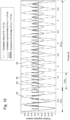
- a demonstrator (a prototype of the timepiece according to the invention) was produced for the case presented in the Figure 10 .
- Such a result opens up prospects for corrections of the time indicated by the display which are other than corrections of a time drift of this display due solely to the inaccuracy of the resonator operating freely (i.e. in the absence of braking pulses).
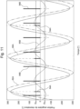
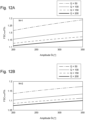
- FIG. 11 shows the free oscillation 82A of a mechanical resonator, a first oscillation 86A of this resonator in a synchronous phase of a correction period where the ratio RS between the correction frequency FS Cor and the set frequency F0c is relatively low (i.e. relatively close to '1'), and a second oscillation 86B of this resonator in a synchronous phase of a correction period where the ratio RS between the correction frequency FScor and the set frequency F0c is relatively high (i.e. relatively far from '1').
- the correction frequency can vary continuously between the set frequency F0c and a certain higher frequency FSC max , for the correction of a delay in the displayed time, and continuously between the set frequency F0c and a certain lower frequency FIC max , for the correction of an advance in the displayed time.
- the upper frequency FSC max and the lower frequency FIC max are not values that can be easily calculated theoretically. They must be determined practically for each timepiece. It will be noted that although this information is interesting, it is not necessary.
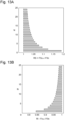
- the braking frequencies are selected and the braking torques available are suitable to generate during each correction period, preferably fairly quickly, a synchronous phase during which the mechanical resonator can oscillate at the correction frequency provided by the mathematical relationship given above, without being stopped in its oscillation (i.e. it is necessary to avoid stopping the resonator so that it can no longer start again from the stop position, which would lead to a stoppage of the display drive mechanism).
- a safety angle ⁇ Sec is indicated below which, in absolute value, stopping of the mechanical resonator will be avoided (i.e. between - ⁇ Sec and ⁇ Sec ), and therefore above which the amplitude, in absolute value, must practically remain during the synchronous phase, at least after the stabilization phase.
- the angle ⁇ Sec is provided equal to or, preferably, greater than an angle ⁇ ZI (see Figure 14 ) which corresponds to the coupling angle between the resonator and the escapement associated with it, on one side and on the other side of the neutral position of the resonator defined by the angular position of the coupling pin carried by the balance wheel plate when this resonator is at or passes through its rest position.
- the person skilled in the art will be able to determine a value for the safety angle ⁇ Sec for each mechanical movement associated with a correction device according to the first embodiment.
- the coupling angle ⁇ ZI may vary from one mechanical movement to another, in particular between 22° and 28°.
- said condition of non-blocking of the resonator in the safety angular zone during the correction period of a delay is important because a counting of the flow of time via the escapement (i.e. the timing of the running of the drive mechanism of the time display) must continue during this correction period of a delay.
- said frequency F SUP and the duration of the periodic braking pulses are selected such that, during said synchronous phase of a correction period within the framework of the first mode of correction of a delay, the periodic braking pulses each occur outside a coupling zone between the oscillating mechanical resonator and the escapement, preferably outside a safety zone defined for the mechanical movement.
- the selection of said frequency F INF and the duration of the periodic braking pulses within the framework of the first mode of correction of an advance.
- ⁇ t ⁇ 0 + ⁇ Sec ⁇ ⁇ 0 e ⁇ t ⁇ ⁇ cos 2 ⁇ f 0 t
- ⁇ Q ⁇ T0 / ⁇
- ⁇ 0 the amplitude of the free oscillation.
- T Sec ⁇ 1 N ⁇ Secitational T Sec ⁇ 2 N ⁇ 1 4 T 0 , N 2 T 0
- T Sec ⁇ 1 N ⁇ Secitati ⁇ T Sec ⁇ N 2 T 0 , 2 N + 1 4 T 0
- the timepiece comprises a device for blocking the mechanical resonator.
- the control unit is arranged to be able to provide the blocking device, when the external correction signal received by the reception unit corresponds to an advance in the displayed time that it is intended to correct, a control signal which activates the blocking device such that this blocking device blocks the oscillation of the mechanical resonator during a correction period whose value/duration is determined by the advance to be corrected, so as to stop the operation of said drive mechanism during this correction period.
- the timepiece 2 comprises a blocking device which is constituted by the braking device 22, in particular by the piezoelectric actuator 22A, which also serves to implement the first mode of correction of a delay.
- the logic circuit 60 of the control unit 48A ( Figure 7 ) provides a control signal S A to the time counter 70 (timer) which is programmable.
- This timer 70 then generates a signal S C2 for activating the braking device 22, via the 'OR' gate 66 or another switch, for a correction period PA Cor whose duration is substantially equal to the corresponding advance T Err to be corrected.
- the periodic activation signal S C2 then forms the control signal S Cmd .
- the voltage then supplied by the power supply circuit 26 between the two electrodes of the piezoelectric blade 24 may differ from that intended to generate the periodic braking pulses to correct a delay. This voltage is selected so that the braking force applied to the mechanical resonator can stop it, preferably fairly quickly, and then block it until the end of the correction period.
- the electrical voltage applied to the piezoelectric blade 24 is provided to be variable during the correction period. For example, it is possible to provide a higher voltage at the start of the correction period, which is selected to quickly stop the resonator, in particular during the alternation of the oscillation of this resonator in which the start of the correction period occurs, and then to reduce the voltage to a lower value but sufficient to keep the resonator stopped.
- the electrical voltage will be selected so that the resulting braking force cannot stop the mechanical resonator in the forbidden angular zone (- ⁇ ZI to ⁇ ZI ) defined above.
- the braking torque is selected large enough to be able to stop the resonator and block it in the angular stopping position, whatever it may be, and small enough so that this braking torque cannot stop the resonator in the forbidden angular zone.
- one will avoid stopping the resonator in the safety angular zone (- ⁇ Sec to ⁇ Sec ), described above. This last condition is important when the resonator is not self-starting. Generally speaking, it is sufficient to ensure that the resonator can start up again at the end of the correction period.
- a preliminary phase is provided occurring before the correction period where the resonator is blocked (i.e. where it remains stopped following its stopping occurring rapidly or immediately at the start of the correction period).
- the preliminary phase it is provided to use the first mode of correction of a delay available in the first embodiment. It can be seen that in the synchronous phase of the first correction mode described above, the passage through an extreme angular position occurs during each braking pulse.
- the braking pulses are in phase with passages of the mechanical resonator through one of its two extreme angular positions, each of these passages defining the start of an alternation.
- the frequency generator 62 activates the frequency generator 62 during the preliminary phase, which is provided to be relatively short in duration but nevertheless of sufficient duration to establish a synchronous phase where the resonator is synchronized to the frequency FS Cor .
- the preliminary phase ends for example with a final braking pulse which is immediately followed by the correction period with an activation of the braking device in the blocking mode.
- the braking torque for the preliminary phase may be planned to be different from that used for the correction of a delay described above.
- This mechanical movement 92 comprises a conventional escapement 94 formed by an anchor wheel 95 and an anchor 96 capable of oscillating between two pins 95.
- the anchor comprises a fork 97 between the horns of which the pin 98 also forming the escapement and carried by a plate 100 which is integral with the shaft 102 of the balance 104 (partially shown) of the mechanical resonator or made of the same material as this shaft (i.e. the shaft is machined with a longitudinal profile defining the plate).
- the plate 100 is circular and centered on the central axis of the shaft 102 which defines the axis of rotation of the balance wheel 104.
- the timepiece includes a blocking device 106 which is distinct from the braking device 22A ( Figure 1 ) used for the correction of a delay.
- This blocking device is therefore dedicated to the implementation of the second mode of correction of an advance.
- the blocking device is formed by an electromechanical actuator, in particular by a piezoelectric actuator of the same type described in connection with the Figure 1 .
- the actuator comprises a flexible piezoelectric blade 24A and its two electrodes are supplied with voltage by a power supply circuit 26A.
- the blade 24A has at its free end a projecting part 107, forming a stud, which is located on the side of the plate 100.
- the blade extends in a direction parallel to a tangent of the circumference of the plate, at a short distance from this circular circumference.
- the plate has a through hollow 108, which opens radially on the periphery of the plate and whose profile in the general plane of the plate is provided to allow the stud 107 to be housed there when it is located angularly opposite this hollow and the piezoelectric actuator 106 is activated.
- the hollow 108 is diametrically opposite the pin 98 and the stud is located angularly at the zero position of the pin (i.e. at the angular position of this pin when the resonator is at rest, respectively passes through its neutral position).
- this zero angular position of the pin normally defines the zero angular position of the balance 104, and therefore of the mechanical resonator, in an angular reference frame fixed relative to the mechanical movement 92 and centered on the axis of rotation of the balance.
- the hollow may be arranged at another angle relative to the pin, for example at 90°, and the actuator 106 is then positioned at the periphery of the plate so that the stud 107 is diametrically opposite the hollow when the resonator is at rest.
- the stud will enter the hollow when the resonator is in an angular position equal, in absolute value, approximately 180° (this being exactly the case if the balance is set to the reference mark, i.e. the pin is aligned with the respective centres of rotation of the balance and the anchor when the resonator is at rest).
- This value of 180° is clearly outside the safety zone (it is greater than the safety angle defined previously) and it is generally less than the range of amplitudes of the mechanical resonator corresponding to its useful operating range.
- the side walls of the hollow 108 are parallel to the radius passing through its center and the axis of rotation of the balance.
- these side walls are provided radial.
- the stud 107 has two side walls, perpendicular to the general plane of the plate, which are parallel to the radius passing through its center and the axis of rotation of the balance or which are, in the equivalent variant, substantially radial relative to the axis of rotation.
- this stud blocks the rotation of the plate 100 and therefore of the balance 104 by a substantially tangential force whose direction is substantially parallel to the general longitudinal direction of the piezoelectric blade 24A.
- the actuator 106 is activated, the end of the blade carrying the stud 107 undergoes a substantially radial displacement, relative to the axis of rotation of the balance, and the stud can then, depending on the angular position of the balance at that moment, either exert an essentially radial force on the circular lateral surface of the plate 100, or enter at least partially into the hollow 108.
- the actuator only needs to be arranged so that the stud can undergo, when this actuator is activated, a sufficient displacement to enter the hollow when the latter is located in an angular position corresponding substantially to that of the stud (in a fixed angular reference frame relative to the stud).
- a relatively low friction force can be expected when the stud comes to bear against the circular lateral surface of the plate at the beginning of a correction period, i.e. following activation of the actuator, in the case where the hollow is not opposite the stud when its proximal surface reaches the level of the circular circumference of the plate.
- the amplitude of the resonator decreases little during the initial braking carried out by the stud exerting a radial force against this circular lateral surface.
- the radial force exerted by the piezoelectric blade on the plate can be very low, or even zero.
- the electrical energy required to block the resonator during the correction period can therefore be relatively small, much smaller than in the case of the first embodiment.
- the correction device of the timepiece determines during a correction cycle an overall time error corresponding to an advance in the time display
- its logic control circuit in a manner similar to the operation of the first embodiment, activates the blocking device 106, by providing it with a control signal S C2 similar to that described previously in the context of the first embodiment, for a period substantially equal to the overall time error to be corrected.
- the start of the activation of the blocking device 106 can take place at any time, whatever the angular position of the resonator and whatever the direction of the oscillation movement (therefore independently of the alternation in progress among the two alternations forming each oscillation period). This is very advantageous.
- the electromechanical actuator may be of a type other than that shown in the Figure 10 .
- the actuator may comprise a ferromagnetic or magnetized core that can be moved under the action of a magnetic field generated by a coil.
- this core is colinear with the coil and it comprises an end portion exiting the coil at least when the actuator is activated, this end portion forming a finger that is configured to be able to be inserted into the hollow of the plate, this finger having in particular an end portion with the shape of the stud 107.
- the actuator is a bistable actuator.
- the power supply to the actuator is advantageously maintained, when it is activated to move from the non-interaction position to the interaction position, until the stud has entered at least partially into the hollow 108.
- Such a variant is particularly interesting because the actuator must not exert any blocking force by applying radial pressure to an element of the resonator balance in its two stable positions corresponding respectively to the intended non-interaction position and interaction position.
- the energy consumption can be very low, regardless of the duration of the correction period, which is very advantageous.
- the timepiece 112 according to the third embodiment comprises a blocking device 114 which is distinct from the braking device 22B used for correcting a delay.
- the braking device 22B has a operation which is similar to the braking device 22A already described, that is to say it is also suitable for the implementation of the first mode of correction of a delay explained in detail previously.
- the braking device 22B is formed by an electromechanical actuator of the electromagnetic type, that is to say comprising a magnet-coil system for actuating a flexible blade 240 embedded in a support 242 and the free end of which forms a braking element/shoe for the resonator 14.
- This actuator comprises a magnet 244, carried by the flexible blade, and a coil 246 located opposite the magnet and connected to a power supply 26B which receives the control signal S C1 , which generates electric current pulses in the coil to generate braking pulses.
- Each current pulse in the coil generates a magnetic flux which generates a magnetic repulsion force on the magnet 244, and the flexible blade 240 then comes into contact with the lateral surface of the rim 20 of the resonator to generate a certain mechanical braking force on this resonator during a braking pulse.
- the blocking device 114 is remarkable for at least two reasons. First, it acts on a conventional mechanical resonator 14 requiring no modification, in particular no specific machining unlike the second embodiment. Then, the blocking device is a bistable device, that is to say that a blocking element has two stable positions, namely here the lever 115. The blocking device is arranged such that a first of the two stable positions of the lever corresponds to a position of non-interaction with the balance 16 while the second of these two stable positions corresponds to a position of blocking of the resonator via a radial force exerted by a blade 116, forming the lever 115, on the rim 20 of the balance.
- the blade 116 is pivoted about an axis arranged in the mechanical movement 4A (in another variant, the lever is arranged so that its pivot axis is arranged on a support separate from the mechanical movement and belonging to a correction module). In one variant, this axis is formed by a fixed pin around which is mounted an annular terminal part of the blade 116. This blade is rigid or semi-rigid, a slight flexibility being able to be advantageous.
- the blade 116 is associated with a particular magnetic system making it possible to generate the bistable nature of the rocker 115 and consequently of the blocking device 114.
- the magnetic system comprises a first magnet 118, carried by the blade and therefore integral in rotation with this blade, a second magnet 119 arranged fixedly relative to the mechanical movement (in the variant shown, the second magnet is inserted fixedly in a lateral opening of the support 242) and a ferromagnetic plate 120 arranged between the first magnet and the second magnet, at a short distance from the second magnet 119 or against it (for example the plate is glued against this magnet, only a layer of glue then separating the magnet from the plate, or it is inserted fixedly in a housing of the support 242 located in front of the magnet 119).
- the first and second magnets 118, 119 have magnetic polarities that are opposite and their respective magnetic axes are substantially aligned.
- these two magnets would constantly exert a repulsive force on each other and the rocker would always remain or return, in the absence of forces external to the magnetic system, to a position where the blade is in abutment against a pin 124 limiting its rotation.
- the lever 115 is arranged so as to have two stable positions in the absence of forces external to the magnetic system of the locking device.
- the first stable position is a non-interaction position in which the blade 116 is in abutment against the pin 124, the movable magnet 118 then undergoing a magnetic repulsion force from the magnetic assembly, formed by the fixed magnet 119 and the ferromagnetic plate 120, which holds the lever 115 against this pin.
- the second stable position is an interaction position in which the blade 116 is in abutment against the felloe 20 of the balance 16, the movable magnet 118 then undergoing a magnetic attraction force from said magnetic assembly which holds the lever 115 against this felloe.
- the ferromagnetic plate 120 is arranged so that the blade 116 exerts a radial force for blocking the balance 16, and therefore the resonator 14, when the rocker is in its second stable position.
- the surface of the plate 120 located opposite the moving magnet 118, must be slightly set back relative to the proximal surface of this moving magnet when the blade 116 comes into contact with the felloe. If the blade is semi-rigid and therefore has a certain flexibility, it is possible that the moving magnet finally comes into abutment against the proximal surface of the ferromagnetic plate, but then the blade is in bending.
- the blocking device comprises an actuating device for this flip-flop arranged to alternately switch the flip-flop between its two stable positions.
- the actuating device is formed by a coil 252 connected to a power supply 254.
- the coil 252 is aligned with the magnetic assembly, formed by the fixed magnet 119 and the ferromagnetic plate. 120, and arranged just behind the movable magnet 118 when the rocker is in its non-interacting position.
- the movable magnet undergoes a magnetic attraction or repulsion force from this coil, thus making it possible to move the rocker from one of its two stable positions to the other in both directions.
- the actuating device is controlled by the logic circuit of the control unit via its power supply circuit 254 which receives the control signal S C2 .
- the control signal At the beginning of a correction period of an advance, the control signal generates a first pulse of electric current in the coil 252 with a polarity which generates a repulsive force for the movable magnet 118 and a duration sufficient for the rocker to switch to its interaction position, then the power supply to the coil is cut off until the end of the correction period when a second pulse of electric current is generated in the coil with an opposite polarity, this second pulse then generating an attractive force on the movable magnet which is expected to be sufficient to switch the rocker to its non-interaction position, thus ending the correction period.
- the actuating device of the rocker is provided separate and independent from the magnetic system of the bistable rocker.
- the electromagnetic system of the actuating device is formed by a second magnet carried by the rocker and a coil arranged opposite this second magnet, as in the previous variant. This electromagnetic system can be arranged upstream or downstream of said magnetic system relative to the pivot axis of the rocker.
- the blocking force exerted by the blocking device during the correction period does not come from an electrical supply of this blocking device, but from said magnetic system which forms it.
- the blocking device requires electrical power only at the beginning and at the end of the correction period occurring in the second correction mode. of an advance, when switching the flip-flop between its two stable states by the actuating device.
- the ferromagnetic plate 120 is arranged against the mobile magnet 118, to which it is integral.
- the blade of the rocker comprises, in the region of contact with the felloe 20, a stud which projects towards this felloe, which has a hollow along its generally circular circumference.
- the locking device so that its first stable position is a non-interaction position and its second stable position is an interaction position in which the stud is at least partially inserted into the hollow, this stud generally initially exerting a dynamic dry friction against the external lateral surface of the felloe, when the lever is actuated by the actuating device to pass from its first stable position to its second stable position at the start of a period of correction of an advance, before entering the hollow when the latter is presented opposite the stud during the oscillation of the balance.
- This fourth embodiment is a preferred embodiment which differs from the first embodiment substantially by its method of correcting an advance.
- the power supply 130 of the correction device 132 comprises an energy harvester formed by a solar cell 54A, in particular arranged at the level of the dial or the bezel carrying the glass protecting the dial. This dial generally forms a part of the time display.
- an external control device 136 is provided to be able to provide an activation signal on demand to the correction device, by a user of the timepiece, to trigger/start in the timepiece a cycle of correction of the displayed time (in other words to launch the method of correction of the displayed time which is implemented in the correction device 132).
- the power supply 130 comprises a circuit 134 for managing the power supply of the correction device 132.
- This circuit is capable of receiving various information from the electricity accumulator 56 and it receives from the external control device 136 a wake-up signal S W-UP when this device is actuated by a user.
- the management circuit 134 detects the level of energy available in the accumulator 56.
- the management circuit can react in various ways. In particular, it can either remain on standby for a supply of electrical energy via its solar cell or another energy recovery means provided in addition, or start a correction cycle as far as possible while knowing that it risks not being able to complete it correctly due to a lack of available energy.
- the correction device already directly performs such a detection phase by supplying only the parts necessary for this detection phase, while waiting for a new supply of electrical energy to be able to then perform a correction phase.
- the management circuit 134 activates the correction device to perform a correction cycle.
- any correction provided here is carried out by a series of periodic braking pulses during a correction period.
- all the braking pulses are provided with the same duration Tp.
- this timer 64 is arranged, in the variant shown in Figure 16 , in the power supply circuit 26C.
- This timer provides an activation/actuation signal S Act to a switch 138 placed between a voltage source 140 and the braking member 24C acting on the balance.
- the braking member 24C is for example similar to the piezoelectric blade ( Figure 1 ) of the variant shown for the first embodiment or to the flexible blade associated with the magnet-coil system ( Figure 15 ) of the third embodiment.
- the switch 138 controls the power supply of the actuator forming the braking device.
- the timer 64 receives a first control signal S1 Cmd from a switching device 66A which is controlled by the logic circuit 60A so that the first control signal is selectively formed by a periodic digital signal among three periodic digital signals provided S FS , S FI and S F0c which respectively have three different frequencies F SUP , F INF and F0c.
- the periodic digital signal periodically resets the timer to the selected frequency and, in response, this timer periodically activates the actuator for a duration Tp, by momentarily making the switch 138 conductive, to generate a series of periodic braking pulses at this selected frequency.
- the logic circuit 60A determines, as a function of the selected frequency F SUP , a corresponding correction period PR Cor or, equivalently, a number of periodic braking pulses to be generated at the frequency F SUP during the current correction cycle. To do this, it uses the formula relating to this determination which was established previously. To apply the series of braking pulses at the frequency F SUP leading to a frequency of correction FS Cor higher than the set frequency, it uses the frequency generator 62, already described, which supplies a periodic digital signal S FS at the frequency F SUP to the timer 64 via the switch 66A, which is controlled for this purpose by the control logic circuit.
- the logic circuit 60A determines, as a function of the selected frequency F INF , a corresponding correction period PA Cor or a number of periodic braking pulses to be generated at a frequency F INF , defined previously, during the current correction cycle. To do this, it uses the formula relating to this calculation which was established previously. To apply the series of braking pulses at the frequency F INF leading to a correction frequency FI Cor lower than the set frequency, it uses the frequency generator 142 which supplies a periodic digital signal S FI at the frequency F INF to the timer 64 via the switch 66A, which is controlled for this purpose by the control logic circuit.
- the electronic control unit 48B is arranged to be able to provide the braking device, when the correction signal S Cor provided by the processing unit corresponds to an advance in the displayed time that it is intended to correct, a control signal derived from a periodic digital signal provided by a frequency generator at a frequency F INF , during a correction period, to activate the braking device so that it generates a series of periodic braking pulses applied to the mechanical resonator at the frequency F INF .
- This frequency F INF is provided and the braking device is arranged so that the series of periodic braking pulses at the frequency F INF can generate, during the correction period, a synchronous phase in which the oscillation of the mechanical resonator is synchronized on a correction frequency FI Cor which is lower than the set frequency.
- F0c provided for the mechanical resonator. The (duration of the) correction period and thus the number of periodic braking pulses in said series of periodic braking pulses are determined by the advance to be corrected.
- the correction device of the fourth embodiment comprises an improvement to increase the accuracy of the correction performed and also to allow the application of relatively high braking torques, in particular for corrections at frequencies relatively far from the set frequency, without risking stopping the mechanical resonator permanently by stopping, during a braking pulse at the start of the correction period, in the angular coupling zone between the resonator and the escapement or more generally in the safety angular zone described above.
- the timepiece comprises a device for determining the passage of the oscillating mechanical resonator through at least one specific position, this device for determining a specific position of the mechanical resonator allowing the electronic control unit to determine a specific instant at which the oscillating mechanical resonator is in said specific position, and therefore to determine the phase of the resonator. Then, the electronic control unit is arranged so that a first activation of the braking device occurring at the start of the correction period, to generate a first interaction between this braking device and the mechanical resonator, is triggered as a function of said specific moment.
- the correction device further comprises a frequency generator 144 which is arranged so as to be able to generate a periodic digital signal S F0c at the set frequency F0c provided for the resonator.
- the control unit 48B is arranged to be able to provide the braking device with a control signal derived from the digital signal periodic S F0c , during a preliminary period directly preceding the correction period, to activate the braking device so that this braking device generates a preliminary series of periodic braking pulses which are applied to the mechanical resonator at the set frequency F0c.
- the control logic circuit 60A provides the generator 144 with a control signal S PP .
- the duration Tp of the periodic braking pulses and the braking force applied to the oscillating resonator, during the preliminary series of periodic braking pulses, are provided such that none of these braking pulses can stop the oscillating resonator in the coupling zone of this oscillating resonator with the escapement associated with it (between - ⁇ ZI and ⁇ ZI ) or, preferably, in a predefined safety zone (between - ⁇ Sec and ⁇ Sec ) encompassing the coupling zone (these zones have been explained previously).
- the duration of the preliminary period and the braking force applied to the oscillating resonator, during the preliminary series of periodic braking pulses are provided so as to generate at least at the end of the preliminary period a preliminary synchronous phase in which the oscillation of the mechanical resonator is synchronized (on average) to the set frequency F0c.
- the electrical voltage source 140 is variable and controlled by the logic circuit 60A which provides it with a control signal S2 Cmd , so that the voltage level applied to the braking member 24C can be varied to vary the braking force. It is thus possible to provide a lower braking force during the preliminary period than during a correction period which follows it. It is also possible to vary the braking force during the preliminary period and/or the correction period.
- the braking frequency during the preliminary period is equal to 2 F0c ; which also leads to synchronization on the frequency F0c by applying an alternating braking pulse.
- the correction period intended to correct an advance or a delay, directly follows the preliminary period. More precisely, the triggering of a first braking pulse at the frequency F INF or F SUP , at the start of a correction period of the displayed time, occurs after a time interval determined relative to a time at which the last braking pulse of the preliminary period is triggered, such that this first braking pulse occurs outside a predefined safety zone encompassing the aforementioned coupling zone.
- This condition is easily met by the fact that the resonator is in a synchronous phase at least at the end of the preliminary period; which has the consequence that the resonator stops during the last braking pulse of this preliminary period.
- the correction device can thus know, with a precision of Tp/2 (for example a precision of 3 ms), the phase of the oscillation. Consequently, the electronic control unit can be arranged so that the control logic circuit can determine an initial instant for triggering the first braking pulse that meets the above-mentioned condition, by activating the frequency generator 62 or 142, depending on the correction required, after a determined time interval since said last braking pulse which ensures that the first braking pulse is outside the predefined safety zone.
- the time of triggering of said first braking pulse and the braking force applied to the oscillating resonator, during this first pulse and then during the periodic braking pulses which follow during the correction period are provided in such a way that the synchronous phase at the correction frequency FI Cor or FS Cor preferably begins from the first braking pulse, or from a second braking pulse if the first braking pulse serves to reduce the amplitude of the oscillation without managing to stop the resonator, and that this synchronous phase remains throughout the correction period.
- the first braking pulse of the correction period occurs after a time interval corresponding to the inverse of the frequency F SUP or F INF , depending on the correction required, following the instant at which the last braking pulse of the preliminary period occurs.
- said time interval is selected equal to the inverse of twice the correction frequency FS Cor or FI Cor , depending on the correction required, or to the inverse of this frequency FScor or FI Cor .
- the improvement described above is remarkable because it uses available resources, in particular the braking device provided to carry out the required correction, to determine the phase of the oscillation of the resonator. No sensor specific to the determination of this phase is necessary. Furthermore, no significant time drift is induced by the preliminary period (generally at most T0c/4). It will be noted that the generators at the various frequencies have been represented separately in the Figure 12 , but only one programmable frequency generating device can be used.
- a fifth embodiment of a timepiece according to the invention will be described below.
- This fifth embodiment is arranged to allow the implementation of the second mode of correction of an advance, already described in previous embodiments, and a second mode of correction of a delay which will be described here in detail.
- the timepiece 170 according to the fifth embodiment is partly shown in Figure 17 , where only the mechanical resonator 14A of the mechanical movement is shown. Apart from the device for correcting the displayed time, the other elements of the timepiece are similar to those shown in the Figure 1 .
- the mechanical resonator comprises a balance wheel 16A associated with a hairspring 15.
- the balance wheel comprises a rim 20A which has a projecting part 190 rising radially at its periphery. No other element of the balance rises to the radial position of the end portion of the projecting portion 190.
- the balance wheel comprises a mark 191 formed by a non-symmetrical succession of bars having different reflection coefficients of the light coming from an optical sensor 192 or simply a different reflection of this light, in particular a succession of at least two black bars of different widths and separated by a white bar, the width of one of the two black bars being equal to the sum of the widths of the other black bar with the white bar. It is understood that the bars thus form a sort of code with a transition in the middle of the mark 191. Instead of black bars and a white bar, other colors can be taken. In one variant, the black bars correspond to matte areas of the serge, while the white bar corresponds to a polished area of this serge. The black bars can also correspond to notches in the serge which have an inclined plane.
- the mark 191 has been shown on the top of the felloe for its description, but in the variant shown it is located on the outer lateral surface of the felloe since the optical sensor is arranged in the general plane of the balance 16A. In another variant, the mark is located as shown, on the upper or lower surface of the felloe, and the sensor is then rotated 90° to be able to illuminate this mark.
- the optical sensor 192 is arranged to detect the passages of the oscillating resonator through its neutral position (corresponding to the angular position '0' for the projecting part 190) and to make it possible to determine the direction of the movement of the balance during each passage through this neutral position.
- This optical sensor comprises an emitter 193 of a light beam in the direction of the rim 20A, this emitter being arranged so that it illuminates the mark 191 when the resonator passes through its neutral position, and a light receiver 194 arranged to receive at least part of the light beam which is reflected by the rim at the mark.
- the optical sensor thus forms a device for detecting a specific angular position of the balance, allowing the electronic control unit to determine a specific instant at which the oscillating mechanical resonator is in the specific angular position, and also a device for determining the direction of movement of the balance when the oscillating resonator passes through the specific angular position.
- Other types of position and direction of movement detectors of the mechanical resonator may be provided in other variants, in particular capacitive, magnetic or inductive detectors.
- the timepiece 170 comprises a resonator braking device which is formed by an electromechanical device 174 with a bistable movable stop.
- the electromechanical device 174 comprises an electromechanical motor 176, of the small-sized watch stepper motor type, which is powered by a power supply circuit 178, which comprises a control circuit arranged to generate, when it receives a control signal S4 Cmd , a series of three electrical pulses which are supplied to the coil of the motor so that its rotor 177 advances by one step with each electrical pulse, i.e. by half a rotational revolution.
- the series of three electrical pulses is intended to rapidly drive the rotor, continuously or quasi-continuously.
- the rotor pinion meshes with an intermediate wheel 180 which meshes with a wheel having a diameter equal to three times that of the rotor pinion and fixedly carrying a first bipolar permanent magnet 182. Given the diameter ratio between said pinion and the wheel carrying the magnet 182, the latter rotates half a turn during a series of three electrical pulses.
- the first magnet has a first rest position and a second rest position in which the first magnet has a magnetic polarity opposite to that of the first rest position (by 'rest position', we understand a position in which the magnet 182 is located after the motor 176 has carried out a series of three electrical pulses on command and its rotor then stopped turning).
- the actuator 174 comprises a bistable rocker 184 pivoted about an axis 185 fixed to the mechanical movement and limited in its rotation by two pins 188 and 189.
- the bistable rocker comprises at its free end, forming the head of this rocker, a second bipolar permanent magnet 186 which is mobile and substantially aligned with the first magnet 182, the magnetic axes of these two magnets being provided substantially collinear when the first magnet is in one or the other of its two rest positions.
- the first rest position of the first magnet corresponds, relative to the second magnet 186, to a position of magnetic attraction
- its second rest position corresponds to a position of magnetic repulsion.
- the first magnet rotates half a turn and the rocker alternately passes from a stable position of non-interaction with the balance of the resonator to a stable position of interaction with this balance in which the rocker 184 then forms a stop for the projecting part 190, which abuts against the head of this rocker when the resonator oscillates and the projecting part reaches the level of this head, regardless of the direction of rotation of the balance during the shock.
- the movable rocker In the non-interacting position, the movable rocker is outside a space swept by the projecting portion 190 when the resonator oscillates with an amplitude in its useful operating range.
- the movable rocker In the interacting position, the movable rocker is located partially in this space swept by the projecting portion and thus forms a stop for the resonator.
- 'stable position' we understand a position in which the rocker remains in the absence of a power supply to the motor 176 which is used to actuate the rocker between its two stable positions, in both directions.
- the rocker thus forms a bistable movable stop for the resonator.
- This rocker thus forms a retractable stop member for the resonator.
- the actuator 174 is arranged so that the rocker can remain in the non-interaction position and in the interaction position without maintaining a power supply to the motor 176.
- the stop member in its interaction position and the projecting portion define a first angular stop position ⁇ B for the balance of the oscillating resonator which is different from its neutral position, the projecting portion abutting against the stop member at this first angular stop position when it arrives from its angular position '0', corresponding to the neutral position of the resonator, during a second half-alternation of a first determined alternation among the two alternations of each oscillation period of the resonator. Then, the angle ⁇ B is provided less than a minimum amplitude of the oscillating mechanical resonator in its useful operating range.
- the angle ⁇ B is provided such that the oscillating resonator is stopped by the stop member outside the coupling zone of the oscillating resonator with the escapement of the mechanical movement, which has already been described.
- the stop member in its interaction position and the projecting portion also define a second angular stop position, close to the first but greater than the latter, for the balance of the oscillating resonator when the projecting portion arrives from an extreme angular position of the resonator during a first half-alternation of the second alternation among the two alternations of each oscillation period.
- This second angular stop position is also provided to be less than a minimum amplitude of the oscillating mechanical resonator in its useful operating range.
- the projecting part 190 can, in another variant, rise axially from the rim or from one of the arms of the balance and the bistable electromechanical device 174 is then arranged so that the bistable rocker has a movement in a plane parallel to the axis of rotation of the balance.
- the magnetization axes respective of the two magnets 182 and 186 are axial and remain substantially colinear, the magnet 182 then being arranged under the head of the lever. It will be noted that such an arrangement of the bistable electromechanical device can also be provided within the framework of the variant shown with a projecting part rising radially from the felloe.
- the projecting part of the resonator can, in another variant, be arranged around the balance shaft, in particular on the periphery of a plate carried by this shaft or made of the same material as the shaft.
- a plate is the plate carrying the pin of the escapement.
- the timepiece 170 comprises a control unit 196 which is associated with the optical sensor 192 and arranged to control the power supply circuit 178 of the electromechanical device, to which the control unit supplies the control signal S4 Cmd .
- the control unit comprises a control logic circuit 198, a bidirectional time counter 200 and a clock circuit 44. This control unit is associated with the electromechanical device 174 to allow the implementation of the second mode of correcting an advance and also of the second mode of correcting a delay in the time indicated by the display of the timepiece, explained below.
- control unit 196 is arranged to control the electromechanical device (also called 'actuator' or 'electromechanical actuator') so that it can selectively actuate the stop member (the bistable lever 184), depending on whether it is intended to correct a delay or an advance in the time displayed by the timepiece, so that this stop member is moved from its non-interaction position to its interaction position respectively before the projecting portion 190 reaches said first stop angular position ⁇ B during said second half-alternation of said first alternation of an oscillation period and before the projecting portion 190 reaches said second angular stop position during said first half-alternation of said second alternation of an oscillation period.
- the electromechanical device also called 'actuator' or 'electromechanical actuator'
- the electromechanical device is arranged in such a way that, when the stop member is actuated to stop the mechanical resonator in a first half-alternation, the stop member momentarily prevents, after the projecting part has abutted against this stop member, the mechanical resonator from continuing the natural oscillation movement specific to this first half-alternation, so that this natural oscillation movement during the first half-alternation is momentarily interrupted before it is continued, after a certain blocking delay which ends with the withdrawal of the stop member.
- a bistable electromechanical device as described above, provision is made to correct substantially the entirety of a positive overall time error, determined by the correction device of the timepiece according to the invention, during a continuous blocking period defining a correction period, which is provided to be substantially equal to the advance to be corrected.
- the stop angular position for example between 90° and 120°, it is possible to provide a shorter delay than T0c/4, for example T0c/5, to trigger a series of three electrical pulses to drive the motor 176 so that its rotor rotates rapidly by one and a half revolutions, the time interval to allow the rocker to pivot between its two stable positions, by reversing the direction of the magnetic flux generated by the magnet 182, being thus lengthened.
- T0c/4 for example T0c/5
- the electromechanical device is arranged so that, when the stop member is actuated to stop the mechanical resonator in a second half-alternation of at least one said first alternation of an oscillation period (alternation during which the projecting part 190 arrives at the level of the head of the rocker 184 after the resonator has passed through its neutral position), it thus prematurely ends this second half-alternation without blocking the resonator but by reversing the direction of the oscillation movement of this resonator, so that the mechanical resonator begins, following an instantaneous or quasi-instantaneous stop caused by the collision of the projecting part with the stop member, directly a following alternation.
- the position and direction of movement detector of the resonator and the electronic control unit are arranged so as to be able to activate the actuator, each time that the overall time error determined by the correction device corresponds to a delay in the displayed time, so that this actuator actuates its stop member so that the projecting part of the oscillating resonator abuts against this stop member in a plurality of half-alternations of the oscillation of the mechanical resonator which each follow its passage through the neutral position, so as to prematurely end each of these half-alternations without blocking the mechanical resonator.
- the number of half-alternations of said plurality of half-alternations is determined by the delay to be corrected.
- the electronic control unit and the actuator are arranged such that, in order to correct at least part of a delay, the rocker is maintained in its interaction position, following an actuation of this rocker from its non-interaction position to its interaction position while the oscillating resonator is located angularly on the side of its neutral position relative to the angular stop position, until the end of the correction period during which the projecting part of the oscillating mechanical resonator periodically abuts several times against the head of the rocker, the (duration of the) correction period during which the rocker is maintained in its interaction position being determined by the delay to be corrected.
- the pivoting of the rocker from its non-interaction position to its interaction position can occur either in a so-called first alternation (the one in which the impact with the projecting part is expected, this first alternation being detected by the detection of the direction of rotation of the balance) preferably directly after the detection of the passage through the neutral position so that the rocker is placed in its interaction position before the projecting part reaches the stop angle ⁇ B , or in a so-called second alternation (also detected by the detection of the direction of rotation of the balance) directly after the detection of the passage through the neutral position, this second variant leaving more time to actuate the rocker and allow it to be placed stably in its interaction position (the stop angle is by definition less than or equal to 180°).
- the control unit comprises a measuring circuit associated with the optical sensor, this measuring circuit comprising a clock circuit, providing a clock signal at a determined frequency, and a comparator circuit making it possible to measure a time drift of the oscillating resonator relative to its set frequency, the measuring circuit being arranged to be able to measure a time interval corresponding to a time drift of the mechanical resonator since the start of the correction period.
- the control unit is arranged to end the correction period as soon as said time interval is equal to or slightly greater than an overall time error determined by the correction device.
- the measuring circuit comprises a clock circuit 44, providing a periodic digital signal at the frequency F0c/2, and a bidirectional counter 200 (reversible counter).
- the counter 200 is incremented by two units at each oscillation period.
- the state of the counter (integer number M Cb ) is representative of a time drift of the mechanical resonator relative to the setpoint frequency which is determined by the clock circuit 44 having the precision of a quartz oscillator.
- the integer M Cb corresponds to the number additional alternations made by the resonator, from an initial instant when the reversible counter is reset, relative to a case of an oscillation at the set frequency.
- the control logic circuit 198 receives from the optical sensor 192 a digital signal allowing this logic circuit to determine the passages of the resonator by its neutral position and the direction of the oscillation movement at each of these passages. To correct a given delay, following detection of a passage of the resonator by its neutral position as described above, the control logic circuit, on the one hand, activates the actuator 174 so that it actuates the flip-flop to its interaction position and, on the other hand, resets (performs a 'reset') the bidirectional counter 200, which defines the start of a correction period.
- this reset can, in a variant, take place before the actuator 174 is powered to perform the pivoting of the flip-flop, but after the control unit 196 and the optical sensor 192 are activated.
- the optical sensor is replaced by another type of sensor, for example of the magnetic, inductive or capacitive type.
- the detector of the passage of the mechanical resonator through its neutral position is formed by a miniaturized sound sensor (MEMS type microphone) capable of detecting the sound pulses generated by the impacts between the balance pin and the fork of the anchor forming the escapement of the mechanical movement.
- MEMS type microphone miniaturized sound sensor
- the control logic circuit is therefore arranged to be able to compare the state of the counter with the value -T Err 2 F0c, and to end the correction period as soon as it detects that the number M Cb is equal to or greater than this value, by controlling the supply circuit 178 of the actuator so that the latter actuates the rocker from its stable interaction position to its stable non-interaction position.
- FIGS. 18 and 19 the oscillations of the resonator 14A are shown, respectively in two particular extreme cases of the preferred variant set out above, at the start of a correction period of a given delay.
- Figure 18 concerns the case where the kinematic energy of the resonator is entirely absorbed during each impact between the projecting part of the balance and the head of the stop.
- the free oscillation 210 has in particular a second free alternation A2 L before a detection of a time t 0 at the passage of the resonator through its neutral position (position '0' of the projecting part 190) in the first alternation which follows, the time t 0 marking the start of a correction period of a given delay.
- the rocker is moved into its interaction position directly after the time t 0 .
- a relatively large positive phase shift DP1 is obtained between the fictitious free oscillation 211 and the oscillation 212.
- a stable phase is established where the oscillation 212 is shortened, relative to a fictitious free oscillation 213 since the previous stopping of the resonator by the stop member, in the second half-alternation of the first alternation A1 of each oscillation period; which then results in a positive phase shift DP2 smaller than DP1.
- the second alternation A2 of the oscillation 212 is not disturbed by the rocker.
- the rocker has a certain elasticity, in particular that the body of the rocker and/or its head are formed of an elastic material capable of undergoing a certain compression, so as to momentarily absorb kinetic energy from the balance to restore it immediately after reversing the direction of the oscillation movement.
- the oscillation 216 will slightly exceed the stop angle ⁇ B .
- it is the projecting part which is mounted elastically on the rim of the balance.
- the projecting part has a base forming a slide arranged in a circular slide machined in the rim and an elastic element, in particular a small coil spring is arranged in the slide at the rear of the slide, that is to say on the other side of the head of the rocker relative to the projecting part when it is in its angular position '0'.
- an elastic element in particular a small coil spring is arranged in the slide at the rear of the slide, that is to say on the other side of the head of the rocker relative to the projecting part when it is in its angular position '0'.
- the shocks between the projecting part of the balance and the stop of the electromechanical device are generally between the two extreme situations described in Figures 18 and 19 .
- the electromechanical device is formed by a monostable electromechanical actuator which comprises a movable finger arranged such that this movable finger can be moved alternately between a first radial position and a second radial position when this actuator is respectively not activated (not powered) and activated (i.e. it is powered).
- the first radial position of the finger corresponds to a position of non-interaction with the balance of the oscillating resonator and its second radial position corresponds to a position of interaction with the oscillating balance in which this finger then forms a stop for the projecting part of the oscillating balance, similarly to the head of the rocker 184.
- the correction device is arranged so as to be activated periodically, automatically, to perform a correction cycle during which the detection device is activated during a detection phase, so as to allow the electronic correction circuit to determine an overall time error, and the braking device is then activated to correct, during a correction period, at least the major part of this overall time error.
- a mechanical braking device is used, of the type described in the context of the present description, to impose on the oscillating mechanical resonator an average frequency which is synchronized on a set frequency F0c determined by an internal electronic clock circuit providing a periodic reference signal.
- the regulation device continuously and periodically activates the mechanical braking device at a braking frequency derived from the periodic reference signal.
- the correction device is for example activated once a week to perform a correction cycle (with a mechanical watch that is otherwise relatively precise, it is thus possible to ensure that the error does not exceed one minute).
- the correction device is advantageously activated once a day. If one wants to claim a precision of the order of a second, it is then necessary to periodically perform correction cycles, for example every three or four hours; which then generates a relatively high power consumption.
- the watch may be subject to disturbances (for example shocks or strong accelerations that can cause a hand to slip on its axis, as well as the momentary presence of an intense external magnetic field, etc.).
- an external intervention can also vary the display.
- the correction device according to the present invention is necessary to guarantee an accurate display of the real time by the watch.
- the correction device is controlled by suitable sensors or detectors so as to be activated following a disruptive or potentially disruptive event, in particular following a manual time setting indicated above, the implementation of the regulation method in a timepiece according to the present invention may prove advantageous.
- the timepiece comprises an external control member actuable by a user of the timepiece, this external control member and the correction device being arranged so as to allow a user to activate the correction device so that it performs a correction cycle during which the detection device is activated for a detection phase, so as to determine an overall time error, and the braking device is then activated to correct, during a correction period, at least the majority of this overall time error.
- the external control member is formed by a crown associated with a control stem which also serve to manually set the time of the display.
- the possibility of controlling the correction device by an external control member so that it performs a correction cycle is combined with an internal automatic control which periodically activates the correction device so that it thus regularly performs a correction cycle.
- a second embodiment of the detection device will be described below, which is arranged in a timepiece 260 so as to be able to perform indirect detection of the passage of at least one indicator of the display through at least one corresponding reference time position.
- the detection device is arranged to be able to detect at least one respective predetermined angular position of a wheel integral with the indicator in question or of a detection wheel, forming the drive mechanism or complementary to it, which drives or is driven by the wheel integral with the indicator.
- the detection wheel is selected or configured so as to have a rotation speed lower than that of the wheel integral with the indicator and a gear ratio R equal to a positive integer or the inverse of an integer depending on whether the detection wheel is respectively a drive or a driven wheel.
- the predetermined angular position which is detected by a detection unit of the detection device corresponds to a given reference time position for the indicator considered.
- an optical detection unit 274 for detecting the passage of the second hand 262 through a given reference time position. This detection is carried out indirectly by detecting a specific reference axis AR of the second wheel 264 which carries this hand.
- the second wheel is conventionally driven in rotation by a middle wheel 266 via the second pinion 265.
- the second wheel 264 is in the example given in direct meshing connection with the escapement wheel which is formed of an escape wheel 268 and a pinion 269.
- the escape wheel 268 is coupled to the resonator of the mechanical movement in question.
- the detection device comprises an optical detection unit 274 associated with the second hand 262 and arranged to be able to detect a predetermined angular position of the second wheel.
- This detection unit is similar to any optical detection unit described in the context of the first embodiment. It will be noted that a detection unit of another type may be provided, in particular of the capacitive, magnetic or inductive type.
- the reference axis AR defining said position predetermined angular displacement of the second wheel 264, is defined by a specific arm 288 of this wheel which has a width different from that of the other arms 286 of the wheel. This arm 288 has at least one reflective zone in the region scanned by the light beam 232, emitted by the light source, during its passage under the detection unit 274.
- the arm 288 has a reduced thickness because it has approximately double the width relative to the other arms.
- the detection unit 274 is arranged on a support 280, in particular a PCB, and introduced into an opening in the plate 272.
- Processing unit 46 determines the reference axis AR on the basis of a series of measurements at a given measurement frequency F Ms , in a manner similar to the determination of the middle longitudinal axis of the minute hand in the first embodiment of the detection unit, and thus the time of passage of this middle longitudinal axis below the middle longitudinal axis of the detection unit 274, which comprises a light source 278 and a photosensitive detector 276 aligned in a radial direction of the second wheel.
- the superposition of the middle longitudinal axes of the specific arm and of the detection unit defines the predetermined reference time position.
- said superposition of the middle longitudinal axes determines the time of passage T X0 of the second hand through the reference time position X0.
- the watchmaker must angularly position the seconds hand relative to the seconds wheel so that, during said superposition of the middle longitudinal axes, the seconds hand indicates a current second corresponding to the predetermined reference time position.
- This detection device is formed of an optical detection module 300, comprising two detection units, and a detection wheel which is specifically arranged for the intended detection.
- Each detection unit is similar to any optical detection unit described in the context of the first embodiment.
- a detection unit of another type may be provided, in particular of the capacitive, magnetic or inductive type.
- the barrel 292 which drives the center wheel 290.
- the detection device comprises only one detection unit.
- the minute hand 34M is carried by a cannon-pinion 296 which generally has only a central cylinder forming its axis and a small-diameter pinion, indirect detection of the passage of the minute hand through at least one given reference time position is thus advantageously provided by means of detection of at least one reference axis, among at least one series of given reference axes which respectively define a series of predetermined periodic angular positions, of the timer wheel 294 which is rotated by the cannon-pinion 296.
- This timer wheel forms a timer wheel set whose pinion 295 meshes with the hour wheel 298 provided with a cylindrical axis carrying the hour hand 34H. It is arranged in a recess in the plate 272.
- the plate supports the timer wheel on top and carries the optical detection module 300 on the bottom, which is therefore arranged below the timer wheel.
- the plate has two through openings which are provided respectively above the two detection units for the passage of the light beam 232 between each of them and the timer wheel, more precisely the region in which the arms 306, 308 of this timer wheel extend.
- Each detection unit has a light source 302, 302A and a detector photosensitive 304, 304A.
- the two optical detection units are arranged on a common support 310 which have two openings 312, 312A respectively aligned on the two detection units.
- the detection module is further arranged to be able to also detect a second series of R given periodic angular positions of the minute wheel which are defined by a second series of R respective reference axes A1 S2 , A2 S2 and A3 S2 which are different from the reference axes of the first series.
- Each series of periodic angular positions is associated with a respective plurality of R specific elements or specific recesses of the timer wheel.
- this is a plurality of arms of the timer wheel, the first series of reference axes being defined respectively by three arms 306 having a first width and the second series of reference axes being defined respectively by three arms 308 having a second width different from the first width.
- the detection of each reference axis is carried out in a similar manner to the detection of the AR reference axis and the determination of a time of passage of the minute hand by any of these reference axes is also carried out in a manner similar to the determination of the time of passage of the second hand by the AR reference axis.
- the timer wheel is configured such that each angular position of the first series has the same first signature for the correction device, such that the electronic correction circuit can associate a single and same first reference time position with the minute indicator when detecting any angular position/any reference axis of the first series, and such that each angular position of the second series has the same second signature, different from the first signature, for the correction device, such that the electronic correction circuit can associate a single and same second reference time position, different from the first reference time position, with the minute indicator when detecting any angular position/any reference axis of the second series.
- the electronic correction circuit can determine a second time of passage T Y0 of the minute indicator by a reference time position Y0 (any of the two reference time positions provided in the variant described) in a unique manner.
- the detection detection device comprises K detection units, K being an integer greater than one, and the number of series of periodic angular positions of the timer wheel is an integer S greater than zero, each series of periodic angular positions being associated with a respective plurality of R specific elements or specific recesses of the timer wheel.
- the K detection units are arranged to each be able to detect the S pluralities of R specific elements or specific recesses of the timer wheel. Any two of the K detection units are offset angularly by a separation angle whose remainder of the integer division by an angle equal to 360°/(R ⁇ S) is different from zero. Preferably, the remainder of the integer division is substantially equal to 360°/(R ⁇ S ⁇ K).
Landscapes
- Physics & Mathematics (AREA)
- General Physics & Mathematics (AREA)
- Engineering & Computer Science (AREA)
- Radar, Positioning & Navigation (AREA)
- Remote Sensing (AREA)
- Electromechanical Clocks (AREA)
Claims (45)
- Uhr (2; 112; 170; 260), die Folgendes umfasst:- eine Anzeige (12) für eine tatsächliche Stunde, die aus einem Satz von Zeigern gebildet wird, die einen Zeiger umfasst, der sich auf eine gegebene Zeiteinheit der tatsächlichen Stunde bezieht und die entsprechende aktuelle Zeiteinheit anzeigt;- ein mechanisches Uhrwerk (4; 4A; 92), das einen Antriebsmechanismus (10) für die Anzeige und einen mechanischen Resonator (14; 14A) umfasst, der derart mit dem Antriebsmechanismus gekoppelt ist, dass seine Schwingung den Gang des Antriebsmechanismus taktet; und- eine Korrekturvorrichtung (6; 132) für die tatsächliche Stunde, die auf der Anzeige angezeigt wird;dadurch gekennzeichnet, dass die Korrekturvorrichtung für die angezeigte tatsächliche Stunde Folgendes umfasst:- eine Erkennungsvorrichtung (30), die so angeordnet ist, dass sie auf direkte Weise oder über ein kinematisches Rad, das mit dem Zeiger der Anzeige verbunden ist, das Erkennen des Übergangs des Zeigers der Anzeige durch mindestens eine Referenzzeitposition der Anzeige ermöglicht, wobei sich die Referenzzeitposition auf die Zeiteinheit der tatsächlichen Stunde bezieht;- eine elektronische Korrekturschaltung (40), und- eine Bremsvorrichtung (22; 22A; 22A, 106; 22B, 114; 24C, 26C; 174) für den mechanischen Resonator;dadurch, dass die elektronische Korrekturschaltung Folgendes umfasst:- eine Steuereinheit (48; 48A; 48B), die so angeordnet ist, dass sie die Erkennungsvorrichtung derart steuert, dass die Erkennungsvorrichtung während einer Erkennungsphase eine Vielzahl von aufeinanderfolgenden Messungen durchführt und eine Vielzahl von entsprechenden Messwerten liefert,- eine Verarbeitungseinheit (46), die so angeordnet ist, dass sie die Vielzahl von Messwerten von der Erkennungsvorrichtung empfangen und diese verarbeiten kann, und- eine interne Zeitbasis (42), die eine Taktschaltung (44) umfasst und eine tatsächliche Referenzzeit erzeugt, die mindestens aus einer aktuellen Referenzzeiteinheit besteht, die der aktuellen Zeiteinheit der angezeigten tatsächlichen Stunde entspricht;dadurch, dass die elektronische Korrekturschaltung so angeordnet ist und die Dauer der Erkennungsphase so vorgesehen ist, dass sie der Erkennungsvorrichtung ermöglichen, wenn der Antriebsmechanismus in Gang ist und durch den schwingenden mechanischen Resonator getaktet wird, mindestens einen Übergang des Zeigers durch eine beliebige Referenzzeitposition von der mindestens einen Referenzzeitposition zu erkennen; dadurch, dass die elektronische Korrekturschaltung so angeordnet ist, dass sie mindestens einen Zeitpunkt des Übergangs des Zeigers durch die beliebige Referenzzeitposition auf der Basis von mindestens einem Messwert aus der Vielzahl von Messwerten und einem entsprechenden Messzeitpunkt, der durch die interne Zeitbasis bestimmt und durch mindestens einen entsprechenden Wert der aktuellen Referenzzeiteinheit gebildet wird, bestimmt; dadurch dass, die elektronische Korrekturschaltung ferner so angeordnet ist, dass sie einen Zeitfehler des Zeigers durch das Vergleichen des mindestens einen Zeitpunkts des Übergangs mit der Referenzzeitposition sowie einen Gesamtzeitfehler (TErr) für den Satz von Zeigern der Anzeige in Abhängigkeit von mindestens dem Zeitfehler des Zeigers bestimmen kann; und dadurch, dass die Steuereinheit so angeordnet ist, dass sie ferner die Bremsvorrichtung in Abhängigkeit von dem Gesamtzeitfehler steuern kann, wobei die Bremsvorrichtung so angeordnet ist, dass sie während einer Korrekturperiode in Abhängigkeit von dem Gesamtzeitfehler auf den mechanischen Resonator einwirken kann, um den Gang des Antriebsmechanismus der Anzeige zu ändern, um mindestens einen Teil des Gesamtzeitfehlers, insbesondere den Großteil des Gesamtzeitfehlers und vorzugsweise im Wesentlichen den ganzen Gesamtzeitfehler, zu korrigieren.
- Uhr nach Anspruch 1, dadurch gekennzeichnet, dass die Steuereinheit (48; 48A; 48B) und/oder die Verarbeitungseinheit (46) mit der internen Zeitbasis (42) verbunden ist/sind, um die tatsächliche Referenzzeit zu mindestens einem gegebenen Zeitpunkt der Erkennungsphase im Speicher speichern zu können; dadurch, dass die elektronische Korrekturschaltung (40) so angeordnet ist, dass sie während der Erkennungsphase mindestens einen ersten Messzeitpunkt und einen zweiten Messzeitpunkt bestimmen kann, die jeweils mindestens einer ersten Messung und einer zweiten Messung aus der Vielzahl von aufeinanderfolgenden Messungen entsprechen, wobei der erste und der zweite Messzeitpunkt durch die interne Zeitbasis bestimmt werden, wobei der erste Messzeitpunkt aus mindestens einem entsprechenden ersten Wert der aktuellen Referenzzeiteinheit beseht und der zweite Messzeitpunkt aus mindestens einem entsprechenden zweiten Wert der aktuellen Referenzzeiteinheit besteht; und dadurch, dass die elektronische Korrekturschaltung so angeordnet ist, dass sie anschließend in Abhängigkeit von dem mindestens einen ersten Messzeitpunkt und einen zweiten Messzeitpunkt und den entsprechenden Messwerten einen dritten Zeitpunkt berechnen kann, der den Zeitpunkt des Übergangs des Zeigers durch die Referenzzeitposition bestimmt.
- Uhr nach Anspruch 1 oder 2, wobei die Anzeige (12) einen Stundenzeiger (34H), der die aktuelle Stunde angibt, einen Minutenzeiger (34M), der die aktuelle Minute angibt, und einen Sekundenzeiger (34S; 262) umfasst, der die aktuelle Sekunde der angezeigten tatsächlichen Stunde angibt; und wobei die von der internen Zeitbasis erzeugte tatsächliche Referenzzeit aus mindestens einer aktuellen Referenzsekunde und einer aktuellen Referenzminute besteht; dadurch gekennzeichnet, dass die Erkennungsvorrichtung (30) so angeordnet ist, dass sie den Übergang des Sekundenzeigers durch mindestens eine erste Referenzzeitposition der Anzeige und den Übergang des Minutenzeigers durch mindestens eine zweite Referenzzeitposition der Anzeige erkennen kann; dadurch, dass die elektronische Korrekturschaltung (40) so angeordnet ist und die Dauer der Erkennungsphase so vorgesehen ist, dass sie der Erkennungsvorrichtung ermöglichen, wenn der Antriebsmechanismus (10) in Gang ist und durch den schwingenden mechanischen Resonator (14) getaktet wird, mindestens einen Übergang des Sekundenzeigers durch eine beliebige erste Referenzzeitposition von der mindestens einen ersten Referenzzeitposition und mindestens einen Übergang des Minutenzeigers durch eine beliebige zweite Referenzzeitposition von der mindestens einen zweiten Referenzzeitposition während der Erkennungsphase zu erkennen; dadurch, dass die elektronische Korrekturschaltung (40) so angeordnet ist, dass sie in Verbindung mit der internen Zeitbasis (42) und auf der Basis von Messwerten aus der Vielzahl von Messwerten mindestens einen ersten Zeitpunkt des Übergangs des Sekundenzeigers durch die beliebige erste Referenzzeitposition, wobei der erste Zeitpunkt des Übergangs mindestens aus einem entsprechenden Wert der aktuellen Referenzsekunde besteht, und mindestens einen zweiten Zeitpunkt des Übergangs des Minutenzeigers durch die beliebige zweite Referenzzeitposition bestimmen kann, wobei der zweite Zeitpunkt des Übergangs mindestens aus einem entsprechenden Wert der aktuellen Referenzminute besteht; und dadurch, dass die elektronische Korrekturschaltung (40) so angeordnet ist, dass sie einen ersten Zeitfehler für den Sekundenzeiger (34S; 262) durch das Vergleichen des mindestens einen ersten Zeitpunkts des Übergangs mit der ersten Referenzzeitposition und einen zweiten Zeitfehler für den Minutenzeiger (34M) durch das Vergleichen des mindestens einen zweiten Zeitpunkt des Übergangs mit der zweiten Referenzzeitposition bestimmen kann; wobei die elektronische Korrekturschaltung so angeordnet ist, dass sie ferner den Gesamtzeitfehler (TErr) für die Anzeige (12) in Abhängigkeit von dem ersten Zeitfehler und dem zweiten Zeitfehler bestimmen kann.
- Uhr nach Anspruch 3, dadurch gekennzeichnet, dass mindestens der Minutenzeiger aus dem Satz von Zeigern vom analogen Typ ist, wobei der Minutenzeiger die aktuelle Minute angibt, die aus einer positiven ganzen Zahl von Minuten und einem Bruchteil besteht; dadurch, dass die Uhr ferner eine Zeiteinstellungsvorrichtung umfasst, die so angeordnet ist, dass sie die kinematische Verbindung zwischen dem Minutenzeiger und dem Sekundenzeiger vorübergehend unterbrechen kann, um eine Zeiteinstellung der Anzeige manuell durchzuführen; und dadurch, dass die elektronische Korrekturschaltung so angeordnet ist, dass sie den Gesamtzeitfehler (TErr) für die Anzeige ferner in Abhängigkeit von mindestens einem vordefinierten Korrekturkriterium für den Sekundenzeiger und/oder den Minutenzeiger bestimmen kann.
- Uhr nach Anspruch 4, dadurch gekennzeichnet, dass der Gesamtzeitfehler so bestimmt wird, dass der erste Zeitfehler für den Sekundenzeiger während der Korrekturperiode im Wesentlichen korrigiert wird.
- Uhr nach Anspruch 5, dadurch gekennzeichnet, dass der Gesamtzeitfehler so bestimmt wird, dass der Minutenzeiger am Ende der Korrekturperiode für den Fall, dass der Minutenzeiger dann eine zeitliche Phasenverschiebung, die einem Nachgehen entspricht, aufweist, höchstens ein maximales Nachgehen aufweist, das in einem Bereich von Werten des Bruchteils der angezeigten aktuellen Minute ausgewählt wird.
- Uhr nach einem der vorhergehenden Ansprüche, dadurch gekennzeichnet, dass während der Erkennungsphase die Erkennungsvorrichtung (30) aktiviert wird, um die Vielzahl von aufeinanderfolgenden Messungen bei mindestens einer Messfrequenz durchzuführen, die von der Taktschaltung (44) der internen Zeitbasis (42) bestimmt wird, wobei die Taktschaltung ein periodisches digitales Signal mit der Messfrequenz direkt an die Erkennungsvorrichtung oder indirekt über die Steuereinheit (48; 48A; 48B) an die Erkennungsvorrichtung liefert.
- Uhr nach Anspruch 7 in Abhängigkeit von einem der Ansprüche 3 bis 6, dadurch gekennzeichnet, dass die Messfrequenz variabel ist; und dadurch, dass die Korrekturvorrichtung (6; 132) so angeordnet ist, dass sie den Übergang des Sekundenzeigers (34S; 262) durch die mindestens eine erste Referenzzeitposition mit einer ersten Messfrequenz FSMes und den Übergang des Minutenzeiger (34M) durch die mindestens eine zweite Referenzzeitposition mit einer zweiten Messfrequenz FMMes, die kleiner als die erste Messfrequenz ist, erkennen kann.
- Uhr nach Anspruch 8, dadurch gekennzeichnet, dass die erste Messfrequenz FSMes so vorgesehen ist, dass sie kleiner als das Dreifache einer Sollfrequenz für den mechanischen Resonator und größer oder gleich 1 Hz ist, d. h. 1 Hz <= FSMes < 3·F0c, wobei die zweite Messfrequenz FMMes so vorgesehen ist, dass sie kleiner oder gleich 1/8 Hz ist (FMMes <= 1/8 Hz).
- Uhr nach Anspruch 8 oder 9, dadurch gekennzeichnet, dass die erste Messfrequenz FSMes einen Wert aufweist, der sich vom Doppelten der Sollfrequenz F0c, dividiert durch eine positive ganze Zahl N, unterscheidet, d. h. FSMes ≠ 2 F0c/N.
- Uhr nach einem der Ansprüche 1 bis 6, dadurch gekennzeichnet, dass die Korrekturvorrichtung (6; 132) für die angezeigte tatsächliche Stunde einen Sensor (192) umfasst, der mit dem mechanischen Resonator (14A) verbunden und so angeordnet ist, dass er die Durchgänge des schwingenden mechanischen Resonators durch seine neutrale Position, die seiner Position der minimalen potenziellen Energie entspricht, erkennen kann; und dadurch, dass die Erkennungsvorrichtung (30) während der Erkennungsphase durch die mit der internen Zeitbasis (42) verbundene Steuereinheit (48; 48A; 48B) aktiviert und gesteuert wird, um anschließend an das Erkennen eines Übergangs des mechanischen Resonators durch seine neutrale Position und nach einer bestimmten zeitlichen Phasenverschiebung seit dem Erkennen jeweils die Vielzahl von aufeinanderfolgenden Messungen durchzuführen.
- Uhr nach Anspruch 11, dadurch gekennzeichnet, dass die zeitliche Phasenverschiebung im Bereich zwischen T0c/8 und 3 T0c/8 liegt, wobei T0c die Sollperiode gleich dem Kehrwert der Sollfrequenz ist.
- Uhr nach einem der vorhergehenden Ansprüche, dadurch gekennzeichnet, dass die Erkennungsvorrichtung (30) in der Uhr so angeordnet ist, dass sie eine direkte Erkennung des Übergangs des Zeigers der Anzeige durch die mindestens eine Referenzzeitposition durchführen kann, wobei der Zeiger so angeordnet ist, dass er selbst von der Erkennungsvorrichtung erkannt werden kann.
- Uhr nach Anspruch 13, dadurch gekennzeichnet, dass die Erkennungsvorrichtung (30) vom optischen Typ ist und mindestens eine Lichtquelle (228), die jeweils dazu ausgelegt ist, einen Lichtstrahl zu emittieren, und mindestens einen lichtempfindlichen Detektor (227) umfasst, der jeweils dazu ausgelegt ist, das von einer Lichtquelle der mindestens einen Lichtquelle emittierte Licht zu erfassen, wobei der Zeiger eine reflektierende Oberfläche (RS1, RS2) aufweist, die den bzw. die von der mindestens einen Lichtquelle emittierten Lichtstrahl(en) während des Übergangs des Zeigers durch die mindestens eine Referenzzeitposition passiert, wobei die Erkennungsvorrichtung und die reflektierende Oberfläche so konfiguriert sind, dass während eines Übergangs des Zeigers durch eine beliebige Referenzzeitposition von der mindestens einen Referenzzeitposition die reflektierende Oberfläche das einfallende Licht, das von einer Lichtquelle von der mindestens einen Lichtquelle geliefert wird, mindestens teilweise in Richtung eines jeweiligen lichtempfindlichen Detektors von dem mindestens einen lichtempfindlichen Detektors reflektieren kann.
- Uhr nach Anspruch 14, dadurch gekennzeichnet, dass die reflektierende Oberfläche durch eine Unterseite des Zeigers gebildet wird, wobei die mindestens eine Lichtquelle und der mindestens eine lichtempfindliche Detektor von einem Zifferblatt (32) der Uhr getragen oder mindestens teilweise im Zifferblatt untergebracht werden oder sich unterhalb des Zifferblatts befinden, das so angeordnet ist, dass es ermöglicht, dass ein bzw. mehrere Lichtstrahl(en) es passieren.
- Uhr nach Anspruch 14 oder 15, dadurch gekennzeichnet, dass das von der mindestens einen Lichtquelle emittierte Licht für das menschliche Auge nicht sichtbar ist.
- Uhr nach einem der Ansprüche 1 bis 12, dadurch gekennzeichnet, dass die Erkennungsvorrichtung in der Uhr so angeordnet ist, dass sie eine direkte Erkennung des Übergangs des Zeigers der Anzeige durch die mindestens eine Referenzzeitposition durchführen kann, wobei die Erkennungsvorrichtung so angeordnet ist, dass sie mindestens eine jeweilige vorbestimmte Winkelposition eines mit dem Zeiger fest verbundenen Rads (264) oder eines Erkennungsrads (294), das den Antriebsmechanismus bildet oder diesen ergänzt und das das mit dem Zeiger fest verbundene Rad antreibt oder von diesem angetrieben wird, erkennen kann; und dadurch, dass das Erkennungsrad (294) gegebenenfalls so ausgewählt oder konfiguriert ist, dass es eine Drehgeschwindigkeit, die geringer als die eines drehenden Elements (296) des Antriebsmechanismus ist, das mit der Anzeige fest verbunden ist, und ein Übersetzungsverhältnis R mit dem drehenden Element aufweist, das gleich einer positiven ganzen Zahl oder dem Kehrwert davon ist, je nachdem, ob das Erkennungsrad jeweils antreibt oder angetrieben wird.
- Uhr nach Anspruch 17, wobei der Zeiger ein Sekundenzeiger (262) ist; dadurch gekennzeichnet, dass das mit dem Zeiger fest verbundene Rad ein Sekundenrad (264) ist, wobei die Erkennungsvorrichtung eine Erkennungseinheit (274) umfasst, die mit dem Sekundenzeiger verbunden und so angeordnet ist, dass sie eine vorbestimmte Winkelposition des Sekundenrads erkennen kann.
- Uhr nach Anspruch 17, wobei der Zeiger ein Minutenzeiger (34M) ist; dadurch gekennzeichnet, dass das Erkennungsrad ein Minutenrad (294) ist, das durch ein Minutenrohr (296), das das drehende Element bildet und mit dem Minutenzeiger fest verbunden ist, drehangetrieben wird; und dadurch, dass die Erkennungsvorrichtung mindestens eine Erkennungseinheit (302, 304) umfasst, die mit dem Minutenzeiger verbunden und so angeordnet ist, dass sie mindestens eine erste Reihe von R gegebenen periodischen Winkelpositionen des Minutenrads erkennen kann, wobei zwei benachbarte Winkelpositionen der ersten Reihe einen zentralen Winkel von 360°/R zwischen sich aufweisen.
- Uhr nach Anspruch 19, dadurch gekennzeichnet, dass die Erkennungseinheit (302. 304) so angeordnet ist, dass sie außerdem eine zweite Reihe von R gegebenen periodischen Winkelpositionen des Minutenrads (294), die sich von den Winkelpositionen der ersten Reihe unterscheiden, erkennen kann, wobei zwei benachbarte Winkelpositionen der zweiten Reihe einen Mittelpunktswinkel von 360°/R zwischen sich aufweisen; und dadurch, dass das Minutenrad so konfiguriert ist, dass jede Winkelposition der ersten Reihe eine gleiche erste Signatur für die Korrekturvorrichtung (6; 132) aufweist, so dass die elektronische Korrekturschaltung (40) während des Erkennens einer beliebigen Winkelposition der ersten Reihe dem Minutenzeiger ein und dieselbe erste Referenzzeitposition zuordnet, und dass jede Winkelposition der zweiten Reihe eine gleiche zweite Signatur, die sich von der ersten Signatur unterscheidet, für die Korrekturvorrichtung aufweist, so dass die elektronische Korrekturschaltung während des Erkennens einer beliebigen Winkelposition der zweiten Reihe dem Minutenzeiger ein und dieselbe zweite Referenzzeitposition zuordnet, die sich von der ersten Referenzzeitposition unterscheidet.
- Uhr nach Anspruch 19 oder 20, dadurch gekennzeichnet, dass die Erkennungsvorrichtung K Erkennungseinheiten (302, 304; 302A, 304A) umfasst, wobei K eine ganze Zahl größer als eins ist und die Anzahl der Serien periodischer Winkelpositionen des Minutenrads (294) eine ganze Zahl S größer als Null ist, wobei jede Reihe periodischer Winkelpositionen jeweils einer Vielzahl von R spezifischen Elementen oder spezifischen Aussparungen des Minutenrads zugeordnet ist, wobei die K Erkennungseinheiten so angeordnet sind, dass sie jeweils die S Vielzahl von R spezifischen Elementen oder spezifischen Vertiefungen des Minutenrads erkennen können; und dadurch, dass zwei beliebige der K Erkennungseinheiten winkelmäßig um einen Trennwinkel versetzt sind, für den der Rest der ganzzahligen Division durch einen Winkel gleich 360°/(R·S) nicht Null ist, wobei die Anzahl der Referenzzeitpositionen des Minutenzeiger, die von der Korrekturvorrichtung erfasst werden können, gleich S·K ist.
- Uhr nach Anspruch 21, dadurch gekennzeichnet, dass die S Reihen periodischer Winkelpositionen paarweise um einen Winkel gleich 360°/(R·S) versetzt sind und der Rest der ganzzahligen Division im Wesentlichen gleich 360°/(R·S·K) ist.
- Uhr nach einem der Ansprüche 19 bis 22, dadurch gekennzeichnet, dass sie eine Platte (272) umfasst, die das Minutenrad (294) oben trägt und die die Erkennungseinheit trägt, die unterhalb des Minutenrads angeordnet ist.
- Uhr nach einem der Ansprüche 18 bis 23, dadurch gekennzeichnet, dass jede Erfassungseinheit vom optischen Typ ist und eine Lichtquelle (302, 302A) und einen lichtempfindlichen Detektor (304, 304A) umfasst, die radial zueinander ausgerichtet sind.
- Uhr nach einem der vorhergehenden Ansprüche, dadurch gekennzeichnet, dass die Korrekturvorrichtung (6; 132) so angeordnet ist, dass sie periodisch automatisch aktiviert werden kann, um einen Korrekturzyklus durchzuführen, während dessen die Erkennungsvorrichtung für eine sogenannte Erkennungsphase aktiviert wird, um es der elektronischen Korrekturschaltung (40) zu ermöglichen, einen sogenannten Gesamtzeitfehler zu bestimmen, und die Bremsvorrichtung dann aktiviert wird, um während einer sogenannten Korrekturperiode mindesten einen Großteil des Gesamtzeitfehlers zu korrigieren.
- Uhr nach einem der vorhergehenden Ansprüche, dadurch gekennzeichnet, dass sie ferner ein Steuerorgan umfasst, das von einem Benutzer der Uhr betätigt werden kann, wobei das Steuerorgan und die Korrekturvorrichtung so angeordnet sind, dass sie es einem Benutzer ermöglichen, die Korrekturvorrichtung zu aktivieren, so dass die Korrekturvorrichtung einen Korrekturzyklus durchführt, während dessen die Erkennungsvorrichtung für eine sogenannte Erkennungsphase aktiviert wird, um einen sogenannten Gesamtzeitfehler zu bestimmen, und die Bremsvorrichtung aktiviert wird, um anschließend während einer sogenannten Korrekturperiode mindestens einen Großteil des Gesamtzeitfehlers zu korrigieren.
- Uhr nach Anspruch 26, dadurch gekennzeichnet, dass das Steuerorgan aus einer Krone gebildet wird, die mit einer Steuerwelle verbunden ist, die auch zur manuellen Zeiteinstellung der Anzeige dient.
- Uhr nach einem der vorhergehenden Ansprüche, dadurch gekennzeichnet, dass die Korrekturvorrichtung (6) ferner eine drahtlose Kommunikationseinheit (50) umfasst, die so angeordnet ist, dass sie mit einem externen System kommunizieren kann, das dazu ausgelegt ist, die genaue tatsächliche Stunde zu liefern, wobei die Korrekturvorrichtung so angeordnet ist, dass sie während einer Synchronisationsphase, in der die Kommunikationseinheit aktiviert wird, um die genaue tatsächliche Stunde oder die genaue tatsächliche Zeit von dem externen System zu empfangen, die tatsächliche Referenzzeit mit einer genauen tatsächlichen Zeit, die aus aktuellen Zeiteinheiten der genauen tatsächlichen Stunde besteht, die der der tatsächlichen Referenzzeit entspricht, synchronisieren kann.
- Uhr nach Anspruch 28, dadurch gekennzeichnet, dass die Kommunikationseinheit (50) periodisch und automatisch aktiviert wird, um eine Synchronisation der tatsächlichen Referenzzeit mit der genauen tatsächlichen Zeit während einer Synchronisationsphase durchzuführen.
- Uhr nach Anspruch 28 oder 29, dadurch gekennzeichnet, dass sie ein Steuerorgan zum Synchronisieren der tatsächlichen Referenzzeit mit der genauen tatsächlichen Zeit umfasst, wobei das Steuerorgan von einem Benutzer der Uhr betätigt werden kann, wobei das Steuerorgan zum Synchronisieren der tatsächlichen Referenzzeit mit der genauen tatsächlichen Zeit und die Korrekturvorrichtung so angeordnet sind, dass es einem Benutzer ermöglicht wird, die Korrekturvorrichtung zu aktivieren, so dass die Korrekturvorrichtung eine Synchronisation der tatsächlichen Referenzzeit mit der genauen tatsächlichen Zeit während einer Synchronisationsphase durchführt.
- Uhr nach Anspruch 30, dadurch gekennzeichnet, dass das Organ zum Synchronisieren der tatsächlichen Referenzzeit mit der genauen tatsächlichen Zeit aus einer Krone gebildet wird, die mit einer Steuerwelle verbunden ist, die auch zur manuellen Zeiteinstellung der Anzeige dient.
- Uhr nach einem der vorhergehenden Ansprüche, dadurch gekennzeichnet, dass sie eine Vorrichtung (144; 192) zum Bestimmen des Übergangs des schwingenden mechanischen Resonators durch mindestens eine spezifische Position umfasst, wobei die Vorrichtung zum Bestimmen der spezifischen Position des mechanischen Resonators es der Steuereinheit ermöglicht, einen spezifischen Zeitpunkt zu bestimmen, zu dem sich der schwingende mechanische Resonator in der spezifischen Position befindet; und dadurch, dass die Steuereinheit so angeordnet ist, dass eine erste Aktivierung der Bremsvorrichtung, die zu Beginn der Korrekturperiode erfolgt, um eine erste Zusammenwirkung zwischen der Bremsvorrichtung und dem mechanischen Resonator hervorzurufen, in Abhängigkeit von dem spezifischen Zeitpunkt ausgelöst wird.
- Uhr nach Anspruch 32, wobei das Uhrwerk eine mit dem mechanischen Resonator verbundene Hemmung umfasst; dadurch gekennzeichnet, dass die Bremsvorrichtung ein Wirkglied (174) umfasst, das mit einem Stopporgan (184) für den schwingenden mechanischen Resonator ausgestattet ist, wobei das Stopporgan zwischen einer Position ohne Zusammenwirkung mit dem mechanischen Resonator und einer Zusammenwirkungsposition, in der das Stopporgan einen Anschlag für einen vorspringenden Teil (190) des schwingenden mechanischen Resonator bildet, betätigt werden kann, wobei der vorspringende Teil so angeordnet ist, dass er gegen das Stopporgan zum Anliegen kommt, wenn sich letzteres in seiner Zusammenwirkungsposition befindet, wobei das Stopporgan in seiner Zusammenwirkungsposition und der vorspringende Teil eine Stoppposition (θB) für den schwingenden mechanischen Resonator definieren, die sich von seiner neutralen Position unterscheidet, die dem minimalen potenziellen Energiezustand des mechanischen Resonators entspricht und kleiner als eine minimale Amplitude des schwingenden mechanischen Resonators in seinem nutzbaren Betriebsbereich ist, wobei die Stoppposition ferner so vorgesehen ist, dass der schwingende mechanische Resonator durch das Stopporgan außerhalb einer Kopplungszone (θZI) der Hemmung mit dem schwingenden mechanischen Resonator zum Stillstand gebracht wird; und dadurch, dass die Schaltung zum Bestimmen der spezifischen Position des schwingenden mechanischen Resonators und die Steuereinheit so angeordnet sind, dass sie das Wirkglied aktivieren können, wenn der von der elektronischen Korrekturschaltung bestimmte Gesamtzeitfehler einem Nachgehen der angezeigten tatsächlichen Stunde entspricht, das korrigiert werden soll, so dass das Wirkglied sein Stopporgan so betätigt, dass der vorspringende Teil (190) des schwingenden mechanischen Resonators am Stopporgan (184) in einer Vielzahl von halben Halbschwingungen des schwingenden mechanischen Resonators zum Anliegen kommt, die jeweils seinem Übergang durch die neutrale Position folgen, um jede der halben Halbschwingungen vorzeitig zu beenden, ohne den mechanischen Resonator zu blockieren, wobei die Anzahl der halben Halbschwingungen der Vielzahl von halben Halbschwingungen oder eine Dauer der Korrekturperiode, während der das Stopporgan in seiner Zusammenwirkungsposition gehalten wird, durch das zu korrigierende Nachgehen bestimmt wird.
- Uhr nach Anspruch 33, dadurch gekennzeichnet, dass die Vorrichtung zum Bestimmen mindestens einer spezifischen Position des schwingenden mechanischen Resonators einen Positions- und Bewegungsrichtungsdetektor (192) für den mechanischen Resonator umfasst, wobei der Detektor und der mechanische Resonator so angeordnet sind, dass sie das Erkennen des Übergangs des schwingenden mechanischen Resonators durch die spezifische Position (,0') in jeder Periode seiner Schwingung ermöglichen und es der elektronischen Korrekturschaltung (196) ermöglichen, die Bewegungsrichtung des schwingenden mechanischen Resonators in der Halbschwingung zu bestimmen, während der ein Erkennen des Übergangs des schwingenden mechanischen Resonators durch die spezifische Position durchgeführt wird; und dadurch, dass die elektronische Korrekturschaltung so angeordnet ist, dass sie das Nachgehen mindestens teilweise korrigieren kann, so dass sie das Wirkglied (174) so steuern kann, dass das Wirkglied sein Stopporgan aus seiner Position ohne Zusammenwirkung in seine Zusammenwirkungsposition betätigt, wenn sich der schwingende mechanische Resonator auf der Seite der neutralen Position im Verhältnis zu der Stoppposition befindet, und so dass das Wirkglied anschließend das Stopporgan in der Zusammenwirkungsposition für eine bestimmte Dauer hält, die ausreichend ist, dass der vorspringende Teil des schwingenden mechanischen Resonators mindestens einmal am Stopporgan zum Anliegen kommt.
- Uhr nach Anspruch 34, dadurch gekennzeichnet, dass das Wirkglied (174) vom bistabilen Typ ist und so angeordnet ist, dass es in der Position ohne Zusammenwirkung und in der Zusammenwirkungsposition bleiben kann, ohne eine Stromversorgung des Wirkglieds aufrechtzuerhalten; und dadurch, dass die elektronische Korrekturschaltung und das Wirkglied so angeordnet sind, dass, um das Nachgehen mindestens teilweise zu korrigieren, das Stopporgan (184) anschließend an eine Betätigung des Stopporgans aus seiner Position ohne Zusammenwirkung in seine Zusammenwirkungsposition, wenn sich der schwingende mechanische Resonator auf der Seite seiner neutralen Position im Verhältnis zu der Stoppposition befindet, bis zum Ende der Korrekturperiode, während der der vorspringende Teil (190) des schwingenden mechanischen Resonators periodisch mehrmals gegen das Stopporgan zum Anliegen kommt, in seiner Zusammenwirkungsposition gehalten wird.
- Uhr nach Anspruch 34 oder 35, dadurch gekennzeichnet, dass die Steuereinheit eine Messschaltung umfasst, die dem Positions- und Bewegungsrichtungsdetektor für den mechanischen Resonator zugeordnet ist, wobei die Messschaltung eine Taktschaltung (42), die ein Taktsignal mit einer bestimmten Frequenz (F0c/2) liefert, und eine Komparatorschaltung (200) umfasst, die es ermöglicht, eine zeitliche Abweichung des schwingenden mechanischen Resonators im Verhältnis zu seiner Sollfrequenz zu messen, wobei die Messschaltung so angeordnet ist, dass sie ein Zeitintervall messen kann, das einer zeitlichen Abweichung des mechanischen Resonators von dem Beginn der Korrekturperiode an entspricht, wobei die Steuereinheit so angeordnet ist, dass sie die Korrekturperiode beendet, sobald das Zeitintervall größer oder gleich dem zuvor von der elektronischen Korrekturschaltung bestimmten Gesamtzeitfehler ist.
- Uhr nach einem der Ansprüche 1 bis 32, dadurch gekennzeichnet, dass die Bremsvorrichtung durch ein elektromechanisches Wirkglied (22A; 22B) gebildet wird, das so angeordnet ist, dass es Bremsimpulse auf den mechanischen Resonator aufbringen kann, und die Steuereinheit eine Generatorvorrichtung für mindestens eine Frequenz (62) umfasst, die so angeordnet ist, dass sie ein erstes periodisches digitales Signal (SFS) mit einer Frequenz FSUP erzeugen kann; dadurch, dass die Steuereinheit (48A, 48B) so angeordnet ist, dass sie, wenn der zuvor von der elektronischen Korrekturschaltung bestimmte Gesamtzeitfehler einem Nachgehen in der angezeigten Stunde entspricht, die korrigiert werden soll, ein erstes Steuersignal (SC1, SAct (SFS)), das aus dem zweiten periodischen digitalen Signal abgeleitet ist, während einer ersten Korrekturperiode an die Bremsvorrichtung liefert, um die Bremsvorrichtung zu aktiveren, so dass die Bremsvorrichtung eine erste Reihe von periodischen Bremsimpulsen erzeugt, die mit der Frequenz FSUP auf den mechanischen Resonator ausgeübt werden, wobei die Dauer der ersten Korrekturperiode und damit die Anzahl der periodischen Bremsimpulse in der ersten Reihe durch das zu korrigierende Nachgehen bestimmt werden; und dadurch, dass die Frequenz FSUP so vorgesehen ist und die Bremsvorrichtung so angeordnet ist; und dadurch, dass die Frequenz FSUP so vorgesehen ist und die Bremsvorrichtung so angeordnet ist, dass die erste Reihe von periodischen Bremsimpulsen mit der Frequenz FSUP während der ersten Korrekturperiode zu einer ersten synchronen Phase führen kann, in der die Schwingung des mechanischen Resonators (14) auf eine Korrekturfrequenz FSCor synchronisiert wird, die größer ist als eine für den mechanischen Resonator vorgesehene Sollfrequenz F0c.
- Uhr nach Anspruch 37, dadurch gekennzeichnet, dass die Generatorvorrichtung für mindestens eine Frequenz eine Frequenzgeneratorvorrichtung (62, 142) ist, die so angeordnet ist, dass sie ferner ein zweites periodisches digitales Signal (SFI) mit einer Frequenz FINF erzeugen kann; dadurch, dass die Steuereinheit (48B) so angeordnet ist, dass sie, wenn der zuvor von der elektronischen Korrekturschaltung bestimmte Gesamtzeitfehler einem Vorgang in der angezeigten Stunde entspricht, die korrigiert werden soll, ein zweites Steuersignal (SAct (SFI)), das aus dem zweiten periodischen digitalen Signal abgeleitet ist, während einer zweiten Korrekturperiode an die Bremsvorrichtung liefert, um die Bremsvorrichtung zu aktivieren, so dass die Bremsvorrichtung eine zweite Reihe von periodischen Bremsimpulsen erzeugt, die mit der Frequenz FINF auf den mechanischen Resonator ausgeübt werden, wobei die Dauer der der zweiten Korrekturperiode und damit die Anzahl der periodischen Bremsimpulse in der zweiten Reihe durch den zu korrigierenden Vorgang bestimmt werden; und dadurch, dass die Frequenz FINF so vorgesehen ist und die Bremsvorrichtung so angeordnet ist, dass die zweite Reihe von periodischen Bremsimpulsen mit der Frequenz FINF während der zweiten Korrekturperiode zu einer zweiten synchronen Phase führen kann, in der die Schwingung des mechanischen Resonators auf eine Korrekturfrequenz FICor synchronisiert wird, die kleiner ist als die für den mechanischen Resonator vorgesehene Sollfrequenz F0c.
- Uhr nach Anspruch 37, wobei das Uhrwerk eine mit dem mechanischen Resonator verbundene Hemmung umfasst; dadurch gekennzeichnet, dass die Frequenz FSUP und die Dauer der Bremsimpulse der ersten Serie von periodischen Bremsimpulsen so ausgewählt sind, dass während der ersten synchronen Phase die Bremsimpulse der ersten Serie außerhalb einer Kopplungszone (θZI) zwischen dem schwingenden mechanischen Resonator und der Hemmung eingreifen.
- Uhr nach Anspruch 38, wobei das Uhrwerk eine mit dem mechanischen Resonator verbundene Hemmung umfasst; dadurch gekennzeichnet, dass die Frequenz FINF und die Dauer der Bremsimpulse der zweiten Reihe von periodischen Bremsimpulsen so ausgewählt sind, dass während der zweiten synchronen Phase die Bremsimpulse der zweiten Serie außerhalb einer Kopplungszone (θZI) zwischen dem schwingenden mechanischen Resonator und der Hemmung eingreifen.
- Uhr nach einem der Ansprüche 37 bis 40, dadurch gekennzeichnet, dass die Generatorvorrichtung für mindestens eine Frequenz eine Frequenzgeneratorvorrichtung (62, 142, 144) ist, die so angeordnet ist, dass sie ferner ein drittes periodisches digitales Signal (SF0c) mit der Sollfrequenz F0c für den mechanischen Resonator erzeugen kann; dadurch, dass die Steuereinheit so angeordnet ist, dass sie der Bremsvorrichtung während einer Vorperiode vor der Korrekturperiode ein drittes Steuersignal (SAct(SF0c)) liefern kann, das aus dem dritten periodischen digitalen Signal abgeleitet ist, um die Bremsvorrichtung zu aktivieren, so dass die Bremsvorrichtung eine Vorserie von periodischen Bremsimpulsen erzeugt, die mit der Sollfrequenz F0c auf den mechanischen Resonator ausgeübt werden, wobei die Dauer der Bremsimpulse und die während der Vorserie von periodischen Bremsimpulsen auf den schwingenden mechanischen Resonator ausgeübte Bremskraft so vorgesehen sind, dass keiner der Bremsimpulse den schwingenden mechanischen Resonator innerhalb einer Kopplungszone (θZI) des schwingenden mechanischen Resonators mit der Hemmung zum Stillstand bringen kann; wobei die Steuereinheit so angeordnet ist, dass die Dauer der Vorperiode und die während der Vorserie von periodischen Bremsimpulsen auf den schwingenden mechanischen Resonator ausgeübte Bremskraft ermöglichen, dass mindestens am Ende der Vorperiode eine vorläufige synchrone Phase eingreift, in der die Schwingung des mechanischen Resonators auf die Sollfrequenz F0c synchronisiert wird; und dadurch, dass die Steuereinheit so angeordnet ist, dass die Auslösung eines ersten Bremsimpulses der ersten Reihe von periodischen Bremsimpulsen während der Korrekturperiode nach einem Zeitintervall erfolgt, das im Verhältnis zu einem Zeitpunkt bestimmt wird, zu dem der letzte Bremsimpuls der vorläufigen Periode ausgelöst wird, wobei der Zeitpunkt der Auslösung des ersten Bremsimpulses und der während der Vorserie von periodischen Bremsimpulsen auf den schwingenden mechanischen Resonator ausgeübten Bremskraft so vorgesehen sind, dass die erste synchrone Phase mit der Korrekturfrequenz FSCor sofort bei dem ersten Bremsimpuls oder einem zweiten Bremsimpuls beginnt.
- Uhr nach einem der vorhergehenden Ansprüche, dadurch gekennzeichnet, dass sie eine Blockiervorrichtung (22; 106; 114; 174) für den mechanischen Resonator umfasst; und dadurch, dass die Steuereinheit so angeordnet ist, dass sie, wenn der zuvor von der elektronischen Korrekturschaltung bestimmte Gesamtzeitfehler einem Vorgang in der angezeigten Stunde entspricht, die korrigiert werden soll, an die Blockiervorrichtung ein viertes Steuersignal liefern kann, das die Blockiervorrichtung aktiviert, so dass die Blockiervorrichtung die Schwingung des mechanischen Resonators während der Korrekturperiode, die durch den zu korrigierenden Vorgang bestimmt wird, blockiert, um den Gang des Antriebsmechanismus während der Korrekturperiode zu stoppen.
- Uhr nach Anspruch 42, dadurch gekennzeichnet, dass die Korrekturperiode eine Dauer aufweist, die im Wesentlichen gleich dem zu korrigierenden Vorgang ist.
- Uhr nach Anspruch 42 oder 43, dadurch gekennzeichnet, dass die Blockiervorrichtung durch eine von der Bremsvorrichtung getrennte Vorrichtung (114) gebildet wird, die eine bistabile Wippe (115) umfasst, wobei die erste stabile Position der bistabilen Wippe einer Position ohne Zusammenwirkung mit dem mechanischen Resonator entspricht und ihre zweite stabile Position einer Anschlag- und Blockierposition für den mechanischen Resonator entspricht.
- Uhr nach einem der Ansprüche 42 bis 44, dadurch gekennzeichnet, dass die Blockiervorrichtung (106) einen Riegel für den mechanischen Resonator bildet, wobei ein Teil (107) der Blockiervorrichtung in einen Hohlraum (108) eingesetzt ist, der in einem kreisförmigen Element (100) der Unruh, die den mechanischen Resonator bildet, angeordnet ist, wenn die Blockiervorrichtung aktiviert wird, um den mechanischen Resonator während der Korrekturperiode eines gegebenen Vorgangs zu blockieren.
Applications Claiming Priority (1)
| Application Number | Priority Date | Filing Date | Title |
|---|---|---|---|
| EP19219678 | 2019-12-24 |
Publications (2)
| Publication Number | Publication Date |
|---|---|
| EP3842876A1 EP3842876A1 (de) | 2021-06-30 |
| EP3842876B1 true EP3842876B1 (de) | 2025-02-19 |
Family
ID=69024208
Family Applications (1)
| Application Number | Title | Priority Date | Filing Date |
|---|---|---|---|
| EP20194692.8A Active EP3842876B1 (de) | 2019-12-24 | 2020-09-04 | Uhr, die mit einem mechanischen uhrwerk und einer vorrichtung zur korrektur der angezeigten stunde ausgestattet ist |
Country Status (4)
| Country | Link |
|---|---|
| US (1) | US11586150B2 (de) |
| EP (1) | EP3842876B1 (de) |
| JP (1) | JP7078704B2 (de) |
| CN (1) | CN113031424B (de) |
Families Citing this family (11)
| Publication number | Priority date | Publication date | Assignee | Title |
|---|---|---|---|---|
| JP7763608B2 (ja) * | 2021-06-22 | 2025-11-04 | 株式会社三共 | 遊技機 |
| JP7597672B2 (ja) * | 2021-07-21 | 2024-12-10 | 株式会社三共 | 遊技機 |
| JP7597673B2 (ja) * | 2021-07-21 | 2024-12-10 | 株式会社三共 | 遊技機 |
| JP7597669B2 (ja) * | 2021-07-21 | 2024-12-10 | 株式会社三共 | 遊技機 |
| JP7597668B2 (ja) * | 2021-07-21 | 2024-12-10 | 株式会社三共 | 遊技機 |
| EP4423577A1 (de) * | 2021-10-26 | 2024-09-04 | The Swatch Group Research and Development Ltd | Magnetmechanismus zur steuerung und/oder durchfahrt eines uhrengehäuses |
| EP4174586B1 (de) * | 2021-10-29 | 2024-05-29 | The Swatch Group Research and Development Ltd | Uhreneinheit, die eine armbanduhr und ein uhrzeitkorrektursystem umfasst |
| EP4300212B1 (de) * | 2022-06-28 | 2026-03-11 | The Swatch Group Research and Development Ltd | Modulare armbanduhr |
| EP4564106A1 (de) * | 2023-11-30 | 2025-06-04 | Rolex Sa | Reguliersystem für eine uhr |
| DE102023103852A1 (de) * | 2023-02-16 | 2024-08-22 | Realization Desal Ag | Uhr |
| JP2024138836A (ja) * | 2023-03-27 | 2024-10-09 | セイコーエプソン株式会社 | 機械式時計 |
Family Cites Families (20)
| Publication number | Priority date | Publication date | Assignee | Title |
|---|---|---|---|---|
| US2903881A (en) * | 1949-10-24 | 1959-09-15 | Jack L Frolow | Timing apparatus |
| JP3721888B2 (ja) * | 1998-12-04 | 2005-11-30 | セイコーエプソン株式会社 | 携帯用電子機器および携帯用電子機器の制御方法 |
| CN1226672C (zh) * | 2001-11-30 | 2005-11-09 | 珠海精准电子有限公司 | 低功耗精确计时装置及校正其精确度的设备和方法 |
| ATE363675T1 (de) * | 2003-10-01 | 2007-06-15 | Asulab Sa | Uhr mit einem mechanischen uhrwerk, das mit einem elektronischen regulator gekoppelt ist |
| JP2006208181A (ja) * | 2005-01-27 | 2006-08-10 | Rhythm Watch Co Ltd | 時計装置 |
| CN103869692A (zh) * | 2012-12-17 | 2014-06-18 | 飞亚达(集团)股份有限公司 | 一种指针式时钟校时方法 |
| JP6087895B2 (ja) * | 2013-12-23 | 2017-03-01 | ザ・スウォッチ・グループ・リサーチ・アンド・ディベロップメント・リミテッド | 磁気脱進機機構を含む時計ムーブメント内のホイールセットのための角速度調節デバイス |
| CH710692B1 (fr) * | 2015-02-03 | 2021-09-15 | Eta Sa Mft Horlogere Suisse | Mécanisme oscillateur d'horlogerie. |
| EP3091421B1 (de) * | 2015-04-17 | 2020-06-03 | LG Electronics Inc. | Intelligente armbanduhr |
| EP3130966B1 (de) * | 2015-08-11 | 2018-08-01 | ETA SA Manufacture Horlogère Suisse | Mechanisches uhrwerk, das mit einem bewegungsrückkopplungssysteme ausgestattet ist |
| CH711889A2 (fr) | 2015-12-02 | 2017-06-15 | Montres Breguet Sa | Mécanisme horloger comprenant un dispositif exerçant une force magnétique commutable sur une partie mobile. |
| KR20170105821A (ko) * | 2016-03-10 | 2017-09-20 | 엘지전자 주식회사 | 와치타입 단말기 |
| EP3339982B1 (de) * | 2016-12-23 | 2021-08-25 | The Swatch Group Research and Development Ltd | Regulierung durch mechanisches bremsen eines mechanischen oszillators einer uhr |
| EP3379347B1 (de) * | 2017-03-20 | 2020-01-01 | ETA SA Manufacture Horlogère Suisse | Verfahren zur regulierung der gangfrequenz einer elektronischen uhr |
| EP3602206B1 (de) * | 2017-03-28 | 2020-12-30 | The Swatch Group Research and Development Ltd | Mechanische uhr, die ein uhrwerk mit verbesserter ganggenauigkeit durch eine korrekturvorrichtung umfasst |
| JP6843268B2 (ja) | 2017-03-28 | 2021-03-17 | ザ・スウォッチ・グループ・リサーチ・アンド・ディベロップメント・リミテッド | 調整デバイスにより動作が強化される機械式ムーブメントを備えた計時器 |
| CN106896706A (zh) * | 2017-04-13 | 2017-06-27 | 湖北工程学院 | 一种时钟及报时装置 |
| CH715091A2 (fr) * | 2018-06-07 | 2019-12-30 | Swatch Group Res & Dev Ltd | Pièce d'horlogerie comprenant un mouvement mécanique dont la marche est régulée par un dispositif électromécanique. |
| US11029764B2 (en) * | 2018-06-12 | 2021-06-08 | Pixart Imaging Inc. | Optical detection device and related turntable watch |
| EP3629104B1 (de) * | 2018-09-27 | 2021-05-12 | The Swatch Group Research and Development Ltd | Mechanische uhr umfassend eine elektronische vorrichtung zur regulierung der ganggenauigkeit der uhr |
-
2020
- 2020-09-04 EP EP20194692.8A patent/EP3842876B1/de active Active
- 2020-12-04 US US17/111,799 patent/US11586150B2/en active Active
- 2020-12-21 JP JP2020211011A patent/JP7078704B2/ja active Active
- 2020-12-24 CN CN202011544840.6A patent/CN113031424B/zh active Active
Also Published As
| Publication number | Publication date |
|---|---|
| EP3842876A1 (de) | 2021-06-30 |
| US11586150B2 (en) | 2023-02-21 |
| JP7078704B2 (ja) | 2022-05-31 |
| JP2021103165A (ja) | 2021-07-15 |
| CN113031424B (zh) | 2022-04-01 |
| CN113031424A (zh) | 2021-06-25 |
| US20210191334A1 (en) | 2021-06-24 |
Similar Documents
| Publication | Publication Date | Title |
|---|---|---|
| EP3842876A1 (de) | Uhr, die mit einem mechanischen uhrwerk und einer vorrichtung zur korrektur der angezeigten stunde ausgestattet ist | |
| EP1470452B1 (de) | Vorrichtung mit uhrwerk und chronographenmodul | |
| EP3339982B1 (de) | Regulierung durch mechanisches bremsen eines mechanischen oszillators einer uhr | |
| EP2990885B1 (de) | Mechanisches Uhrwerk mit magnetischem Hemmungsmechanismus | |
| EP3130966B1 (de) | Mechanisches uhrwerk, das mit einem bewegungsrückkopplungssysteme ausgestattet ist | |
| EP3602206B1 (de) | Mechanische uhr, die ein uhrwerk mit verbesserter ganggenauigkeit durch eine korrekturvorrichtung umfasst | |
| EP0082821B1 (de) | Mit Detektionsmitteln zur Zeigerpassage an einer Referenzstelle vorbei ausgerüstete elektronische Uhr | |
| EP3602207B1 (de) | Uhr, die ein mechanisches uhrwerk mit verbesserter ganggenauigkeit durch eine korrekturvorrichtung umfasst | |
| WO1983002340A1 (fr) | Module d'horlogerie comprenant un circuit electronique et un dispositif de calendrier | |
| EP4174586A1 (de) | Uhreneinheit, die eine armbanduhr und ein uhrzeitkorrektursystem umfasst | |
| CH716841B1 (fr) | Mouvement d'horlogerie à chronographe. | |
| EP4078298B1 (de) | Uhr, die mit einem mechanischen uhrwerk und einer korrekturvorrichtung für die stundenanzeige ausgestattet ist | |
| CH333770A (de) | Traktor mit Vierradantrieb | |
| CH717000A2 (fr) | Pièce d'horlogerie munie d'un mouvement mécanique et d'un dispositif de correction d'une heure affichée. | |
| CH715295A2 (fr) | Pièce d`horlogerie comprenant un oscillateur mécanique dont la fréquence moyenne est synchronisée sur celle d`un oscillateur électronique de référence. | |
| CH717002A2 (fr) | Pièce d'horlogerie munie d'un mouvement mécanique et d'un dispositif de correction d'une heure affichée. | |
| CH713636A2 (fr) | Pièce d'horlogerie mécanique comprenant un mouvement dont la marche est améliorée par un dispositif de correction. | |
| EP2802945A1 (de) | Uhrwerkbewegungsanzeigemechanismus, der in abhängigkeit von einer informationsanfrage funktioniert | |
| EP0027288B1 (de) | Elektronische Uhr mit Schrittmotor und Alarmschaltung | |
| HK40055444A (en) | Timepiece provided with a mechanical movement and a correction device for correcting a displayed time | |
| HK40055444B (en) | Timepiece provided with a mechanical movement and a correction device for correcting a displayed time | |
| CH710307B1 (fr) | Mouvement horloger. | |
| CH719100A2 (fr) | Ensemble horloger comprenant une montre et un système de correction de l'heure. | |
| CH716057B1 (fr) | Oscillateur pour mouvement horloger électromécanique | |
| CH711408A2 (fr) | Mouvement d'horlogerie mécanique muni d'un système de rétroaction du mouvement. |
Legal Events
| Date | Code | Title | Description |
|---|---|---|---|
| PUAI | Public reference made under article 153(3) epc to a published international application that has entered the european phase |
Free format text: ORIGINAL CODE: 0009012 |
|
| STAA | Information on the status of an ep patent application or granted ep patent |
Free format text: STATUS: THE APPLICATION HAS BEEN PUBLISHED |
|
| AK | Designated contracting states |
Kind code of ref document: A1 Designated state(s): AL AT BE BG CH CY CZ DE DK EE ES FI FR GB GR HR HU IE IS IT LI LT LU LV MC MK MT NL NO PL PT RO RS SE SI SK SM TR |
|
| STAA | Information on the status of an ep patent application or granted ep patent |
Free format text: STATUS: REQUEST FOR EXAMINATION WAS MADE |
|
| 17P | Request for examination filed |
Effective date: 20220103 |
|
| RBV | Designated contracting states (corrected) |
Designated state(s): AL AT BE BG CH CY CZ DE DK EE ES FI FR GB GR HR HU IE IS IT LI LT LU LV MC MK MT NL NO PL PT RO RS SE SI SK SM TR |
|
| STAA | Information on the status of an ep patent application or granted ep patent |
Free format text: STATUS: EXAMINATION IS IN PROGRESS |
|
| 17Q | First examination report despatched |
Effective date: 20221006 |
|
| P01 | Opt-out of the competence of the unified patent court (upc) registered |
Effective date: 20230615 |
|
| REG | Reference to a national code |
Ref country code: DE Ref legal event code: R079 Free format text: PREVIOUS MAIN CLASS: G04C0011080000 Ipc: G04B0017060000 Ref country code: DE Ref legal event code: R079 Ref document number: 602020046219 Country of ref document: DE Free format text: PREVIOUS MAIN CLASS: G04C0011080000 Ipc: G04B0017060000 |
|
| GRAP | Despatch of communication of intention to grant a patent |
Free format text: ORIGINAL CODE: EPIDOSNIGR1 |
|
| STAA | Information on the status of an ep patent application or granted ep patent |
Free format text: STATUS: GRANT OF PATENT IS INTENDED |
|
| RIC1 | Information provided on ipc code assigned before grant |
Ipc: G04C 11/08 20060101ALI20241001BHEP Ipc: G04B 27/00 20060101ALI20241001BHEP Ipc: G04B 17/06 20060101AFI20241001BHEP |
|
| INTG | Intention to grant announced |
Effective date: 20241014 |
|
| GRAS | Grant fee paid |
Free format text: ORIGINAL CODE: EPIDOSNIGR3 |
|
| GRAA | (expected) grant |
Free format text: ORIGINAL CODE: 0009210 |
|
| STAA | Information on the status of an ep patent application or granted ep patent |
Free format text: STATUS: THE PATENT HAS BEEN GRANTED |
|
| AK | Designated contracting states |
Kind code of ref document: B1 Designated state(s): AL AT BE BG CH CY CZ DE DK EE ES FI FR GB GR HR HU IE IS IT LI LT LU LV MC MK MT NL NO PL PT RO RS SE SI SK SM TR |
|
| REG | Reference to a national code |
Ref country code: GB Ref legal event code: FG4D Free format text: NOT ENGLISH |
|
| REG | Reference to a national code |
Ref country code: CH Ref legal event code: EP |
|
| REG | Reference to a national code |
Ref country code: DE Ref legal event code: R096 Ref document number: 602020046219 Country of ref document: DE |
|
| REG | Reference to a national code |
Ref country code: IE Ref legal event code: FG4D Free format text: LANGUAGE OF EP DOCUMENT: FRENCH |
|
| REG | Reference to a national code |
Ref country code: NL Ref legal event code: MP Effective date: 20250219 |
|
| PG25 | Lapsed in a contracting state [announced via postgrant information from national office to epo] |
Ref country code: RS Free format text: LAPSE BECAUSE OF FAILURE TO SUBMIT A TRANSLATION OF THE DESCRIPTION OR TO PAY THE FEE WITHIN THE PRESCRIBED TIME-LIMIT Effective date: 20250519 |
|
| PG25 | Lapsed in a contracting state [announced via postgrant information from national office to epo] |
Ref country code: FI Free format text: LAPSE BECAUSE OF FAILURE TO SUBMIT A TRANSLATION OF THE DESCRIPTION OR TO PAY THE FEE WITHIN THE PRESCRIBED TIME-LIMIT Effective date: 20250219 |
|
| PG25 | Lapsed in a contracting state [announced via postgrant information from national office to epo] |
Ref country code: PL Free format text: LAPSE BECAUSE OF FAILURE TO SUBMIT A TRANSLATION OF THE DESCRIPTION OR TO PAY THE FEE WITHIN THE PRESCRIBED TIME-LIMIT Effective date: 20250219 |
|
| PG25 | Lapsed in a contracting state [announced via postgrant information from national office to epo] |
Ref country code: ES Free format text: LAPSE BECAUSE OF FAILURE TO SUBMIT A TRANSLATION OF THE DESCRIPTION OR TO PAY THE FEE WITHIN THE PRESCRIBED TIME-LIMIT Effective date: 20250219 |
|
| REG | Reference to a national code |
Ref country code: LT Ref legal event code: MG9D |
|
| PG25 | Lapsed in a contracting state [announced via postgrant information from national office to epo] |
Ref country code: NO Free format text: LAPSE BECAUSE OF FAILURE TO SUBMIT A TRANSLATION OF THE DESCRIPTION OR TO PAY THE FEE WITHIN THE PRESCRIBED TIME-LIMIT Effective date: 20250519 Ref country code: IS Free format text: LAPSE BECAUSE OF FAILURE TO SUBMIT A TRANSLATION OF THE DESCRIPTION OR TO PAY THE FEE WITHIN THE PRESCRIBED TIME-LIMIT Effective date: 20250619 |
|
| PG25 | Lapsed in a contracting state [announced via postgrant information from national office to epo] |
Ref country code: NL Free format text: LAPSE BECAUSE OF FAILURE TO SUBMIT A TRANSLATION OF THE DESCRIPTION OR TO PAY THE FEE WITHIN THE PRESCRIBED TIME-LIMIT Effective date: 20250219 |
|
| PG25 | Lapsed in a contracting state [announced via postgrant information from national office to epo] |
Ref country code: HR Free format text: LAPSE BECAUSE OF FAILURE TO SUBMIT A TRANSLATION OF THE DESCRIPTION OR TO PAY THE FEE WITHIN THE PRESCRIBED TIME-LIMIT Effective date: 20250219 |
|
| PG25 | Lapsed in a contracting state [announced via postgrant information from national office to epo] |
Ref country code: LV Free format text: LAPSE BECAUSE OF FAILURE TO SUBMIT A TRANSLATION OF THE DESCRIPTION OR TO PAY THE FEE WITHIN THE PRESCRIBED TIME-LIMIT Effective date: 20250219 Ref country code: PT Free format text: LAPSE BECAUSE OF FAILURE TO SUBMIT A TRANSLATION OF THE DESCRIPTION OR TO PAY THE FEE WITHIN THE PRESCRIBED TIME-LIMIT Effective date: 20250620 |
|
| PG25 | Lapsed in a contracting state [announced via postgrant information from national office to epo] |
Ref country code: GR Free format text: LAPSE BECAUSE OF FAILURE TO SUBMIT A TRANSLATION OF THE DESCRIPTION OR TO PAY THE FEE WITHIN THE PRESCRIBED TIME-LIMIT Effective date: 20250520 Ref country code: BG Free format text: LAPSE BECAUSE OF FAILURE TO SUBMIT A TRANSLATION OF THE DESCRIPTION OR TO PAY THE FEE WITHIN THE PRESCRIBED TIME-LIMIT Effective date: 20250219 |
|
| REG | Reference to a national code |
Ref country code: AT Ref legal event code: MK05 Ref document number: 1768851 Country of ref document: AT Kind code of ref document: T Effective date: 20250219 |
|
| PG25 | Lapsed in a contracting state [announced via postgrant information from national office to epo] |
Ref country code: SE Free format text: LAPSE BECAUSE OF FAILURE TO SUBMIT A TRANSLATION OF THE DESCRIPTION OR TO PAY THE FEE WITHIN THE PRESCRIBED TIME-LIMIT Effective date: 20250219 |
|
| REG | Reference to a national code |
Ref country code: CH Ref legal event code: U11 Free format text: ST27 STATUS EVENT CODE: U-0-0-U10-U11 (AS PROVIDED BY THE NATIONAL OFFICE) Effective date: 20251001 |
|
| PG25 | Lapsed in a contracting state [announced via postgrant information from national office to epo] |
Ref country code: SM Free format text: LAPSE BECAUSE OF FAILURE TO SUBMIT A TRANSLATION OF THE DESCRIPTION OR TO PAY THE FEE WITHIN THE PRESCRIBED TIME-LIMIT Effective date: 20250219 |
|
| PG25 | Lapsed in a contracting state [announced via postgrant information from national office to epo] |
Ref country code: DK Free format text: LAPSE BECAUSE OF FAILURE TO SUBMIT A TRANSLATION OF THE DESCRIPTION OR TO PAY THE FEE WITHIN THE PRESCRIBED TIME-LIMIT Effective date: 20250219 |
|
| PGFP | Annual fee paid to national office [announced via postgrant information from national office to epo] |
Ref country code: DE Payment date: 20250820 Year of fee payment: 6 |
|
| PG25 | Lapsed in a contracting state [announced via postgrant information from national office to epo] |
Ref country code: IT Free format text: LAPSE BECAUSE OF FAILURE TO SUBMIT A TRANSLATION OF THE DESCRIPTION OR TO PAY THE FEE WITHIN THE PRESCRIBED TIME-LIMIT Effective date: 20250219 |
|
| PG25 | Lapsed in a contracting state [announced via postgrant information from national office to epo] |
Ref country code: AT Free format text: LAPSE BECAUSE OF FAILURE TO SUBMIT A TRANSLATION OF THE DESCRIPTION OR TO PAY THE FEE WITHIN THE PRESCRIBED TIME-LIMIT Effective date: 20250219 |
|
| PGFP | Annual fee paid to national office [announced via postgrant information from national office to epo] |
Ref country code: FR Payment date: 20250821 Year of fee payment: 6 |
|
| PG25 | Lapsed in a contracting state [announced via postgrant information from national office to epo] |
Ref country code: CZ Free format text: LAPSE BECAUSE OF FAILURE TO SUBMIT A TRANSLATION OF THE DESCRIPTION OR TO PAY THE FEE WITHIN THE PRESCRIBED TIME-LIMIT Effective date: 20250219 Ref country code: EE Free format text: LAPSE BECAUSE OF FAILURE TO SUBMIT A TRANSLATION OF THE DESCRIPTION OR TO PAY THE FEE WITHIN THE PRESCRIBED TIME-LIMIT Effective date: 20250219 |
|
| PG25 | Lapsed in a contracting state [announced via postgrant information from national office to epo] |
Ref country code: RO Free format text: LAPSE BECAUSE OF FAILURE TO SUBMIT A TRANSLATION OF THE DESCRIPTION OR TO PAY THE FEE WITHIN THE PRESCRIBED TIME-LIMIT Effective date: 20250219 |
|
| PG25 | Lapsed in a contracting state [announced via postgrant information from national office to epo] |
Ref country code: SK Free format text: LAPSE BECAUSE OF FAILURE TO SUBMIT A TRANSLATION OF THE DESCRIPTION OR TO PAY THE FEE WITHIN THE PRESCRIBED TIME-LIMIT Effective date: 20250219 |
|
| REG | Reference to a national code |
Ref country code: DE Ref legal event code: R097 Ref document number: 602020046219 Country of ref document: DE |
|
| PLBE | No opposition filed within time limit |
Free format text: ORIGINAL CODE: 0009261 |
|
| STAA | Information on the status of an ep patent application or granted ep patent |
Free format text: STATUS: NO OPPOSITION FILED WITHIN TIME LIMIT |
|
| PGFP | Annual fee paid to national office [announced via postgrant information from national office to epo] |
Ref country code: CH Payment date: 20251001 Year of fee payment: 6 |
|
| 26N | No opposition filed |
Effective date: 20251120 |
|
| PG25 | Lapsed in a contracting state [announced via postgrant information from national office to epo] |
Ref country code: LU Free format text: LAPSE BECAUSE OF NON-PAYMENT OF DUE FEES Effective date: 20250904 |
|
| GBPC | Gb: european patent ceased through non-payment of renewal fee |
Effective date: 20250904 |
|
| REG | Reference to a national code |
Ref country code: BE Ref legal event code: MM Effective date: 20250930 |
|
| PG25 | Lapsed in a contracting state [announced via postgrant information from national office to epo] |
Ref country code: LT Free format text: LAPSE BECAUSE OF FAILURE TO SUBMIT A TRANSLATION OF THE DESCRIPTION OR TO PAY THE FEE WITHIN THE PRESCRIBED TIME-LIMIT Effective date: 20250219 |
|
| PG25 | Lapsed in a contracting state [announced via postgrant information from national office to epo] |
Ref country code: MC Free format text: LAPSE BECAUSE OF FAILURE TO SUBMIT A TRANSLATION OF THE DESCRIPTION OR TO PAY THE FEE WITHIN THE PRESCRIBED TIME-LIMIT Effective date: 20250219 |
|
| PG25 | Lapsed in a contracting state [announced via postgrant information from national office to epo] |
Ref country code: GB Free format text: LAPSE BECAUSE OF NON-PAYMENT OF DUE FEES Effective date: 20250904 |
|
| PG25 | Lapsed in a contracting state [announced via postgrant information from national office to epo] |
Ref country code: BE Free format text: LAPSE BECAUSE OF NON-PAYMENT OF DUE FEES Effective date: 20250930 Ref country code: IE Free format text: LAPSE BECAUSE OF NON-PAYMENT OF DUE FEES Effective date: 20250904 |