EP3843527B1 - Unité de récolte - Google Patents
Unité de récolte Download PDFInfo
- Publication number
- EP3843527B1 EP3843527B1 EP19759351.0A EP19759351A EP3843527B1 EP 3843527 B1 EP3843527 B1 EP 3843527B1 EP 19759351 A EP19759351 A EP 19759351A EP 3843527 B1 EP3843527 B1 EP 3843527B1
- Authority
- EP
- European Patent Office
- Prior art keywords
- rotation
- harvesting unit
- unit according
- drum
- eccentric
- Prior art date
- Legal status (The legal status is an assumption and is not a legal conclusion. Google has not performed a legal analysis and makes no representation as to the accuracy of the status listed.)
- Active
Links
Images

Classifications
-
- A—HUMAN NECESSITIES
- A01—AGRICULTURE; FORESTRY; ANIMAL HUSBANDRY; HUNTING; TRAPPING; FISHING
- A01D—HARVESTING; MOWING
- A01D46/00—Picking of fruits, vegetables, hops, or the like; Devices for shaking trees or shrubs
- A01D46/26—Devices for shaking trees or shrubs; Fruit catching devices to be used therewith
- A01D46/264—Devices for beating or vibrating the foliage; Fruit catching devices to be used therewith
-
- F—MECHANICAL ENGINEERING; LIGHTING; HEATING; WEAPONS; BLASTING
- F16—ENGINEERING ELEMENTS AND UNITS; GENERAL MEASURES FOR PRODUCING AND MAINTAINING EFFECTIVE FUNCTIONING OF MACHINES OR INSTALLATIONS; THERMAL INSULATION IN GENERAL
- F16H—GEARING
- F16H19/00—Gearings comprising essentially only toothed gears or friction members and not capable of conveying indefinitely-continuing rotary motion
- F16H19/08—Gearings comprising essentially only toothed gears or friction members and not capable of conveying indefinitely-continuing rotary motion for interconverting rotary motion and oscillating motion
-
- A—HUMAN NECESSITIES
- A01—AGRICULTURE; FORESTRY; ANIMAL HUSBANDRY; HUNTING; TRAPPING; FISHING
- A01D—HARVESTING; MOWING
- A01D46/00—Picking of fruits, vegetables, hops, or the like; Devices for shaking trees or shrubs
- A01D46/06—Picking of fruits, vegetables, hops, or the like; Devices for shaking trees or shrubs of coffee
-
- A—HUMAN NECESSITIES
- A01—AGRICULTURE; FORESTRY; ANIMAL HUSBANDRY; HUNTING; TRAPPING; FISHING
- A01D—HARVESTING; MOWING
- A01D46/00—Picking of fruits, vegetables, hops, or the like; Devices for shaking trees or shrubs
- A01D46/28—Vintaging machines, i.e. grape harvesting machines
Definitions
- the invention relates to a harvesting unit, as well as a harvesting machine comprising a motorised support structure which is movable along rows of plants and on which such a harvesting unit is mounted for detaching crop from said plants.
- the invention applies in particular to the technical domain of mechanical harvesting of fruits growing on plants, such as trees or bushes, that are arranged in rows, such as grapes, berries, coffee beans, olives, almonds, oranges and other citrus fruits, and other cultivated fruits.
- the harvesting machine is intended for harvesting olives, said machine being in particular intended to a mode for planting olive trees that is said intensive.
- Fruits are conventionally harvested by a harvesting machine comprising a motorised support structure that is movable along rows of plants, a harvesting unit being mounted on said structure for straddling at least one of said rows of plants and harvesting fruits from said row.
- the harvesting unit includes a straddling chassis that delimits a harvesting tunnel, into which the plants are successively introduced to move through said tunnel between respective openings at the front and at the rear of said tunnel.
- a particular harvesting unit may include a shaker system including at least one shaker device, for example, two shaker devices that are provided on respective sides of the harvesting tunnel to delimit said tunnel transversely.
- the harvesting machine may further include a system for recovering the crop detached by the harvesting unit, which enables, possibly after cleaning and/or sorting, the storage thereof in at least one hopper provided for that purpose on the harvesting machine or in an ancillary trailer.
- the drums can also be driven in oscillation about the vertical axis, so as to induce a vibration of the shaker rods, and then to increase interactions of said drum with the plants.
- the rotation and oscillatory movements of the drum can be superimposed to one another.
- document GB-1 435 013 provides a harvesting machine intended to straddle and shake plants for harvesting their fruits, which comprises in particular two vibratory heads that can impart both a relatively high speed torsional vibration (derived from a high speed motor) and a relatively slow speed torsional vibration (derived from the harvester main drive motor) to their associated output shafts, which are coupled to respective tine bearing shafts, so that the combined rotational forces vibrates the tines to shake the plants.
- a harvesting machine intended to straddle and shake plants for harvesting their fruits, which comprises in particular two vibratory heads that can impart both a relatively high speed torsional vibration (derived from a high speed motor) and a relatively slow speed torsional vibration (derived from the harvester main drive motor) to their associated output shafts, which are coupled to respective tine bearing shafts, so that the combined rotational forces vibrates the tines to shake the plants.
- document FR-3 045 272 cited hereinabove provides to equip each shaker device with a planetary gear system arranged to combine the rotation and the oscillation of the drum, said planetary gear system comprising:
- the planetary gear system and its drives are cumbersome and relatively complex, and require a lot of space on the machine.
- the reaction of the plants on the shaker rods causes important mechanical stress in the planetary gear, which can wear out and then deteriorate the harvesting unit.
- the invention aims to improve the prior art by proposing a harvesting unit wherein the shaker drums are steered in rotation and in oscillation by means of mechanisms that are simple to implement, in particular by being more compact, and that present a greater resistance to the mechanical constraints transmitted by the shaker rods.
- the invention relates to a harvesting unit comprising a chassis intended to be moved along rows of plants to be harvested, and a shaker system including at least one shaker device, said shaker device comprising:
- the invention relates to a harvesting machine comprising a motorised support structure which is movable along rows of plants, such a harvesting unit being mounted on said motorised support structure for detaching the crop from said plants.
- the harvesting machine is in particular arranged for the mechanical harvesting of fruits growing on plants, such as trees or bushes, that are arranged in rows, such as grapes, berries, coffee beans, olives, almonds, oranges, citrus, and other fruits.
- the harvesting machine is intended for harvesting olives, said machine being in particular intended to a mode for planting olive trees that is said intensive.
- the harvesting machine comprises a motorized support structure, which can be equipped in particular with a driver station, and that is movable along rows of plants to be harvested, a harvesting unit being mounted on said structure for straddling at least one of said rows of plants and detaching fruits from said plants.
- the harvesting unit can be mounted on the support structure permanently or removably, so as to be replaceable by other equipment and accessories, for example spraying equipment, pruning equipment or equipment for working the soil.
- the harvesting machine can comprise at least one hydraulic motor connected to wheels or tracks for enabling the movement of the support structure.
- the support structure can be a tractor equipped with four driving and/or steering wheels that are each coupled with a hydraulic motor that is provided with a closed loop hydrostatic transmission circuit.
- the rotation speed of the hydraulic motors can be regulated by a control system with a flow rate proportional to the travel speed of the support structure, said control system possibly being electronical and enabling to correct said rotation speed according to the variations of said travel speed (speed reduction, differences between the travel speed in uphill and downhill slopes, slipping).
- the harvesting machine can also include a recovery unit for recovering the crop detached by the harvesting unit, as well as a unit for cleaning and/or sorting said detached crop to eliminate components other than fruit, in particular leaves, leaf stalks and wood particles, before the storage of said crop in at least one hopper provided for that purpose on the harvesting machine or in an ancillary trailer.
- a recovery unit for recovering the crop detached by the harvesting unit, as well as a unit for cleaning and/or sorting said detached crop to eliminate components other than fruit, in particular leaves, leaf stalks and wood particles, before the storage of said crop in at least one hopper provided for that purpose on the harvesting machine or in an ancillary trailer.
- the harvesting unit comprises a chassis 1 that can be mounted on the support structure in a fixed or in a pendulum manner about a horizontal and longitudinal axis.
- the chassis 1 may comprise several metallic profiles 2 that can be assembled by welding.
- the harvesting unit comprises a shaker system which comprises at least one shaker device 3 mounted on the chassis 1.
- the chassis 1 delimits a tunnel 4 into which plants to be harvested are introduced successively to move through said tunnel between respective openings at the front and at the rear of said tunnel, the shaker system comprising two shaker devices 3 that are arranged respectively on one side of said tunnel to delimit said tunnel transversely.
- Each shaker device 3 comprises a drum 5 that is mounted for rotation on the chassis 1 and that is operable to detach the crop form the plants introduced into the harvesting tunnel 4.
- the drums 5 present a general cylindrical geometry and comprise each a shaft 6 mounted for rotation on the chassis 1 about a vertical axis A, as well as several shaker organs 7 which extend transversally and are vertically spaced from each other along the rotation axis A, said shaker organs being driven for rotation by the shaft 6.
- the shaker organs 7 extend along substantially the whole height of a drum 5, in order to optimize the shaking height, which enables to harvest in a satisfactory manner the fruits disposed on the whole height of the plants.
- each shaker organ 7 can be fixed to the shaft 6 in a reversible manner, in order to be replaceable by another shaker organ 7 with for example a different form and/or a different size, in accordance with the type of crop to be detached.
- the shaker organs 7 are vertically stacked on the rotating shaft 6 of each drum 5.
- Each shaker organ 7 comprises a ring 8 that is fixed around the shaft 6 and from which several shaker rods 9 extend radially.
- Each shaker rod 9 is arranged to exert a shaking effort on the plants independently from the other shaker rods 9, said rod comprising an inner end that is fixed to the ring 8 and a free end that is opposed to the rotating shaft 6.
- the shaker rods 9 can present a cross section that is small compared to their length, and can be made of a flexible material, for example, a polyester resin charged with fiberglass, or polyamide, said material having an optimal flexibility/rigidity trade-off for ensuring an efficient shaking of the plants while ensuring the preservation of said plants. It is also possible to provide shaker rods 9 made of a more flexible material, such as for example polyurethane.
- shaker rods 9 can be hollow or full, or they can have a structure with a core having the desired flexibility properties and surrounded by a layer made of a wear material that is different from the material of the core.
- Each shaker device 3 comprises a rotational driving mechanism of its drum 5, said mechanism comprising a driven body 10 and a driving device 11 engaged with said driven body to steer its rotation about the vertical axis A.
- the harvesting machine can be equipped with means for controlling the driving device such that the rotation driving speed of the drum 5 is set according to the travel speed of the support structure on the field.
- This control of the rotation driving speed of the drums enables to control optimally and continuously the shaking of the plants, in particular concerning the effort exerted by the shaker rods 9 on said plants, which enables to harvest the crop efficiently while preserving the integrity of said plants.
- the rotational driving mechanisms can be driven by hydraulic means that are integrated either directly into the hydrostatic transmission circuit for the movement of the support structure, or into an auxiliary transmission circuit that is independent and parallel to said movement transmission circuit, said hydraulic driving means being controlled in particular through a flow rate control that is proportional to the movement of the support structure.
- the rotational driving mechanisms and/or the movement of the support structure can be driven by any other known driving means, for example through electrical means.
- the harvesting unit comprises a first central horizontal rotating shaft 12 that is connected by means of a transmission chain 13 to a first power input 14, in particular linked to the driving means of the support structure, so as to be driven in rotation according to the power source provided at said first input.
- each drum 5 comprises a speed reducer 15 that is connected to the first power input 14 through the horizontal shaft 12, the driving device of said mechanism comprising a vertical rotating shaft 11 that is connected at the output of said reducer to be driven in rotation by the power provided by said reducer.
- each driven body 10 comprises a toothed crown 16 that is engaged with a gear 17 mounted on the driven shaft 11, so as to be steered in rotation about the vertical axis A by the rotation of said driven shaft.
- the shaker devices 3 also comprise each an oscillatory driving mechanism of their respective drum 5 about the respective vertical axis A thereof.
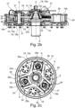
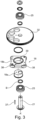
- Each oscillatory driving mechanism comprises at least one eccentric module 18 and a driving device 19 engaged with said module to steer its rotation, said module being connected to the shaft 6 by a mechanical member 20 arranged to transform the eccentric rotation of said module into an oscillation of the shaft 6 of the drum 5.
- the eccentric module(s) 18 is (are) mounted for rotation on the driven body 10, the mechanical member 20 being arranged to transmit the rotation of said driven body to the shaft 6.
- the rotational and oscillatory driving mechanisms are implemented in a particularly simple and compact manner, while presenting an improved resistance to the mechanical constraints transmitted by the shaker rods 9.
- each oscillatory driving mechanism comprises three eccentric modules 18 that are angularly distributed on the driven body 10, which enables a better repartition of the oscillatory efforts around the shaft 6 of the drum 5.
- the oscillatory driving mechanism comprises three planet shafts 21 that are each mounted for rotation on the driven body 10 about respectively a planet vertical axis A', each eccentric module 18 being mounted on respectively one planet shaft 21.
- Each driven body 10 comprises a lower plate 10a on which the toothed crown 16 is associated in rotation, said lower plate comprising a central bore 22 wherein the shaft 6 is mounted for free rotation about the vertical axis A, in particular by means of a ball bearing 23.
- Each driven body 10 also comprises an upper plate 10b that is mounted onto the lower plate 10a, in particular by means of several bolts 24 that also ensures the mounting of the toothed crown 16, each planet shaft 21 comprising upper and lower ends that are mounted for rotation on respectively the upper 10b and lower 10a plates, in particular by means of roller bearings 25.
- Each driven body 10 comprises three reinforcement blocks 26 that are mounted between the upper 10b and lower 10a plates while being angularly distributed around the vertical axis A, so as to ensure an improved distribution of said reinforcement within the driven body 10.
- the driven bodies 10 comprise each three lubrication means 27 that are mounted on the upper plate 10b adjacent respectively one planet shaft 21.
- the harvesting unit comprises a second central horizontal rotating shaft 28 that is connected through transmission means, for example gearing means, a transmission chain and/or a transmission belt, to a second power input 29, so as to be driven in rotation according to the power source provided at said second input.
- transmission means for example gearing means, a transmission chain and/or a transmission belt
- each drum 5 comprise a speed reducer 30 that is connected to the second input 29 through the second horizontal shaft 28, the driving device 19 of said mechanism comprising an upper piece 19a that is mounted for rotation about the vertical axis A at the output of said reducer, so as to be driven in rotation by the power provided by said reducer.
- the driving device 19 comprises a lower piece 19b associated in rotation with the upper piece 19a, said lower piece comprising a toothed sun gear 31 that is geared with planet gears 32 that are each associated in rotation to respectively a planet shaft 21, so as to steer the rotation of each eccentric module 18.
- the upper plate 10b comprises a central bore 33 wherein the lower piece 19b with the sun gear 31 is mounted for rotation, for example by means of a ball bearing 34.
- the sun gear 31 is mounted for rotation around the shaft 6 of the drum 5 by means of a ball bearing 35.
- the mechanical member 20 comprises windows 36 wherein respectively one eccentric module is mounted, said mounting being operable to transform the rotation of said eccentric module into an oscillation of the shaft 6.
- the mechanical member 20 comprises a central bore 20a wherein the shaft 6 is fixedly mounted, and three lobes 20b that are angularly distributed around the shaft 6 and that comprise each such a window 36.
- the oscillatory driving mechanism can comprise two eccentric modules of different eccentricity, but having the same external dimensions which are axially spaced from each other along a planet shaft 21, said planet shaft being mounted in translation along the corresponding planet vertical axis A' for allowing selective mounting of one of said modules inside the window 36.
- the operator of the harvesting machine can selectively shift the corresponding eccentric module into the window 36, for example through command means provided for that purpose into the driver station.
- the two eccentric modules can be mounted at a fixed vertical position on the planet shaft 21 and the mechanical member 20 can be shifted vertically to make the window or windows 36 engage the one or other eccentric module.
- the eccentric modules 18 comprise each a cylindrical base 18a that is mounted on the corresponding planet shaft 21 so that the revolution axis B of said base is offset from the planet vertical axis A', said base being rotatably coupled to an envelope 18b that is arranged inside the window 36.
- cylindrical base 18a is axially stacked under the planet gear 32, so as to improve the compactness of the assembly.
- the cylindrical base 18a is fixed to the planet gear 32, in particular by means of a bolt 37.
- the envelope 18b is mounted for radial translation inside the window 36, while being immobilised in the circumferential direction, so as to exert circumferential pushing forces alternatively against the opposite radial sides 36a of said window upon rotation of the planet shaft 21, and then to generate alternative oscillations of the mechanical member 20 about the vertical axis A.
- the envelope 18b is provided with at least two rollers 38 that are mounted for rotation on respectively one lateral side of said envelope, said rollers being arranged to roll along respectively one radial side 36a of the window 36 upon radial translation of the envelope 18b inside said window, so as to facilitate said radial translation.
- the envelope 18b has a substantially square shape with rounded corners and comprises four rollers 38 that are each mounted for rotation on one of said corners. Moreover, the envelope 18b comprises a central bore 39 wherein the cylindrical base is fitted.
- the eccentric module may comprise a crank connected to the planet gear 6 and having an eccentric shaft portion provided with a roller that is guided in a radially extending slot in the mechanical member, the slot taking the function of the window in the above embodiment.
- Such mounting would not require an envelope.
- the driving mechanisms may also be provided at the lower end of the drum shaft 6, for easier access during repair and servicing operations.
Landscapes
- Engineering & Computer Science (AREA)
- General Engineering & Computer Science (AREA)
- Life Sciences & Earth Sciences (AREA)
- Environmental Sciences (AREA)
- Mechanical Engineering (AREA)
- Harvesting Machines For Specific Crops (AREA)
- Sink And Installation For Waste Water (AREA)
Claims (15)
- Unité de récolte comprenant un châssis (1) destiné à être déplacé le long des rangs de plantation à récolter, et un système de secouage comprenant au moins un dispositif de secouage (3), ledit dispositif de secouage comprenant :- un tambour (5) utilisable pour détacher une récolte desdits plants, ledit tambour comprenant un arbre de tambour (6) monté sur ledit châssis pour effectuer des rotations autour d'un axe vertical (A) et des organes de secouage (7) montés sur ledit arbre de tambour ;- un mécanisme d'entraînement rotatif dudit tambour (5), ledit mécanisme comprenant un corps entraîné (10) et un premier dispositif d'entraînement (11) en prise avec ledit corps entraîné pour diriger sa rotation autour dudit axe vertical (A) ;- un mécanisme d'entraînement oscillatoire dudit tambour (5) autour dudit axe vertical (A), ledit mécanisme comprenant au moins un module excentrique (18) et un second dispositif d'entraînement (19) en prise avec ledit module pour diriger sa rotation, ledit module étant relié par entraînement à l'arbre de tambour (6) par un élément mécanique (20) pouvant fonctionner pour transformer la rotation excentrique dudit module en une oscillation dudit arbre de tambour (6), le module excentrique (18) est monté pour effectuer des rotations sur le corps entraîné (10) du mécanisme d'entraînement rotatif, l'élément mécanique (20) étant agencé pour transmettre la rotation dudit corps entraîné à l'arbre du tambour (6) ;ladite unité de récolte étant caractérisée en ce que l'élément mécanique (20) comprend une fenêtre (36) dans laquelle le module excentrique (18) est monté, le montage dudit module excentrique dans ladite fenêtre pouvant être actionné pour transformer la rotation dudit module excentrique (18) en une oscillation de l'élément mécanique (20).
- Unité de récolte selon la Revendication 1, caractérisée en ce que le mécanisme d'entraînement oscillatoire comprend un arbre planétaire (21) monté pour effectuer des rotations sur le corps entraîné (10) autour d'un axe vertical planétaire (A'), le module excentrique (18) étant monté sur ledit arbre planétaire.
- Unité de récolte selon la Revendication 1 ou la Revendication 2, caractérisée en ce que le module excentrique (18) est monté pour un déplacement radial par rapport à l'organe mécanique (20) à l'intérieur de la fenêtre (36).
- Unité de récolte selon l'une quelconque des revendications 1 à 3, caractérisée en ce que le module excentrique (18) est immobilisé en direction circonférentielle par rapport à l'organe mécanique (20) à l'intérieur de la fenêtre (36).
- Unité de récolte selon l'une quelconque des revendications 2 à 4, caractérisée en ce que le module excentrique (18) comprend une base cylindrique (18a) qui est solidaire de l'arbre planétaire (21) de manière à ce que l'axe (B) de ladite base cylindrique soit décalé par rapport à l'axe vertical planétaire (A'), ladite base cylindrique étant couplée de manière rotative à une protection (18b) qui est disposée à l'intérieur de la fenêtre (36).
- Unité de récolte selon la Revendication 5, caractérisée en ce que la protection (18b) comprend au moins deux rouleaux (38) montés pour effectuer des rotations sur les côtés opposés de ladite protection, lesdits rouleaux étant agencés pour rouler sur les côtés opposés respectifs (36a) de la fenêtre (36) lors du déplacement radial de la protection (18b) à l'intérieur de ladite fenêtre.
- Unité de récolte selon l'une quelconque des revendications 2 à 6, caractérisée en ce que le mécanisme d'entraînement oscillatoire comprend deux modules excentriques (18) d'excentricité différente qui sont espacés l'un de l'autre de manière axiale le long de l'arbre planétaire (21), ledit arbre planétaire étant monté pour se déplacer le long de l'axe vertical planétaire (A') pour permettre le montage sélectif de l'un desdits modules à l'intérieur de la fenêtre (36).
- Unité de récolte selon l'une quelconque des revendications 2 à 7, caractérisée en ce que le second dispositif d'entraînement (19) du mécanisme d'entraînement oscillatoire comprend un planétaire (31) monté pour effectuer des rotations autour de l'axe vertical (A), ledit planétaire en prise avec un satellite (32) associé en rotation autour de l'arbre planétaire (21) pour diriger la rotation du module excentrique (18).
- Unité de récolte selon la Revendication 8 lorsqu'elle dépend de la Revendication 5, caractérisée en ce que la base cylindrique (18a) est axialement empilée et fixée sous le satellite (32).
- Unité de récolte selon l'une quelconque des revendications 2 à 9, caractérisée en ce que le corps entraîné (10) comprend une plaque supérieure (10b) sur laquelle l'arbre planétaire (21) est monté pour effectuer des rotations.
- Unité de récolte selon l'une quelconque des revendications 1 à 10, caractérisée en ce que le mécanisme d'entraînement oscillatoire comprend trois modules excentriques (18) répartis de manière angulaire sur le corps entraîné (10).
- Unité de récolte selon la Revendication 11, caractérisée en ce que l'élément mécanique (20) comprend trois lobes (20b) répartis de manière angulaire autour de l'arbre de tambour (6), chaque lobe (20b) comprenant une fenêtre (36) dans laquelle respectivement un module excentrique (18) est monté.
- Unité de récolte selon l'une quelconque des revendications 1 à 12, caractérisée en ce que le châssis (1) délimite un tunnel (4) pour l'introduction successive des plants à récolter, le système de secouage comprenant deux dispositifs de secouage (3) disposés respectivement sur un côté dudit tunnel.
- Engin de récolte comprenant une structure de support motorisée mobile le long des rangs de plantation, une unité de récolte selon l'une quelconque des revendications 1 à 13 étant montée sur ladite structure de support motorisée pour détacher la récolte desdits plants.
- Engin de récolte selon la Revendication 14, caractérisée en ce qu'elle comprend des moyens de commande du dispositif d'entraînement (11) de telle sorte que la vitesse d'entraînement en rotation du tambour (5) minimum requis soit réglée en fonction de la vitesse de déplacement de la structure de support.
Applications Claiming Priority (2)
| Application Number | Priority Date | Filing Date | Title |
|---|---|---|---|
| FR1857780 | 2018-08-29 | ||
| PCT/EP2019/072695 WO2020043656A1 (fr) | 2018-08-29 | 2019-08-26 | Unité de récolte |
Publications (2)
| Publication Number | Publication Date |
|---|---|
| EP3843527A1 EP3843527A1 (fr) | 2021-07-07 |
| EP3843527B1 true EP3843527B1 (fr) | 2024-02-28 |
Family
ID=63963220
Family Applications (1)
| Application Number | Title | Priority Date | Filing Date |
|---|---|---|---|
| EP19759351.0A Active EP3843527B1 (fr) | 2018-08-29 | 2019-08-26 | Unité de récolte |
Country Status (6)
| Country | Link |
|---|---|
| US (1) | US12279559B2 (fr) |
| EP (1) | EP3843527B1 (fr) |
| CN (1) | CN112839506B (fr) |
| AU (1) | AU2019328256B2 (fr) |
| ES (1) | ES2988925T3 (fr) |
| WO (1) | WO2020043656A1 (fr) |
Families Citing this family (5)
| Publication number | Priority date | Publication date | Assignee | Title |
|---|---|---|---|---|
| CN114271106A (zh) * | 2021-11-10 | 2022-04-05 | 铁建重工新疆有限公司 | 一种惯性振动果秧分离装置 |
| CN114271105A (zh) * | 2021-11-10 | 2022-04-05 | 铁建重工新疆有限公司 | 一种惯性振动果秧分离装置 |
| EP4527184A1 (fr) * | 2023-09-21 | 2025-03-26 | CNH Industrial France | Unité de récolte comprenant des tapis collecteurs de récolte |
| US20250268141A1 (en) * | 2024-02-26 | 2025-08-28 | Cnh Industrial France S.A.S | Wobble box for a shaker of an agricultural harvester |
| EP4620289A1 (fr) * | 2024-03-22 | 2025-09-24 | CNH Industrial France S.A.S. | Unité de récolte avec système agitateur |
Family Cites Families (31)
| Publication number | Priority date | Publication date | Assignee | Title |
|---|---|---|---|---|
| US3344591A (en) | 1964-04-27 | 1967-10-03 | Oeco Corp | Moving carriage mechanical berry harvester with rotationally oscillative shakers |
| US3507162A (en) | 1967-12-28 | 1970-04-21 | Nissei Kk | Cycloplanetary gearing having a varying output speed ratio |
| GB1435013A (en) * | 1973-05-24 | 1976-05-12 | Lincoln College | Harvesting apparatus |
| US4114463A (en) * | 1975-07-09 | 1978-09-19 | New Zealand Inventions Development Authority | Drive means and harvesting apparatus incorporating same |
| NZ179552A (en) | 1975-12-15 | 1979-11-01 | Peco Ltd | Drive arrangement for vibrating shaker head assemblies of a straddle type berry fruit haryester |
| US4265080A (en) * | 1978-03-10 | 1981-05-05 | Goldsmith Sydney A | Harvesting apparatus |
| GB2033197B (en) * | 1978-11-08 | 1982-12-08 | Pattenden Engineering Ltd | Harvesting machine |
| MX150351A (es) | 1979-03-08 | 1984-04-23 | Fmc Corp | Mejoras en unidad sacudidora para segadora para recoger siembras utiles de plantas/semejantes a arbustos |
| FR2558556B1 (fr) | 1984-01-23 | 1989-04-07 | Manutention Stockage Cie | Dispositif mecanique de transformation d'un mouvement circulaire a vitesse constante en mouvement circulaire a vitesse variable periodiquement |
| SU1371598A2 (ru) * | 1985-05-23 | 1988-02-07 | Горский Сельскохозяйственный Институт | Встр хиватель годоуборочной машины |
| GB8619504D0 (en) | 1986-08-11 | 1986-09-24 | Rockwell Graphic Systems Ltd | Accelerating drive member |
| US5170614A (en) | 1988-01-29 | 1992-12-15 | Clemson University | Harvesting machinery |
| US4974405A (en) | 1989-10-06 | 1990-12-04 | Littau Eugene G | Harvester with rotationally oscillatable cylindrical shakers |
| US5316519A (en) * | 1992-05-07 | 1994-05-31 | Johnson Farm Machinery Company, Inc. | Multiple weight drum shaker |
| US5908352A (en) | 1995-10-06 | 1999-06-01 | Fmc Corporation | Adjustable four-weight shaker head |
| US5685773A (en) | 1995-10-06 | 1997-11-11 | Fmc Corporation | Adjustable four-weight shaker head |
| AU780423B2 (en) | 1999-10-07 | 2005-03-17 | Ag-Right Enterprises, Inc. | Direct drive vibratory shaker |
| US20050034441A1 (en) | 2003-08-15 | 2005-02-17 | Los Olivares De Venado Tuerto S.A. | Olive harvesting machine |
| DE102004006139A1 (de) | 2004-02-07 | 2005-08-25 | Zf Friedrichshafen Ag | Stellantrieb, insbesondere zur Betätigung einer Reibungskupplung oder eines Getriebes bei einem Kraftfahrzeug |
| US20080060336A1 (en) * | 2006-09-11 | 2008-03-13 | Los Olivares De Venado Tuerto S.A. | Rotovibrating device applicable to knocking down rod headers of harvesting machines |
| CN101482163B (zh) | 2008-12-30 | 2013-05-15 | 石河子大学 | 农作物藤果分离装置的摆转机构 |
| CN201351725Y (zh) | 2008-12-30 | 2009-11-25 | 石河子大学 | 行星齿轮摆转机构 |
| US8887831B2 (en) | 2011-11-17 | 2014-11-18 | Black & Decker Inc. | Transmission for power tool with variable speed ratio |
| AT512571B1 (de) | 2012-01-25 | 2013-12-15 | Fronius Int Gmbh | Drahtfördervorrichtung für ein schweissgerät beziehungsweise für einen schweissbrenner |
| DE202012012604U1 (de) | 2012-02-24 | 2013-09-10 | Carl Hoffmann Landmaschinenfachbetrieb Gmbh | Erntevorrichtung sowie Fahrzeug mit einer solchen Erntevorrichtung |
| DE202014001781U1 (de) | 2014-03-01 | 2014-04-02 | Carl Hoffmann Landmaschinenfachbetrieb Gmbh | Ausdünnvorrichtung sowie Fahrzeug mit einer solchen Ausdünnvorrichtung |
| FR3045272B1 (fr) | 2015-12-22 | 2018-08-10 | Cnh Industrial France | Machine recolteuse de fruits |
| CN105850374A (zh) * | 2016-04-15 | 2016-08-17 | 浙江大学 | 一种用于枸杞采摘的偏心滚振机构 |
| CN106233924B (zh) | 2016-07-26 | 2019-05-24 | 石河子大学 | 一种番茄果秧分离振动发生器 |
| CN107228164B (zh) | 2017-07-13 | 2023-04-14 | 中冶赛迪技术研究中心有限公司 | 传动比周期性变化的少齿差行星齿轮传动装置 |
| CN207099723U (zh) * | 2017-07-13 | 2018-03-16 | 浙江理工大学 | 一种用于林果的新型夹持振动采收装置 |
-
2019
- 2019-08-26 EP EP19759351.0A patent/EP3843527B1/fr active Active
- 2019-08-26 ES ES19759351T patent/ES2988925T3/es active Active
- 2019-08-26 AU AU2019328256A patent/AU2019328256B2/en active Active
- 2019-08-26 WO PCT/EP2019/072695 patent/WO2020043656A1/fr not_active Ceased
- 2019-08-26 US US17/272,647 patent/US12279559B2/en active Active
- 2019-08-26 CN CN201980064633.XA patent/CN112839506B/zh active Active
Also Published As
| Publication number | Publication date |
|---|---|
| CN112839506A (zh) | 2021-05-25 |
| BR112020005916A2 (pt) | 2021-03-09 |
| EP3843527A1 (fr) | 2021-07-07 |
| ES2988925T3 (es) | 2024-11-22 |
| US20210337732A1 (en) | 2021-11-04 |
| AU2019328256B2 (en) | 2022-10-13 |
| AU2019328256A1 (en) | 2021-03-25 |
| WO2020043656A1 (fr) | 2020-03-05 |
| CN112839506B (zh) | 2023-04-28 |
| US12279559B2 (en) | 2025-04-22 |
Similar Documents
| Publication | Publication Date | Title |
|---|---|---|
| EP3843527B1 (fr) | Unité de récolte | |
| US3344591A (en) | Moving carriage mechanical berry harvester with rotationally oscillative shakers | |
| US4173859A (en) | Harvesting apparatus | |
| FR3045272A1 (fr) | Machine recolteuse de fruits | |
| GB2033197A (en) | Harvesting machine | |
| EP0857015B1 (fr) | Tete secoueuse reglable a quatre poids | |
| US3203159A (en) | Method of harvesting berries and similar produce from their plants | |
| EP2677853B1 (fr) | Unité de récolte de fruits et machine à récolter comprenant une telle unité | |
| EP4620289A1 (fr) | Unité de récolte avec système agitateur | |
| AU2006228421A1 (en) | Shaking machine for harvesting fruit from rows | |
| CN117158191A (zh) | 一种油茶果自动收集机 | |
| BR112020005916B1 (pt) | Unidade de colheita e máquina colhedora | |
| US20080060336A1 (en) | Rotovibrating device applicable to knocking down rod headers of harvesting machines | |
| EP1955583A1 (fr) | Remorque de distribution | |
| US20250268141A1 (en) | Wobble box for a shaker of an agricultural harvester | |
| EP4527184A1 (fr) | Unité de récolte comprenant des tapis collecteurs de récolte | |
| RU2160985C1 (ru) | Стряхиватель плодоуборочного комбайна | |
| CN2405415Y (zh) | 双驱动自动割麦机 | |
| CN201248260Y (zh) | 花生收获机 | |
| CN1520705A (zh) | 自走式花生联合收获机 | |
| CN208338305U (zh) | 收割机 | |
| CN2676599Y (zh) | 拖拉机用玉米、葵花秸秆收割机 | |
| RU2021661C1 (ru) | Роторная корнеклубнеплодоуборочная машина | |
| JPS63129912A (ja) | 歩行形田植機 | |
| BE500050A (fr) |
Legal Events
| Date | Code | Title | Description |
|---|---|---|---|
| STAA | Information on the status of an ep patent application or granted ep patent |
Free format text: STATUS: UNKNOWN |
|
| STAA | Information on the status of an ep patent application or granted ep patent |
Free format text: STATUS: THE INTERNATIONAL PUBLICATION HAS BEEN MADE |
|
| STAA | Information on the status of an ep patent application or granted ep patent |
Free format text: STATUS: REQUEST FOR EXAMINATION WAS MADE |
|
| PUAI | Public reference made under article 153(3) epc to a published international application that has entered the european phase |
Free format text: ORIGINAL CODE: 0009012 |
|
| 17P | Request for examination filed |
Effective date: 20210329 |
|
| AK | Designated contracting states |
Kind code of ref document: A1 Designated state(s): AL AT BE BG CH CY CZ DE DK EE ES FI FR GB GR HR HU IE IS IT LI LT LU LV MC MK MT NL NO PL PT RO RS SE SI SK SM TR |
|
| DAV | Request for validation of the european patent (deleted) | ||
| DAX | Request for extension of the european patent (deleted) | ||
| GRAP | Despatch of communication of intention to grant a patent |
Free format text: ORIGINAL CODE: EPIDOSNIGR1 |
|
| STAA | Information on the status of an ep patent application or granted ep patent |
Free format text: STATUS: GRANT OF PATENT IS INTENDED |
|
| INTG | Intention to grant announced |
Effective date: 20230928 |
|
| GRAS | Grant fee paid |
Free format text: ORIGINAL CODE: EPIDOSNIGR3 |
|
| GRAA | (expected) grant |
Free format text: ORIGINAL CODE: 0009210 |
|
| STAA | Information on the status of an ep patent application or granted ep patent |
Free format text: STATUS: THE PATENT HAS BEEN GRANTED |
|
| AK | Designated contracting states |
Kind code of ref document: B1 Designated state(s): AL AT BE BG CH CY CZ DE DK EE ES FI FR GB GR HR HU IE IS IT LI LT LU LV MC MK MT NL NO PL PT RO RS SE SI SK SM TR |
|
| REG | Reference to a national code |
Ref country code: GB Ref legal event code: FG4D |
|
| REG | Reference to a national code |
Ref country code: CH Ref legal event code: EP |
|
| REG | Reference to a national code |
Ref country code: DE Ref legal event code: R096 Ref document number: 602019047354 Country of ref document: DE |
|
| REG | Reference to a national code |
Ref country code: IE Ref legal event code: FG4D |
|
| REG | Reference to a national code |
Ref country code: LT Ref legal event code: MG9D |
|
| PG25 | Lapsed in a contracting state [announced via postgrant information from national office to epo] |
Ref country code: IS Free format text: LAPSE BECAUSE OF FAILURE TO SUBMIT A TRANSLATION OF THE DESCRIPTION OR TO PAY THE FEE WITHIN THE PRESCRIBED TIME-LIMIT Effective date: 20240628 |
|
| REG | Reference to a national code |
Ref country code: NL Ref legal event code: MP Effective date: 20240228 |
|
| PG25 | Lapsed in a contracting state [announced via postgrant information from national office to epo] |
Ref country code: LT Free format text: LAPSE BECAUSE OF FAILURE TO SUBMIT A TRANSLATION OF THE DESCRIPTION OR TO PAY THE FEE WITHIN THE PRESCRIBED TIME-LIMIT Effective date: 20240228 |
|
| PG25 | Lapsed in a contracting state [announced via postgrant information from national office to epo] |
Ref country code: GR Free format text: LAPSE BECAUSE OF FAILURE TO SUBMIT A TRANSLATION OF THE DESCRIPTION OR TO PAY THE FEE WITHIN THE PRESCRIBED TIME-LIMIT Effective date: 20240529 |
|
| PG25 | Lapsed in a contracting state [announced via postgrant information from national office to epo] |
Ref country code: RS Free format text: LAPSE BECAUSE OF FAILURE TO SUBMIT A TRANSLATION OF THE DESCRIPTION OR TO PAY THE FEE WITHIN THE PRESCRIBED TIME-LIMIT Effective date: 20240528 Ref country code: HR Free format text: LAPSE BECAUSE OF FAILURE TO SUBMIT A TRANSLATION OF THE DESCRIPTION OR TO PAY THE FEE WITHIN THE PRESCRIBED TIME-LIMIT Effective date: 20240228 Ref country code: NL Free format text: LAPSE BECAUSE OF FAILURE TO SUBMIT A TRANSLATION OF THE DESCRIPTION OR TO PAY THE FEE WITHIN THE PRESCRIBED TIME-LIMIT Effective date: 20240228 |
|
| PG25 | Lapsed in a contracting state [announced via postgrant information from national office to epo] |
Ref country code: RS Free format text: LAPSE BECAUSE OF FAILURE TO SUBMIT A TRANSLATION OF THE DESCRIPTION OR TO PAY THE FEE WITHIN THE PRESCRIBED TIME-LIMIT Effective date: 20240528 Ref country code: NO Free format text: LAPSE BECAUSE OF FAILURE TO SUBMIT A TRANSLATION OF THE DESCRIPTION OR TO PAY THE FEE WITHIN THE PRESCRIBED TIME-LIMIT Effective date: 20240528 Ref country code: NL Free format text: LAPSE BECAUSE OF FAILURE TO SUBMIT A TRANSLATION OF THE DESCRIPTION OR TO PAY THE FEE WITHIN THE PRESCRIBED TIME-LIMIT Effective date: 20240228 Ref country code: LT Free format text: LAPSE BECAUSE OF FAILURE TO SUBMIT A TRANSLATION OF THE DESCRIPTION OR TO PAY THE FEE WITHIN THE PRESCRIBED TIME-LIMIT Effective date: 20240228 Ref country code: IS Free format text: LAPSE BECAUSE OF FAILURE TO SUBMIT A TRANSLATION OF THE DESCRIPTION OR TO PAY THE FEE WITHIN THE PRESCRIBED TIME-LIMIT Effective date: 20240628 Ref country code: HR Free format text: LAPSE BECAUSE OF FAILURE TO SUBMIT A TRANSLATION OF THE DESCRIPTION OR TO PAY THE FEE WITHIN THE PRESCRIBED TIME-LIMIT Effective date: 20240228 Ref country code: GR Free format text: LAPSE BECAUSE OF FAILURE TO SUBMIT A TRANSLATION OF THE DESCRIPTION OR TO PAY THE FEE WITHIN THE PRESCRIBED TIME-LIMIT Effective date: 20240529 Ref country code: FI Free format text: LAPSE BECAUSE OF FAILURE TO SUBMIT A TRANSLATION OF THE DESCRIPTION OR TO PAY THE FEE WITHIN THE PRESCRIBED TIME-LIMIT Effective date: 20240228 Ref country code: BG Free format text: LAPSE BECAUSE OF FAILURE TO SUBMIT A TRANSLATION OF THE DESCRIPTION OR TO PAY THE FEE WITHIN THE PRESCRIBED TIME-LIMIT Effective date: 20240228 |
|
| PG25 | Lapsed in a contracting state [announced via postgrant information from national office to epo] |
Ref country code: PT Free format text: LAPSE BECAUSE OF FAILURE TO SUBMIT A TRANSLATION OF THE DESCRIPTION OR TO PAY THE FEE WITHIN THE PRESCRIBED TIME-LIMIT Effective date: 20240628 Ref country code: PL Free format text: LAPSE BECAUSE OF FAILURE TO SUBMIT A TRANSLATION OF THE DESCRIPTION OR TO PAY THE FEE WITHIN THE PRESCRIBED TIME-LIMIT Effective date: 20240228 |
|
| REG | Reference to a national code |
Ref country code: AT Ref legal event code: MK05 Ref document number: 1660280 Country of ref document: AT Kind code of ref document: T Effective date: 20240228 |
|
| PG25 | Lapsed in a contracting state [announced via postgrant information from national office to epo] |
Ref country code: SE Free format text: LAPSE BECAUSE OF FAILURE TO SUBMIT A TRANSLATION OF THE DESCRIPTION OR TO PAY THE FEE WITHIN THE PRESCRIBED TIME-LIMIT Effective date: 20240228 Ref country code: PT Free format text: LAPSE BECAUSE OF FAILURE TO SUBMIT A TRANSLATION OF THE DESCRIPTION OR TO PAY THE FEE WITHIN THE PRESCRIBED TIME-LIMIT Effective date: 20240628 Ref country code: PL Free format text: LAPSE BECAUSE OF FAILURE TO SUBMIT A TRANSLATION OF THE DESCRIPTION OR TO PAY THE FEE WITHIN THE PRESCRIBED TIME-LIMIT Effective date: 20240228 Ref country code: LV Free format text: LAPSE BECAUSE OF FAILURE TO SUBMIT A TRANSLATION OF THE DESCRIPTION OR TO PAY THE FEE WITHIN THE PRESCRIBED TIME-LIMIT Effective date: 20240228 |
|
| PG25 | Lapsed in a contracting state [announced via postgrant information from national office to epo] |
Ref country code: DK Free format text: LAPSE BECAUSE OF FAILURE TO SUBMIT A TRANSLATION OF THE DESCRIPTION OR TO PAY THE FEE WITHIN THE PRESCRIBED TIME-LIMIT Effective date: 20240228 |
|
| PG25 | Lapsed in a contracting state [announced via postgrant information from national office to epo] |
Ref country code: SM Free format text: LAPSE BECAUSE OF FAILURE TO SUBMIT A TRANSLATION OF THE DESCRIPTION OR TO PAY THE FEE WITHIN THE PRESCRIBED TIME-LIMIT Effective date: 20240228 |
|
| PG25 | Lapsed in a contracting state [announced via postgrant information from national office to epo] |
Ref country code: EE Free format text: LAPSE BECAUSE OF FAILURE TO SUBMIT A TRANSLATION OF THE DESCRIPTION OR TO PAY THE FEE WITHIN THE PRESCRIBED TIME-LIMIT Effective date: 20240228 Ref country code: CZ Free format text: LAPSE BECAUSE OF FAILURE TO SUBMIT A TRANSLATION OF THE DESCRIPTION OR TO PAY THE FEE WITHIN THE PRESCRIBED TIME-LIMIT Effective date: 20240228 |
|
| PG25 | Lapsed in a contracting state [announced via postgrant information from national office to epo] |
Ref country code: AT Free format text: LAPSE BECAUSE OF FAILURE TO SUBMIT A TRANSLATION OF THE DESCRIPTION OR TO PAY THE FEE WITHIN THE PRESCRIBED TIME-LIMIT Effective date: 20240228 |
|
| PG25 | Lapsed in a contracting state [announced via postgrant information from national office to epo] |
Ref country code: SK Free format text: LAPSE BECAUSE OF FAILURE TO SUBMIT A TRANSLATION OF THE DESCRIPTION OR TO PAY THE FEE WITHIN THE PRESCRIBED TIME-LIMIT Effective date: 20240228 |
|
| PG25 | Lapsed in a contracting state [announced via postgrant information from national office to epo] |
Ref country code: SM Free format text: LAPSE BECAUSE OF FAILURE TO SUBMIT A TRANSLATION OF THE DESCRIPTION OR TO PAY THE FEE WITHIN THE PRESCRIBED TIME-LIMIT Effective date: 20240228 Ref country code: SK Free format text: LAPSE BECAUSE OF FAILURE TO SUBMIT A TRANSLATION OF THE DESCRIPTION OR TO PAY THE FEE WITHIN THE PRESCRIBED TIME-LIMIT Effective date: 20240228 Ref country code: RO Free format text: LAPSE BECAUSE OF FAILURE TO SUBMIT A TRANSLATION OF THE DESCRIPTION OR TO PAY THE FEE WITHIN THE PRESCRIBED TIME-LIMIT Effective date: 20240228 Ref country code: EE Free format text: LAPSE BECAUSE OF FAILURE TO SUBMIT A TRANSLATION OF THE DESCRIPTION OR TO PAY THE FEE WITHIN THE PRESCRIBED TIME-LIMIT Effective date: 20240228 Ref country code: DK Free format text: LAPSE BECAUSE OF FAILURE TO SUBMIT A TRANSLATION OF THE DESCRIPTION OR TO PAY THE FEE WITHIN THE PRESCRIBED TIME-LIMIT Effective date: 20240228 Ref country code: CZ Free format text: LAPSE BECAUSE OF FAILURE TO SUBMIT A TRANSLATION OF THE DESCRIPTION OR TO PAY THE FEE WITHIN THE PRESCRIBED TIME-LIMIT Effective date: 20240228 Ref country code: AT Free format text: LAPSE BECAUSE OF FAILURE TO SUBMIT A TRANSLATION OF THE DESCRIPTION OR TO PAY THE FEE WITHIN THE PRESCRIBED TIME-LIMIT Effective date: 20240228 |
|
| REG | Reference to a national code |
Ref country code: ES Ref legal event code: FG2A Ref document number: 2988925 Country of ref document: ES Kind code of ref document: T3 Effective date: 20241122 |
|
| REG | Reference to a national code |
Ref country code: DE Ref legal event code: R097 Ref document number: 602019047354 Country of ref document: DE |
|
| PLBE | No opposition filed within time limit |
Free format text: ORIGINAL CODE: 0009261 |
|
| STAA | Information on the status of an ep patent application or granted ep patent |
Free format text: STATUS: NO OPPOSITION FILED WITHIN TIME LIMIT |
|
| 26N | No opposition filed |
Effective date: 20241129 |
|
| REG | Reference to a national code |
Ref country code: CH Ref legal event code: PL |
|
| PG25 | Lapsed in a contracting state [announced via postgrant information from national office to epo] |
Ref country code: LU Free format text: LAPSE BECAUSE OF NON-PAYMENT OF DUE FEES Effective date: 20240826 |
|
| GBPC | Gb: european patent ceased through non-payment of renewal fee |
Effective date: 20240826 |
|
| PG25 | Lapsed in a contracting state [announced via postgrant information from national office to epo] |
Ref country code: MC Free format text: LAPSE BECAUSE OF FAILURE TO SUBMIT A TRANSLATION OF THE DESCRIPTION OR TO PAY THE FEE WITHIN THE PRESCRIBED TIME-LIMIT Effective date: 20240228 Ref country code: CH Free format text: LAPSE BECAUSE OF NON-PAYMENT OF DUE FEES Effective date: 20240831 Ref country code: SI Free format text: LAPSE BECAUSE OF FAILURE TO SUBMIT A TRANSLATION OF THE DESCRIPTION OR TO PAY THE FEE WITHIN THE PRESCRIBED TIME-LIMIT Effective date: 20240228 |
|
| REG | Reference to a national code |
Ref country code: BE Ref legal event code: MM Effective date: 20240831 |
|
| PG25 | Lapsed in a contracting state [announced via postgrant information from national office to epo] |
Ref country code: GB Free format text: LAPSE BECAUSE OF NON-PAYMENT OF DUE FEES Effective date: 20240826 |
|
| PG25 | Lapsed in a contracting state [announced via postgrant information from national office to epo] |
Ref country code: BE Free format text: LAPSE BECAUSE OF NON-PAYMENT OF DUE FEES Effective date: 20240831 |
|
| PG25 | Lapsed in a contracting state [announced via postgrant information from national office to epo] |
Ref country code: IE Free format text: LAPSE BECAUSE OF NON-PAYMENT OF DUE FEES Effective date: 20240826 |
|
| PGFP | Annual fee paid to national office [announced via postgrant information from national office to epo] |
Ref country code: ES Payment date: 20250916 Year of fee payment: 7 |
|
| PGFP | Annual fee paid to national office [announced via postgrant information from national office to epo] |
Ref country code: DE Payment date: 20250827 Year of fee payment: 7 |
|
| PGFP | Annual fee paid to national office [announced via postgrant information from national office to epo] |
Ref country code: IT Payment date: 20250825 Year of fee payment: 7 |
|
| PGFP | Annual fee paid to national office [announced via postgrant information from national office to epo] |
Ref country code: FR Payment date: 20250825 Year of fee payment: 7 |
|
| PG25 | Lapsed in a contracting state [announced via postgrant information from national office to epo] |
Ref country code: CY Free format text: LAPSE BECAUSE OF FAILURE TO SUBMIT A TRANSLATION OF THE DESCRIPTION OR TO PAY THE FEE WITHIN THE PRESCRIBED TIME-LIMIT; INVALID AB INITIO Effective date: 20190826 |
|
| PG25 | Lapsed in a contracting state [announced via postgrant information from national office to epo] |
Ref country code: HU Free format text: LAPSE BECAUSE OF FAILURE TO SUBMIT A TRANSLATION OF THE DESCRIPTION OR TO PAY THE FEE WITHIN THE PRESCRIBED TIME-LIMIT; INVALID AB INITIO Effective date: 20190826 |