EP3843678B1 - Pansements destinés à une interpénétration tissulaire réduite - Google Patents
Pansements destinés à une interpénétration tissulaire réduite Download PDFInfo
- Publication number
- EP3843678B1 EP3843678B1 EP19736897.0A EP19736897A EP3843678B1 EP 3843678 B1 EP3843678 B1 EP 3843678B1 EP 19736897 A EP19736897 A EP 19736897A EP 3843678 B1 EP3843678 B1 EP 3843678B1
- Authority
- EP
- European Patent Office
- Prior art keywords
- manifold
- dressing
- biopolymer layer
- pressure
- previous
- Prior art date
- Legal status (The legal status is an assumption and is not a legal conclusion. Google has not performed a legal analysis and makes no representation as to the accuracy of the status listed.)
- Active
Links
Images




Classifications
-
- A—HUMAN NECESSITIES
- A61—MEDICAL OR VETERINARY SCIENCE; HYGIENE
- A61F—FILTERS IMPLANTABLE INTO BLOOD VESSELS; PROSTHESES; DEVICES PROVIDING PATENCY TO, OR PREVENTING COLLAPSING OF, TUBULAR STRUCTURES OF THE BODY, e.g. STENTS; ORTHOPAEDIC, NURSING OR CONTRACEPTIVE DEVICES; FOMENTATION; TREATMENT OR PROTECTION OF EYES OR EARS; BANDAGES, DRESSINGS OR ABSORBENT PADS; FIRST-AID KITS
- A61F13/00—Bandages or dressings; Absorbent pads
- A61F13/05—Bandages or dressings; Absorbent pads specially adapted for use with sub-pressure or over-pressure therapy, wound drainage or wound irrigation, e.g. for use with negative-pressure wound therapy [NPWT]
-
- A—HUMAN NECESSITIES
- A61—MEDICAL OR VETERINARY SCIENCE; HYGIENE
- A61F—FILTERS IMPLANTABLE INTO BLOOD VESSELS; PROSTHESES; DEVICES PROVIDING PATENCY TO, OR PREVENTING COLLAPSING OF, TUBULAR STRUCTURES OF THE BODY, e.g. STENTS; ORTHOPAEDIC, NURSING OR CONTRACEPTIVE DEVICES; FOMENTATION; TREATMENT OR PROTECTION OF EYES OR EARS; BANDAGES, DRESSINGS OR ABSORBENT PADS; FIRST-AID KITS
- A61F13/00—Bandages or dressings; Absorbent pads
- A61F13/01—Non-adhesive bandages or dressings
- A61F13/01021—Non-adhesive bandages or dressings characterised by the structure of the dressing
- A61F13/01029—Non-adhesive bandages or dressings characterised by the structure of the dressing made of multiple layers
-
- A—HUMAN NECESSITIES
- A61—MEDICAL OR VETERINARY SCIENCE; HYGIENE
- A61L—METHODS OR APPARATUS FOR STERILISING MATERIALS OR OBJECTS IN GENERAL; DISINFECTION, STERILISATION OR DEODORISATION OF AIR; CHEMICAL ASPECTS OF BANDAGES, DRESSINGS, ABSORBENT PADS OR SURGICAL ARTICLES; MATERIALS FOR BANDAGES, DRESSINGS, ABSORBENT PADS OR SURGICAL ARTICLES
- A61L15/00—Chemical aspects of, or use of materials for, bandages, dressings or absorbent pads
- A61L15/16—Bandages, dressings or absorbent pads for physiological fluids such as urine or blood, e.g. sanitary towels, tampons
- A61L15/22—Bandages, dressings or absorbent pads for physiological fluids such as urine or blood, e.g. sanitary towels, tampons containing macromolecular materials
- A61L15/28—Polysaccharides or their derivatives
-
- A—HUMAN NECESSITIES
- A61—MEDICAL OR VETERINARY SCIENCE; HYGIENE
- A61L—METHODS OR APPARATUS FOR STERILISING MATERIALS OR OBJECTS IN GENERAL; DISINFECTION, STERILISATION OR DEODORISATION OF AIR; CHEMICAL ASPECTS OF BANDAGES, DRESSINGS, ABSORBENT PADS OR SURGICAL ARTICLES; MATERIALS FOR BANDAGES, DRESSINGS, ABSORBENT PADS OR SURGICAL ARTICLES
- A61L15/00—Chemical aspects of, or use of materials for, bandages, dressings or absorbent pads
- A61L15/16—Bandages, dressings or absorbent pads for physiological fluids such as urine or blood, e.g. sanitary towels, tampons
- A61L15/22—Bandages, dressings or absorbent pads for physiological fluids such as urine or blood, e.g. sanitary towels, tampons containing macromolecular materials
- A61L15/32—Proteins, polypeptides; Degradation products or derivatives thereof, e.g. albumin, collagen, fibrin, gelatin
- A61L15/325—Collagen
-
- A—HUMAN NECESSITIES
- A61—MEDICAL OR VETERINARY SCIENCE; HYGIENE
- A61L—METHODS OR APPARATUS FOR STERILISING MATERIALS OR OBJECTS IN GENERAL; DISINFECTION, STERILISATION OR DEODORISATION OF AIR; CHEMICAL ASPECTS OF BANDAGES, DRESSINGS, ABSORBENT PADS OR SURGICAL ARTICLES; MATERIALS FOR BANDAGES, DRESSINGS, ABSORBENT PADS OR SURGICAL ARTICLES
- A61L15/00—Chemical aspects of, or use of materials for, bandages, dressings or absorbent pads
- A61L15/16—Bandages, dressings or absorbent pads for physiological fluids such as urine or blood, e.g. sanitary towels, tampons
- A61L15/42—Use of materials characterised by their function or physical properties
- A61L15/425—Porous materials, e.g. foams or sponges
-
- A—HUMAN NECESSITIES
- A61—MEDICAL OR VETERINARY SCIENCE; HYGIENE
- A61M—DEVICES FOR INTRODUCING MEDIA INTO, OR ONTO, THE BODY; DEVICES FOR TRANSDUCING BODY MEDIA OR FOR TAKING MEDIA FROM THE BODY; DEVICES FOR PRODUCING OR ENDING SLEEP OR STUPOR
- A61M1/00—Suction or pumping devices for medical purposes; Devices for carrying-off, for treatment of, or for carrying-over, body-liquids; Drainage systems
- A61M1/90—Negative pressure wound therapy devices, i.e. devices for applying suction to a wound to promote healing, e.g. including a vacuum dressing
-
- A—HUMAN NECESSITIES
- A61—MEDICAL OR VETERINARY SCIENCE; HYGIENE
- A61L—METHODS OR APPARATUS FOR STERILISING MATERIALS OR OBJECTS IN GENERAL; DISINFECTION, STERILISATION OR DEODORISATION OF AIR; CHEMICAL ASPECTS OF BANDAGES, DRESSINGS, ABSORBENT PADS OR SURGICAL ARTICLES; MATERIALS FOR BANDAGES, DRESSINGS, ABSORBENT PADS OR SURGICAL ARTICLES
- A61L2300/00—Biologically active materials used in bandages, wound dressings, absorbent pads or medical devices
- A61L2300/40—Biologically active materials used in bandages, wound dressings, absorbent pads or medical devices characterised by a specific therapeutic activity or mode of action
- A61L2300/404—Biocides, antimicrobial agents, antiseptic agents
Definitions
- the invention set forth in the appended claims relates generally to tissue treatment systems and more particularly, but without limitation, to dressings for reduced tissue ingrowth.
- Negative-pressure therapy Treatment of wounds or other tissue with reduced pressure may be commonly referred to as "negative-pressure therapy,” but is also known by other names, including "negative-pressure wound therapy,” “reduced-pressure therapy,” “vacuum therapy,” “vacuum-assisted closure,” “sub-atmospheric pressure” and “topical negative-pressure,” for example.
- Negative-pressure therapy may provide a number of benefits, including proliferation of dermal, epithelial and subcutaneous tissues, improved interstitial fluid and blood flow, and macroscopic and micro-deformation of tissue at a wound site. Together, these benefits can increase development of granulation tissue and reduce healing times.
- cleansing a tissue site can be highly beneficial for new tissue growth.
- a wound or a cavity can be washed out with a liquid solution for therapeutic purposes.
- These practices are commonly referred to as “irrigation” and “lavage” respectively.
- “Instillation” is another practice that generally refers to a process of slowly introducing fluid to a tissue site and leaving the fluid for a prescribed period of time before removing the fluid.
- instillation of topical treatment solutions over a wound bed can be combined with negative-pressure therapy to further promote wound healing by loosening soluble contaminants in a wound bed and removing infectious material. As a result, soluble bacterial burden can be decreased, contaminants removed, and the wound cleansed.
- US2007/0185426 discloses a multi-layer reduced pressure delivery apparatus in which a release layer is located between upper and lowers layers to allow separation of those layers.
- US2009/0177133 discloses a reduced pressure dressing coated with biomolecules including a polymer material layer and at least one biomolecule selected from a hemostatic agent, an antioxidant agents, and a nitric oxide promoter.
- a dressing for use with negative pressure wound therapy comprising a manifold, the manifold having a wound facing side, a non-wound facing side opposite the wound facing side, and outer edges between the wound facing and non-wound facing sides; and a first biopolymer layer contact with the wound facing side and at least a portion of the outer edges of the manifold, the first biopolymer layer being for reducing or preventing the ingrowth of tissue into said portion of the outer edges during negative pressure wound therapy.
- Figure 1 is a simplified functional block diagram of an example embodiment of a therapy system 100 that can provide negative-pressure therapy with instillation of topical treatment solutions to a tissue site in accordance with this specification.
- tissue site in this context broadly refers to a wound, defect, or other treatment target located on or within tissue, including, but not limited to, bone tissue, adipose tissue, muscle tissue, neural tissue, dermal tissue, vascular tissue, connective tissue, cartilage, tendons, or ligaments.
- a wound may include chronic, acute, traumatic, subacute, and dehisced wounds, partial-thickness burns, ulcers (such as diabetic, pressure, or venous insufficiency ulcers), flaps, and grafts, for example.
- tissue site may also refer to areas of any tissue that are not necessarily wounded or defective, but are instead areas in which it may be desirable to add or promote the growth of additional tissue. For example, negative pressure may be applied to a tissue site to grow additional tissue that may be harvested and transplanted.
- the therapy system 100 may include a source or supply of negative pressure, such as a negative-pressure source 105, and one or more distribution components.
- a distribution component is preferably detachable and may be disposable, reusable, or recyclable.
- a dressing, such as a dressing 110, and a fluid container, such as a container 115, are examples of distribution components that may be associated with some examples of the therapy system 100.
- the dressing 110 may comprise or consist essentially of a tissue interface 120, a cover 125, or both in some embodiments.
- a fluid conductor is another illustrative example of a distribution component.
- a tube is an elongated, cylindrical structure with some flexibility, but the geometry and rigidity may vary.
- some fluid conductors may be molded into or otherwise integrally combined with other components.
- Distribution components may also include or comprise interfaces or fluid ports to facilitate coupling and de-coupling other components.
- a dressing interface may facilitate coupling a fluid conductor to the dressing 110.
- such a dressing interface may be a SENSAT.R.A.C. TM Pad available from Kinetic Concepts, Inc. of San Antonio, Texas.
- the therapy system 100 may also include a regulator or controller, such as a controller 130. Additionally, the therapy system 100 may include sensors to measure operating parameters and provide feedback signals to the controller 130 indicative of the operating parameters. As illustrated in Figure 1 , for example, the therapy system 100 may include a first sensor 135 and a second sensor 140 coupled to the controller 130.
- the therapy system 100 may also include a source of instillation solution.
- a solution source 145 may be fluidly coupled to the dressing 110, as illustrated in the example embodiment of Figure 1 .
- the solution source 145 may be fluidly coupled to a positive-pressure source such as a positive-pressure source 150, a negative-pressure source such as the negative-pressure source 105, or both in some embodiments.
- a regulator such as an instillation regulator 155, may also be fluidly coupled to the solution source 145 and the dressing 110 to ensure proper dosage of instillation solution (e.g. saline) to a tissue site.
- the instillation regulator 155 may comprise a piston that can be pneumatically actuated by the negative-pressure source 105 to draw instillation solution from the solution source during a negative-pressure interval and to instill the solution to a dressing during a venting interval.
- the controller 130 may be coupled to the negative-pressure source 105, the positive-pressure source 150, or both, to control dosage of instillation solution to a tissue site.
- the instillation regulator 155 may also be fluidly coupled to the negative-pressure source 105 through the dressing 110, as illustrated in the example of Figure 1 .
- Some components of the therapy system 100 may be housed within or used in conjunction with other components, such as sensors, processing units, alarm indicators, memory, databases, software, display devices, or user interfaces that further facilitate therapy.
- the negative-pressure source 105 may be combined with the controller 130, the solution source 145, and other components into a therapy unit.
- components of the therapy system 100 may be coupled directly or indirectly.
- the negative-pressure source 105 may be directly coupled to the container 115 and may be indirectly coupled to the dressing 110 through the container 115. Coupling may include fluid, mechanical, thermal, electrical, or chemical coupling (such as a chemical bond), or some combination of coupling in some contexts.
- the negative-pressure source 105 may be electrically coupled to the controller 130 and may be fluidly coupled to one or more distribution components to provide a fluid path to a tissue site.
- components may also be coupled by virtue of physical proximity, being integral to a single structure, or being formed from the same piece of material.
- components may be coupled wirelessly.
- a negative-pressure supply such as the negative-pressure source 105, may be a reservoir of air at a negative pressure or may be a manual or electrically-powered device, such as a vacuum pump, a suction pump, a wall suction port available at many healthcare facilities, or a micro-pump, for example.
- Negative pressure generally refers to a pressure less than a local ambient pressure, such as the ambient pressure in a local environment external to a sealed therapeutic environment. In many cases, the local ambient pressure may also be the atmospheric pressure at which a tissue site is located. Alternatively, the pressure may be less than a hydrostatic pressure associated with tissue at the tissue site. Unless otherwise indicated, values of pressure stated herein are gauge pressures.
- references to increases in negative pressure typically refer to a decrease in absolute pressure, while decreases in negative pressure typically refer to an increase in absolute pressure. While the amount and nature of negative pressure provided by the negative-pressure source 105 may vary according to therapeutic requirements, the pressure is generally a low vacuum, also commonly referred to as a rough vacuum, between -5 mm Hg (-667 Pa) and -500 mm Hg (-66.7 kPa). Common therapeutic ranges are between -50 mm Hg (-6.7 kPa) and -300 mm Hg (-39.9 kPa).
- the container 115 is representative of a container, canister, pouch, absorbent, or other storage component, which can be used to manage exudates and other fluids withdrawn from a tissue site.
- a rigid container may be preferred or required for collecting, storing, and disposing of fluids.
- fluids may be properly disposed of without rigid container storage, and a re-usable container could reduce waste and costs associated with negative-pressure therapy.
- a controller such as the controller 130, may be a microprocessor or computer programmed to operate one or more components of the therapy system 100, such as the negative-pressure source 105.
- the controller 130 may be a microcontroller, which generally comprises an integrated circuit containing a processor core and a memory programmed to directly or indirectly control one or more operating parameters of the therapy system 100. Operating parameters may include the power applied to the negative-pressure source 105, the pressure generated by the negative-pressure source 105, or the pressure distributed to the tissue interface 120, for example.
- the controller 130 is also preferably configured to receive one or more input signals, such as a feedback signal, and programmed to modify one or more operating parameters based on the input signals.
- Sensors such as the first sensor 135 and the second sensor 140, are generally known in the art as any apparatus operable to detect or measure a physical phenomenon or property, and generally provide a signal indicative of the phenomenon or property that is detected or measured.
- the first sensor 135 and the second sensor 140 may be configured to measure one or more operating parameters of the therapy system 100.
- the first sensor 135 may be a transducer configured to measure pressure in a pneumatic pathway and convert the measurement to a signal indicative of the pressure measured.
- the first sensor 135 may be a piezo-resistive strain gauge.
- the second sensor 140 may optionally measure operating parameters of the negative-pressure source 105, such as a voltage or current, in some embodiments.
- the signals from the first sensor 135 and the second sensor 140 are suitable as an input signal to the controller 130, but some signal conditioning may be appropriate in some embodiments.
- the signal may need to be filtered or amplified before it can be processed by the controller 130.
- the signal is an electrical signal, but may be represented in other forms, such as an optical signal.
- a dressing 110 may comprise or consist essentially of a tissue interface 120, a cover 125, or both in some embodiments.
- the tissue interface 120 can be generally adapted to partially or fully contact a tissue site.
- the tissue interface 120 may take many forms, and may have many sizes, shapes, or thicknesses, depending on a variety of factors, such as the type of treatment being implemented or the nature and size of a tissue site.
- the size and shape of the tissue interface 120 may be adapted to the contours of deep and irregular shaped tissue sites. Any or all of the surfaces of the tissue interface 120 may have an uneven, coarse, or jagged profile.
- the tissue interface 120 may comprise or consist essentially of a manifold having a wound facing side, a non-wound facing side opposite the wound facing side, and outer edges between the wound facing and non-wound facing sides.
- a manifold in this context may comprise or consist essentially of a means for collecting or distributing fluid across the tissue interface 120 under pressure.
- a manifold may be adapted to receive negative pressure from a source and distribute negative pressure through multiple apertures across the tissue interface 120, which may have the effect of collecting fluid from across a tissue site and drawing the fluid toward the source.
- the fluid path may be reversed or a secondary fluid path may be provided to facilitate delivering fluid, such as fluid from a source of instillation solution, across a tissue site.
- a manifold may comprise a plurality of pathways, which can be interconnected to improve distribution or collection of fluids.
- a manifold may comprise or consist essentially of a porous material having interconnected fluid pathways.
- suitable porous materials that can be adapted to form interconnected fluid pathways may include cellular foam, including open-cell foam such as reticulated foam; porous tissue collections; and other porous material such as gauze or felted mat that generally include pores, edges, and/or walls.
- Liquids, gels, and other foams may also include or be cured to include apertures and fluid pathways.
- a manifold may additionally or alternatively comprise projections that form interconnected fluid pathways.
- a manifold may be molded to provide surface projections that define interconnected fluid pathways.
- a manifold suitable for the tissue interface 120 may comprise or consist essentially of open-cell foam having pore sizes and free volume that may vary according to needs of a prescribed therapy.
- reticulated foam having a free volume of at least 60%, at least 70%, at least 80%, or at least 90% may be suitable for many therapy applications.
- reticulated foam having a free volume of about 60 to about 100 or about 70 to about 90 may be suitable.
- foam having an average pore size in a range of 400-600 microns (40-50 pores per inch) may be particularly suitable for some types of therapy.
- the 25% compression force deflection (CFD) of the manifold can range from about 0.2 psi to about 8.0 psi, preferably from about 0.25 psi to about 0.50 psi and even more preferably from about 2.0 psi to about 2.8 psi in some embodiments. Additionally or alternatively, the 25% CFD of the manifold may be at least 0.35 pounds per square inch, and the 65% CFD may be at least 0.43 pounds per square inch. CFD is a standard compressibility measurement known in the art. For example, see Compression Force Deflection of Flexible Polyurethane Foam per ASTM D3574.
- the compressibility of the manifold can be measured by calculating a compressibility index value.
- a compressibility index value as used herein represents a % decrease in specimen volume per unit volume per unit load (i.e., 1 kg). Specifically, the compressibility index value can be calculated using a 1 kg load when the specimen is in a dry state or a hydrated state.
- the compressibility index value of the manifold in either the dry or hydrated state can be about zero, about 5%, about 10%, about 15%, about 20%, about 25%, about 30%, about 35%, about 40%, about 45% or about 50%. Additionally or alternatively, the compressibility index value of the manifold in either the dry or hydrated state can range from about zero to about 50%, about 5% to about 45%, about 10% to about 40%, about 10% to about 35%, about 15% to about 35% or about 20% to about 35%. In some embodiments, the compressibility index value of the manifold in the dry state and/or the hydrated state may be about 30%.
- the tensile strength of the manifold may also vary according to needs of a prescribed therapy. For example, the tensile strength of foam may be increased for instillation of topical treatment solutions. In some embodiments, the tensile strength of the manifold may be at least 10 pounds per square inch. Additionally or alternatively, the manifold may have a tear strength of at least 2.5 pounds per inch.
- the manifold may be foam comprised of polyols such as polyester or polyether, isocyanate such as toluene diisocyanate, and polymerization modifiers such as amines and tin compounds.
- the manifold may be reticulated polyurethane foam such as found in GRANUFOAM TM dressing or V.A.C. VERAFLO TM dressing, both available from Kinetic Concepts, Inc. of San Antonio, Texas.
- the manifold may be either hydrophobic or hydrophilic.
- the manifold may also wick fluid away from a tissue site, while continuing to distribute negative pressure to the tissue site.
- the wicking properties of the manifold may draw fluid away from a tissue site by capillary flow or other wicking mechanisms.
- An example of a hydrophilic material that may be suitable is a polyvinyl alcohol, open-cell foam such as V.A.C. WHITEFOAM TM dressing available from Kinetic Concepts, Inc. of San Antonio, Texas.
- Other hydrophilic foams may include those made from polyether.
- Other foams that may exhibit hydrophilic characteristics include hydrophobic foams that have been treated or coated or synthesized with chemistries that have ester linkages instead of ether linkages to provide hydrophilicity.
- the manifold may comprise silicone, polyvinyl alcohol, or a combination of silicone and polyvinyl alcohol.
- the manifold may be constructed from bioresorbable materials. Suitable bioresorbable materials may include, without limitation, a polymeric blend of polylactic acid (PLA) and polyglycolic acid (PGA). The polymeric blend may also include, without limitation, polycarbonates, polyfumarates, and capralactones.
- the manifold may further serve as a scaffold for new cell-growth, or a scaffold material may be used in conjunction with the manifold to promote cell-growth.
- a scaffold is generally a substance or structure used to enhance or promote the growth of cells or formation of tissue, such as a three-dimensional porous structure that provides a template for cell growth.
- Illustrative examples of scaffold materials include calcium phosphate, collagen, PLA/PGA, coral hydroxy apatites, carbonates, keratins, chitosans or processed allograft materials.
- the thickness of the manifold may also vary according to needs of a prescribed therapy. For example, the thickness of the manifold may be decreased to reduce tension on peripheral tissue. The thickness of the manifold can also affect the conformability of the manifold. In some embodiments, a thickness in a range of about 5 millimeters to 30 millimeters, or about 5 millimeters to about 10 millimeters may be suitable.
- the cover 125 may provide a bacterial barrier and protection from physical trauma.
- the cover 125 may also be constructed from a material that can reduce evaporative losses and provide a fluid seal between two components or two environments, such as between a therapeutic environment and a local external environment.
- the cover 125 may comprise or consist of, for example, an elastomeric film or membrane that can provide a seal adequate to maintain a negative pressure at a tissue site for a given negative-pressure source.
- the cover 125 may have a high moisture-vapor transmission rate (MVTR) in some applications.
- MVTR moisture-vapor transmission rate
- the MVTR may be at least 250 grams per square meter per twenty-four hours in some embodiments, measured using an upright cup technique according to ASTM E96/E96M Upright Cup Method at 38°C and 10% relative humidity (RH). In some embodiments, an MVTR up to 5,000 grams per square meter per twenty-four hours may provide effective breathability and mechanical properties.
- the cover 125 may be a polymer drape, such as a polyurethane film, that is permeable to water vapor but impermeable to liquid.
- a polymer drape such as a polyurethane film
- Such drapes typically have a thickness in the range of 25-50 microns.
- the permeability generally should be low enough that a desired negative pressure may be maintained.
- the cover 125 may comprise, for example, one or more of the following materials: polyurethane (PU), such as hydrophilic polyurethane; cellulosics; hydrophilic polyamides; polyvinyl alcohol; polyvinyl pyrrolidone; hydrophilic acrylics; silicones, such as hydrophilic silicone elastomers; natural rubbers; polyisoprene; styrene butadiene rubber; chloroprene rubber; polybutadiene; nitrile rubber; butyl rubber; ethylene propylene rubber; ethylene propylene diene monomer; chlorosulfonated polyethylene; polysulfide rubber; ethylene vinyl acetate (EVA); co-polyester; and polyether block polymide copolymers.
- PU polyurethane
- PU polyurethane
- hydrophilic polyurethane such as hydrophilic polyurethane
- cellulosics such as cellulosics; hydrophilic polyamides
- the cover 125 may comprise INSPIRE 2301 having an MVTR (upright cup technique) of 2600 g/m 2 /24 hours and a thickness of about 30 microns.
- An attachment device may be used to attach the cover 125 to an attachment surface, such as undamaged epidermis, a gasket, or another cover.
- the attachment device may take many forms.
- an attachment device may be a medically-acceptable, pressure-sensitive adhesive configured to bond the cover 125 to epidermis around a tissue site.
- some or all of the cover 125 may be coated with an adhesive, such as an acrylic adhesive, which may have a coating weight of about 25-65 grams per square meter (g.s.m.). Thicker adhesives, or combinations of adhesives, may be applied in some embodiments to improve the seal and reduce leaks.
- Other example embodiments of an attachment device may include a double-sided tape, paste, hydrocolloid, hydrogel, silicone gel, or organogel.
- the solution source 145 may also be representative of a container, canister, pouch, bag, or other storage component, which can provide a solution for instillation therapy.
- Compositions of solutions may vary according to a prescribed therapy, but examples of solutions that may be suitable for some prescriptions include hypochlorite-based solutions, silver nitrate (0.5%), sulfur-based solutions, biguanides, cationic solutions, and isotonic solutions.
- the tissue interface 120 may be placed within, over, on, or otherwise proximate to a tissue site. If the tissue site is a wound, for example, the tissue interface 120 may partially or completely fill the wound, or it may be placed over the wound.
- the cover 125 may be placed over the tissue interface 120 and sealed to an attachment surface near a tissue site. For example, the cover 125 may be sealed to undamaged epidermis peripheral to a tissue site.
- the dressing 110 can provide a sealed therapeutic environment proximate to a tissue site, substantially isolated from the external environment, and the negative-pressure source 105 can reduce pressure in the sealed therapeutic environment.
- the fluid mechanics of using a negative-pressure source to reduce pressure in another component or location, such as within a sealed therapeutic environment, can be mathematically complex.
- the basic principles of fluid mechanics applicable to negative-pressure therapy and instillation are generally well-known to those skilled in the art, and the process of reducing pressure may be described illustratively herein as "delivering,” “distributing,” or “generating” negative pressure, for example.
- downstream typically implies something in a fluid path relatively closer to a source of negative pressure or further away from a source of positive pressure.
- upstream implies something relatively further away from a source of negative pressure or closer to a source of positive pressure.
- fluid inlet or “outlet” in such a frame of reference. This orientation is generally presumed for purposes of describing various features and components herein.
- the fluid path may also be reversed in some applications, such as by substituting a positive-pressure source for a negative-pressure source, and this descriptive convention should not be construed as a limiting convention.
- Negative pressure applied across the tissue site through the tissue interface 120 in the sealed therapeutic environment can induce macro-strain and micro-strain in the tissue site. Negative pressure can also remove exudate and other fluid from a tissue site, which can be collected in container 115.
- the controller 130 may receive and process data from one or more sensors, such as the first sensor 135. The controller 130 may also control the operation of one or more components of the therapy system 100 to manage the pressure delivered to the tissue interface 120.
- controller 130 may include an input for receiving a desired target pressure and may be programmed for processing data relating to the setting and inputting of the target pressure to be applied to the tissue interface 120.
- the target pressure may be a fixed pressure value set by an operator as the target negative pressure desired for therapy at a tissue site and then provided as input to the controller 130.
- the target pressure may vary from tissue site to tissue site based on the type of tissue forming a tissue site, the type of injury or wound (if any), the medical condition of the patient, and the preference of the attending physician.
- the controller 130 can operate the negative-pressure source 105 in one or more control modes based on the target pressure and may receive feedback from one or more sensors to maintain the target pressure at the tissue interface 120.
- Figure 2 is a graph illustrating additional details of an example control mode that may be associated with some embodiments of the controller 130.
- the controller 130 may have a continuous pressure mode, in which the negative-pressure source 105 is operated to provide a constant target negative pressure, as indicated by line 205 and line 210, for the duration of treatment or until manually deactivated. Additionally or alternatively, the controller may have an intermittent pressure mode, as illustrated in the example of Figure 2 .
- the x-axis represents time and the y-axis represents negative pressure generated by the negative-pressure source 105 over time.
- the controller 130 can operate the negative-pressure source 105 to cycle between a target pressure and atmospheric pressure.
- the target pressure may be set at a value of 125 mmHg, as indicated by line 205, for a specified period of time (e.g., 5 min), followed by a specified period of time (e.g., 2 min) of deactivation, as indicated by the gap between the solid lines 215 and 220.
- the cycle can be repeated by activating the negative-pressure source 105, as indicated by line 220, which can form a square wave pattern between the target pressure and atmospheric pressure.
- the increase in negative-pressure from ambient pressure to the target pressure may not be instantaneous.
- the negative-pressure source 105 and the dressing 110 may have an initial rise time, as indicated by the dashed line 225.
- the initial rise time may vary depending on the type of dressing and therapy equipment being used.
- the initial rise time for one therapy system may be in a range of about 20-30 mmHg/second and in a range of about 5-10 mmHg/second for another therapy system.
- the repeating rise time, as indicated by the solid line 220 may be a value substantially equal to the initial rise time as indicated by the dashed line 225.
- Figure 3 is a graph illustrating additional details that may be associated with another example pressure control mode in some embodiments of the therapy system 100.
- the x-axis represents time and the y-axis represents negative pressure generated by the negative-pressure source 105.
- the target pressure in the example of Figure 3 can vary with time in a dynamic pressure mode.
- the target pressure may vary in the form of a triangular waveform, varying between a negative pressure of 50 and 125 mmHg with a rise time 305 set at a rate of +25 mmHg/min. and a descent time 310 set at -25 mmHg/min.
- the triangular waveform may vary between negative pressure of 50 and 125 mmHg with a rise time 305 set at a rate of +30 mmHg/min and a descent time 310 set at -30 mmHg/min.
- the controller 130 may control or determine a variable target pressure in a dynamic pressure mode, and the variable target pressure may vary between a maximum and minimum pressure value that may be set as an input prescribed by an operator as the range of desired negative pressure.
- the variable target pressure may also be processed and controlled by the controller 130, which can vary the target pressure according to a predetermined waveform, such as a triangular waveform, a sine waveform, or a saw-tooth waveform.
- the waveform may be set by an operator as the predetermined or time-varying negative pressure desired for therapy.
- Figure 4 is a chart illustrating details that may be associated with an example method 400 of operating the therapy system 100 to provide negative-pressure treatment and instillation treatment to the tissue interface 120.
- the controller 130 may receive and process data, such as data related to instillation solution provided to the tissue interface 120.
- data may include the type of instillation solution prescribed by a clinician, the volume of fluid or solution to be instilled to a tissue site ("fill volume"), and the amount of time prescribed for leaving solution at a tissue site (“dwell time”) before applying a negative pressure to the tissue site.
- the fill volume may be, for example, between 10 and 500 mL, and the dwell time may be between one second to 30 minutes.
- the controller 130 may also control the operation of one or more components of the therapy system 100 to instill solution, as indicated at 405.
- the controller 130 may manage fluid distributed from the solution source 145 to the tissue interface 120.
- fluid may be instilled to a tissue site by applying a negative pressure from the negative-pressure source 105 to reduce the pressure at the tissue site, drawing solution into the tissue interface 120, as indicated at 410.
- solution may be instilled to a tissue site by applying a positive pressure from the positive-pressure source 160 to move solution from the solution source 145 to the tissue interface 120, as indicated at 415.
- the solution source 145 may be elevated to a height sufficient to allow gravity to move solution into the tissue interface 120, as indicated at 420.
- the controller 130 may also control the fluid dynamics of instillation at 425 by providing a continuous flow of solution at 430 or an intermittent flow of solution at 435. Negative pressure may be applied to provide either continuous flow or intermittent flow of solution at 440.
- the application of negative pressure may be implemented to provide a continuous pressure mode of operation at 445 to achieve a continuous flow rate of instillation solution through the tissue interface 120, or it may be implemented to provide a dynamic pressure mode of operation at 450 to vary the flow rate of instillation solution through the tissue interface 120.
- the application of negative pressure may be implemented to provide an intermittent mode of operation at 455 to allow instillation solution to dwell at the tissue interface 120.
- a specific fill volume and dwell time may be provided depending, for example, on the type of tissue site being treated and the type of dressing being utilized.
- negative-pressure treatment may be applied at 460.
- the controller 130 may be utilized to select a mode of operation and the duration of the negative pressure treatment before commencing another instillation cycle at 465 by instilling more solution at 405.
- tissue interface 120 described herein can also be used as secondary wound dressing for treating a tissue site.
- a dressing described herein may comprise a tissue interface 120.
- a tissue interface 120 may comprise a manifold 505 and a biopolymer layer 510.
- the biopolymer layer 510 is coupled to the manifold.
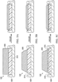
- Figures 5A-5C are schematic diagrams illustrating additional details that may be associated with some example embodiments of the tissue interface 120.
- the tissue interface 120 may comprise more than one component or layer, such as the bi-layer wound insert of Figure 5A and Figure 5B .
- the tissue interface 120 may include a manifold 505 and a biopolymer layer 510, which can also be referred to as a base biopolymer layer 510, coupled to the manifold 505.
- the biopolymer layer 510 may be in direct contact or indirect contact with the manifold 505.
- the biopolymer layer 510 is separable from the manifold 505.
- the biopolymer layer 510 may comprise a biological material selected from the group consisting of heparin, collagen, gelatin, hyaluronic acid, chitosan, cellulose, a cellulose derivative, alginate, fibrin, silk, carrageenan, chondroitin sulfate, agarose, keratin, dextran, keratan sulfate, heparan sulfate, fibronectin, laminin, and a combination thereof.
- a biological material selected from the group consisting of heparin, collagen, gelatin, hyaluronic acid, chitosan, cellulose, a cellulose derivative, alginate, fibrin, silk, carrageenan, chondroitin sulfate, agarose, keratin, dextran, keratan sulfate, heparan sulfate, fibronectin, laminin, and a combination thereof.
- the biopolymer layer 510 comprises collagen.
- suitable collagens include, but are not limited to native collagens, such as Types I, II and/or III native collagens, atelopeptide collagens, partially hydrolyzed collagens, such as gelatin, regenerated collagen and combinations thereof.
- the collagen may be present in any suitable amount, e.g., based on total weight of the biopolymer 510, collagen may be present in an amount ⁇ about 25 wt%, ⁇ about 30 wt%, ⁇ about 35 wt%, ⁇ about 40 wt%, ⁇ about 45 wt%, ⁇ about 50 wt%, ⁇ about 55 wt%, ⁇ about 60 wt%, ⁇ about 65 wt%, ⁇ about 70 wt%, ⁇ about 75 wt%, or ⁇ about 80 wt%.
- collagen may present, based on total weight of the biopolymer 510, in amount of about 25 wt% to about 80 wt%, about 35 wt% to about 75 wt%, about 40 wt% to about 70 wt%, about 45 wt% to about 65 wt%, or about 50 wt% to about 60 wt%.
- the biopolymer 510 may further comprise an anionic polysaccharide.
- the anionic polysaccharide may be substantially insoluble in water at pH 7. Additionally or alternatively, the anionic polysaccharide may have a molecular weight greater than about 20,000, more preferably greater than about 50,000.
- the anionic polysaccharide may be in the form of a film, or fibers having a length greater than 1 mm.
- Suitable anionic polysaccharides include, but are not limited to, polycarboxylates, alginates, hyaluronates, pectins, carrageenans, xanthan gums, sulfated dextrans, cellulose derivatives, such as carboxymethyl celluloses, and oxidized celluloses.
- oxidized cellulose refers to any material produced by the oxidation of cellulose, for example with dinitrogen tetroxide. Such oxidation converts primary alcohol groups on the saccharide residues to carboxylic acid groups, forming uronic acid residues within the cellulose chain.
- oxidized cellulose is biodegradable and resorbable or bioresorbable under physiological conditions.
- the biopolymer described herein may be resorbable or bioresorbable.
- resorbable or “bioresorbable” are synonymous and refer to the ability of at least a portion of a material to disintegrate, degrade, or dissolve upon exposure to physiological fluids or processes such that at least a portion of the material may be absorbed or assimilated, for example, at a tissue site or in vivo in a mammalian body. Resorbability or bioresorbability may be exhibited as a result of a chemical process or condition, a physical process or condition, or combinations thereof.
- oxidized cellulose present in the biopolymer layer 510 may be oxidized regenerated cellulose (ORC), which may be prepared by oxidation of a regenerated cellulose, such as rayon. It has been known that ORC has haemostatic properties. ORC has been available as a haemostatic fabric called SURGICEL ® (Johnson & Johnson Medical, Inc.) since 1950. This product may be produced by the oxidation of a knitted rayon material.
- ORC oxidized regenerated cellulose
- the anionic polysaccharide may be present in the biopolymer layer 510 in any suitable amount, e.g., based on total weight of the biopolymer layer 510, an anionic polysaccharide (e.g., ORC) may be present in an amount ⁇ about 15 wt%, ⁇ about 20 wt%, ⁇ about 25 wt%, ⁇ about 30 wt%, ⁇ about 35 wt%, ⁇ about 40 wt%, ⁇ about 45 wt%, ⁇ about 50 wt%, ⁇ about 55 wt%, ⁇ about 60 wt%, ⁇ about 65 wt%, or ⁇ about 70 wt%.
- ORC an anionic polysaccharide
- an anionic polysaccharide e.g., ORC
- ORC an anionic polysaccharide
- an anionic polysaccharide may be present in the biopolymer layer 510, based on total weight of the biopolymer layer 510, in amount of about 15 wt% to about 70 wt%, about 20 wt% to about 65 wt%, about 25 wt% to about 65 wt%, about 30 wt% to about 60 wt%, about 35 wt% to about 55 wt%, or about 40 wt% to about 50 wt%.
- ORC an anionic polysaccharide
- the biopolymer layer 510 may comprise collagen and an anionic polysaccharide, such as ORC.
- ORC an anionic polysaccharide
- the biopolymer layer 510 may comprise a lower density combination of collagen and ORC, of about 0.01 g/cm 3 , found in PROMOGRAN TM Matrix Wound Dressing (available from Acelity L.P. Inc. of San Antonio, Texas).
- the biopolymer layer 510 may comprise a higher density combination of collagen and an anioinic polysaccharide, such as ORC, of about 0.02 g/cm 3 , about 0.03 g/cm 3 , about 0.04 g/cm 3 , about 0.05 g/cm 3 , about 0.06 g/cm 3 , about 0.7 g/cm 3 , particularly about 0.4 g/cm 3 .
- the higher density combination of collagen and an anionic polysaccharide, such as ORC can range from about 0.02 g/cm 3 to about 0.07 g/cm 3 or about 0.03 g/cm 3 to about 0.06 g/cm 3 .
- the biopolymer layer 510 may further comprise an antimicrobial agent.
- suitable antimicrobial agents present in the biopolymer layer include, but are not limited to, organic acids such as carboxylic acids, silver, gold, zinc, copper, polyhexamethylene biguanide (PHMB), iodine and combinations thereof.
- exemplary carboxylic acids include, but are not limited to ascorbic acid (e.g., (R)-3,4-dihydroxy-5-((S)-1,2-dihydroxyethyl)furan-2(5H)-one or Vitamin C), formic acid, gluconic acid, lactic acid, oxalic acid, tartaric acid, peroxy-pyruvic acid, and combinations thereof.
- carboxylic acids include, but are not limited, to citric acid and acetic acid (i.e., ethanoic acid).
- the antimicrobial agent present in the biopolymer layer 510 may be citric acid.
- the antimicrobial agent e.g., citric acid
- the antimicrobial agent such as citric acid
- the antimicrobial agent may be present in a concentration ⁇ about 200 mM. Additionally or alternatively, the antimicrobial agent may be present in a concentration about 15 mM to about 650 mM, about 20 mM to about 500 mM, about 20 mM to about 400 mM, about 50 mM to about 650 mM, about 50 mM to about 500 mM, about 50 mM to about 400 mM, about 75 mM to about 650 mM, about 75 mM to about 500 mM, about 75 mM to about 400 mM, about 100 mM to about 650 mM, about 100 mM to about 500 mM, or about 100 mM to about 400 mM.
- the biopolymer layer 510 may comprise a metal, for example silver, which may be used as a further antimicrobial agent.
- the metal may be present in metallic form, in ionic form (e.g., a silver salt), or both.
- silver may be present in combination with one or more additional metals, for example, gold, platinum, ferro-manganese, copper, zinc, or a combination thereof.
- the metal, particularly, silver may confer antimicrobial properties to the biopolymer layer 510 and in sufficiently lower concentrations, e.g., about 0.10 wt% to about 3.0 wt%, the silver may not cause cytotoxicity in a wound or at a tissue site.
- the metal may be present as a complex of the anionic polysaccharide and the metal, for example, as an ORC-silver complex.
- the term "complex” refers to an intimate mixture at the molecular scale, preferably with ionic or covalent bonding between the metal (e.g., silver) and the polysaccharide (e.g., ORC).
- the complex may comprise a salt formed between the anionic polysaccharide and Ag+, but it may also comprise silver clusters and/or colloidal silver metal, for example produced by exposure of the complex to light.
- an anionic polysaccharide e.g., ORC
- a silver salt solution may be an aqueous solution and the solution may be prepared in a quantity sufficient to provide the desired silver concentration in the resultant complex.
- the amount of silver in the complex may be from about 0.1% to about 50% by weight based on the weight of the anionic polysaccharide, particularly, from about 1% to about 40%, about 2% to about 30% by weight, and about 5% to about 25%.
- an anionic polysaccharide-metal complex (e.g. , ORC-silver complex) may be present in the biopolymer layer 510 in an amount ⁇ about 0.10 wt%, ⁇ about 0.50 wt%, ⁇ about 1.0 wt%, ⁇ about 2.0 wt%, ⁇ about 3.0 wt%, ⁇ about 4.0 wt%, ⁇ about 5.0 wt%, ⁇ about 6.0 wt%, ⁇ about 8.0 wt%, or ⁇ about 10 wt%.
- ORC-silver complex an anionic polysaccharide-metal complex
- an anionic polysaccharide-metal complex may be present in the biopolymer 510, based on total weight of the biopolymer 510, in amount of about 0.10 wt% to about 10 wt%, about 0.10 wt% to about 8.0 wt%, about 0.10 wt% to about 5.0 wt%, about 0.50 wt% to about 4.0 wt%, about 0.50 wt% to about 3.0 wt%, or about 0.50 wt% to about 2.0 wt%.
- ORC-silver complex an anionic polysaccharide-metal complex
- the biopolymer layer 510 comprises collagen, an anionic polysaccharide (e.g., ORC), and a metal (e.g., silver).
- an anionic polysaccharide e.g., ORC
- a metal e.g., silver
- the biopolymer layer 510 may comprise PROMOGRAN PRISMA TM Matrix (available from Acelity L.P. Inc of San Antonio, Texas) and, optionally, an antimicrobial agent (e.g., citric acid).
- the biopolymer layer 510 may comprise a synthetic polymer selected from the group consisting of polycaprolactone, polylactic acid, polyglycolic acid, polydioxanone, poly(lactic-co-glycolic acid), polyhydroxybutyrate, polyhydroxyvalerate and a combination thereof.
- the synthetic polymer may have a degradation rate that will allow for separation from the manifold 505 in a 7-10 day timeframe.
- the biopolymer layer 510 has a thickness of about 0.1 cm to about 5 cm, preferably about 0.5 cm to about 3 cm.
- the biopolymer layer 510 is configured to be in contact with the wound facing and non-wound facing side and at least a portion of the outer edges of the manifold 505.
- the biopolymer layer 510 can be configured to reduce or prevent the ingrowth of tissue into at least a portion of the outer edges of the manifold 505, for example, during wound therapy such as negative pressure wound therapy.
- the biopolymer layer 510 can be configured to cover or be in contact will the entire surface area of the outer edges of the manifold 505.
- the biopolymer layer 510 is configured to contact at least a portion (or all) of the outer edges of the manifold 505 only during wound therapy use, such as negative pressure wound therapy use.
- the shape and/or size of the manifold 505 and biopolymer layer 510 can be altered such that the biopolymer layer 510 collapses onto the edges of the manifold 505 under application of negative pressure, reducing the exposed surface area for any granulation tissue entrapment.
- the manifold 505 and the biopolymer layer 510 together can have a trapezoidal cross-section having an inclined angle from about 20 to about 85 degrees, preferably about 30 to about 45 degrees as shown in the examples of Figures 5B and 5C .
- the inclined cut can be made by any suitable cutting means, for example a rotary cutter, wire cutter, clicker press, and/or laser cutter.
- the inclined cut can also be further tuned by an end user at the time of use by means of scissors and/or surgical scalpels.
- the biopolymer layer 510 may have a longer length than the manifold 505 and/or a larger surface area than the manifold 505.
- the tissue interface 120 can be manufactured such that the manifold 505 is in contact with the biopolymer layer 510 for only a portion of the biopolymer layer 510 surface area.
- an 8cm x 8cm area of manifold 505 e.g. polyurethane foam
- an area of overlap between the manifold 505 and the biopolymer layer 510 is about 0.01 cm to about 5 cm, more preferably 0.1 cm to about 3 cm, and most preferably about 0.3 cm to about 1 cm.
- the biopolymer layer 510 can be configured as a wound contact layer to be in direct contact with a wound. As shown in the examples of Figures 5A-5C , the biopolymer layer 510 is in direct contact with tissue 520.
- the biopolymer layer 510 is present as a coating on at least one face of the manifold 505. Additionally or alternatively, the biopolymer layer 510 can substantially cover or be co-extensive with at least one face of the manifold 505 and cover one or more edges of the manifold 505 partially or completely.
- the biopolymer layer 510 may have a dry state compressibility index value, as calculated above, of about zero, about 1%, about 2%, about 3%, about 4%, about 5%, about 6%, about 7%, about 8%, about 9%, about 10%, about 15%, about 20%, about 25%, about 30% or about 35%. Additionally or alternatively, the biopolymer layer 510 may have a dry state compressibility index value of about zero to about 35%, or about 1% to about 30%, or about 1% to about 25%, or about 1% to about 20%, or about 2% to about 20%, or about 2% to about 15%, or about 3% to about 10%. In particular embodiments, the dry state compressibility index value of the biopolymer layer 510 may be about 7%.
- the biopolymer layer 510 may have a hydrated stated compressibility index value, as calculated above, of about 60%, about 65%, about 70%, about 75%, about 80%, about 85% or about 90%. Additionally or alternatively, the biopolymer layer 510 may have a hydrated state compressibility index value of about 65% to about 90%, or about 65% to about 85%, or about 65% to about 80%. In particular embodiments, the hydrated state compressibility index value of the biopolymer layer 510 may be about 73%.
- the manifold 505 may have a different compressibility than the biopolymer 510.
- a dressing provided herein may have a manifold 505 and a biopolymer layer 510 coupled to the manifold 505, wherein the manifold 505 can have a compressibility index value (in either the dry or hydrated state) greater than the dry state compressibility index value of the biopolymer layer 510.
- the manifold 505 can also have a lower compressibility index value (in either the dry or hydrated state) than the hydrated state compressibility index value of the biopolymer layer 510.
- the manifold 505 may have a greater compressibility index value (in either the dry or hydrated state) than the dry state compressibility index value of the biopolymer layer 510, such as 10%, 15%, 20%, 25% or even 30% greater than the dry state compressibility index value of the biopolymer layer 510.
- the biopolymer layer 510 has a lower dry state compressibility index value than the compressibility index value of the manifold 505 in either the dry or hydrated state.
- the dry state compressibility index of the biopolymer layer 510 may be 10%, 15%, 20%, 25% or even 30% lower than the compressibility index value of the manifold 505 in either the dry or hydrated state.
- the compressibility differences between the manifold 505 and the biopolymer layer 510 may allow differential volume change as a response to externally applied subatmospheric pressure.
- the uneven changes in volume may result in minimal edge area of exposed manifold 505 (e.g. polyurethane foam), whereas the height (and thus the edge area) of the biopolymer layer 510 remains relatively unchanged as shown in the examples of Figures 5A-5C .
- the difference in compressibility between the manifold 505 and the biopolymer layer 510 may minimize the exposed area around the edges of the manifold 505 resulting in minimal to no granulation tissue ingrowth and/or entrapment within the edges of the manifold 505.
- the minimal edges of exposed manifold 505 may limit potential tissue ingrowth and entrapment.
- the tissue interface 120 may comprise more than one biopolymer layer, for example, two or three distinct biopolymer layers.
- the tissue interface 120 can be considered multi-layered.
- a second or additional biopolymer layer 515 may be included in the tissue interface 120 as shown in Figure 5C .
- the second or additional biopolymer layer 515 (also referred to as an intermediate biopolymer) is interposed between the manifold 505 and the first or base biopolymer layer 510.
- the second or additional biopolymer layer 515 can be constructed with differential mechanical properties (e.g. different compressibility, stiffness, porosity, etc.) such that the second or additional biopolymer layer 515 collapses more quickly under negative pressure than the first or base biopolymer layer 510, resulting in limited exposed edges of the manifold 505 as shown in the example of Figure 5C .
- differential mechanical properties e.g. different compressibility, stiffness, porosity, etc.
- the second or additional biopolymer layer 515 may have a greater dry state compressibility index value than either or both of the manifold 505 and the first or base biopolymer layer 510.
- the dry state compressibility index value of the second biopolymer layer 515 may be 5%, 25% or even 50% greater than the dry state compressibility index value of the first biopolymer layer 510.
- the second or additional biopolymer layer 515 has a dry state compressibility index value in the range of zero to 50% and a hydrated state compressibility index value in the range of 80%-100%.
- the second or additional biopolymer layer 515 may comprise any of the biopolymer materials listed above, for example, a biological material selected from the group consisting of heparin, collagen, gelatin, hyaluronic acid, chitosan, cellulose, a cellulose derivative, alginate, fibrin, silk, carrageenan, chondroitin sulfate, agarose, keratin, dextran, keratan sulfate, heparan sulfate, fibronectin, laminin, and a combination thereof.
- a biological material selected from the group consisting of heparin, collagen, gelatin, hyaluronic acid, chitosan, cellulose, a cellulose derivative, alginate, fibrin, silk, carrageenan, chondroitin sulfate, agarose, keratin, dextran, keratan sulfate, heparan sulfate, fibronectin, laminin
- tissue interface 120 In addition to dressings and therapy systems comprising a tissues interface 120 (or a wound insert), also provided herein are methods to make and customize a tissue interface 120.
- methods of making a dressing comprising a tissue interface 120 may comprise contacting at least a portion of the manifold 505 with a biopolymer slurry in aqueous base; and freeze drying the manifold 505 and the biopolymer slurry to form the biopolymer layer 510.
- a biopolymer slurry can be prepared by forming a solution of biopolymer materials as described herein with an aqueous base, such as a 0.05M acetic acid solution.
- an aqueous base such as a 0.05M acetic acid solution.
- 0.1% to 5%, preferably 1.25% to 3%, of collagen powder can be mixed with a 0.05M acetic acid solution, or water, or a weak acid or base to form a slurry, and 0.1% to 5%, preferably 1.25% to 3%, of cellulose, such as ORC, can be added to the slurry and mixed.
- the manifold 505 can be brought into contact with the biopolymer slurry, and optionally, depressed into the biopolymer slurry.
- the combination of manifold 505 and biopolymer slurry can then be frozen at a temperature of about -70°C for a minimum of 30 minutes, and preferably in the range of about 12 to 24 hours.
- Once frozen the combination of the manifold 505 and the biopolymer slurry can be freeze dried to create the manifold 505 with the biopolymer layer 510 as a freeze dried sponge (which can also be referred to as a layer or sheet).
- Multiple tissue interfaces can be made from the same cast sheet, which can be cut out after freeze drying.
- the biopolymer layer 510 can be removably attached to the manifold 505.
- methods of making a dressing comprising a tissue interface 120 may comprise preparing and freeze drying a biopolymer slurry as described above to form the biopolymer layer 510 and then contacting at least a portion of the manifold 505 with the biopolymer layer 510.
- a series of text or symbols can be printed post-fabrication on the biopolymer layer 510.
- the text or symbols may be used to guide an end user about tissue interface 120 or wound insert placement direction in a wound bed.
- manifold 505 can also be manipulated to allow for customized compression, shape and size.
- the manifold 505 can be perforated. Perforating the manifold 505 can be performed before or after the biopolymer layer 510 is applied or contacted to the manifold 505, preferably before. Any suitable means can be used to perforate such as die cutting or slitting.
- the manifold 505 can have two or more partial cuts 605 and a base 615 as shown in the examples of Figure 6 and Figure 7.
- Figure 6 is a side view of an example tissue interface 120 having a manifold 505 and a biopolymer layer 510, wherein the biopolymer layer 510 has a larger surface area than the manifold 505.
- the partial cuts 605 do not go all the way through the manifold 505, thus the base 615 of the manifold 505 is still intact. Partial cuts 605 allow the manifold 505 to collapse in on itself and to provide one or more removable parts or partial pillars 610.
- the manifold 505 can be said to have a partial pillar configuration.
- FIG 7 is a top view of the example tissue interface 120 of Figure 6 .
- a partial pillar configuration allows an end user to remove one or more pillars 610 to increase the compression on one or more sides of tissue interface 120, and also to customize the size and shape of the tissue interface 120.
- Any suitable cutting means can be used for creating the partial pillars 610.
- hot wire, laser cutting, die cutting with limited force, or wire jet may be used.
- Cutting the manifold 505 to create the partial pillars 610 can be performed before or after the biopolymer layer 510 is applied or contacted to the manifold 505, preferably before.
- the manifold 505 can be partially cut in a spiral shape (spiral cut) as shown in the top view of Figure 8 to provide one or more removable parts to customize the size and shape of the manifold 505.
- One or more ends of the spiral cut can be removed from the manifold 505 to serve as a bridge landing pad.
- spiral end 805 can be removed and placed on intact skin adjacent a wound.
- a dressing interface such as a pad for receiving pressure (e.g. a SENSAT.R.A.C. TM Pad available from Kinetic Concepts, Inc. of San Antonio, Texas) can be applied to spiral end 805. Pressure can then be applied outside the wound to create a vacuum in the wound.
- spiral end 805 can be placed in a second wound and serve as a bridge to apply pressure to one or more wounds.
- spiral end 810 can also act as a bridge or bridge landing pad in a similar manner.
- the systems, apparatuses, and methods described herein may provide significant advantages.
- manifolding negative pressure through a porous dressing construct such as the tissue interface 120
- the construction and composition of the porous dressing construct can have an impact upon the clinical regimen.
- the granulation tissue can grow into the dressing construct and entrap portions of the dressing within the newly formed tissue.
- the tissue interface 120 described herein can reduce or prevent tissue ingrowth from the bottom and edges of a wound, which can improve both the wound healing process and patient comfort.
- Collagen powder Bovine dermis collagen source
- acetic acid solution 0.05M concentration
- acetic acid solution 0.05M concentration
- acetic acid solution 0.05M concentration
- acetic acid solution 0.05M concentration
- acetic acid solution 0.05M concentration
- acetic acid solution 0.05M concentration
- acetic acid solution 0.05M concentration
- acetic acid solution 0.05M concentration
- acetic acid solution 0.05M concentration
- acetic acid solution 0.05M concentration
- the material was slowly poured into square petri trays (10x10cm) with 62g material added to each tray.
- the process of application to the slurry mixture is sufficient to achieve a level of slurry integration into the foam material. There is no need to depress the foam material (unless greater integration between the materials is required).
- the resulting combination material is then frozen in a -70°C freezer to generate a polyurethane foam material with a frozen biopolymer sheet at the interface. Once frozen this material is then freeze dried to generate a polyurethane foam material with attached freeze dried sponge of collagen and oxidized regenerated cellulose ( ⁇ 4mm in thickness).
Landscapes
- Health & Medical Sciences (AREA)
- Public Health (AREA)
- Engineering & Computer Science (AREA)
- Veterinary Medicine (AREA)
- Life Sciences & Earth Sciences (AREA)
- Animal Behavior & Ethology (AREA)
- General Health & Medical Sciences (AREA)
- Heart & Thoracic Surgery (AREA)
- Chemical & Material Sciences (AREA)
- Hematology (AREA)
- Vascular Medicine (AREA)
- Biomedical Technology (AREA)
- Materials Engineering (AREA)
- Epidemiology (AREA)
- Anesthesiology (AREA)
- Dispersion Chemistry (AREA)
- Media Introduction/Drainage Providing Device (AREA)
Claims (15)
- Pansement destiné à être utilisé avec un traitement de plaie par pression négative comprenantun collecteur (505), le collecteur (505) présentant un côté faisant face à la plaie, un côté ne faisant pas face à la plaie opposé au côté faisant face à la plaie, et des bords externes entre les côtés faisant face à la plaie et ne faisant pas face à la plaie ; etune première couche de biopolymère (510) en contact avec le côté faisant face à la plaie et au moins une partie des bords externes du collecteur (505), la première couche de biopolymère (510) étant destinée à réduire ou prévenir la croissance de tissu dans ladite partie des bords externes pendant un traitement de plaie par pression négative.
- Pansement selon la revendication 1, dans lequel la première couche de biopolymère (510) vient en contact avec ladite partie des bords externes uniquement pendant un traitement de plaie par pression négative.
- Pansement selon la revendication 1 ou la revendication 2, dans lequel la première couche de biopolymère (510) est reliée au collecteur (505).
- Pansement selon l'une quelconque des revendications précédentes, dans lequel la première couche de biopolymère (510) est séparable du collecteur (505).
- Pansement selon l'une quelconque des revendications précédentes, dans lequel la première couche de biopolymère (510) comprend un matériau biologique choisi dans le groupe constitué par l'héparine, le collagène, la gélatine, l'acide hyaluronique, le chitosane, la cellulose, un dérivé de cellulose, l'alginate, la fibrine, la soie, le carraghénane, le sulfate de chondroïtine, l'agarose, la kératine, le dextrane, le sulfate de kératane, le sulfate d'héparane, la fibronectine, la laminine et une combinaison de ceux-ci.
- Pansement selon l'une quelconque des revendications précédentes, dans lequel la première couche de biopolymère (510) comprend un polymère synthétique choisi dans le groupe constitué par la polycaprolactone, l'acide polylactique, l'acide polyglycolique, le polydioxanone, l'acide poly(lactique-coglycolique) et le polyhydroxybutyrate, le polyhydoroxyvalérate ou une combinaison quelconque de ceux-ci.
- Pansement selon l'une quelconque des revendications précédentes, dans lequel la première couche de biopolymère (510) comprend du collagène ; et comprend également de la cellulose non régénérée oxydée et/ou de la cellulose régénérée oxydée.
- Pansement selon l'une quelconque des revendications précédentes, dans lequel la première couche de biopolymère (510) est perforée et/ou est imprimée avec du texte et/ou des symboles.
- Pansement selon l'une quelconque des revendications précédentes, dans lequel la première couche de biopolymère (510) a une épaisseur d'environ 0,1 cm à environ 5 cm, de préférence d'environ 0,5 cm à environ 3 cm.
- Pansement selon l'une quelconque des revendications précédentes, dans lequel la première couche de biopolymère (510) a une densité d'environ 0,01 g/cm3 à environ 0,06 g/cm3, de préférence d'environ 0,02 g/cm3 à environ 0,06 g/cm3.
- Pansement selon l'une quelconque des revendications précédentes, dans lequel le collecteur (505) comprend de la silicone, de l'alcool polyvinylique, une combinaison de ceux-ci, ou une mousse, de préférence une mousse polymère, et plus préférablement une mousse d'éther de polyuréthane ou d'ester de polyuréthane.
- Pansement selon l'une quelconque des revendications précédentes, dans lequel le collecteur (505) a une épaisseur d'environ 0,5 cm à environ 8 cm, de préférence d'environ 1 cm à environ 3 cm.
- Pansement selon l'une quelconque des revendications précédentes, dans lequel une zone de chevauchement entre le collecteur (505) et la première couche de biopolymère (510) est d'environ 0,01 cm à environ 3 cm, de préférence d'environ 0,3 cm à environ 1 cm.
- Pansement selon l'une quelconque des revendications précédentes, dans lequel le collecteur (505) et la première couche de biopolymère (510) ont ensemble une section transversale trapézoïdale ayant un angle incliné d'environ 20 à environ 85 degrés, de préférence d'environ 30 à environ 45 degrés.
- Pansement selon l'une quelconque des revendications précédentes, dans lequel le collecteur (505) est perforé ou présente une ou plusieurs découpes partielles.
Applications Claiming Priority (2)
| Application Number | Priority Date | Filing Date | Title |
|---|---|---|---|
| US201862723837P | 2018-08-28 | 2018-08-28 | |
| PCT/US2019/038273 WO2020046443A1 (fr) | 2018-08-28 | 2019-06-20 | Pansements destinés à une interpénétration tissulaire réduite |
Publications (2)
| Publication Number | Publication Date |
|---|---|
| EP3843678A1 EP3843678A1 (fr) | 2021-07-07 |
| EP3843678B1 true EP3843678B1 (fr) | 2023-07-26 |
Family
ID=67185746
Family Applications (1)
| Application Number | Title | Priority Date | Filing Date |
|---|---|---|---|
| EP19736897.0A Active EP3843678B1 (fr) | 2018-08-28 | 2019-06-20 | Pansements destinés à une interpénétration tissulaire réduite |
Country Status (3)
| Country | Link |
|---|---|
| US (2) | US11752039B2 (fr) |
| EP (1) | EP3843678B1 (fr) |
| WO (1) | WO2020046443A1 (fr) |
Families Citing this family (23)
| Publication number | Priority date | Publication date | Assignee | Title |
|---|---|---|---|---|
| GB0808376D0 (en) | 2008-05-08 | 2008-06-18 | Bristol Myers Squibb Co | Wound dressing |
| GB0817796D0 (en) | 2008-09-29 | 2008-11-05 | Convatec Inc | wound dressing |
| GB201020236D0 (en) | 2010-11-30 | 2011-01-12 | Convatec Technologies Inc | A composition for detecting biofilms on viable tissues |
| CA2819475C (fr) | 2010-12-08 | 2019-02-12 | Convatec Technologies Inc. | Systeme integre pour evaluer des exsudats de plaie |
| WO2012078724A1 (fr) | 2010-12-08 | 2012-06-14 | Convatec Technologies Inc. | Appareil et procédé d'application d'une pression sur une plaie |
| US9526816B2 (en) | 2010-12-08 | 2016-12-27 | Convatec Technologies Inc. | Wound exudate monitor accessory |
| GB201115182D0 (en) | 2011-09-02 | 2011-10-19 | Trio Healthcare Ltd | Skin contact material |
| GB2497406A (en) | 2011-11-29 | 2013-06-12 | Webtec Converting Llc | Dressing with a perforated binder layer |
| EP2935688A2 (fr) | 2012-12-20 | 2015-10-28 | ConvaTec Technologies Inc. | Traitement de fibres cellulosiques chimiquement modifiées |
| AU2017243601A1 (en) | 2016-03-30 | 2018-11-22 | Acib Gmbh | Detecting microbial infection in wounds |
| CN109310528B (zh) | 2016-03-30 | 2021-07-20 | 康沃特克科技公司 | 检测伤口中的微生物感染 |
| GB201608099D0 (en) | 2016-05-09 | 2016-06-22 | Convatec Technologies Inc | Negative pressure wound dressing |
| TW201805034A (zh) | 2016-07-08 | 2018-02-16 | 美商康瓦鐵克科技股份有限公司 | 彈性的負壓系統 |
| MX2019000234A (es) | 2016-07-08 | 2019-09-06 | Convatec Technologies Inc | Aparato de recoleccion de fluidos. |
| EP3481360B1 (fr) | 2016-07-08 | 2022-03-09 | ConvaTec Technologies Inc. | Détecteur de l'écoulement d'un liquide. |
| US12161792B2 (en) | 2017-11-16 | 2024-12-10 | Convatec Limited | Fluid collection apparatus |
| US11752039B2 (en) * | 2018-08-28 | 2023-09-12 | Systagenix Wound Management, Limited | Dressings for reduced tissue ingrowth |
| SG11202112292QA (en) | 2019-06-03 | 2021-12-30 | Convatec Ltd | Methods and devices to disrupt and contain pathogens |
| EP4031082B1 (fr) * | 2019-09-05 | 2023-06-21 | KCI Licensing, Inc. | Interfaces de tissu à port à long terme pour pansements de thérapie à pression négative à force de fermeture élevée |
| US11331221B2 (en) | 2019-12-27 | 2022-05-17 | Convatec Limited | Negative pressure wound dressing |
| US11771819B2 (en) | 2019-12-27 | 2023-10-03 | Convatec Limited | Low profile filter devices suitable for use in negative pressure wound therapy systems |
| WO2022101719A1 (fr) * | 2020-11-12 | 2022-05-19 | Kci Manufacturing Unlimited Company | Pansement pour thérapie par pression négative à profondeur extensible |
| WO2026015085A1 (fr) * | 2024-07-12 | 2026-01-15 | Agency For Science, Technology And Research | Structure composite et procédés associés |
Family Cites Families (160)
| Publication number | Priority date | Publication date | Assignee | Title |
|---|---|---|---|---|
| US1355846A (en) | 1920-02-06 | 1920-10-19 | David A Rannells | Medical appliance |
| US2547758A (en) | 1949-01-05 | 1951-04-03 | Wilmer B Keeling | Instrument for treating the male urethra |
| US2632443A (en) | 1949-04-18 | 1953-03-24 | Eleanor P Lesher | Surgical dressing |
| GB692578A (en) | 1949-09-13 | 1953-06-10 | Minnesota Mining & Mfg | Improvements in or relating to drape sheets for surgical use |
| US2682873A (en) | 1952-07-30 | 1954-07-06 | Johnson & Johnson | General purpose protective dressing |
| NL189176B (nl) | 1956-07-13 | 1900-01-01 | Hisamitsu Pharmaceutical Co | Pleister op basis van een synthetische rubber. |
| US2969057A (en) | 1957-11-04 | 1961-01-24 | Brady Co W H | Nematodic swab |
| US3066672A (en) | 1960-09-27 | 1962-12-04 | Jr William H Crosby | Method and apparatus for serial sampling of intestinal juice |
| US3367332A (en) | 1965-08-27 | 1968-02-06 | Gen Electric | Product and process for establishing a sterile area of skin |
| US3520300A (en) | 1967-03-15 | 1970-07-14 | Amp Inc | Surgical sponge and suction device |
| US3568675A (en) | 1968-08-30 | 1971-03-09 | Clyde B Harvey | Fistula and penetrating wound dressing |
| US3682180A (en) | 1970-06-08 | 1972-08-08 | Coilform Co Inc | Drain clip for surgical drain |
| BE789293Q (fr) | 1970-12-07 | 1973-01-15 | Parke Davis & Co | Pansement medico-chirugical pour brulures et lesions analogues |
| US3826254A (en) | 1973-02-26 | 1974-07-30 | Verco Ind | Needle or catheter retaining appliance |
| DE2527706A1 (de) | 1975-06-21 | 1976-12-30 | Hanfried Dr Med Weigand | Einrichtung zum einleiten von kontrastmittel in einen kuenstlichen darmausgang |
| DE2640413C3 (de) | 1976-09-08 | 1980-03-27 | Richard Wolf Gmbh, 7134 Knittlingen | Katheter-Überwachungsgerät |
| NL7710909A (nl) | 1976-10-08 | 1978-04-11 | Smith & Nephew | Samengestelde hechtstrook. |
| GB1562244A (en) | 1976-11-11 | 1980-03-05 | Lock P M | Wound dressing materials |
| US4080970A (en) | 1976-11-17 | 1978-03-28 | Miller Thomas J | Post-operative combination dressing and internal drain tube with external shield and tube connector |
| US4139004A (en) | 1977-02-17 | 1979-02-13 | Gonzalez Jr Harry | Bandage apparatus for treating burns |
| US4184510A (en) | 1977-03-15 | 1980-01-22 | Fibra-Sonics, Inc. | Valued device for controlling vacuum in surgery |
| US4165748A (en) | 1977-11-07 | 1979-08-28 | Johnson Melissa C | Catheter tube holder |
| US4256109A (en) | 1978-07-10 | 1981-03-17 | Nichols Robert L | Shut off valve for medical suction apparatus |
| SE414994B (sv) | 1978-11-28 | 1980-09-01 | Landstingens Inkopscentral | Venkateterforband |
| WO1980001139A1 (fr) | 1978-12-06 | 1980-06-12 | Svedman Paul | Dispositif de traitement des tissus, par exemple de la peau |
| US4266545A (en) | 1979-04-06 | 1981-05-12 | Moss James P | Portable suction device for collecting fluids from a closed wound |
| US4284079A (en) | 1979-06-28 | 1981-08-18 | Adair Edwin Lloyd | Method for applying a male incontinence device |
| US4261363A (en) | 1979-11-09 | 1981-04-14 | C. R. Bard, Inc. | Retention clips for body fluid drains |
| US4569348A (en) | 1980-02-22 | 1986-02-11 | Velcro Usa Inc. | Catheter tube holder strap |
| ATE14835T1 (de) | 1980-03-11 | 1985-08-15 | Schmid Eduard | Hauttransplantations-druckverband. |
| US4297995A (en) | 1980-06-03 | 1981-11-03 | Key Pharmaceuticals, Inc. | Bandage containing attachment post |
| US4333468A (en) | 1980-08-18 | 1982-06-08 | Geist Robert W | Mesentery tube holder apparatus |
| US4465485A (en) | 1981-03-06 | 1984-08-14 | Becton, Dickinson And Company | Suction canister with unitary shut-off valve and filter features |
| US4392853A (en) | 1981-03-16 | 1983-07-12 | Rudolph Muto | Sterile assembly for protecting and fastening an indwelling device |
| US4373519A (en) | 1981-06-26 | 1983-02-15 | Minnesota Mining And Manufacturing Company | Composite wound dressing |
| US4392858A (en) | 1981-07-16 | 1983-07-12 | Sherwood Medical Company | Wound drainage device |
| US4419097A (en) | 1981-07-31 | 1983-12-06 | Rexar Industries, Inc. | Attachment for catheter tube |
| AU550575B2 (en) | 1981-08-07 | 1986-03-27 | Richard Christian Wright | Wound drainage device |
| SE429197B (sv) | 1981-10-14 | 1983-08-22 | Frese Nielsen | Anordning for behandling av sar |
| DE3146266A1 (de) | 1981-11-21 | 1983-06-01 | B. Braun Melsungen Ag, 3508 Melsungen | Kombinierte vorrichtung fuer eine medizinische saugdrainage |
| US4551139A (en) | 1982-02-08 | 1985-11-05 | Marion Laboratories, Inc. | Method and apparatus for burn wound treatment |
| US4475909A (en) | 1982-05-06 | 1984-10-09 | Eisenberg Melvin I | Male urinary device and method for applying the device |
| EP0100148B1 (fr) | 1982-07-06 | 1986-01-08 | Dow Corning Limited | Pansement médico-chirurgical et son procédé de production |
| NZ206837A (en) | 1983-01-27 | 1986-08-08 | Johnson & Johnson Prod Inc | Thin film adhesive dressing:backing material in three sections |
| US4548202A (en) | 1983-06-20 | 1985-10-22 | Ethicon, Inc. | Mesh tissue fasteners |
| US4540412A (en) | 1983-07-14 | 1985-09-10 | The Kendall Company | Device for moist heat therapy |
| US4543100A (en) | 1983-11-01 | 1985-09-24 | Brodsky Stuart A | Catheter and drain tube retainer |
| US4525374A (en) | 1984-02-27 | 1985-06-25 | Manresa, Inc. | Treating hydrophobic filters to render them hydrophilic |
| CA1286177C (fr) | 1984-05-03 | 1991-07-16 | Smith And Nephew Associated Companies Plc | Pansement adhesif |
| US4897081A (en) | 1984-05-25 | 1990-01-30 | Thermedics Inc. | Percutaneous access device |
| US5215522A (en) | 1984-07-23 | 1993-06-01 | Ballard Medical Products | Single use medical aspirating device and method |
| GB8419745D0 (en) | 1984-08-02 | 1984-09-05 | Smith & Nephew Ass | Wound dressing |
| US4872450A (en) | 1984-08-17 | 1989-10-10 | Austad Eric D | Wound dressing and method of forming same |
| US4826494A (en) | 1984-11-09 | 1989-05-02 | Stryker Corporation | Vacuum wound drainage system |
| US4655754A (en) | 1984-11-09 | 1987-04-07 | Stryker Corporation | Vacuum wound drainage system and lipids baffle therefor |
| US4605399A (en) | 1984-12-04 | 1986-08-12 | Complex, Inc. | Transdermal infusion device |
| US5037397A (en) | 1985-05-03 | 1991-08-06 | Medical Distributors, Inc. | Universal clamp |
| US4640688A (en) | 1985-08-23 | 1987-02-03 | Mentor Corporation | Urine collection catheter |
| US4710165A (en) | 1985-09-16 | 1987-12-01 | Mcneil Charles B | Wearable, variable rate suction/collection device |
| US4758220A (en) | 1985-09-26 | 1988-07-19 | Alcon Laboratories, Inc. | Surgical cassette proximity sensing and latching apparatus |
| US4733659A (en) | 1986-01-17 | 1988-03-29 | Seton Company | Foam bandage |
| WO1987004626A1 (fr) | 1986-01-31 | 1987-08-13 | Osmond, Roger, L., W. | Systeme de succion pour drainage de blessures et drainage gastro-intestinal |
| US4838883A (en) | 1986-03-07 | 1989-06-13 | Nissho Corporation | Urine-collecting device |
| JPS62281965A (ja) | 1986-05-29 | 1987-12-07 | テルモ株式会社 | カテ−テルおよびカテ−テル用固定部材 |
| GB8621884D0 (en) | 1986-09-11 | 1986-10-15 | Bard Ltd | Catheter applicator |
| GB2195255B (en) | 1986-09-30 | 1991-05-01 | Vacutec Uk Limited | Apparatus for vacuum treatment of an epidermal surface |
| US4743232A (en) | 1986-10-06 | 1988-05-10 | The Clinipad Corporation | Package assembly for plastic film bandage |
| DE3634569A1 (de) | 1986-10-10 | 1988-04-21 | Sachse Hans E | Kondomkatheter, ein harnroehrenkatheter zur verhinderung von aufsteigenden infektionen |
| JPS63135179A (ja) | 1986-11-26 | 1988-06-07 | 立花 俊郎 | 薬物の経皮投与具 |
| GB8628564D0 (en) | 1986-11-28 | 1987-01-07 | Smiths Industries Plc | Anti-foaming agent suction apparatus |
| GB8706116D0 (en) | 1987-03-14 | 1987-04-15 | Smith & Nephew Ass | Adhesive dressings |
| US4787888A (en) | 1987-06-01 | 1988-11-29 | University Of Connecticut | Disposable piezoelectric polymer bandage for percutaneous delivery of drugs and method for such percutaneous delivery (a) |
| US4863449A (en) | 1987-07-06 | 1989-09-05 | Hollister Incorporated | Adhesive-lined elastic condom cathether |
| US5176663A (en) | 1987-12-02 | 1993-01-05 | Pal Svedman | Dressing having pad with compressibility limiting elements |
| US4906240A (en) | 1988-02-01 | 1990-03-06 | Matrix Medica, Inc. | Adhesive-faced porous absorbent sheet and method of making same |
| US4985019A (en) | 1988-03-11 | 1991-01-15 | Michelson Gary K | X-ray marker |
| GB8812803D0 (en) | 1988-05-28 | 1988-06-29 | Smiths Industries Plc | Medico-surgical containers |
| US4919654A (en) | 1988-08-03 | 1990-04-24 | Kalt Medical Corporation | IV clamp with membrane |
| US5000741A (en) | 1988-08-22 | 1991-03-19 | Kalt Medical Corporation | Transparent tracheostomy tube dressing |
| DE69017479T2 (de) | 1989-01-16 | 1995-07-13 | Roussel Uclaf | Azabicycloheptenderivate und ihre Salze, Verfahren zu ihrer Herstellung, ihre Verwendung als Arzneimittel und diese enthaltende Zubereitungen. |
| GB8906100D0 (en) | 1989-03-16 | 1989-04-26 | Smith & Nephew | Laminates |
| US4969880A (en) | 1989-04-03 | 1990-11-13 | Zamierowski David S | Wound dressing and treatment method |
| US5100396A (en) | 1989-04-03 | 1992-03-31 | Zamierowski David S | Fluidic connection system and method |
| US5261893A (en) | 1989-04-03 | 1993-11-16 | Zamierowski David S | Fastening system and method |
| US5527293A (en) | 1989-04-03 | 1996-06-18 | Kinetic Concepts, Inc. | Fastening system and method |
| JP2719671B2 (ja) | 1989-07-11 | 1998-02-25 | 日本ゼオン株式会社 | 創傷被覆材 |
| US5358494A (en) | 1989-07-11 | 1994-10-25 | Svedman Paul | Irrigation dressing |
| US5232453A (en) | 1989-07-14 | 1993-08-03 | E. R. Squibb & Sons, Inc. | Catheter holder |
| GB2235877A (en) | 1989-09-18 | 1991-03-20 | Antonio Talluri | Closed wound suction apparatus |
| US5134994A (en) | 1990-02-12 | 1992-08-04 | Say Sam L | Field aspirator in a soft pack with externally mounted container |
| US5092858A (en) | 1990-03-20 | 1992-03-03 | Becton, Dickinson And Company | Liquid gelling agent distributor device |
| US5149331A (en) | 1991-05-03 | 1992-09-22 | Ariel Ferdman | Method and device for wound closure |
| US5278100A (en) | 1991-11-08 | 1994-01-11 | Micron Technology, Inc. | Chemical vapor deposition technique for depositing titanium silicide on semiconductor wafers |
| US7198046B1 (en) | 1991-11-14 | 2007-04-03 | Wake Forest University Health Sciences | Wound treatment employing reduced pressure |
| US5645081A (en) | 1991-11-14 | 1997-07-08 | Wake Forest University | Method of treating tissue damage and apparatus for same |
| US5636643A (en) | 1991-11-14 | 1997-06-10 | Wake Forest University | Wound treatment employing reduced pressure |
| US5279550A (en) | 1991-12-19 | 1994-01-18 | Gish Biomedical, Inc. | Orthopedic autotransfusion system |
| US5167613A (en) | 1992-03-23 | 1992-12-01 | The Kendall Company | Composite vented wound dressing |
| FR2690617B1 (fr) | 1992-04-29 | 1994-06-24 | Cbh Textile | Pansement adhesif transparent. |
| DE4306478A1 (de) | 1993-03-02 | 1994-09-08 | Wolfgang Dr Wagner | Drainagevorrichtung, insbesondere Pleuradrainagevorrichtung, und Drainageverfahren |
| US6241747B1 (en) | 1993-05-03 | 2001-06-05 | Quill Medical, Inc. | Barbed Bodily tissue connector |
| US5342376A (en) | 1993-05-03 | 1994-08-30 | Dermagraphics, Inc. | Inserting device for a barbed tissue connector |
| US5344415A (en) | 1993-06-15 | 1994-09-06 | Deroyal Industries, Inc. | Sterile system for dressing vascular access site |
| US5437651A (en) | 1993-09-01 | 1995-08-01 | Research Medical, Inc. | Medical suction apparatus |
| US5549584A (en) | 1994-02-14 | 1996-08-27 | The Kendall Company | Apparatus for removing fluid from a wound |
| US5484896A (en) * | 1994-03-24 | 1996-01-16 | The Procter & Gamble Company | Esterified high lignin content cellulosic fibers |
| US5607388A (en) | 1994-06-16 | 1997-03-04 | Hercules Incorporated | Multi-purpose wound dressing |
| US5556375A (en) | 1994-06-16 | 1996-09-17 | Hercules Incorporated | Wound dressing having a fenestrated base layer |
| US5664270A (en) | 1994-07-19 | 1997-09-09 | Kinetic Concepts, Inc. | Patient interface system |
| DK1219311T3 (da) | 1994-08-22 | 2004-08-30 | Kci Licensing Inc | Beholder |
| DE29504378U1 (de) | 1995-03-15 | 1995-09-14 | MTG Medizinisch, technische Gerätebau GmbH, 66299 Friedrichsthal | Elektronisch geregelte Niedervakuumpumpe für die Thorax- und Wunddrainage |
| GB9523253D0 (en) | 1995-11-14 | 1996-01-17 | Mediscus Prod Ltd | Portable wound treatment apparatus |
| US6135116A (en) | 1997-07-28 | 2000-10-24 | Kci Licensing, Inc. | Therapeutic method for treating ulcers |
| GB9719520D0 (en) | 1997-09-12 | 1997-11-19 | Kci Medical Ltd | Surgical drape and suction heads for wound treatment |
| AU755496B2 (en) | 1997-09-12 | 2002-12-12 | Kci Licensing, Inc. | Surgical drape and suction head for wound treatment |
| US6071267A (en) | 1998-02-06 | 2000-06-06 | Kinetic Concepts, Inc. | Medical patient fluid management interface system and method |
| US6488643B1 (en) | 1998-10-08 | 2002-12-03 | Kci Licensing, Inc. | Wound healing foot wrap |
| US6287316B1 (en) | 1999-03-26 | 2001-09-11 | Ethicon, Inc. | Knitted surgical mesh |
| US7799004B2 (en) | 2001-03-05 | 2010-09-21 | Kci Licensing, Inc. | Negative pressure wound treatment apparatus and infection identification system and method |
| US6856821B2 (en) | 2000-05-26 | 2005-02-15 | Kci Licensing, Inc. | System for combined transcutaneous blood gas monitoring and vacuum assisted wound closure |
| US6991643B2 (en) | 2000-12-20 | 2006-01-31 | Usgi Medical Inc. | Multi-barbed device for retaining tissue in apposition and methods of use |
| WO2001062328A1 (fr) | 2000-02-24 | 2001-08-30 | Venetec International, Inc. | Systeme polyvalent servant a fixer un catheter |
| US7700819B2 (en) * | 2001-02-16 | 2010-04-20 | Kci Licensing, Inc. | Biocompatible wound dressing |
| US6540705B2 (en) | 2001-02-22 | 2003-04-01 | Core Products International, Inc. | Ankle brace providing upper and lower ankle adjustment |
| US20050137512A1 (en) * | 2003-12-23 | 2005-06-23 | Campbell Todd D. | Wound dressing and method for controlling severe, life-threatening bleeding |
| US7846141B2 (en) | 2002-09-03 | 2010-12-07 | Bluesky Medical Group Incorporated | Reduced pressure treatment system |
| GB0224986D0 (en) | 2002-10-28 | 2002-12-04 | Smith & Nephew | Apparatus |
| US10363344B2 (en) * | 2002-12-31 | 2019-07-30 | Kci Licensing, Inc. | Externally-applied patient interface system and method with a controlled region for implanted or buried bio-reactor |
| GB0325120D0 (en) | 2003-10-28 | 2003-12-03 | Smith & Nephew | Apparatus with actives |
| GB0325126D0 (en) | 2003-10-28 | 2003-12-03 | Smith & Nephew | Apparatus with heat |
| US7909805B2 (en) | 2004-04-05 | 2011-03-22 | Bluesky Medical Group Incorporated | Flexible reduced pressure treatment appliance |
| US8529548B2 (en) | 2004-04-27 | 2013-09-10 | Smith & Nephew Plc | Wound treatment apparatus and method |
| US20080208171A1 (en) | 2007-02-23 | 2008-08-28 | Argenta Louis C | Device and method for removing edema |
| WO2008104609A1 (fr) * | 2007-03-01 | 2008-09-04 | Coloplast A/S | Éléments de distribution de pression pour traitement par pression négative |
| US20090177133A1 (en) * | 2008-01-04 | 2009-07-09 | Kristine Kieswetter | Reduced pressure dressing coated with biomolecules |
| US9782300B2 (en) | 2008-02-01 | 2017-10-10 | Kci Licensing, Inc. | Fiber-microsphere bioresorbable composite scaffold for wound healing |
| US8021347B2 (en) | 2008-07-21 | 2011-09-20 | Tyco Healthcare Group Lp | Thin film wound dressing |
| US8007481B2 (en) | 2008-07-17 | 2011-08-30 | Tyco Healthcare Group Lp | Subatmospheric pressure mechanism for wound therapy system |
| JP5406283B2 (ja) * | 2008-05-30 | 2014-02-05 | ケーシーアイ ライセンシング インコーポレイテッド | 湾曲した身体部分に用いる減圧・圧縮システムおよび装置 |
| EP2303353B1 (fr) | 2008-06-12 | 2018-01-10 | Ramot at Tel-Aviv University Ltd. | Dispositifs médicaux à élution de médicament |
| US8216198B2 (en) | 2009-01-09 | 2012-07-10 | Tyco Healthcare Group Lp | Canister for receiving wound exudate in a negative pressure therapy system |
| US8251979B2 (en) | 2009-05-11 | 2012-08-28 | Tyco Healthcare Group Lp | Orientation independent canister for a negative pressure wound therapy device |
| ES2829956T3 (es) * | 2008-10-02 | 2021-06-02 | Lrr & D Ltd | Apósito para heridas en capa de interfaz |
| US8708984B2 (en) | 2008-12-24 | 2014-04-29 | Kci Licensing, Inc. | Reduced-pressure wound treatment systems and methods employing manifold structures |
| US8632512B2 (en) * | 2010-04-09 | 2014-01-21 | Kci Licensing, Inc. | Apparatuses, methods, and compositions for the treatment and prophylaxis of chronic wounds |
| US20120107366A1 (en) | 2010-11-03 | 2012-05-03 | Mbiya Kapiamba | Block Copolymer Systems and Their Use in Medical Devices |
| TWI465263B (zh) | 2010-12-10 | 2014-12-21 | Ind Tech Res Inst | 醫用敷料及使用該敷料之負壓治療裝置 |
| JP2012203784A (ja) * | 2011-03-28 | 2012-10-22 | Fuji Xerox Co Ltd | 画像処理装置およびプログラム |
| EP2537538A1 (fr) | 2011-06-22 | 2012-12-26 | Biopharm Gesellschaft Zur Biotechnologischen Entwicklung Von Pharmaka mbH | Pansement biorésorbable |
| WO2013032745A1 (fr) | 2011-08-31 | 2013-03-07 | Kci Licensing, Inc. | Systèmes et procédés de débridement et de traitement à pression réduite |
| EP2782615B1 (fr) | 2011-11-23 | 2016-10-19 | KCI Licensing, Inc. | Systèmes, procédés et dispositifs à pression réduite pour traiter simultanément une pluralité de sites de tissu |
| EP4424252B1 (fr) * | 2014-05-09 | 2026-03-11 | Solventum Intellectual Properties Company | Système comportant une couche de contact avec les tissus destiné à être utilisé avec une pression négative |
| EP3142616B1 (fr) * | 2014-05-16 | 2020-01-01 | 3M Innovative Properties Company | Articles comportant un matériau elastomérique poreux et un matériau élastomérique intégré ainsi que leurs procédés de fabrication |
| JP6751076B2 (ja) | 2014-08-11 | 2020-09-02 | ケーシーアイ ライセンシング インコーポレイテッド | 陰圧閉鎖療法と一緒に使用するための、プロテアーゼ調節創傷インターフェース層 |
| WO2016100098A1 (fr) * | 2014-12-17 | 2016-06-23 | Kci Licensing, Inc. | Pansement avec capacité de mise en décharge |
| GB201711183D0 (en) * | 2017-07-12 | 2017-08-23 | Smith & Nephew | Antimicrobial or wound care materials, devices and uses |
| GB201711179D0 (en) * | 2017-07-12 | 2017-08-23 | Smith & Nephew | Wound care materials, devices and uses |
| GB201711181D0 (en) * | 2017-07-12 | 2017-08-23 | Smith & Nephew | Polymer foam material, device and use |
| US12245919B2 (en) * | 2018-06-13 | 2025-03-11 | Avery Dennison Corporation | Medical adhesives for quick release of antimicrobials |
| US11752039B2 (en) * | 2018-08-28 | 2023-09-12 | Systagenix Wound Management, Limited | Dressings for reduced tissue ingrowth |
-
2019
- 2019-06-20 US US17/269,589 patent/US11752039B2/en active Active
- 2019-06-20 EP EP19736897.0A patent/EP3843678B1/fr active Active
- 2019-06-20 WO PCT/US2019/038273 patent/WO2020046443A1/fr not_active Ceased
-
2023
- 2023-07-26 US US18/226,596 patent/US12622816B2/en active Active
Also Published As
| Publication number | Publication date |
|---|---|
| US11752039B2 (en) | 2023-09-12 |
| US12622816B2 (en) | 2026-05-12 |
| US20210307967A1 (en) | 2021-10-07 |
| WO2020046443A1 (fr) | 2020-03-05 |
| EP3843678A1 (fr) | 2021-07-07 |
| US20230363953A1 (en) | 2023-11-16 |
Similar Documents
| Publication | Publication Date | Title |
|---|---|---|
| US12622816B2 (en) | Dressings for reduced tissue ingrowth | |
| US11576821B2 (en) | Methods for manufacturing and assembling dual material tissue interface for negative-pressure therapy | |
| US20240099898A1 (en) | Dressing with protruding layer allowing for cleansing of wound bed macro deformations | |
| EP3700482B1 (fr) | Pansements pour débridement et systèmes les utilisant | |
| US20200000985A1 (en) | Highly conformable wound dressing | |
| EP3634329A1 (fr) | Procédés de fabrication et d'assemblage d'une interface tissulaire à deux matériaux pour une thérapie par pression négative | |
| EP3993747B1 (fr) | Pansements personnalisables pour le traitement par pression négative de grandes zones | |
| EP4447883A1 (fr) | Pansement pour thérapie de plaie par pression négative doté d'une couche de mousse fendue | |
| US12409072B2 (en) | Multi-layer negative pressure incisional wound therapy dressing | |
| EP4031082B1 (fr) | Interfaces de tissu à port à long terme pour pansements de thérapie à pression négative à force de fermeture élevée | |
| US20220008642A1 (en) | System And Apparatus For Wound Exudate Assessment | |
| WO2019182740A1 (fr) | Détection de flux de liquide dans des pansements des sites tissulaires et procédés d'instillation | |
| US20220395400A1 (en) | Dressings With Polymer Delivery | |
| WO2020263894A1 (fr) | Système d'administration d'un traitement par pression négative à l'aide d'un matériau de pansement tissulaire fluide | |
| WO2021094972A1 (fr) | Dispositifs, systèmes et procédés d'administration d'un matériau fluide destiné à être utilisé en tant que pansement tissulaire | |
| WO2020263895A1 (fr) | Système de traitement d'un site tissulaire sur un appendice à l'aide d'un matériau de pansement tissulaire fluide | |
| EP4393527A2 (fr) | Systèmes et procédés de purge d'instillation |
Legal Events
| Date | Code | Title | Description |
|---|---|---|---|
| STAA | Information on the status of an ep patent application or granted ep patent |
Free format text: STATUS: UNKNOWN |
|
| STAA | Information on the status of an ep patent application or granted ep patent |
Free format text: STATUS: THE INTERNATIONAL PUBLICATION HAS BEEN MADE |
|
| STAA | Information on the status of an ep patent application or granted ep patent |
Free format text: STATUS: REQUEST FOR EXAMINATION WAS MADE |
|
| PUAI | Public reference made under article 153(3) epc to a published international application that has entered the european phase |
Free format text: ORIGINAL CODE: 0009012 |
|
| 17P | Request for examination filed |
Effective date: 20210324 |
|
| AK | Designated contracting states |
Kind code of ref document: A1 Designated state(s): AL AT BE BG CH CY CZ DE DK EE ES FI FR GB GR HR HU IE IS IT LI LT LU LV MC MK MT NL NO PL PT RO RS SE SI SK SM TR |
|
| STAA | Information on the status of an ep patent application or granted ep patent |
Free format text: STATUS: EXAMINATION IS IN PROGRESS |
|
| 17Q | First examination report despatched |
Effective date: 20211019 |
|
| DAV | Request for validation of the european patent (deleted) | ||
| DAX | Request for extension of the european patent (deleted) | ||
| GRAP | Despatch of communication of intention to grant a patent |
Free format text: ORIGINAL CODE: EPIDOSNIGR1 |
|
| STAA | Information on the status of an ep patent application or granted ep patent |
Free format text: STATUS: GRANT OF PATENT IS INTENDED |
|
| INTG | Intention to grant announced |
Effective date: 20230404 |
|
| GRAS | Grant fee paid |
Free format text: ORIGINAL CODE: EPIDOSNIGR3 |
|
| GRAA | (expected) grant |
Free format text: ORIGINAL CODE: 0009210 |
|
| STAA | Information on the status of an ep patent application or granted ep patent |
Free format text: STATUS: THE PATENT HAS BEEN GRANTED |
|
| AK | Designated contracting states |
Kind code of ref document: B1 Designated state(s): AL AT BE BG CH CY CZ DE DK EE ES FI FR GB GR HR HU IE IS IT LI LT LU LV MC MK MT NL NO PL PT RO RS SE SI SK SM TR |
|
| REG | Reference to a national code |
Ref country code: CH Ref legal event code: EP |
|
| REG | Reference to a national code |
Ref country code: IE Ref legal event code: FG4D |
|
| REG | Reference to a national code |
Ref country code: DE Ref legal event code: R096 Ref document number: 602019033550 Country of ref document: DE |
|
| REG | Reference to a national code |
Ref country code: LT Ref legal event code: MG9D |
|
| REG | Reference to a national code |
Ref country code: NL Ref legal event code: MP Effective date: 20230726 |
|
| REG | Reference to a national code |
Ref country code: AT Ref legal event code: MK05 Ref document number: 1591097 Country of ref document: AT Kind code of ref document: T Effective date: 20230726 |
|
| PG25 | Lapsed in a contracting state [announced via postgrant information from national office to epo] |
Ref country code: NL Free format text: LAPSE BECAUSE OF FAILURE TO SUBMIT A TRANSLATION OF THE DESCRIPTION OR TO PAY THE FEE WITHIN THE PRESCRIBED TIME-LIMIT Effective date: 20230726 |
|
| PG25 | Lapsed in a contracting state [announced via postgrant information from national office to epo] |
Ref country code: GR Free format text: LAPSE BECAUSE OF FAILURE TO SUBMIT A TRANSLATION OF THE DESCRIPTION OR TO PAY THE FEE WITHIN THE PRESCRIBED TIME-LIMIT Effective date: 20231027 |
|
| PG25 | Lapsed in a contracting state [announced via postgrant information from national office to epo] |
Ref country code: IS Free format text: LAPSE BECAUSE OF FAILURE TO SUBMIT A TRANSLATION OF THE DESCRIPTION OR TO PAY THE FEE WITHIN THE PRESCRIBED TIME-LIMIT Effective date: 20231126 |
|
| PG25 | Lapsed in a contracting state [announced via postgrant information from national office to epo] |
Ref country code: SE Free format text: LAPSE BECAUSE OF FAILURE TO SUBMIT A TRANSLATION OF THE DESCRIPTION OR TO PAY THE FEE WITHIN THE PRESCRIBED TIME-LIMIT Effective date: 20230726 Ref country code: RS Free format text: LAPSE BECAUSE OF FAILURE TO SUBMIT A TRANSLATION OF THE DESCRIPTION OR TO PAY THE FEE WITHIN THE PRESCRIBED TIME-LIMIT Effective date: 20230726 Ref country code: PT Free format text: LAPSE BECAUSE OF FAILURE TO SUBMIT A TRANSLATION OF THE DESCRIPTION OR TO PAY THE FEE WITHIN THE PRESCRIBED TIME-LIMIT Effective date: 20231127 Ref country code: NO Free format text: LAPSE BECAUSE OF FAILURE TO SUBMIT A TRANSLATION OF THE DESCRIPTION OR TO PAY THE FEE WITHIN THE PRESCRIBED TIME-LIMIT Effective date: 20231026 Ref country code: LV Free format text: LAPSE BECAUSE OF FAILURE TO SUBMIT A TRANSLATION OF THE DESCRIPTION OR TO PAY THE FEE WITHIN THE PRESCRIBED TIME-LIMIT Effective date: 20230726 Ref country code: LT Free format text: LAPSE BECAUSE OF FAILURE TO SUBMIT A TRANSLATION OF THE DESCRIPTION OR TO PAY THE FEE WITHIN THE PRESCRIBED TIME-LIMIT Effective date: 20230726 Ref country code: IS Free format text: LAPSE BECAUSE OF FAILURE TO SUBMIT A TRANSLATION OF THE DESCRIPTION OR TO PAY THE FEE WITHIN THE PRESCRIBED TIME-LIMIT Effective date: 20231126 Ref country code: HR Free format text: LAPSE BECAUSE OF FAILURE TO SUBMIT A TRANSLATION OF THE DESCRIPTION OR TO PAY THE FEE WITHIN THE PRESCRIBED TIME-LIMIT Effective date: 20230726 Ref country code: GR Free format text: LAPSE BECAUSE OF FAILURE TO SUBMIT A TRANSLATION OF THE DESCRIPTION OR TO PAY THE FEE WITHIN THE PRESCRIBED TIME-LIMIT Effective date: 20231027 Ref country code: FI Free format text: LAPSE BECAUSE OF FAILURE TO SUBMIT A TRANSLATION OF THE DESCRIPTION OR TO PAY THE FEE WITHIN THE PRESCRIBED TIME-LIMIT Effective date: 20230726 Ref country code: AT Free format text: LAPSE BECAUSE OF FAILURE TO SUBMIT A TRANSLATION OF THE DESCRIPTION OR TO PAY THE FEE WITHIN THE PRESCRIBED TIME-LIMIT Effective date: 20230726 |
|
| PG25 | Lapsed in a contracting state [announced via postgrant information from national office to epo] |
Ref country code: PL Free format text: LAPSE BECAUSE OF FAILURE TO SUBMIT A TRANSLATION OF THE DESCRIPTION OR TO PAY THE FEE WITHIN THE PRESCRIBED TIME-LIMIT Effective date: 20230726 |
|
| PG25 | Lapsed in a contracting state [announced via postgrant information from national office to epo] |
Ref country code: ES Free format text: LAPSE BECAUSE OF FAILURE TO SUBMIT A TRANSLATION OF THE DESCRIPTION OR TO PAY THE FEE WITHIN THE PRESCRIBED TIME-LIMIT Effective date: 20230726 |
|
| REG | Reference to a national code |
Ref country code: DE Ref legal event code: R097 Ref document number: 602019033550 Country of ref document: DE |
|
| PG25 | Lapsed in a contracting state [announced via postgrant information from national office to epo] |
Ref country code: SM Free format text: LAPSE BECAUSE OF FAILURE TO SUBMIT A TRANSLATION OF THE DESCRIPTION OR TO PAY THE FEE WITHIN THE PRESCRIBED TIME-LIMIT Effective date: 20230726 Ref country code: RO Free format text: LAPSE BECAUSE OF FAILURE TO SUBMIT A TRANSLATION OF THE DESCRIPTION OR TO PAY THE FEE WITHIN THE PRESCRIBED TIME-LIMIT Effective date: 20230726 Ref country code: ES Free format text: LAPSE BECAUSE OF FAILURE TO SUBMIT A TRANSLATION OF THE DESCRIPTION OR TO PAY THE FEE WITHIN THE PRESCRIBED TIME-LIMIT Effective date: 20230726 Ref country code: EE Free format text: LAPSE BECAUSE OF FAILURE TO SUBMIT A TRANSLATION OF THE DESCRIPTION OR TO PAY THE FEE WITHIN THE PRESCRIBED TIME-LIMIT Effective date: 20230726 Ref country code: DK Free format text: LAPSE BECAUSE OF FAILURE TO SUBMIT A TRANSLATION OF THE DESCRIPTION OR TO PAY THE FEE WITHIN THE PRESCRIBED TIME-LIMIT Effective date: 20230726 Ref country code: CZ Free format text: LAPSE BECAUSE OF FAILURE TO SUBMIT A TRANSLATION OF THE DESCRIPTION OR TO PAY THE FEE WITHIN THE PRESCRIBED TIME-LIMIT Effective date: 20230726 Ref country code: SK Free format text: LAPSE BECAUSE OF FAILURE TO SUBMIT A TRANSLATION OF THE DESCRIPTION OR TO PAY THE FEE WITHIN THE PRESCRIBED TIME-LIMIT Effective date: 20230726 |
|
| PG25 | Lapsed in a contracting state [announced via postgrant information from national office to epo] |
Ref country code: IT Free format text: LAPSE BECAUSE OF FAILURE TO SUBMIT A TRANSLATION OF THE DESCRIPTION OR TO PAY THE FEE WITHIN THE PRESCRIBED TIME-LIMIT Effective date: 20230726 |
|
| PLBE | No opposition filed within time limit |
Free format text: ORIGINAL CODE: 0009261 |
|
| STAA | Information on the status of an ep patent application or granted ep patent |
Free format text: STATUS: NO OPPOSITION FILED WITHIN TIME LIMIT |
|
| 26N | No opposition filed |
Effective date: 20240429 |
|
| PG25 | Lapsed in a contracting state [announced via postgrant information from national office to epo] |
Ref country code: SI Free format text: LAPSE BECAUSE OF FAILURE TO SUBMIT A TRANSLATION OF THE DESCRIPTION OR TO PAY THE FEE WITHIN THE PRESCRIBED TIME-LIMIT Effective date: 20230726 |
|
| PG25 | Lapsed in a contracting state [announced via postgrant information from national office to epo] |
Ref country code: BG Free format text: LAPSE BECAUSE OF FAILURE TO SUBMIT A TRANSLATION OF THE DESCRIPTION OR TO PAY THE FEE WITHIN THE PRESCRIBED TIME-LIMIT Effective date: 20230726 |
|
| PG25 | Lapsed in a contracting state [announced via postgrant information from national office to epo] |
Ref country code: BG Free format text: LAPSE BECAUSE OF FAILURE TO SUBMIT A TRANSLATION OF THE DESCRIPTION OR TO PAY THE FEE WITHIN THE PRESCRIBED TIME-LIMIT Effective date: 20230726 |
|
| PG25 | Lapsed in a contracting state [announced via postgrant information from national office to epo] |
Ref country code: MC Free format text: LAPSE BECAUSE OF FAILURE TO SUBMIT A TRANSLATION OF THE DESCRIPTION OR TO PAY THE FEE WITHIN THE PRESCRIBED TIME-LIMIT Effective date: 20230726 |
|
| REG | Reference to a national code |
Ref country code: CH Ref legal event code: PL |
|
| PG25 | Lapsed in a contracting state [announced via postgrant information from national office to epo] |
Ref country code: LU Free format text: LAPSE BECAUSE OF NON-PAYMENT OF DUE FEES Effective date: 20240620 |
|
| GBPC | Gb: european patent ceased through non-payment of renewal fee |
Effective date: 20240620 |
|
| PG25 | Lapsed in a contracting state [announced via postgrant information from national office to epo] |
Ref country code: IE Free format text: LAPSE BECAUSE OF NON-PAYMENT OF DUE FEES Effective date: 20240620 |
|
| PG25 | Lapsed in a contracting state [announced via postgrant information from national office to epo] |
Ref country code: BE Free format text: LAPSE BECAUSE OF NON-PAYMENT OF DUE FEES Effective date: 20240630 Ref country code: CH Free format text: LAPSE BECAUSE OF NON-PAYMENT OF DUE FEES Effective date: 20240630 |
|
| PG25 | Lapsed in a contracting state [announced via postgrant information from national office to epo] |
Ref country code: FR Free format text: LAPSE BECAUSE OF NON-PAYMENT OF DUE FEES Effective date: 20240630 |
|
| PG25 | Lapsed in a contracting state [announced via postgrant information from national office to epo] |
Ref country code: GB Free format text: LAPSE BECAUSE OF NON-PAYMENT OF DUE FEES Effective date: 20240620 |
|
| REG | Reference to a national code |
Ref country code: BE Ref legal event code: MM Effective date: 20240630 |
|
| PGFP | Annual fee paid to national office [announced via postgrant information from national office to epo] |
Ref country code: DE Payment date: 20250520 Year of fee payment: 7 |
|
| PG25 | Lapsed in a contracting state [announced via postgrant information from national office to epo] |
Ref country code: CY Free format text: LAPSE BECAUSE OF FAILURE TO SUBMIT A TRANSLATION OF THE DESCRIPTION OR TO PAY THE FEE WITHIN THE PRESCRIBED TIME-LIMIT; INVALID AB INITIO Effective date: 20190620 |
|
| PG25 | Lapsed in a contracting state [announced via postgrant information from national office to epo] |
Ref country code: HU Free format text: LAPSE BECAUSE OF FAILURE TO SUBMIT A TRANSLATION OF THE DESCRIPTION OR TO PAY THE FEE WITHIN THE PRESCRIBED TIME-LIMIT; INVALID AB INITIO Effective date: 20190620 |