EP3845048B1 - Agricultural machine - Google Patents
Agricultural machine Download PDFInfo
- Publication number
- EP3845048B1 EP3845048B1 EP20020657.1A EP20020657A EP3845048B1 EP 3845048 B1 EP3845048 B1 EP 3845048B1 EP 20020657 A EP20020657 A EP 20020657A EP 3845048 B1 EP3845048 B1 EP 3845048B1
- Authority
- EP
- European Patent Office
- Prior art keywords
- agricultural machine
- tractor
- machine according
- arm
- point
- Prior art date
- Legal status (The legal status is an assumption and is not a legal conclusion. Google has not performed a legal analysis and makes no representation as to the accuracy of the status listed.)
- Active
Links
Images




Classifications
-
- A—HUMAN NECESSITIES
- A01—AGRICULTURE; FORESTRY; ANIMAL HUSBANDRY; HUNTING; TRAPPING; FISHING
- A01B—SOIL WORKING IN AGRICULTURE OR FORESTRY; PARTS, DETAILS, OR ACCESSORIES OF AGRICULTURAL MACHINES OR IMPLEMENTS, IN GENERAL
- A01B61/00—Devices for, or parts of, agricultural machines or implements for preventing overstrain
- A01B61/02—Devices for, or parts of, agricultural machines or implements for preventing overstrain of the coupling devices between tractor and machine
-
- A—HUMAN NECESSITIES
- A01—AGRICULTURE; FORESTRY; ANIMAL HUSBANDRY; HUNTING; TRAPPING; FISHING
- A01B—SOIL WORKING IN AGRICULTURE OR FORESTRY; PARTS, DETAILS, OR ACCESSORIES OF AGRICULTURAL MACHINES OR IMPLEMENTS, IN GENERAL
- A01B59/00—Devices specially adapted for connection between animals or tractors and agricultural machines or implements
- A01B59/06—Devices specially adapted for connection between animals or tractors and agricultural machines or implements for machines mounted on tractors
- A01B59/066—Devices specially adapted for connection between animals or tractors and agricultural machines or implements for machines mounted on tractors of the type comprising at least two lower arms and one upper arm generally arranged in a triangle, e.g. three-point hitches
-
- A—HUMAN NECESSITIES
- A01—AGRICULTURE; FORESTRY; ANIMAL HUSBANDRY; HUNTING; TRAPPING; FISHING
- A01B—SOIL WORKING IN AGRICULTURE OR FORESTRY; PARTS, DETAILS, OR ACCESSORIES OF AGRICULTURAL MACHINES OR IMPLEMENTS, IN GENERAL
- A01B63/00—Lifting or adjusting devices or arrangements for agricultural machines or implements
- A01B63/14—Lifting or adjusting devices or arrangements for agricultural machines or implements for implements drawn by animals or tractors
- A01B63/24—Tools or tool-holders adjustable relatively to the frame
- A01B63/245—Tools or tool-holders adjustable relatively to the frame laterally adjustable
-
- A—HUMAN NECESSITIES
- A01—AGRICULTURE; FORESTRY; ANIMAL HUSBANDRY; HUNTING; TRAPPING; FISHING
- A01D—HARVESTING; MOWING
- A01D34/00—Mowers; Mowing apparatus of harvesters
- A01D34/01—Mowers; Mowing apparatus of harvesters characterised by features relating to the type of cutting apparatus
- A01D34/412—Mowers; Mowing apparatus of harvesters characterised by features relating to the type of cutting apparatus having rotating cutters
- A01D34/63—Mowers; Mowing apparatus of harvesters characterised by features relating to the type of cutting apparatus having rotating cutters having cutters rotating about a vertical axis
- A01D34/64—Mowers; Mowing apparatus of harvesters characterised by features relating to the type of cutting apparatus having rotating cutters having cutters rotating about a vertical axis mounted on a vehicle, e.g. a tractor, or drawn by an animal or a vehicle
-
- A—HUMAN NECESSITIES
- A01—AGRICULTURE; FORESTRY; ANIMAL HUSBANDRY; HUNTING; TRAPPING; FISHING
- A01D—HARVESTING; MOWING
- A01D34/00—Mowers; Mowing apparatus of harvesters
- A01D34/01—Mowers; Mowing apparatus of harvesters characterised by features relating to the type of cutting apparatus
- A01D34/412—Mowers; Mowing apparatus of harvesters characterised by features relating to the type of cutting apparatus having rotating cutters
- A01D34/63—Mowers; Mowing apparatus of harvesters characterised by features relating to the type of cutting apparatus having rotating cutters having cutters rotating about a vertical axis
- A01D34/64—Mowers; Mowing apparatus of harvesters characterised by features relating to the type of cutting apparatus having rotating cutters having cutters rotating about a vertical axis mounted on a vehicle, e.g. a tractor, or drawn by an animal or a vehicle
- A01D34/66—Mowers; Mowing apparatus of harvesters characterised by features relating to the type of cutting apparatus having rotating cutters having cutters rotating about a vertical axis mounted on a vehicle, e.g. a tractor, or drawn by an animal or a vehicle with two or more cutters
- A01D34/661—Mounting means
- A01D34/662—Mounting means to the front of the vehicle
-
- A—HUMAN NECESSITIES
- A01—AGRICULTURE; FORESTRY; ANIMAL HUSBANDRY; HUNTING; TRAPPING; FISHING
- A01D—HARVESTING; MOWING
- A01D34/00—Mowers; Mowing apparatus of harvesters
- A01D34/835—Mowers; Mowing apparatus of harvesters specially adapted for particular purposes
- A01D34/86—Mowers; Mowing apparatus of harvesters specially adapted for particular purposes for use on sloping ground, e.g. on embankments or in ditches
- A01D34/866—Mounting means
Definitions
- the present invention relates to an agricultural machine.
- the invention relates to an agricultural machine, carried and driven by a tractor which provides for its displacement and for the movement of its operating organs.
- the agricultural machine may be differently shaped and may be intended for different uses in the purely agricultural field or in similar fields such as, for example, forestry, road maintenance, riverbed maintenance, etc.
- the machine may be, for example, a brush cutter, a mulcher, a ditch digger, a forestry or a soil working equipment, etc.
- the movement and operational handling of agricultural machines is achieved by connection to the tractor via the three-point hitch and power take-off.
- the agricultural machine carried by the tractor is attached to the three-point hitch by means of a connecting structure that can be differently shaped and dimensioned depending on the agricultural machine it is to support.
- a connecting structure that can be differently shaped and dimensioned depending on the agricultural machine it is to support.
- there are three machine-side attachments which are attached to the corresponding three tractor-side attachments defined by the tractor's three-point connection.
- articulation means which may comprise an articulated parallelogram and/or arms and/or jacks and which allow the working head of the machine to be displaced, for example to the right and left with respect to the direction of travel of the tractor; these means of articulation comprise a proximal portion and a distal portion.
- the proximal portion is defined by a bracket (or other means of attachment) integral with the connection structure and external to the three-point linkage, on this proximal portion being the proximal hinges of the articulated parallelogram (and/or of the connection arms and/or jacks), i.e. the hinge axes of the articulating means of the agricultural machinery placed on the side nearest to the tractor.
- the hinge points of the support arm, as well as those of the strut acting as a parallelogram are distant from the pins of the tractor's lift connection, which are located externally to the tractor, the term "externally" being used to indicate a position behind the tractor when the machine is mounted at the rear or ahead of the tractor when the machine is mounted at the front.
- the distal portion of the articulating means is integral with the working head of the machine and contains the hinge axes of the articulating means of the agricultural machine on the side nearest the working head of the machine.
- the movement of the active parts of the agricultural machine is obtained thanks to the motion transmitted by the power take-off through a cardan shaft.
- the power take-off consists of a coupling at the rear, and often also at the front, of agricultural tractors, where devices are attached.
- the power take-off drives the elements predisposed to the movement of operating machines by means of power supplied directly by the tractor engine in the form of torque supplied by a rotating shaft that can be connected to the operating machine (mechanical power take-off) and/or of hydraulic pressure that is transmitted to jacks and/or hydraulic motors located on the operating machine itself (hydraulic power take-off).
- the cardan shaft is precisely the mechanical component that transmits power from the tractor to the agricultural machines, allowing the transmission of rotary motion between two axes located in various places in space, even in conditions of continuously variable reciprocal position, provided that such displacements are contained within the constructional limits declared by the manufacturer.
- their function is to transfer motion from a driving machine, generally the tractor, to an operating machine, while at the same time allowing the tractor-operating machine combination to perform reciprocal bends, lifting and lowering.
- the cardan shaft generally consists of two joints connected together by two telescopic tubular elements, which can then slide into each other. There are therefore two constructional limits in the longitudinal direction relating to an "all closed” configuration and an “all open” configuration.
- One of the problems relating to the connection of an agricultural machine to a tractor relates to the positioning of the power take-off shaft in certain limit positions in which, in particular, it is "offset" by a relatively high value.
- One of the aims of the present invention is to eliminate the above-mentioned drawbacks by means of an agricultural machine having the features indicated in claim 1. Further features are in the dependent claims.
- the agricultural machine in question can be mounted both to the rear and to the front of the tractor, and with it the motion is transmitted by the cardan shaft in an effective and safe manner; when the agricultural machine is supported at the front by the tractor, the kinematic connection between the tractor and the operating head of the agricultural machine is made by means of a single cardan shaft that never extends beyond a predetermined safety value, while still guaranteeing lateral movement of the head without positioning constraints;
- the machine can consist of various types of operating machines, such as, for example, a shredder, a brush cutter, a machine for treating the ground, etc.;
- the machine can be made up of operating machines equipped with a single-piece cardan shaft, which cannot be extracted; the means of articulation between the tractor and the machine are supported by the connection structure in a point that is never external with respect to the connection portions of the same structure intended for the three-point hitch of the tractor, determining an optimal geometry configuration for exploitation the cardan shaft;
- the machine can be provided with means for adjusting the
- an agricultural machine (1) constructed in accordance with the invention can be used carried by a tractor (T) which is provided, both at the front and at the rear, with a three-point hitch (31, 32, 33) and a power take-off (30).
- a tractor (T) which is provided, both at the front and at the rear, with a three-point hitch (31, 32, 33) and a power take-off (30).
- the three-point hitch (31, 32, 33) are shown both at the front and at the rear, while the power take-off (30) is shown only at the front of the tractor (T) because the rear power take-off is not visible in the attached top views.
- references (31) and (32) show the attachments for the lifting arms and reference (33) the third attachment point.
- the tractor (T) shown schematically in the example in Figs. 6-9 is provided with the three-point hitch (31, 32, 33) at the front only.
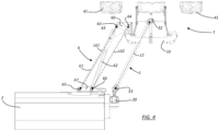
- the arrow (V), visible in Fig.1 indicates the direction of travel of the tractor (T), which moves forward with the front part, which, provided with the front wheels (41), precedes the rear part, which in turn is provided with the rear wheels identified by the reference (42).
- the agricultural machine (1) is connected to the tractor (T) by means of a connection structure (10), which is provided with three connection portions (11, 12, 13) for attachment to the three-point hitch (31, 32, 33) of the tractor (T).
- the proximal portion (60) of the articulating means (6), which allow the lateral displacement (X) of the operating head (2) of the machine (1), is fixed to the connecting structure (10).
- the articulating means (6) comprise an articulated parallelogram composed of two arms (61) and (62) which are hinged at their proximal ends to a bracket (60) fixed to the connecting structure (10) and at their distal ends to a plate (67) fixed to the operating head (2) of the machine (1).
- a bracket (60) fixed to the connecting structure (10)
- a plate (67) fixed to the operating head (2) of the machine (1).
- the bracket (60) there are two hinge points or pins (63, 64) around which the arm (61) and the arm (62) are hinged, respectively.
- the plate (67) there are two hinge points or hinge pins (65) and (66) around which the arm (61) and the arm (62) are hinged, respectively.
- the kinematic connection between the tractor's (T) power take-off (30) and the coupling (20) located on the operating head (2) is defined by a cardan shaft (5).
- the cardan shaft (5) has a proximal end (52) connected to the power take-off (30) of the tractor (T) and a distal end (53) connected to the coupling (20) located on the operating head (2).
- the cardan shaft (5) is made up of two telescopic elements (50) and (51), of which the external coaxial element (50) is in a proximal position, i.e. connected to the power take-off (30) via the proximal end (52).
- there is only one transmission means connecting the transmission between the tractor (T) and the operating head (2) in the example consisting of a mulcher (2).
- the means of articulation (6) between the tractor and the machine are supported by the connecting structure (10) at a point which is never external to the connecting portions of the same structure intended for the three-point hitch of the tractor; in particular, the hinge points (63) and (64) are never external to the points (31) and (32) of the lifting arms, i.e. the hinge points (63) and (64) are no further from the tractor than the said points (31) and (32) of the lifting arms.
- a first point is understood to be more internal than a second point when the first point is closer to the tractor, i.e. back disposed in the direction of travel (V) of the tractor (T).
- the plate (60) on which the arms (61) and (62) are hinged does not face outwards (i.e. beyond the pins of the tractor's linkage) as in conventional machines of the known type, but is on the same axis or, rather, further internal from the linkage.
- the value of the distance (K) between a theoretical axis (W) passing from the point of hinge of the articulation means (6) and a theoretical axis (Y) passing between the connection portions between the connection structure (10) and the arms of the three-point hitch is always greater than or equal to zero.
- This particular configuration of the machine (1) which essentially brings the hinge of the parallelogram arms behind that of the lift arms, allows the cardan shaft to be used at 1000 rpm with an extremely limited offset between its telescopic components (50, 51).
- the displacement of the proximal hinge point of the articulated parallelogram (5) to a position internal in respect to the lift arms results in an extremely favourable geometry of the machine that allows the cardan shaft to be used in all operating ranges/angles, which would be impossible with known agricultural machines in which this hinge point is outside the connecting structure (10).
- a fundamental aspect of the present invention relates to the fact that the length of the cardan shaft (5) is substantially equal to the length of the segments geometrically joining the hinge points (63, 65; 64, 66) of the articulating means (6).
- the value (L5) of the length of the cardan shaft (5) corresponds to the value of the lengths (L61, L62) of the movable sides of the articulated parallelogram defining the articulating means (6).
- Fig. 1-5 the value (L5) of the length of the cardan shaft (5) corresponds to the value of the lengths (L61, L62) of the movable sides of the articulated parallelogram defining the articulating means (6).
- the reference (L61) indicates the length of the arm (61) that is hinged at the hinge points (63) and (65), while the reference (L62) indicates the length of the segment that geometrically joins the hinge points (64) and (66), around which the arm (62) is hinged, which has its proximal end curved so as not to interfere with the structure (10) during rotation around the pivot or hinge point (64).
- the cardan shaft (5) has its minimum length, which can be seen in the configuration of Fig.1 in which its inner telescopic element (51) is substantially completely covered by the outer telescopic element (50), which corresponds to the lengths (L61) and (L62) of the arms (61) and (62) of the articulated parallelogram (6), considering as the length of the arm (62) the value (L62) corresponding to its generatrix, i.e., to the segment joining the two pins (64, 66) around which it is hinged.
- the same cardan shaft (5) presents a considerably smaller extension compared to the extension reached in similar configurations by cardan shafts that equip traditional type equipment.
- the maximum extension reached by a cardan shaft made in accordance with the present invention is contained in 10% of the length of the same cardan shaft.
- maximum offsets contained between 10cm and 15cm for cardan shafts of 210cm i.e. offsets contained between 4.7% and 7.1%.
- the invention relates to an agricultural machine (1) of the usable type carried by a tractor (T) from which it receives motion by means of a cardan shaft (5) kinematically connecting a power take-off (30) of the tractor (T) with a corresponding coupling (20) provided on a head (2) of the machine (1), said agricultural machine (1) being provided with a connection structure (10) provided with means or elements of connection (11, 12, 13) to a three-point hitch (31, 32, 33) comprising two connections (11, 12) for the lift arms (31, 32) presented by the tractor (T); between said connecting structure (10) and said head (2) being arranged and acting means of articulation (6) which are hinged in at least one hinge point (63, 64) to the structure (10) and in at least one hinge point (65, 66) to the head (2).
- the agricultural machine (1) is characterized in that the hinge point (63, 64) of the articulation means (6) to the connecting structure (10) is arranged aligned with or internal with respect to the connections (11, 12) for the lift arms (31, 32), i.e. the hinge point (63, 64) is arranged aligned with or internal with respect to said connections (11, 12) when the machine (1) is supported at the front by the tractor (T).
- the hinge point (63, 64) of said articulation means (6) to the linkage structure (10) is disposed internal to the connections (11, 12) for the lift arms (31, 32).
- the articulation means (6) may comprise an articulated parallelogram comprising two arms (61) and (62) which are hinged at their proximal ends to a bracket (60) attached to the connecting structure (10) and at their distal ends to a plate (67) attached to the operating head (2) of the machine (1).
- a bracket (60) there are two hinge points or pins (63) and (64) around which the arm (61) and the arm (62) are hinged, respectively;
- a plate (67) there are two hinge points or pins (65) and (66) around which the arm (61) and the arm (62) are hinged, respectively.
- the cardan shaft (5) is unique and is composed of two coaxial tubular elements (50, 51) fitted one on the other.
- the machine (1) is an operating machine intended for one of the following uses: agriculture, forestry, road maintenance, riverbed maintenance.
- the agricultural machine is an operating machine among those included in the set consisting of: brush cutter, mulcher, ditch digger, forestry equipment, soil working equipment.
- the value (L5) of the minimum length of said cardan shaft (5) is substantially equal to the value (L61, L62) of the length of the segments geometrically joining the hinge points (63, 64) of the articulation means (6) associated with said structure (10) with the corresponding hinge points (65, 66) of the articulation means (6) associated with said head (2).
- the maximum extraction between said tubular elements (50, 51) forming said cardan shaft (5) is less than 10%.
- the articulation means (6) comprise two arms (61) and (62) which are hinged in their proximal ends to a bracket (60) fixed to the connection structure (10) and in their distal ends to a plate (67) fixed to the operating head (2) of the machine (1).
- the bracket (60) there are provided two hinge points or pins (63) and (64) around which the arm (61) and the arm (62) are hinged, respectively.
- two hinge points or pins (65) and (66) are provided on the plate (67) around which the arm (61) and the arm (62) are hinged, respectively.
- the kinematic connection between the power take-off (30) of the tractor (T) and the coupling (20) located on the operating head (2) is defined by a cardan shaft (5) in a single body.
- the cardan shaft (5) is provided with a proximal end (52) connected to the power take-off (30) of the tractor (T) and a distal end (53) connected to the coupling (20) located on the operating head (2).
- a single transmission means connecting the transmission between the tractor (T) and the operating head (2), in the example consisting of a mulcher (2).
- the means of articulation (6) between the tractor and the machine are supported by the connecting structure (10) at a point which is never external to the connecting portions of the same structure intended for the three-point hitch of the tractor, in particular, the hinge points (63) and (64) are never external to the points (31) and (32) of the lifting arms, i.e., the hinge points (63) and (64) are no further from the tractor than said points (31) and (32) of the lifting arms.
- the term external means further away from the tractor.
- a first point is considered to be further internal than a second point when the first point is closer to the tractor, i.e. further back in the forward direction (V) of the tractor (T).
- the direction of travel (V) of the tractor (T) corresponds to a first direction (V) indicated as longitudinal, while the direction (X) orthogonal thereto is indicated as transverse direction (X).
- one of the hinge points of the articulation means (6), defined by the pin (64), in addition to being internal to the structure (10) in the longitudinal direction, is also internal to the same structure (1) in the transverse direction.
- the hinge point of the arm (62), which is defined by the pin (64) is placed further back (see K value) with respect to the structure (10) and is placed inside the same structure in the transverse direction (X).
- the pin (64) is therefore between the structure (10) and the tractor (T) in the longitudinal direction (V) and is inside the span (X10) defined by the projection in the transverse direction from the same structure (10).
- the hinge point makes it possible to achieve angles that have been found to be surprising when compared to a known machine in which the hinge points of the means of articulation are external to the same support structure in the longitudinal and transverse directions.
- the value of the angle indicated with ( ⁇ ) in Fig.8 is substantially equal to 30°. In this way, the operating head (2) can be kept in front of the tractor (T) in the centre of its path, i.e. in an area in which its control is safe.
- the plate (60) on which the arms (61) and (62) are hinged does not face outwards (i.e. beyond the pins of the tractor's lift attachment) as in traditional machines of the known type, but is on the same axis or, better still, more internal with respect to the lift attachment.
- the same plate (60) has at least one internal portion according to the transverse direction (X) so as to arrange also in the transverse direction (X) the pin (64) within the area (X10) defined by the structure (10).
- the value of the distance (K) between a theoretical axis (W) passing through the hinge point of the means of articulation (6) and a theoretical axis (Y) passing between the portions of connection between the connecting structure (10) and the arms of the three-point hitch is always greater than or equal to zero, contributing to the achievement of the advantages previously described.
- the arrangement of the hinge point (64) within the structure (10) in the transverse direction (X) further contributes to increasing the possibility of machine articulation, even in the case of a single-body cardan shaft (5).
- the agricultural machine (1) is moved along a longitudinal direction (V) and the means of articulation (6) comprise an arm (62) whose hinge point (64) to the connecting structure (10) is arranged inside the space (X10) defined by said structure (10) in a direction (X) transverse to said longitudinal direction.
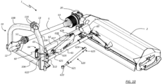
- a bracket (629) is placed on the arm (62) for receiving a corresponding pin (630) intended for fixing the distal end (623) of a jack (620).
- the bracket (629) is formed of two parallel portions drilled to receive the pin (630).
- the stem (621) supports the proximal end (622) of the jack, the proximal end being collar-like in shape and hinged on a pin (63) to which the other arm (61) is hinged.
- the pin (64) is received by the coaxial holes (60B) provided on the plate (60) supported by the structure (10). On the same plate (60) there are two more coaxial holes (60A) intended to accommodate the pin (63) that fixes the arm (61).
- the arm (61) defines a strut; in particular, in the illustrated example the arm (61) is formed by a gas accumulator/shock absorber capable of constituting a compression constraint (i.e. a strut) provided with a safety limit; under normal conditions the arm (61) is rigid and fixed, but when the operating head (2) encounters an obstacle that prevents the advancement, the gas accumulator/shock absorber it unlocks, shortening its extension in length and thus preventing any damage.
- the arm (61) is provided with a cylindrical collar (612) fitted on the pin (63) and a cylindrical collar (613) fitted on the pin (65).
- reference (8) indicates a nut
- reference (80) indicates a bushing
- reference (81) indicates a washer, a flat washer or other spacer. The function of these components is not described since they are of known type.
- the arm (62) is provided with stroke adjustment means, designed to allow the variation of the end strokes according to the use of the machine (1) and the conformation of the support structure (10) and the three-point hitch (31, 32, 33) presented by the tractor (T).
- stroke adjustment means designed to allow the variation of the end strokes according to the use of the machine (1) and the conformation of the support structure (10) and the three-point hitch (31, 32, 33) presented by the tractor (T).
- the adjustment of the end strokes, as described below, is extremely simple and does not require any special skills or instrumentation.
- the end-of-stroke adjustment means of the jack (620) includes an end-of-stroke adjuster (627) defined by a box body that can be fitted on the jack (620).
- the end-of-stroke adjuster (627) is provided at its distal end with a first plurality of holes (625) through which passes the pin (630) that secures the distal end (623) of the jack (620).
- a second plurality of holes (624) also passable through by the pin (630).
- a ring or eyebolt (82) can be provided on the distal end (623).
- holes (625) and (624) it is possible to fix, by positioning the pin (630) in the said first (625) and second plurality of holes (624), two different end-strokes for respective configurations of minimum and maximum extension of the jack (620), corresponding to different positions of the machine (1).
- this end-stroke is determined by the contact of the proximal portion (626) of the body of the end-stroke adjuster (627) with the hollow cylindrical body or collar (622) which fixes the jack (620) to the pin (63).
- the variation in the hole (625) used to pass the pin (630) results in a corresponding variation in the retraction of the jack (620).
- the portion (626) of the adjuster (627) will impact the collar (622) sooner than when the same pin (63) is inserted into a more internally placed hole (more proximal position).
- the jack (620) is to be retracted by a maximum value (i.e., if it is to "shorten” as much as possible) the pin (630) must pass through the more internally placed hole (625).
- the adjuster (627) is fitted on the jack (620) and is covered by a cover element (628) which in Figs. 10-11 is marked with the inscription "ORSI Group" which is not a limitation.
- connection structure (10) consists of a base portion (10A) placed below and two upper arched portions (10B) that join at the top in correspondence with the connection element (13) for the three-point attachment placed above.
- the upper connection element (13) is outwardly displaced with respect to said longitudinal direction (V), i.e. it is outwardly located with respect to the pin or hinge point (64).
- connection elements (11, 12, 13) comprise three pairs of plates provided with corresponding plurality of holes (110, 120, 130) so as to allow the fixing of the structure itself (10) to three-point connections of different sizes.
- the compatibility of the machine of the invention is really wide and allows the association with tractors provided with different types of three-point couplings.
- a pin with a handle (111), possibly provided with a snap pin, and a pin with a handle (113) have been represented for illustrative purposes. Obviously, the fastening means may be different.
Landscapes
- Life Sciences & Earth Sciences (AREA)
- Environmental Sciences (AREA)
- Engineering & Computer Science (AREA)
- Mechanical Engineering (AREA)
- Soil Sciences (AREA)
- Zoology (AREA)
- Agricultural Machines (AREA)
Applications Claiming Priority (1)
| Application Number | Priority Date | Filing Date | Title |
|---|---|---|---|
| IT102019000025861A IT201900025861A1 (it) | 2019-12-31 | 2019-12-31 | Macchina agricola |
Publications (2)
| Publication Number | Publication Date |
|---|---|
| EP3845048A1 EP3845048A1 (en) | 2021-07-07 |
| EP3845048B1 true EP3845048B1 (en) | 2025-01-15 |
Family
ID=70228653
Family Applications (1)
| Application Number | Title | Priority Date | Filing Date |
|---|---|---|---|
| EP20020657.1A Active EP3845048B1 (en) | 2019-12-31 | 2020-12-30 | Agricultural machine |
Country Status (4)
| Country | Link |
|---|---|
| EP (1) | EP3845048B1 (pl) |
| ES (1) | ES3014991T3 (pl) |
| IT (1) | IT201900025861A1 (pl) |
| PL (1) | PL3845048T3 (pl) |
Families Citing this family (1)
| Publication number | Priority date | Publication date | Assignee | Title |
|---|---|---|---|---|
| DE102023110900A1 (de) | 2023-04-27 | 2024-10-31 | Pöttinger Landtechnik Gmbh | Frontanbaubare Erntemaschine |
Family Cites Families (8)
| Publication number | Priority date | Publication date | Assignee | Title |
|---|---|---|---|---|
| US3930543A (en) * | 1974-03-22 | 1976-01-06 | Maurer Richard G | Tractor attachment |
| ITVI20050038A1 (it) * | 2005-02-10 | 2006-08-11 | Berti Macchine Agricole Srl | Trinciatrice per erbe, arbusti, sarmenti e simili |
| JP2012039941A (ja) * | 2010-08-19 | 2012-03-01 | Matsuyama Plow Mfg Co Ltd | 草刈機 |
| JP5700510B2 (ja) * | 2010-09-15 | 2015-04-15 | 松山株式会社 | 草刈機 |
| IT1402605B1 (it) * | 2010-11-09 | 2013-09-13 | Tierre Srl | Macchina trinciatrice per manutenzione di bordi stradali |
| ES2618331B2 (es) * | 2015-12-18 | 2017-12-21 | Javier Cancela Rodriguez | Mecanismo de alineado de transmisiones cardán en máquinas conectadas a tractor de desplazamiento lateral de brazos paralelos |
| IT201600112532A1 (it) | 2016-11-08 | 2018-05-08 | Orsi Group S R L | apparecchiatura per macchine agricole e similari |
| IT201600113433A1 (it) * | 2016-11-10 | 2018-05-10 | Claudio Corsetti | Sistema di movimentazione per un qualsiasi macchinario agricolo. |
-
2019
- 2019-12-31 IT IT102019000025861A patent/IT201900025861A1/it unknown
-
2020
- 2020-12-30 EP EP20020657.1A patent/EP3845048B1/en active Active
- 2020-12-30 PL PL20020657.1T patent/PL3845048T3/pl unknown
- 2020-12-30 ES ES20020657T patent/ES3014991T3/es active Active
Also Published As
| Publication number | Publication date |
|---|---|
| PL3845048T3 (pl) | 2025-04-28 |
| EP3845048A1 (en) | 2021-07-07 |
| ES3014991T3 (en) | 2025-04-28 |
| IT201900025861A1 (it) | 2021-07-01 |
Similar Documents
| Publication | Publication Date | Title |
|---|---|---|
| JP3781133B2 (ja) | 改良された保護装置を有する植物刈取り用農業機械 | |
| RU2462859C2 (ru) | Жатка комбайна или уборочной машины | |
| SU1019987A3 (ru) | Сельскохоз йственное орудие | |
| JP2847116B2 (ja) | 作業の進行方向を横切る方向に延びた作業具群を備えた草刈機 | |
| RU2615483C2 (ru) | Усовершенствованное соединительное устройство и сельскохозяйственная машина, содержащая такое устройство | |
| JPH03183413A (ja) | 改良された重量軽減装置を備えた草刈機 | |
| JP5980235B2 (ja) | 干草作り機 | |
| EP3845048A1 (en) | Agricultural machine | |
| RU2719182C1 (ru) | Виндроуэр со множеством жаток | |
| EP1529430B1 (en) | Device at a soil tillage implement | |
| KR102634561B1 (ko) | 자동 확장형 농업용 작업기 | |
| JP3766712B2 (ja) | 集草機におけるレーキロータの支持フレーム | |
| DK1488685T4 (da) | Høbjergningsmaskine | |
| EP0642731A1 (en) | A mowing machine | |
| EP3918909B1 (en) | Stump cutter drive system | |
| JP3817624B2 (ja) | 切断機械 | |
| KR20120024114A (ko) | 트랙터 장착용 제초장치 | |
| JP6076674B2 (ja) | 代かき作業機 | |
| JP7144847B2 (ja) | 農作業機 | |
| US4171021A (en) | Soil cultivating implements | |
| JP2005052121A (ja) | 農作業機 | |
| AU2020201787B2 (en) | Agricultural machine and folding method for an agricultural machine | |
| JP6905749B2 (ja) | 農作業機 | |
| EP0479747A1 (en) | An implement attachment means for mechanical diggers | |
| JP7634268B2 (ja) | オフセット作業機 |
Legal Events
| Date | Code | Title | Description |
|---|---|---|---|
| PUAI | Public reference made under article 153(3) epc to a published international application that has entered the european phase |
Free format text: ORIGINAL CODE: 0009012 |
|
| STAA | Information on the status of an ep patent application or granted ep patent |
Free format text: STATUS: THE APPLICATION HAS BEEN PUBLISHED |
|
| AK | Designated contracting states |
Kind code of ref document: A1 Designated state(s): AL AT BE BG CH CY CZ DE DK EE ES FI FR GB GR HR HU IE IS IT LI LT LU LV MC MK MT NL NO PL PT RO RS SE SI SK SM TR |
|
| STAA | Information on the status of an ep patent application or granted ep patent |
Free format text: STATUS: REQUEST FOR EXAMINATION WAS MADE |
|
| 17P | Request for examination filed |
Effective date: 20220112 |
|
| RBV | Designated contracting states (corrected) |
Designated state(s): AL AT BE BG CH CY CZ DE DK EE ES FI FR GB GR HR HU IE IS IT LI LT LU LV MC MK MT NL NO PL PT RO RS SE SI SK SM TR |
|
| P01 | Opt-out of the competence of the unified patent court (upc) registered |
Effective date: 20230630 |
|
| STAA | Information on the status of an ep patent application or granted ep patent |
Free format text: STATUS: EXAMINATION IS IN PROGRESS |
|
| 17Q | First examination report despatched |
Effective date: 20231006 |
|
| GRAP | Despatch of communication of intention to grant a patent |
Free format text: ORIGINAL CODE: EPIDOSNIGR1 |
|
| STAA | Information on the status of an ep patent application or granted ep patent |
Free format text: STATUS: GRANT OF PATENT IS INTENDED |
|
| INTG | Intention to grant announced |
Effective date: 20240916 |
|
| GRAS | Grant fee paid |
Free format text: ORIGINAL CODE: EPIDOSNIGR3 |
|
| GRAA | (expected) grant |
Free format text: ORIGINAL CODE: 0009210 |
|
| STAA | Information on the status of an ep patent application or granted ep patent |
Free format text: STATUS: THE PATENT HAS BEEN GRANTED |
|
| AK | Designated contracting states |
Kind code of ref document: B1 Designated state(s): AL AT BE BG CH CY CZ DE DK EE ES FI FR GB GR HR HU IE IS IT LI LT LU LV MC MK MT NL NO PL PT RO RS SE SI SK SM TR |
|
| REG | Reference to a national code |
Ref country code: CH Ref legal event code: EP Ref country code: GB Ref legal event code: FG4D |
|
| REG | Reference to a national code |
Ref country code: DE Ref legal event code: R096 Ref document number: 602020044695 Country of ref document: DE |
|
| REG | Reference to a national code |
Ref country code: IE Ref legal event code: FG4D |
|
| REG | Reference to a national code |
Ref country code: NL Ref legal event code: MP Effective date: 20250115 |
|
| PG25 | Lapsed in a contracting state [announced via postgrant information from national office to epo] |
Ref country code: NL Free format text: LAPSE BECAUSE OF FAILURE TO SUBMIT A TRANSLATION OF THE DESCRIPTION OR TO PAY THE FEE WITHIN THE PRESCRIBED TIME-LIMIT Effective date: 20250115 |
|
| PG25 | Lapsed in a contracting state [announced via postgrant information from national office to epo] |
Ref country code: RS Free format text: LAPSE BECAUSE OF FAILURE TO SUBMIT A TRANSLATION OF THE DESCRIPTION OR TO PAY THE FEE WITHIN THE PRESCRIBED TIME-LIMIT Effective date: 20250415 |
|
| PG25 | Lapsed in a contracting state [announced via postgrant information from national office to epo] |
Ref country code: FI Free format text: LAPSE BECAUSE OF FAILURE TO SUBMIT A TRANSLATION OF THE DESCRIPTION OR TO PAY THE FEE WITHIN THE PRESCRIBED TIME-LIMIT Effective date: 20250115 |
|
| REG | Reference to a national code |
Ref country code: LT Ref legal event code: MG9D |
|
| PG25 | Lapsed in a contracting state [announced via postgrant information from national office to epo] |
Ref country code: IS Free format text: LAPSE BECAUSE OF FAILURE TO SUBMIT A TRANSLATION OF THE DESCRIPTION OR TO PAY THE FEE WITHIN THE PRESCRIBED TIME-LIMIT Effective date: 20250515 Ref country code: NO Free format text: LAPSE BECAUSE OF FAILURE TO SUBMIT A TRANSLATION OF THE DESCRIPTION OR TO PAY THE FEE WITHIN THE PRESCRIBED TIME-LIMIT Effective date: 20250415 |
|
| REG | Reference to a national code |
Ref country code: AT Ref legal event code: MK05 Ref document number: 1759179 Country of ref document: AT Kind code of ref document: T Effective date: 20250115 |
|
| PG25 | Lapsed in a contracting state [announced via postgrant information from national office to epo] |
Ref country code: HR Free format text: LAPSE BECAUSE OF FAILURE TO SUBMIT A TRANSLATION OF THE DESCRIPTION OR TO PAY THE FEE WITHIN THE PRESCRIBED TIME-LIMIT Effective date: 20250115 |
|
| PG25 | Lapsed in a contracting state [announced via postgrant information from national office to epo] |
Ref country code: LV Free format text: LAPSE BECAUSE OF FAILURE TO SUBMIT A TRANSLATION OF THE DESCRIPTION OR TO PAY THE FEE WITHIN THE PRESCRIBED TIME-LIMIT Effective date: 20250115 Ref country code: PT Free format text: LAPSE BECAUSE OF FAILURE TO SUBMIT A TRANSLATION OF THE DESCRIPTION OR TO PAY THE FEE WITHIN THE PRESCRIBED TIME-LIMIT Effective date: 20250515 |
|
| PG25 | Lapsed in a contracting state [announced via postgrant information from national office to epo] |
Ref country code: BG Free format text: LAPSE BECAUSE OF FAILURE TO SUBMIT A TRANSLATION OF THE DESCRIPTION OR TO PAY THE FEE WITHIN THE PRESCRIBED TIME-LIMIT Effective date: 20250115 Ref country code: GR Free format text: LAPSE BECAUSE OF FAILURE TO SUBMIT A TRANSLATION OF THE DESCRIPTION OR TO PAY THE FEE WITHIN THE PRESCRIBED TIME-LIMIT Effective date: 20250416 |
|
| PG25 | Lapsed in a contracting state [announced via postgrant information from national office to epo] |
Ref country code: AT Free format text: LAPSE BECAUSE OF FAILURE TO SUBMIT A TRANSLATION OF THE DESCRIPTION OR TO PAY THE FEE WITHIN THE PRESCRIBED TIME-LIMIT Effective date: 20250115 |
|
| PG25 | Lapsed in a contracting state [announced via postgrant information from national office to epo] |
Ref country code: SE Free format text: LAPSE BECAUSE OF FAILURE TO SUBMIT A TRANSLATION OF THE DESCRIPTION OR TO PAY THE FEE WITHIN THE PRESCRIBED TIME-LIMIT Effective date: 20250115 |
|
| PG25 | Lapsed in a contracting state [announced via postgrant information from national office to epo] |
Ref country code: SM Free format text: LAPSE BECAUSE OF FAILURE TO SUBMIT A TRANSLATION OF THE DESCRIPTION OR TO PAY THE FEE WITHIN THE PRESCRIBED TIME-LIMIT Effective date: 20250115 |
|
| PG25 | Lapsed in a contracting state [announced via postgrant information from national office to epo] |
Ref country code: DK Free format text: LAPSE BECAUSE OF FAILURE TO SUBMIT A TRANSLATION OF THE DESCRIPTION OR TO PAY THE FEE WITHIN THE PRESCRIBED TIME-LIMIT Effective date: 20250115 |
|
| REG | Reference to a national code |
Ref country code: DE Ref legal event code: R097 Ref document number: 602020044695 Country of ref document: DE |
|
| PG25 | Lapsed in a contracting state [announced via postgrant information from national office to epo] |
Ref country code: CZ Free format text: LAPSE BECAUSE OF FAILURE TO SUBMIT A TRANSLATION OF THE DESCRIPTION OR TO PAY THE FEE WITHIN THE PRESCRIBED TIME-LIMIT Effective date: 20250115 Ref country code: EE Free format text: LAPSE BECAUSE OF FAILURE TO SUBMIT A TRANSLATION OF THE DESCRIPTION OR TO PAY THE FEE WITHIN THE PRESCRIBED TIME-LIMIT Effective date: 20250115 |
|
| PG25 | Lapsed in a contracting state [announced via postgrant information from national office to epo] |
Ref country code: RO Free format text: LAPSE BECAUSE OF FAILURE TO SUBMIT A TRANSLATION OF THE DESCRIPTION OR TO PAY THE FEE WITHIN THE PRESCRIBED TIME-LIMIT Effective date: 20250115 |
|
| PG25 | Lapsed in a contracting state [announced via postgrant information from national office to epo] |
Ref country code: SK Free format text: LAPSE BECAUSE OF FAILURE TO SUBMIT A TRANSLATION OF THE DESCRIPTION OR TO PAY THE FEE WITHIN THE PRESCRIBED TIME-LIMIT Effective date: 20250115 |
|
| PLBE | No opposition filed within time limit |
Free format text: ORIGINAL CODE: 0009261 |
|
| STAA | Information on the status of an ep patent application or granted ep patent |
Free format text: STATUS: NO OPPOSITION FILED WITHIN TIME LIMIT |
|
| 26N | No opposition filed |
Effective date: 20251016 |
|
| PGFP | Annual fee paid to national office [announced via postgrant information from national office to epo] |
Ref country code: DE Payment date: 20251224 Year of fee payment: 6 |
|
| PGFP | Annual fee paid to national office [announced via postgrant information from national office to epo] |
Ref country code: IT Payment date: 20251223 Year of fee payment: 6 |
|
| PGFP | Annual fee paid to national office [announced via postgrant information from national office to epo] |
Ref country code: FR Payment date: 20251223 Year of fee payment: 6 |
|
| PGFP | Annual fee paid to national office [announced via postgrant information from national office to epo] |
Ref country code: PL Payment date: 20251229 Year of fee payment: 6 |
|
| PGFP | Annual fee paid to national office [announced via postgrant information from national office to epo] |
Ref country code: ES Payment date: 20260130 Year of fee payment: 6 |