EP3845103A1 - Dispositif melangeur - Google Patents
Dispositif melangeur Download PDFInfo
- Publication number
- EP3845103A1 EP3845103A1 EP20215660.0A EP20215660A EP3845103A1 EP 3845103 A1 EP3845103 A1 EP 3845103A1 EP 20215660 A EP20215660 A EP 20215660A EP 3845103 A1 EP3845103 A1 EP 3845103A1
- Authority
- EP
- European Patent Office
- Prior art keywords
- arm
- rotation
- whip
- axis
- bowl
- Prior art date
- Legal status (The legal status is an assumption and is not a legal conclusion. Google has not performed a legal analysis and makes no representation as to the accuracy of the status listed.)
- Granted
Links
Images

Classifications
-
- A—HUMAN NECESSITIES
- A47—FURNITURE; DOMESTIC ARTICLES OR APPLIANCES; COFFEE MILLS; SPICE MILLS; SUCTION CLEANERS IN GENERAL
- A47J—KITCHEN EQUIPMENT; COFFEE MILLS; SPICE MILLS; APPARATUS FOR MAKING BEVERAGES
- A47J43/00—Implements for preparing or holding food, not provided for in other groups of this subclass
- A47J43/04—Machines for domestic use not covered elsewhere, e.g. for grinding, mixing, stirring, kneading, emulsifying, whipping or beating foodstuffs, e.g. power-driven
- A47J43/07—Parts or details, e.g. mixing tools, whipping tools
- A47J43/0705—Parts or details, e.g. mixing tools, whipping tools for machines with tools driven from the upper side
- A47J43/0711—Parts or details, e.g. mixing tools, whipping tools for machines with tools driven from the upper side mixing, whipping or cutting tools
-
- A—HUMAN NECESSITIES
- A47—FURNITURE; DOMESTIC ARTICLES OR APPLIANCES; COFFEE MILLS; SPICE MILLS; SUCTION CLEANERS IN GENERAL
- A47J—KITCHEN EQUIPMENT; COFFEE MILLS; SPICE MILLS; APPARATUS FOR MAKING BEVERAGES
- A47J43/00—Implements for preparing or holding food, not provided for in other groups of this subclass
- A47J43/04—Machines for domestic use not covered elsewhere, e.g. for grinding, mixing, stirring, kneading, emulsifying, whipping or beating foodstuffs, e.g. power-driven
- A47J43/046—Machines for domestic use not covered elsewhere, e.g. for grinding, mixing, stirring, kneading, emulsifying, whipping or beating foodstuffs, e.g. power-driven with tools driven from the bottom side
-
- A—HUMAN NECESSITIES
- A21—BAKING; EDIBLE DOUGHS
- A21C—MACHINES OR EQUIPMENT FOR MAKING OR PROCESSING DOUGHS; HANDLING BAKED ARTICLES MADE FROM DOUGH
- A21C1/00—Mixing or kneading machines for the preparation of dough
- A21C1/02—Mixing or kneading machines for the preparation of dough with vertically-mounted tools; Machines for whipping or beating
-
- A—HUMAN NECESSITIES
- A47—FURNITURE; DOMESTIC ARTICLES OR APPLIANCES; COFFEE MILLS; SPICE MILLS; SUCTION CLEANERS IN GENERAL
- A47J—KITCHEN EQUIPMENT; COFFEE MILLS; SPICE MILLS; APPARATUS FOR MAKING BEVERAGES
- A47J43/00—Implements for preparing or holding food, not provided for in other groups of this subclass
- A47J43/04—Machines for domestic use not covered elsewhere, e.g. for grinding, mixing, stirring, kneading, emulsifying, whipping or beating foodstuffs, e.g. power-driven
- A47J43/07—Parts or details, e.g. mixing tools, whipping tools
- A47J43/08—Driving mechanisms
- A47J43/082—Driving mechanisms for machines with tools driven from the upper side
-
- A—HUMAN NECESSITIES
- A47—FURNITURE; DOMESTIC ARTICLES OR APPLIANCES; COFFEE MILLS; SPICE MILLS; SUCTION CLEANERS IN GENERAL
- A47J—KITCHEN EQUIPMENT; COFFEE MILLS; SPICE MILLS; APPARATUS FOR MAKING BEVERAGES
- A47J43/00—Implements for preparing or holding food, not provided for in other groups of this subclass
- A47J43/10—Egg-whisks; Cream-beaters, i.e. hand implements or hand-driven devices
- A47J43/1006—Hand-driven mixing devices with rotating tools, e.g. sticking out from the bottom of the mixing receptacle; with rotating bowls; with an additional function
- A47J43/1018—Hand-driven mixing devices with rotating tools, e.g. sticking out from the bottom of the mixing receptacle; with rotating bowls; with an additional function the mixing device being fitted on the cover of, or directly on, the stationary mixing receptacle
-
- B—PERFORMING OPERATIONS; TRANSPORTING
- B01—PHYSICAL OR CHEMICAL PROCESSES OR APPARATUS IN GENERAL
- B01F—MIXING, e.g. DISSOLVING, EMULSIFYING OR DISPERSING
- B01F27/00—Mixers with rotary stirring devices in fixed receptacles; Kneaders
- B01F27/05—Stirrers
- B01F27/07—Stirrers characterised by their mounting on the shaft
- B01F27/072—Stirrers characterised by their mounting on the shaft characterised by the disposition of the stirrers with respect to the rotating axis
- B01F27/0721—Stirrers characterised by their mounting on the shaft characterised by the disposition of the stirrers with respect to the rotating axis parallel with respect to the rotating axis
-
- B—PERFORMING OPERATIONS; TRANSPORTING
- B01—PHYSICAL OR CHEMICAL PROCESSES OR APPARATUS IN GENERAL
- B01F—MIXING, e.g. DISSOLVING, EMULSIFYING OR DISPERSING
- B01F27/00—Mixers with rotary stirring devices in fixed receptacles; Kneaders
- B01F27/05—Stirrers
- B01F27/11—Stirrers characterised by the configuration of the stirrers
- B01F27/112—Stirrers characterised by the configuration of the stirrers with arms, paddles, vanes or blades
- B01F27/1121—Stirrers characterised by the configuration of the stirrers with arms, paddles, vanes or blades pin-shaped
-
- B—PERFORMING OPERATIONS; TRANSPORTING
- B01—PHYSICAL OR CHEMICAL PROCESSES OR APPARATUS IN GENERAL
- B01F—MIXING, e.g. DISSOLVING, EMULSIFYING OR DISPERSING
- B01F27/00—Mixers with rotary stirring devices in fixed receptacles; Kneaders
- B01F27/55—Mixers with rotary stirring devices in fixed receptacles; Kneaders with stirrers driven by the moving material
-
- B—PERFORMING OPERATIONS; TRANSPORTING
- B01—PHYSICAL OR CHEMICAL PROCESSES OR APPARATUS IN GENERAL
- B01F—MIXING, e.g. DISSOLVING, EMULSIFYING OR DISPERSING
- B01F27/00—Mixers with rotary stirring devices in fixed receptacles; Kneaders
- B01F27/80—Mixers with rotary stirring devices in fixed receptacles; Kneaders with stirrers rotating about a substantially vertical axis
- B01F27/95—Mixers with rotary stirring devices in fixed receptacles; Kneaders with stirrers rotating about a substantially vertical axis with stirrers having planetary motion, i.e. rotating about their own axis and about a sun axis
Definitions
- the present invention relates to articles for culinary preparation and relates more particularly to a device for producing mixtures, in particular for allowing the stirring and emulsion of the ingredients making up the culinary preparation, said ingredients being poured into the device.
- whisk it is understood in the present document, a utensil comprising a plurality of strands making it possible to mix, beat and emulsify together food ingredients.
- the manual whisk makes it possible to make a vinaigrette (i.e. an emulsion of oil and vinegar) without hindrance, the operation becomes much more laborious and tiring if you wish to prepare, for example, mayonnaise or snow whites.
- a vinaigrette i.e. an emulsion of oil and vinegar
- An emulsion is a suspension of an element in a phase in which it is not miscible. In most cases, these are two liquid media, droplets of one being dispersed in the other phase. The interface of the two media is generally stabilized by a compound which maintains the immiscible element in suspension.
- the most famous emulsion is mayonnaise.
- mayonnaise is an emulsion of oil (hydrophobic phase) in water, vinegar or lemon juice (aqueous phase), using egg yolk as surfactant.
- An emulsion can also be a suspension of a gas such as air in a liquid or semi-liquid.
- a gas such as air in a liquid or semi-liquid.
- foams where air in the form of bubbles is trapped in a liquid phase, for example egg whites whipped up to stiff peaks or whipped cream.
- egg white is an aqueous solution comprising in particular proteins.
- the whisk allows you to incorporate air bubbles into the egg white, which are trapped in the water and stabilized by the proteins.
- a whisk is rotated in a bowl.
- the rotation can be electric or manual.
- the whip is connected to a gear train making it possible to increase the speed of rotation of the whip.
- the gears are often found clogged and it is difficult to wash them properly.
- the raw egg is a vector of bacteria such as salmonella.
- gear trains involve complex systems, expensive to manufacture and therefore expensive to purchase for a user.
- a device for producing mixtures comprising an arm, adapted to be driven in rotation, about an axis of rotation of the arm, by drive means.
- the device comprises at least one whip mounted by a pivot connection to the arm in free rotation, about an axis of rotation of the whip separate from the axis of rotation of the arm.
- the whip has a radial extension having a dimension greater than a distance between the axis of rotation of the arm and the axis of rotation of the whip
- the arm has a C-shape with a first radial portion having the pivot connection to the whip, a substantially axial portion and a second radial portion.
- the substantially axial portion of the arm may have at least one deflector adapted to direct a material towards the whip during the rotation of the arm and of the whip.
- the first radial portion of the arm may have a pin for connection to the drive means of the arm, the connection pin possibly being collinear with the axis of rotation of the arm.
- the whip may have a plurality of strands, each strand extending from the axis of rotation of the whip with a radial extension and at least one axial extension.
- the device can comprise a bowl adapted to receive the mixing arm and the whisk.
- the substantially axial portion of the arm can be adapted to brush against a side wall of a bowl.
- the bowl may have a side wall and a bottom wall, the bottom wall may have a rotational guide pin of the mixing arm, the guide pin may be collinear with the arm rotation axis.
- the second radial portion of the arm can be adapted to be linked in free rotation to the guide pin of the bottom wall of the bowl.
- the device may comprise a cover provided with a connection element cooperating with a connection element of the arm.
- the drive means may comprise means for rotating by human energy or by electrical energy.
- the manual drive means may comprise an automatically returning cable allowing the arm to be rotated.
- connection of the arm to the drive means may comprise a freewheel with ratchet.
- a device 1 is proposed for producing mixtures, and more particularly emulsions.
- the device 1 mainly comprises an arm 3 and a whip 5.
- the device 1 has a particularly clever kinematic structure, in which, on the one hand, the arm 3 is adapted to be driven in rotation, around an axis A of rotation of the arm 3, by training means; and on the other hand, the whip 5 is linked by a pivot connection to the arm 3 in free rotation, about an axis B of rotation of the whip 5 separate from the axis A of rotation of the arm.
- the difference in axes of rotation is a particularly advantageous technical arrangement which allows the whip 5 of the device 1 to reach a speed of rotation and a torque necessary for the production of an emulsion.
- the device 1 can very advantageously be used with manual or electric drive means.
- the device 1 can be provided as an accessory to a pre-existing assembly which may be a manual or electric assembly of the food processor type, or may be provided with a bowl and driving means to operate independently.
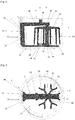
- the arm 3 has a C-shape with a first radial portion 31 having the pivot connection 40 to the whip 5, a substantially axial portion 33 and a second radial portion 34.
- the arm 3 can be made of plastic material. injected or molded.
- the material making up the arm 3 can have non-stick properties. These Non-stick properties can be obtained by a coating or by a compound embedded in the mass of the arm 3.
- the axial and radial directions are defined with respect to the axis A of rotation of the arm 3.
- the axial direction is a direction substantially parallel to the axis A of rotation of the arm 3.
- the radial direction is a direction. direction substantially perpendicular to the axis A of rotation of arm 3.
- the first radial portion 31 of the arm 3 is adapted to be connected to means for driving in rotation which comprise a female footprint complementary to the geometry of the pin 35.
- the first radial portion 31 of the arm 3 has a pin 35. connection to the drive means of the arm 3.
- the connection pin 35 is collinear with the axis A of rotation of the arm 3.
- the pin 35 is adapted to transmit a rotational movement.
- the pin 35 has a hexagonal section.
- the pin 35 could be a cylinder with a flat, or have, for example, a triangular or square section.
- the first radial portion 31 of the arm 3 has at its end a connecting hole 40 to the whip 5.
- the connecting hole 40 is adapted to receive one end of an axial shaft 51 of the whip 5 to allow the free rotation of the whip. whip 5 with respect to the arm 3.
- the connecting hole 40 is collinear with the axis of rotation B of the whip 5.
- the substantially axial portion 33 of the arm 3 has at least one deflector 36.
- the deflector 36 is suitable for orienting a material (for example a fluid or a food paste). towards whip 5 when rotating arm 3 and whip 5.
- deflector 36 is meant a portion which makes it possible to deflect the trajectory of a flow, and more particularly, a portion which makes it possible to direct a flow towards the whip 5.
- the substantially axial portion 33 of the arm 3 has two opposing deflectors 36. This arrangement allows advantageously to always be able to direct a fluid towards the whip regardless of the direction of rotation of the arm 3.
- each deflector 36 is an axial bevel.
- the substantially axial portion 33 of the arm 3 has two opposite axial fillets defining a median edge 37 separating the two fillets.
- the second radial portion 34 of the arm 3 has a first bore 38 adapted to receive a guide pin 72 of a bottom wall 73 of a bowl 7.
- the first bore 38 is collinear with the axis of rotation A of the arm 3
- This arrangement makes it possible to link the arm 3 in free rotation to the bowl 7.
- the objective of the connection between the second radial portion 34 of the arm 3 and the guide pin 72 of the bowl 7 is to guarantee the centering of the arm 3 during its rotation. Indeed, as will be detailed below, to produce an emulsion, the arm 3 can reach a high speed of rotation.
- the free rotation connection with the guide pin 72 makes it possible to keep the arm 3 in rotation around the axis A, avoiding possible effects of unbalance.
- the second radial portion 34 of the arm 3 has a second bore 39.
- the second bore 39 is adapted to accommodate one end of the axial shaft 51 of the whip 5.
- the second bore 39 is offset relative to the first bore 38.
- the second bore 39 is located on the axis of rotation B of the whip 5.
- the whip 5 is adapted to be linked in free rotation with the second bore 39. This connection mainly makes it possible to guarantee the centering of the whip during its rotation around the axis of rotation B. In other words, this connection makes it possible to avoid any swaying of the whip 5 during its rotation around the axis of rotation B.
- the arm 3 can be adapted to cooperate with the bowl 7.
- the arm 3 is dimensioned so that the substantially axial portion 33 of the arm 3 can brush against a side wall 74 of the bowl 7.
- the axis of rotation A of the arm corresponds to the axis of revolution of the bowl 7.
- a distance between the side wall 74 of the bowl 7 and the axis of rotation A corresponds to a radius of the bowl 7.
- a distance between the axis of rotation A (ie the pin 35) and the substantially axial portion 33 is necessary for a distance between the axis of rotation A (ie the pin 35) and the substantially axial portion 33 to be at least one millimeter less than the radius of the bowl 7.
- this arrangement allows the substantially axial portion 33 of the arm 3 to scrape material or fluid spilled on the wall of the bowl 7, to reorient it towards the whip 5 thanks to the deflector 36.
- the whip 5 has an axial shaft 51 of revolution adapted to be connected in rotation to the arm 3.
- the axial shaft 51 has a first end 52 adapted to be engaged in the connecting hole 40 of the first radial portion 31. of the arm 3.
- the axial shaft 51 has a second end 53 adapted to be engaged in the second bore 39 of the second radial portion 34 of the arm 3. It will be understood that in use, the axial shaft 51 is adapted to be collinear with the axis of rotation B of the whip 5.
- each strand 54 comprises a radial extension 55 and two axial extensions 56.
- the radial extension 55 is linked to a first end region of the axial shaft 51.
- This connection is preferably in a portion of the axial shaft 51. close to the first end 52 of the axial shaft 51.
- the radial extension 55 has a second end region split in two, to form a Y (ie a crow's foot ). From this region split in two leave the two axial extensions 56.
- This arrangement is particularly advantageous because it allows for each strand 54 to have two axial extensions 56.
- the number of axial extensions 56 of the whisk 5 influences the quality of the emulsion prepared.
- the length (ie the dimension between the two ends) of the radial extension 55 of each strand 54 is greater than a distance separating the pin 35 and the connecting hole 40.
- this arrangement allows the whip 5 to have a span (ie a diameter corresponding to the length of two opposite radial extensions) greater than the radius of the bowl 7.
- this arrangement allows the whip 5 to shake all the mixture in bowl 7, leaving no unmixed area.
- the whip can be a one-piece element made of plastic.
- a partially elastic material will be chosen.
- the axial extensions 55 of the strands 54 tend to move apart and oscillate.
- a user can separate the whip 5 from the arm 3 with a view to cleaning it thanks to the open C arrangement of the whip.
- the device 1 can comprise a bowl 7 adapted to receive the arm 3 and the whip 5.
- the bowl 7 has a shape in revolution such as a cylinder with a circular base.
- the bowl 7 can be made of plastic material.
- an optically transparent material can be chosen, so that a user can see the contents of the bowl through its walls.
- the bowl 7 can quite be made of glass, metal, wood or composite material.
- the bowl 7 may have a bottom wall 73 of circular shape, and a side wall 74 defining a cylindrical envelope.
- the bottom wall 73 has a guide pin 72 at its center.
- a free rim (i.e. which is not linked to the bottom wall) of the side wall 74 may have a groove or a flare adapted to receive a cover.
- the device 1 can further comprise a cover.
- the cover is suitable for being fixed to the bowl 7.
- the cover is provided with a connection element adapted to cooperate with a connection element of the arm 3.
- the cover may have a connection hole (female cavity) adapted to be traversed by the connection pin 35 of the arm 3.
- the cover may have a connection pin. and the arm 3 has a connection bore instead of the connection pin 35.
- the cover comprises means for driving the arm which comprise means for rotating by human energy or by electrical energy.
- the drive means comprise an automatic return cable allowing the arm to be rotated.
- This arrangement makes it possible to drive the arm 3 in rotation under the effect of traction on the cable.
- This is a particularly advantageous arrangement making it possible to obtain a high speed of rotation of the arm with a simple movement (a pull on the cable) of the user.
- connection of the arm to the drive means comprises a freewheel with ratchet.
- This arrangement allows the arm 3 and the whip 5 to always turn in the same direction.
- the system for rotating by traction on a cable operates (in summary) by winding a cable around an axis. Pulling the cable then rotates the axis in one direction. To rewind the cable, a return spring turns the shaft in the opposite direction.
- the ratchet freewheel system allows only the rotation initiated by the pulling of the cable to turn the arm 3. The system being in freewheel (disengaged) during the return of the cable.
- the arm 3 is in the bowl 7, linked in free pivot to the guide pin 72.
- the whip 5 is linked to the arm 3.
- a user introduces a mixture to be emulsified, for example egg white, into the bowl.
- the user pulls on the drive cable, then lets the cable rewind.
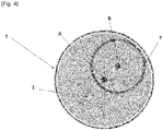
- the whip 5 has a combined rotational movement around the two axes A and B.
- the whip 5 turns on itself around the axis B while being driven by the arm 3 around the axis A. In a pictorial manner, this movement can be compared to that of the earth revolving on the one hand on itself and revolving around the sun.
- the whip 5 will cover an area corresponding to a projection of its wingspan on the trajectory of the axis B around the axis A. It is therefore understood that the specific dimensions of the radial extensions allow the whip to cover any the surface of the bottom wall of the bowl, leaving no empty space. This arrangement very advantageously makes it possible to guarantee a homogeneous emulsion.
Landscapes
- Engineering & Computer Science (AREA)
- Food Science & Technology (AREA)
- Mechanical Engineering (AREA)
- Chemical & Material Sciences (AREA)
- Chemical Kinetics & Catalysis (AREA)
- Life Sciences & Earth Sciences (AREA)
- Food-Manufacturing Devices (AREA)
- Mixers Of The Rotary Stirring Type (AREA)
- Accessories For Mixers (AREA)
- Processing And Handling Of Plastics And Other Materials For Molding In General (AREA)
Abstract
Description
- La présente invention concerne les articles de préparation culinaire et concerne plus particulièrement un dispositif pour réaliser des mélanges, notamment pour permettre le brassage et l'émulsion des ingrédients composant la préparation culinaire, lesdits ingrédients étant versés dans le dispositif.
- Dans le domaine de la préparation culinaire il est fréquent de devoir réaliser un mélange à partir d'ingrédient solide, liquide ou semi liquide dont la viscosité est plus ou moins visqueuse.
- Le moyen le plus simple connu pour réaliser un mélange est d'incorporer les ingrédients dans un bol et de les mélanger à l'aide d'une spatule ou d'un fouet manuel.
- Par fouet, il est entendu dans le présent document, un ustensile comprenant une pluralité de brins permettant de mélanger, battre, émulsionner ensemble des ingrédients alimentaires.
- Si le fouet manuel permet de réaliser sans encombre une vinaigrette (i.e. une émulsion d'huile et de vinaigre), l'opération devient beaucoup plus laborieuse et fatigante si l'on souhaite préparer, par exemple une mayonnaise ou des blancs en neige.
- Une émulsion est une suspension d'un élément dans une phase dans laquelle il n'est pas miscible. Dans la plus part des cas, il s'agit de deux milieux liquides, des gouttelettes de l'un étant dispersées dans l'autre phase. L'interface des deux milieux est généralement stabilisée par un composé maintenant en suspension l'élément non miscible. L'émulsion la plus connue est la mayonnaise. On rappelle que la mayonnaise est une émulsion d'huile (phase hydrophobe) dans de l'eau, du vinaigre ou du jus de citron (phase aqueuse), utilisant du jaune d'œuf comme tensioactif.
- Une émulsion peut également être une suspension d'un gaz comme l'air dans un liquide ou semi-liquide. Dans la plupart des cas, il s'agit de mousses où de l'air sous forme de bulles est emprisonnée dans une phase liquide comme par exemple des blancs d'œuf monté en neige ou de la crème fouettée.
- De même, on rappelle que monter des blancs d'œufs en neige consiste à emprisonner de l'air dans du blanc d'œuf. En pratique, le blanc d'œuf est une solution aqueuse comprenant notamment des protéines. Le fouet permet d'incorporer, dans le blanc d'œuf, des bulles d'air qui sont emprisonnées dans l'eau et stabilisées par les protéines.
- Cependant, il est bien connu qu'il est difficile de réaliser une mayonnaise ou des blancs en neige à la seule force du poignet.
- Ainsi, il existe des dispositifs dans lesquels un fouet est mis en rotation dans un bol. La mise en rotation peut être électrique ou manuel.
- Le plus souvent, notamment dans le cas des dispositifs manuels, le fouet est relié à un train d'engrenage permettant de démultiplier la vitesse de rotation du fouet.
- Ainsi, dans le cas d'un dispositif manuel, on a le plus souvent une manivelle imprimant un mouvement de rotation transmis à un train d'engrenage à l'issu duquel se trouve le fouet.
- Bien que fonctionnels, ces dispositifs posent plusieurs problèmes. En effet, les engrenages se retrouvent souvent encrassés et il est délicat de les laver correctement. Or, on comprend qu'il n'est pas hygiénique de conserver des traces d'œufs cru séché dans les rouages. En plus d'être collant, l'œuf cru est un vecteur de bactéries telles que les salmonelles.
- Il est donc impératif de pouvoir laver correctement toute partie en contact avec la nourriture. En sus, les trains d'engrenage impliques des systèmes complexes, couteux à fabriquer et donc couteux à l'achat pour un utilisateur.
- On connait aussi, des dispositifs intégrant un bras et deux fouets excentrés, en rotation libre par rapport au bras. Ces dispositifs sont, le plus souvent, des accessoires d'un robot culinaire, et sont entrainés en rotation par un moteur électrique.
- Ces dispositifs sont plus simples que les dispositifs à engrenages, mais la disposition des fouets ne permet pas un mélange homogène.
- En effet, comme schématisé sur la
figure 1 , pour éviter que les fouets ne s'entrechoquent et bloquent le dispositif, ceux-ci ont une envergure réduite, inférieure au rayon du bol dans lequel ils sont placés. Il en résulte qu'une zone au centre du bol n'est pas couverte par les fouets. - Dans ce contexte technique, il serait souhaitable d'avoir un dispositif permettant de réaliser facilement des mélanges et des émulsions homogènes, tout en étant peu complexe, robuste et peu couteux à fabriquer.
- Il est à cet effet proposé, selon un premier aspect de l'invention un dispositif pour réaliser des mélanges, comprenant un bras, adapté pour être entrainé en rotation, autour d'un axe de rotation du bras, par des moyens d'entrainement. En outre, le dispositif comprend au moins un fouet monté par une liaison pivot au bras en libre rotation, autour d'un axe de rotation du fouet distinct de l'axe de rotation du bras. Le fouet présente une extension radiale présentant une cote supérieure à une distance séparant l'axe de rotation du bras et l'axe de rotation du fouet, et le bras présente une forme en C avec une première portion radiale présentant la liaison pivot au fouet, une portion sensiblement axiale et une deuxième portion radiale.
- La portion sensiblement axiale du bras peut présenter au moins un déflecteur adapté pour orienter une matière vers le fouet lors de la rotation du bras et du fouet.
- La première portion radiale du bras peut présenter un pion de connexion aux moyens d'entrainement du bras, le pion de connexion pouvant être colinéaire de l'axe de rotation du bras.
- Le fouet peut présenter une pluralité de brins, chaque brin pouvant s'étendre à partir de l'axe de rotation du fouet avec une extension radiale et au moins une extension axiale.
- Selon une disposition particulière le dispositif peut comprendre un bol adapté pour recevoir le bras mélangeur et le fouet.
- La portion sensiblement axiale du bras peut être adaptée pour frôler une paroi latérale d'un bol.
- Le bol peut présenter une paroi latérale et une paroi de fond, la paroi de fond peut présenter un pion de guidage en rotation du bras mélangeur, le pion de guidage pouvant être colinéaire avec l'axe de rotation bras.
- La deuxième portion radiale du bras peut être adaptée pour être liée en rotation libre au pion de guidage de la paroi de fond du bol.
- Selon une disposition avantageuse, le dispositif peut comprendre un couvercle muni d'un élément de connexion coopérant avec un élément de connexion du bras.
- Selon une disposition avantageuse, les moyens d'entrainement peuvent comprendre des moyens de mises en rotation par énergie humaine ou par énergie électrique.
- Selon une disposition avantageuse, les moyens d'entrainement manuel peuvent comprendre un câble à rappel automatique permettant une mise en rotation du bras.
- La connexion du bras aux moyens d'entrainements peut comprendre une roue libre à cliquet.
- D'autres caractéristiques, buts et avantages de l'invention ressortiront de la description qui suit, qui est purement illustrative et non limitative, et qui doit être lue en regard des dessins annexés sur lesquels :
- [
Fig. 1 ] Lafigure 1 est une représentation en perspective d'un dispositif selon l'invention. - [
Fig. 2 ] Lafigure 2 est une vue de côté d'un dispositif selon l'invention. - [
Fig. 3 ] Lafigure 3 est une vue de dessus d'un dispositif selon l'invention. - [
Fig. 4 ] Lafigure 4 est une vue schématique de dessus d'un dispositif selon l'invention. - Sur l'ensemble des figures, les éléments similaires portent des références identiques.
- En référence aux
figures 1 à 4 , il est proposé un dispositif 1 pour réaliser des mélanges, et plus particulièrement des émulsions. - Le dispositif 1 comprend principalement un bras 3 et un fouet 5.
- Tel que cela sera décrit ci-après, le dispositif 1 présente une structure cinématique particulièrement astucieuse, dans laquelle, d'une part le bras 3 est adapté pour être entrainé en rotation, autour d'un axe A de rotation du bras 3, par des moyens d'entrainement ; et d'autre part, le fouet 5 est lié par une liaison pivot au bras 3 en libre rotation, autour d'un axe B de rotation du fouet 5 distinct de l'axe A de rotation du bras.
- Tel que cela sera développé ci-après, la différence d'axes de rotation est une disposition technique particulièrement avantageuse qui permet au fouet 5 du dispositif 1 d'atteindre une vitesse de rotation et un couple nécessaire pour la réalisation d'une émulsion.
- En outre, tel que cela va être détaillé, le dispositif 1 peut très avantageusement être utilisé avec des moyens d'entrainement manuels ou électriques.
- De plus, le dispositif 1 peut être fournit comme un accessoire d'un ensemble préexistant qui peut être un ensemble manuel ou électrique de type robot culinaire, ou peut être fournit avec un bol et des moyens d'entrainement pour fonctionner de manière indépendante.
- D'une manière préférentielle, le bras 3 présente une forme en C avec une première portion radiale 31 présentant la liaison pivot 40 au fouet 5, une portion sensiblement axiale 33 et une deuxième portion radiale 34. Le bras 3 peut être réalisé en matière plastique injectée ou moulée. D'une manière avantageuse, le matériau composant le bras 3 peut présenter des propriétés antiadhésives. Ces propriétés antiadhésives peuvent être obtenues par un revêtement ou par un composé noyé dans la masse du bras 3.
- Il est précisé que les directions axiales et radiales sont définies par rapport à l'axe A de rotation du bras 3. Ainsi, la direction axiale est une direction sensiblement parallèle à l'axe A de rotation du bras 3. La direction radiale est une direction sensiblement perpendiculaire à l'axe A de rotation du bras 3.
- La première portion radiale 31 du bras 3 est adaptée pour être connectée à des moyens d'entrainement en rotation qui comprennent un empreinte femelle complémentaire de la géométrie du pion 35. A ce titre, la première portion radiale 31 du bras 3 présente un pion 35 de connexion aux moyens d'entrainement du bras 3. Le pion 35 de connexion est colinéaire de l'axe A de rotation du bras 3. Le pion 35 est adapté pour transmettre un mouvement de rotation. Aussi, selon le mode de réalisation ici présenté, le pion 35 présente une section hexagonale. Cependant, selon d'autres modes de réalisation, le pion 35 pourrait être un cylindre avec un méplat, ou présenter, par exemple une section triangulaire ou carrée.
- En outre, la première portion radiale 31 du bras 3 présente à son extrémité un trou de liaison 40 au fouet 5. Le trou de liaison 40 est adapté pour recevoir une extrémité d'un arbre axial 51 du fouet 5 pour permettre la rotation libre du fouet 5 par rapport au bras 3. Le trou de liaison 40 est colinéaire de l'axe de rotation B du fouet 5.
- Selon une disposition technique particulièrement avantageuse, la portion sensiblement axiale 33 du bras 3 présente au moins un déflecteur 36. Tel que cela sera détaillé ci-après, le déflecteur 36 est adapté pour orienter une matière (par exemple un fluide ou une pate alimentaire) vers le fouet 5 lors de la rotation du bras 3 et du fouet 5.
- Par déflecteur, 36 il est entendu une portion qui permet de dévier la trajectoire d'un écoulement, et plus particulièrement, une portion qui permet d'orienter un écoulement vers le fouet 5.
- Selon le mode de réalisation ici présenté, la portion sensiblement axiale 33 du bras 3 présente deux déflecteurs 36 opposés. Cette disposition permet avantageusement de pouvoir toujours orienter un fluide vers le fouet quel que soit le sens de rotation du bras 3.
- Selon le mode de réalisation ici présenté, chaque déflecteur 36 est un biseau axial. Ainsi, dans l'exemple présenté, la portion sensiblement axiale 33 du bras 3 présente deux congés axiaux opposés définissant une arête médiane 37 séparant les deux congés.
- La deuxième portion radiale 34 du bras 3 présente un premier alésage 38 adapté pour recevoir un pion de guidage 72 d'une paroi de fond 73 d'un bol 7. Le premier alésage 38 est colinéaire de l'axe de rotation A du bras 3. Cette disposition permet de lier le bras 3 en rotation libre au bol 7. L'objectif de la liaison entre la deuxième portion radiale 34 du bras 3 et le pion de guidage 72 du bol 7 est de garantir le centrage du bras 3 lors de sa rotation. En effet, tel que cela sera détaillé ci-après, pour réaliser une émulsion, le bras 3 peut atteindre une importante vitesse de rotation. Dans ce contexte, la liaison de rotation libre avec le pion de guidage 72 permet de maintenir le bras 3 en rotation autour de l'axe A, en évitant d'éventuels effets de balourds.
- En sus, la deuxième portion radiale 34 du bras 3 présente un deuxième alésage 39. Le deuxième alésage 39 est adapté pour accueillir une extrémité de l'arbre axial 51 du fouet 5. Le deuxième alésage 39 est décalé par rapport au premier alésage 38. Le deuxième alésage 39 est situé sur l'axe de rotation B du fouet 5. Tel que cela sera développé ci-après, le fouet 5 est adapté pour être liés en rotation libre avec le deuxième alésage 39. Cette liaison permettant principalement de garantir le centrage du fouet lors de sa rotation autour de l'axe de rotation B. En d'autres termes, cette liaison permet d'éviter d'éventuels balancements du fouet 5 lors de sa rotation autour de l'axe de rotation B.
- Tel que cela sera détaillé ci-après, le bras 3 peut être adapté pour coopérer avec le bol 7. Dans ce cas, le bras 3 est dimensionné pour que la portion sensiblement axiale 33 du bras 3 puisse frôler une paroi latérale 74 du bol 7. Typiquement, dans ce mode de réalisation, l'axe de rotation A du bras correspond à l'axe de révolution du bol 7. Ainsi, une distance entre la paroi latérale 74 du bol 7 et l'axe de rotation A (i.e. le pion de guidage 72) correspond à un rayon du bol 7. On comprend donc bien que pour que la portion sensiblement axiale 33 du bras 3 puisse frôler la paroi latérale 74, il est nécessaire qu'une distance entre l'axe de rotation A (i.e. le pion 35) et la portion sensiblement axiale 33 soit inférieure d'au moins un millimètre au rayon du bol 7.
- Il est précisé qu'en condition d'utilisation, cette disposition permet à la portion sensiblement axiale 33 du bras 3 de racler de la matière ou fluide répandus sur la paroi du bol 7, pour la réorienter vers le fouet 5 grâce au déflecteur 36.
- Le fouet 5 présente un arbre axial 51 de révolution adaptée pour être lié en rotation au bras 3. A ce titre, l'arbre axial 51 présente une première extrémité 52 adaptée pour être engagée dans le trou de liaison 40 de la première portion radiale 31 du bras 3. De plus, l'arbre axial 51 présente une deuxième extrémité 53 adaptée pour être engagée dans le deuxième alésage 39 de la deuxième portion radiale 34 du bras 3. On comprendra qu'en condition d'utilisation, l'arbre axial 51 est adapté pour être colinéaire de l'axe de rotation B du fouet 5.
- En sus, le fouet 5 présente une pluralité de brins 54 adaptés pour fouetter un mélange. Selon le mode de réalisation ici présenté, chaque brin 54 comprend une extension radiale 55 et deux extensions axiales 56.
- Plus précisément, selon le mode de réalisation ici présenté, pour chaque brin 54, l'extension radiale 55 est liée à une première région d'extrémité à l'arbre axial 51. Préférentiellement cette liaison est dans une portion de l'arbre axial 51 proche de la première extrémité 52 de l'arbre axial 51. De plus selon une variante de l'invention, l'extension radiale 55 présente une deuxième région d'extrémité scindée en deux, pour former un Y (i.e. une patte d'oie). De cette région scindée en deux partent les deux extensions axiales 56. Cette disposition est particulièrement avantageuse car elle permet pour chaque brin 54 d'avoir deux extensions axiales 56. Or, tel que cela sera détaillé ci-après, le nombre d'extensions axiales 56 du fouet 5 influe sur la qualité de l'émulsion préparée.
- Selon une disposition technique particulièrement avantageuse, la longueur (i.e. la cote entre les deux extrémités) de l'extension radiale 55 de chaque brin 54 est supérieure à une distance séparant le pion 35 et le trou de liaison 40. En d'autres termes, cela signifie que la longueur de chaque extension radiale 55 est supérieure à une distance séparant les deux axes de rotation du bras A et du fouet B. Tel que cela est représenté sur la
figure 4 , cette disposition permet au fouet 5 d'avoir une envergure (i.e. un diamètre correspondant à la longueur de deux extensions radiales opposées) supérieure au rayon du bol 7. Tel que cela sera détaillé ci-après, cette disposition permet au fouet 5 d'agiter tout le mélange présent dans le bol 7, sans laisser de zone non mélangée. - D'une manière préférentielle, le fouet peut être un élément monobloc réalisé en matière plastique. D'une manière particulièrement préférentielle, on choisira un matériau partiellement élastique. Ainsi, sous l'effet des efforts lors de la rotation, les extensions axiales 55 des brins 54 tendent à s'écarter et oscillent.
- Avantageusement, un utilisateur pourra séparer le fouet 5 du bras 3 en vue de son nettoyage grâce à l'aménagement en C ouvert du fouet.
- Le dispositif 1 selon l'invention peut comprendre un bol 7 adapté pour recevoir le bras 3 et le fouet 5.
- D'une manière préférentielle, le bol 7 présente une forme en révolution tel qu'un cylindre à base circulaire. Le bol 7 peut être réalisé en matériau plastique. D'une manière avantageuse, on pourra choisir un matériau optiquement transparent, pour qu'un utilisateur puisse voir le contenu du bol à travers ses parois.
- Selon d'autres mode de réalisation, le bol 7 peut tout à fait être réalisé en verre, en métal, en bois ou en matériau composite.
- Typiquement, le bol 7 peut présenter une paroi de fond 73 de forme circulaire, et une paroi latérale 74 définissant une enveloppe cylindrique.
- La paroi de fond 73 présente un pion de guidage 72 en son centre.
- Un rebord libre (i.e. qui n'est pas lié à la paroi de fond) de la paroi latérale 74 peut présenter une rainure ou un évasement adapté à la réception d'un couvercle.
- Selon une variante, le dispositif 1 peut en outre comprendre un couvercle.
- D'une manière préférentielle, le couvercle est adapté pour est fixé sur le bol 7. D'une manière générale, le couvercle est muni d'un élément de connexion adapté pour coopérer avec un élément de connexion du bras 3.
- Avantageusement, selon un mode de réalisation, le couvercle peut présenter un trou de connexion (empreinte femelle) adapté pour être traversé par le pion 35 de connexion du bras 3. Selon un autre mode de réalisation inverse, le couvercle peut présenter un pion de connexion et le bras 3 présente un alésage de connexion en lieu et place du pion de connexion 35.
- D'une manière préférentielle, le couvercle comprend des moyens d'entrainement du bras qui comprennent des moyens de mises en rotation par énergie humaine ou par énergie électrique.
- D'une manière particulièrement préférentielle, les moyens d'entrainement comprennent un câble à rappel automatique permettant une mise en rotation du bras. Cette disposition permet d'entrainer en rotation le bras 3 sous l'effet d'une traction sur le câble. Il s'agit là d'une disposition particulièrement avantageuse permettant d'obtenir une vitesse de rotation élevée du bras avec un mouvement simple (une traction sur le câble) de l'utilisateur.
- D'une manière encore plus préférentielle, la connexion du bras aux moyens d'entrainements comprend une roue libre à cliquet. Cette disposition permet au bras 3 et au fouet 5 de tourner toujours dans le même sens. En effet, le système de mise en rotation par traction sur un câble fonctionne (de manière résumée) en enroulant un câble autour d'un axe. Une traction sur le câble fait alors tourner l'axe dans un sens. Pour re-enrouler le câble, un ressort de rappel fait tourner l'axe dans le sens inverse. Le système de roue libre à cliquet permet que seule la rotation initiée par la traction du câble fasse tourner le bras 3. Le système étant en roue libre (débrayé) lors du rappel du câble.
- En fonctionnement, selon un mode préféré, le bras 3 est dans le bol 7, lié en pivot libre au pion de guidage 72. Le fouet 5 est lié au bras 3.
- Un utilisateur introduit dans le bol un mélange à émulsionner, par exemple du blanc d'œuf.
- Ensuite, l'utilisateur ferme le bol 7 avec le couvercle, ce qui du même coup accouple les moyens d'entrainement au pion 35.
- Pour réaliser l'émulsion, l'utilisateur effectue des tractions sur le câble d'entrainement, puis laisse le câble se re-enrouler.
- Lors de chaque traction sur le câble, le pion 35 est entrainé en rotation, et par conséquent, le bras 3 est entrainé en rotation autour de son axe de rotation A. Ainsi, la liaison entre le bras 3 et le fouet 5, qui correspond à l'axe de rotation du fouet B, tourne autour de l'axe A à la vitesse du bras 3. La distance entre l'axe de rotation A du bras 3 et l'axe de rotation B du fouet 5 génère un couple qui s'applique au fouet 5. L'application de ce couple sur le fouet 5 augmente la vitesse de rotation du fouet 5 qui tourne autour de l'axe B à une vitesse de rotation supérieure (en valeur absolue) à la vitesse de rotation du bras 3.
- Ainsi, le fouet 5 à un mouvement de rotation combiné autour des deux axes A et B.
- En d'autres termes, le fouet 5 tourne sur lui-même autour de l'axe B tout en étant entrainé par le bras 3 autour de l'axe A. D'une manière imagée, ce mouvement peut être comparée à celui de la terre tournant d'une part sur elle-même et tournant autour du soleil.
- Ainsi, en fonctionnement le fouet 5 va couvrir une zone correspondant à une projection de son envergure sur la trajectoire de l'axe B autour de l'axe A. On comprend donc bien que les dimensions spécifiques des extensions radiales permettent au fouet de couvrir toute la surface de la paroi de fond du bol, sans laisser d'espace vide. Cette disposition permet très avantageusement de garantir une émulsion homogène.
Claims (12)
- Dispositif (1) pour réaliser des mélanges, comprenant un bras (3), adapté pour être entrainé en rotation, autour d'un axe de rotation du bras (A), par des moyens d'entrainement, le dispositif (1) étant caractérisé en ce qu'il comprend au moins un fouet (5) monté par une liaison pivot (40) au bras (3) en libre rotation, autour d'un axe de rotation du fouet (B) distinct de l'axe de rotation du bras (3), le fouet (5) présentant une extension radiale (55) présentant une cote supérieure à une distance séparant l'axe de rotation du bras (A) et l'axe de rotation du fouet (B), et le bras (3) présentant une forme en C avec une première portion radiale (31) présentant la liaison pivot (40) au fouet (5), une portion sensiblement axiale (33) et une deuxième portion radiale (34).
- Dispositif (1) selon la revendication 1, dans lequel la portion sensiblement axiale (33) du bras (3) présente au moins un déflecteur (36) adapté pour orienter une matière vers le fouet (5) lors de la rotation du bras (3) et du fouet (5).
- Dispositif (1) selon l'une quelconque des revendications 1 ou 2, dans lequel la première portion radiale (31) du bras (3) présente un pion de connexion (35) aux moyens d'entrainement, le pion de connexion (35) étant colinéaire de l'axe de rotation bras (A).
- Dispositif (1) selon l'une quelconque des revendications 1 à 3, dans lequel le fouet (5) présente une pluralité de brins (54), chaque brin (54) s'étendant à partir de l'axe de rotation du fouet (B) avec une extension radiale (55) et au moins une extension axiale (56).
- Dispositif (1) selon l'une quelconque des revendications 1 à 4 comprenant un bol (7) adapté pour recevoir le bras (3) mélangeur et le fouet (5).
- Dispositif (1) selon les revendications 2 et 5 en combinaison dans lequel la portion sensiblement axiale (33) du bras (3) est adaptée pour frôler une paroi latérale (74) d'un bol (7).
- Dispositif (1) selon la revendication 6 dans lequel le bol (7) présente une paroi latérale et une paroi de fond (73), la paroi de fond (73) présentant un pion de guidage (72) en rotation du bras (3) mélangeur, le pion de guidage (72) étant colinéaire avec l'axe de rotation bras (A).
- Dispositif (1) selon les revendications 2 et 7 en combinaison dans lequel la deuxième portion radiale (34) du bras (3) est adaptée pour être liée en rotation libre au pion de guidage (72) de la paroi de fond (73) du bol (7).
- Dispositif (1) selon les revendications 3 et 5 en combinaison, comprenant un couvercle muni d'un élément de connexion coopérant avec un élément de connexion du bras (3).
- Dispositif (1) selon l'une quelconque des revendications 1 à 9, dans lequel les moyens d'entrainement comprennent des moyens de mises en rotation par énergie humaine ou par énergie électrique.
- Dispositif (1) selon la revendication 10, dans lequel les moyens d'entrainement manuel comprennent un câble à rappel automatique permettant une mise en rotation du bras (3).
- Dispositif (1) selon la revendication 11, dans lequel la connexion du bras (3) aux moyens d'entrainements comprend une roue libre à cliquet.
Applications Claiming Priority (1)
| Application Number | Priority Date | Filing Date | Title |
|---|---|---|---|
| FR1915761A FR3105727B1 (fr) | 2019-12-31 | 2019-12-31 | Dispositif melangeur |
Publications (3)
| Publication Number | Publication Date |
|---|---|
| EP3845103A1 true EP3845103A1 (fr) | 2021-07-07 |
| EP3845103B1 EP3845103B1 (fr) | 2023-11-22 |
| EP3845103C0 EP3845103C0 (fr) | 2023-11-22 |
Family
ID=69743592
Family Applications (1)
| Application Number | Title | Priority Date | Filing Date |
|---|---|---|---|
| EP20215660.0A Active EP3845103B1 (fr) | 2019-12-31 | 2020-12-18 | Dispositif melangeur |
Country Status (5)
| Country | Link |
|---|---|
| EP (1) | EP3845103B1 (fr) |
| CN (1) | CN113116181B (fr) |
| ES (1) | ES2967913T3 (fr) |
| FR (1) | FR3105727B1 (fr) |
| PL (1) | PL3845103T3 (fr) |
Citations (3)
| Publication number | Priority date | Publication date | Assignee | Title |
|---|---|---|---|---|
| US2072691A (en) * | 1933-12-26 | 1937-03-02 | Hobart Mfg Co | Aerating apparatus |
| GB667863A (en) * | 1950-01-24 | 1952-03-12 | Knud Viktor Hansen Christiense | Kneading or mixing member for use in mixing machines |
| US20110226140A1 (en) * | 2006-05-04 | 2011-09-22 | Bruno Herren | Device for processing foodstuffs |
Family Cites Families (4)
| Publication number | Priority date | Publication date | Assignee | Title |
|---|---|---|---|---|
| EP2338394A1 (fr) * | 2009-12-28 | 2011-06-29 | Koninklijke Philips Electronics N.V. | Ensemble de batteur et appareil de cuisine doté de l'ensemble de batteur |
| JP6574416B2 (ja) * | 2013-10-30 | 2019-09-11 | ソシエテ・デ・プロデュイ・ネスレ・エス・アー | 空気混入した質感を有する低温菓子製品を調製するためのマシン、システム、及び方法 |
| CN207384134U (zh) * | 2017-05-19 | 2018-05-22 | 广东百晟图电器实业有限公司 | 一种驱动装置安装在容器盖内的食物处理机 |
| CN208510842U (zh) * | 2017-08-05 | 2019-02-19 | 广东亨盛维嘉食品工业有限公司 | 一种反力搅拌机 |
-
2019
- 2019-12-31 FR FR1915761A patent/FR3105727B1/fr active Active
-
2020
- 2020-12-18 ES ES20215660T patent/ES2967913T3/es active Active
- 2020-12-18 PL PL20215660.0T patent/PL3845103T3/pl unknown
- 2020-12-18 EP EP20215660.0A patent/EP3845103B1/fr active Active
- 2020-12-21 CN CN202011518707.3A patent/CN113116181B/zh active Active
Patent Citations (3)
| Publication number | Priority date | Publication date | Assignee | Title |
|---|---|---|---|---|
| US2072691A (en) * | 1933-12-26 | 1937-03-02 | Hobart Mfg Co | Aerating apparatus |
| GB667863A (en) * | 1950-01-24 | 1952-03-12 | Knud Viktor Hansen Christiense | Kneading or mixing member for use in mixing machines |
| US20110226140A1 (en) * | 2006-05-04 | 2011-09-22 | Bruno Herren | Device for processing foodstuffs |
Also Published As
| Publication number | Publication date |
|---|---|
| ES2967913T3 (es) | 2024-05-06 |
| CN113116181B (zh) | 2025-08-29 |
| PL3845103T3 (pl) | 2024-04-02 |
| CN113116181A (zh) | 2021-07-16 |
| EP3845103B1 (fr) | 2023-11-22 |
| FR3105727A1 (fr) | 2021-07-02 |
| EP3845103C0 (fr) | 2023-11-22 |
| FR3105727B1 (fr) | 2021-12-24 |
Similar Documents
| Publication | Publication Date | Title |
|---|---|---|
| EP0032137B1 (fr) | Agitateur destiné à homogénéiser un mélange de produits continu dans un récipient | |
| FR2933881A1 (fr) | Melange dans un conteneur d'un contenu ayant un composant de base et un composant a melanger | |
| EP1139838B1 (fr) | Robot menager multifonctions | |
| FR3079125A1 (fr) | Accessoire batteur pour un appareil electromenager de preparation culinaire, equipe de fouet(s) facilement demontable(s) | |
| EP0820879A1 (fr) | Couvercle agitateur pour boíte de teinte sur les machines d'agitation de peinture | |
| EP3845103B1 (fr) | Dispositif melangeur | |
| EP1018919A1 (fr) | Accessoire de preparation pour emulsions, mousses et dispersions et appareil electromenager, ou menager, de preparation culinaire | |
| EP3673777B1 (fr) | Système électroménager de préparation culinaire comportant un ensemble accessoire à renvoi d'angle, ensemble accessoire, et porte-accessoire pour un tel système électroménager de préparation culinaire | |
| EP0657207A1 (fr) | Dispositif pour préparer à l'abri de l'air, une pâte à usage cosmétique | |
| EP0071496B1 (fr) | Appareil pour confectionner les mayonnaises ou émulsions analogues | |
| EP2532420A1 (fr) | Agitateur pour tous recipients, et notamment pour biberon | |
| EP2659811B1 (fr) | Dispositif pour la réalisation d'émulsions de substances alimentaires | |
| EP2802409B1 (fr) | Systeme d'agitation ou de conservation de peintures | |
| FR2486384A1 (fr) | Appareil pour la preparation d'aliments, notamment pour le travail de pates | |
| FR2785953A1 (fr) | Installation pour l'agitation du contenu, tel que de la peinture, de pots melangeurs | |
| EP0803282B1 (fr) | Baratte utilisable dans le domaine de l'agroalimentaire | |
| EP0931493A1 (fr) | Dispositif à fouet pour appareil de préparation culinaire | |
| EP1923129B1 (fr) | Dispositif mélangeur comprenant un élément rotatif dirigeant des produits à mélangeur vers un réceptacle pourvu d'évidements, et sous-ensemble correspondant | |
| FR2896706A1 (fr) | Malaxeur a cuve fixe dont le train de malaxage presente une casserole solidaire au dessus dudit arbre de rotation. | |
| EP4140307A1 (fr) | Dispositif et ensemble de mélange d'une préparation boulangère, pâtissière ou cosmétique | |
| FR3128863A1 (fr) | Malaxeur pour appareil de preparation culinaire | |
| FR2952555A1 (fr) | Vis melangeuse | |
| FR2728151A3 (fr) | Robot menager muni d'un accessoire en forme de plaque courbee de facon cylindrique et accessoire approprie a etre utilise dans un tel robot menager | |
| WO2023046922A1 (fr) | Fouet pour appareil de preparation culinaire | |
| WO2014064078A1 (fr) | Couvercle agitateur et système utilisant le couvercle agitateur |
Legal Events
| Date | Code | Title | Description |
|---|---|---|---|
| PUAI | Public reference made under article 153(3) epc to a published international application that has entered the european phase |
Free format text: ORIGINAL CODE: 0009012 |
|
| STAA | Information on the status of an ep patent application or granted ep patent |
Free format text: STATUS: THE APPLICATION HAS BEEN PUBLISHED |
|
| AK | Designated contracting states |
Kind code of ref document: A1 Designated state(s): AL AT BE BG CH CY CZ DE DK EE ES FI FR GB GR HR HU IE IS IT LI LT LU LV MC MK MT NL NO PL PT RO RS SE SI SK SM TR |
|
| STAA | Information on the status of an ep patent application or granted ep patent |
Free format text: STATUS: REQUEST FOR EXAMINATION WAS MADE |
|
| 17P | Request for examination filed |
Effective date: 20211123 |
|
| RBV | Designated contracting states (corrected) |
Designated state(s): AL AT BE BG CH CY CZ DE DK EE ES FI FR GB GR HR HU IE IS IT LI LT LU LV MC MK MT NL NO PL PT RO RS SE SI SK SM TR |
|
| REG | Reference to a national code |
Ref country code: DE Ref legal event code: R079 Ipc: A47J0043100000 Ref document number: 602020021427 Country of ref document: DE Free format text: PREVIOUS MAIN CLASS: A47J0043070000 |
|
| GRAP | Despatch of communication of intention to grant a patent |
Free format text: ORIGINAL CODE: EPIDOSNIGR1 |
|
| STAA | Information on the status of an ep patent application or granted ep patent |
Free format text: STATUS: GRANT OF PATENT IS INTENDED |
|
| RIC1 | Information provided on ipc code assigned before grant |
Ipc: B01F 27/95 20220101ALI20230522BHEP Ipc: B01F 27/55 20220101ALI20230522BHEP Ipc: B01F 27/1121 20220101ALI20230522BHEP Ipc: B01F 27/072 20220101ALI20230522BHEP Ipc: A21C 1/02 20060101ALI20230522BHEP Ipc: A47J 43/08 20060101ALI20230522BHEP Ipc: A47J 43/07 20060101AFI20230522BHEP |
|
| RIC1 | Information provided on ipc code assigned before grant |
Ipc: B01F 27/95 20220101ALI20230531BHEP Ipc: B01F 27/55 20220101ALI20230531BHEP Ipc: B01F 27/072 20220101ALI20230531BHEP Ipc: B01F 27/1121 20220101ALI20230531BHEP Ipc: A21C 1/02 20060101ALI20230531BHEP Ipc: A47J 43/08 20060101ALI20230531BHEP Ipc: A47J 43/07 20060101ALI20230531BHEP Ipc: A47J 43/10 20060101AFI20230531BHEP |
|
| INTG | Intention to grant announced |
Effective date: 20230622 |
|
| GRAS | Grant fee paid |
Free format text: ORIGINAL CODE: EPIDOSNIGR3 |
|
| GRAA | (expected) grant |
Free format text: ORIGINAL CODE: 0009210 |
|
| STAA | Information on the status of an ep patent application or granted ep patent |
Free format text: STATUS: THE PATENT HAS BEEN GRANTED |
|
| AK | Designated contracting states |
Kind code of ref document: B1 Designated state(s): AL AT BE BG CH CY CZ DE DK EE ES FI FR GB GR HR HU IE IS IT LI LT LU LV MC MK MT NL NO PL PT RO RS SE SI SK SM TR |
|
| REG | Reference to a national code |
Ref country code: GB Ref legal event code: FG4D Free format text: NOT ENGLISH |
|
| REG | Reference to a national code |
Ref country code: CH Ref legal event code: EP Ref country code: DE Ref legal event code: R096 Ref document number: 602020021427 Country of ref document: DE |
|
| REG | Reference to a national code |
Ref country code: IE Ref legal event code: FG4D Free format text: LANGUAGE OF EP DOCUMENT: FRENCH |
|
| U01 | Request for unitary effect filed |
Effective date: 20231221 |
|
| U07 | Unitary effect registered |
Designated state(s): AT BE BG DE DK EE FI FR IT LT LU LV MT NL PT SE SI Effective date: 20240108 |
|
| U20 | Renewal fee for the european patent with unitary effect paid |
Year of fee payment: 4 Effective date: 20240119 |
|
| PG25 | Lapsed in a contracting state [announced via postgrant information from national office to epo] |
Ref country code: GR Free format text: LAPSE BECAUSE OF FAILURE TO SUBMIT A TRANSLATION OF THE DESCRIPTION OR TO PAY THE FEE WITHIN THE PRESCRIBED TIME-LIMIT Effective date: 20240223 |
|
| PG25 | Lapsed in a contracting state [announced via postgrant information from national office to epo] |
Ref country code: IS Free format text: LAPSE BECAUSE OF FAILURE TO SUBMIT A TRANSLATION OF THE DESCRIPTION OR TO PAY THE FEE WITHIN THE PRESCRIBED TIME-LIMIT Effective date: 20240322 |
|
| PG25 | Lapsed in a contracting state [announced via postgrant information from national office to epo] |
Ref country code: IS Free format text: LAPSE BECAUSE OF FAILURE TO SUBMIT A TRANSLATION OF THE DESCRIPTION OR TO PAY THE FEE WITHIN THE PRESCRIBED TIME-LIMIT Effective date: 20240322 Ref country code: GR Free format text: LAPSE BECAUSE OF FAILURE TO SUBMIT A TRANSLATION OF THE DESCRIPTION OR TO PAY THE FEE WITHIN THE PRESCRIBED TIME-LIMIT Effective date: 20240223 |
|
| REG | Reference to a national code |
Ref country code: ES Ref legal event code: FG2A Ref document number: 2967913 Country of ref document: ES Kind code of ref document: T3 Effective date: 20240506 |
|
| PG25 | Lapsed in a contracting state [announced via postgrant information from national office to epo] |
Ref country code: RS Free format text: LAPSE BECAUSE OF FAILURE TO SUBMIT A TRANSLATION OF THE DESCRIPTION OR TO PAY THE FEE WITHIN THE PRESCRIBED TIME-LIMIT Effective date: 20231122 Ref country code: NO Free format text: LAPSE BECAUSE OF FAILURE TO SUBMIT A TRANSLATION OF THE DESCRIPTION OR TO PAY THE FEE WITHIN THE PRESCRIBED TIME-LIMIT Effective date: 20240222 Ref country code: HR Free format text: LAPSE BECAUSE OF FAILURE TO SUBMIT A TRANSLATION OF THE DESCRIPTION OR TO PAY THE FEE WITHIN THE PRESCRIBED TIME-LIMIT Effective date: 20231122 |
|
| PG25 | Lapsed in a contracting state [announced via postgrant information from national office to epo] |
Ref country code: CZ Free format text: LAPSE BECAUSE OF FAILURE TO SUBMIT A TRANSLATION OF THE DESCRIPTION OR TO PAY THE FEE WITHIN THE PRESCRIBED TIME-LIMIT Effective date: 20231122 |
|
| PG25 | Lapsed in a contracting state [announced via postgrant information from national office to epo] |
Ref country code: SK Free format text: LAPSE BECAUSE OF FAILURE TO SUBMIT A TRANSLATION OF THE DESCRIPTION OR TO PAY THE FEE WITHIN THE PRESCRIBED TIME-LIMIT Effective date: 20231122 |
|
| PG25 | Lapsed in a contracting state [announced via postgrant information from national office to epo] |
Ref country code: SM Free format text: LAPSE BECAUSE OF FAILURE TO SUBMIT A TRANSLATION OF THE DESCRIPTION OR TO PAY THE FEE WITHIN THE PRESCRIBED TIME-LIMIT Effective date: 20231122 Ref country code: SK Free format text: LAPSE BECAUSE OF FAILURE TO SUBMIT A TRANSLATION OF THE DESCRIPTION OR TO PAY THE FEE WITHIN THE PRESCRIBED TIME-LIMIT Effective date: 20231122 Ref country code: RO Free format text: LAPSE BECAUSE OF FAILURE TO SUBMIT A TRANSLATION OF THE DESCRIPTION OR TO PAY THE FEE WITHIN THE PRESCRIBED TIME-LIMIT Effective date: 20231122 Ref country code: CZ Free format text: LAPSE BECAUSE OF FAILURE TO SUBMIT A TRANSLATION OF THE DESCRIPTION OR TO PAY THE FEE WITHIN THE PRESCRIBED TIME-LIMIT Effective date: 20231122 |
|
| REG | Reference to a national code |
Ref country code: DE Ref legal event code: R097 Ref document number: 602020021427 Country of ref document: DE |
|
| PG25 | Lapsed in a contracting state [announced via postgrant information from national office to epo] |
Ref country code: MC Free format text: LAPSE BECAUSE OF FAILURE TO SUBMIT A TRANSLATION OF THE DESCRIPTION OR TO PAY THE FEE WITHIN THE PRESCRIBED TIME-LIMIT Effective date: 20231122 |
|
| PG25 | Lapsed in a contracting state [announced via postgrant information from national office to epo] |
Ref country code: MC Free format text: LAPSE BECAUSE OF FAILURE TO SUBMIT A TRANSLATION OF THE DESCRIPTION OR TO PAY THE FEE WITHIN THE PRESCRIBED TIME-LIMIT Effective date: 20231122 |
|
| PLBE | No opposition filed within time limit |
Free format text: ORIGINAL CODE: 0009261 |
|
| STAA | Information on the status of an ep patent application or granted ep patent |
Free format text: STATUS: NO OPPOSITION FILED WITHIN TIME LIMIT |
|
| REG | Reference to a national code |
Ref country code: IE Ref legal event code: MM4A |
|
| PG25 | Lapsed in a contracting state [announced via postgrant information from national office to epo] |
Ref country code: IE Free format text: LAPSE BECAUSE OF NON-PAYMENT OF DUE FEES Effective date: 20231218 |
|
| 26N | No opposition filed |
Effective date: 20240823 |
|
| PG25 | Lapsed in a contracting state [announced via postgrant information from national office to epo] |
Ref country code: IE Free format text: LAPSE BECAUSE OF NON-PAYMENT OF DUE FEES Effective date: 20231218 |
|
| U20 | Renewal fee for the european patent with unitary effect paid |
Year of fee payment: 5 Effective date: 20241127 |
|
| PGFP | Annual fee paid to national office [announced via postgrant information from national office to epo] |
Ref country code: CH Payment date: 20250101 Year of fee payment: 5 |
|
| PG25 | Lapsed in a contracting state [announced via postgrant information from national office to epo] |
Ref country code: CY Free format text: LAPSE BECAUSE OF FAILURE TO SUBMIT A TRANSLATION OF THE DESCRIPTION OR TO PAY THE FEE WITHIN THE PRESCRIBED TIME-LIMIT; INVALID AB INITIO Effective date: 20201218 |
|
| PG25 | Lapsed in a contracting state [announced via postgrant information from national office to epo] |
Ref country code: HU Free format text: LAPSE BECAUSE OF FAILURE TO SUBMIT A TRANSLATION OF THE DESCRIPTION OR TO PAY THE FEE WITHIN THE PRESCRIBED TIME-LIMIT; INVALID AB INITIO Effective date: 20201218 |
|
| U20 | Renewal fee for the european patent with unitary effect paid |
Year of fee payment: 6 Effective date: 20251127 |
|
| REG | Reference to a national code |
Ref country code: CH Ref legal event code: U11 Free format text: ST27 STATUS EVENT CODE: U-0-0-U10-U11 (AS PROVIDED BY THE NATIONAL OFFICE) Effective date: 20260101 |
|
| PGFP | Annual fee paid to national office [announced via postgrant information from national office to epo] |
Ref country code: GB Payment date: 20251229 Year of fee payment: 6 |
|
| PGFP | Annual fee paid to national office [announced via postgrant information from national office to epo] |
Ref country code: TR Payment date: 20251212 Year of fee payment: 6 |
|
| PGFP | Annual fee paid to national office [announced via postgrant information from national office to epo] |
Ref country code: PL Payment date: 20251125 Year of fee payment: 6 |
|
| PGFP | Annual fee paid to national office [announced via postgrant information from national office to epo] |
Ref country code: ES Payment date: 20260112 Year of fee payment: 6 |