EP3845874B1 - Étagère - Google Patents
Étagère Download PDFInfo
- Publication number
- EP3845874B1 EP3845874B1 EP19220148.1A EP19220148A EP3845874B1 EP 3845874 B1 EP3845874 B1 EP 3845874B1 EP 19220148 A EP19220148 A EP 19220148A EP 3845874 B1 EP3845874 B1 EP 3845874B1
- Authority
- EP
- European Patent Office
- Prior art keywords
- measuring body
- shelf
- rack
- force
- load cell
- Prior art date
- Legal status (The legal status is an assumption and is not a legal conclusion. Google has not performed a legal analysis and makes no representation as to the accuracy of the status listed.)
- Active
Links
Images


Classifications
-
- G—PHYSICS
- G01—MEASURING; TESTING
- G01G—WEIGHING
- G01G19/00—Weighing apparatus or methods adapted for special purposes not provided for in the preceding groups
- G01G19/40—Weighing apparatus or methods adapted for special purposes not provided for in the preceding groups with provisions for indicating, recording, or computing price or other quantities dependent on the weight
- G01G19/42—Weighing apparatus or methods adapted for special purposes not provided for in the preceding groups with provisions for indicating, recording, or computing price or other quantities dependent on the weight for counting by weighing
-
- A—HUMAN NECESSITIES
- A47—FURNITURE; DOMESTIC ARTICLES OR APPLIANCES; COFFEE MILLS; SPICE MILLS; SUCTION CLEANERS IN GENERAL
- A47F—SPECIAL FURNITURE, FITTINGS, OR ACCESSORIES FOR SHOPS, STOREHOUSES, BARS, RESTAURANTS OR THE LIKE; PAYING COUNTERS
- A47F10/00—Furniture or installations specially adapted to particular types of service systems, not otherwise provided for
- A47F10/02—Furniture or installations specially adapted to particular types of service systems, not otherwise provided for for self-service type systems, e.g. supermarkets
-
- A—HUMAN NECESSITIES
- A47—FURNITURE; DOMESTIC ARTICLES OR APPLIANCES; COFFEE MILLS; SPICE MILLS; SUCTION CLEANERS IN GENERAL
- A47F—SPECIAL FURNITURE, FITTINGS, OR ACCESSORIES FOR SHOPS, STOREHOUSES, BARS, RESTAURANTS OR THE LIKE; PAYING COUNTERS
- A47F5/00—Show stands, hangers, or shelves characterised by their constructional features
- A47F5/0018—Display racks with shelves or receptables
-
- A—HUMAN NECESSITIES
- A47—FURNITURE; DOMESTIC ARTICLES OR APPLIANCES; COFFEE MILLS; SPICE MILLS; SUCTION CLEANERS IN GENERAL
- A47F—SPECIAL FURNITURE, FITTINGS, OR ACCESSORIES FOR SHOPS, STOREHOUSES, BARS, RESTAURANTS OR THE LIKE; PAYING COUNTERS
- A47F5/00—Show stands, hangers, or shelves characterised by their constructional features
- A47F5/0043—Show shelves
-
- G—PHYSICS
- G01—MEASURING; TESTING
- G01G—WEIGHING
- G01G19/00—Weighing apparatus or methods adapted for special purposes not provided for in the preceding groups
- G01G19/40—Weighing apparatus or methods adapted for special purposes not provided for in the preceding groups with provisions for indicating, recording, or computing price or other quantities dependent on the weight
- G01G19/413—Weighing apparatus or methods adapted for special purposes not provided for in the preceding groups with provisions for indicating, recording, or computing price or other quantities dependent on the weight using electromechanical or electronic computing means
- G01G19/414—Weighing apparatus or methods adapted for special purposes not provided for in the preceding groups with provisions for indicating, recording, or computing price or other quantities dependent on the weight using electromechanical or electronic computing means using electronic computing means only
-
- G—PHYSICS
- G01—MEASURING; TESTING
- G01G—WEIGHING
- G01G19/00—Weighing apparatus or methods adapted for special purposes not provided for in the preceding groups
- G01G19/52—Weighing apparatus combined with other objects, e.g. furniture
-
- G—PHYSICS
- G01—MEASURING; TESTING
- G01G—WEIGHING
- G01G3/00—Weighing apparatus characterised by the use of elastically-deformable members, e.g. spring balances
- G01G3/12—Weighing apparatus characterised by the use of elastically-deformable members, e.g. spring balances wherein the weighing element is in the form of a solid body stressed by pressure or tension during weighing
- G01G3/14—Weighing apparatus characterised by the use of elastically-deformable members, e.g. spring balances wherein the weighing element is in the form of a solid body stressed by pressure or tension during weighing measuring variations of electrical resistance
- G01G3/1402—Special supports with preselected places to mount the resistance strain gauges; Mounting of supports
-
- G—PHYSICS
- G01—MEASURING; TESTING
- G01M—TESTING STATIC OR DYNAMIC BALANCE OF MACHINES OR STRUCTURES; TESTING OF STRUCTURES OR APPARATUS, NOT OTHERWISE PROVIDED FOR
- G01M1/00—Testing static or dynamic balance of machines or structures
- G01M1/12—Static balancing; Determining position of centre of gravity
- G01M1/122—Determining position of centre of gravity
-
- A—HUMAN NECESSITIES
- A47—FURNITURE; DOMESTIC ARTICLES OR APPLIANCES; COFFEE MILLS; SPICE MILLS; SUCTION CLEANERS IN GENERAL
- A47F—SPECIAL FURNITURE, FITTINGS, OR ACCESSORIES FOR SHOPS, STOREHOUSES, BARS, RESTAURANTS OR THE LIKE; PAYING COUNTERS
- A47F10/00—Furniture or installations specially adapted to particular types of service systems, not otherwise provided for
- A47F10/02—Furniture or installations specially adapted to particular types of service systems, not otherwise provided for for self-service type systems, e.g. supermarkets
- A47F2010/025—Furniture or installations specially adapted to particular types of service systems, not otherwise provided for for self-service type systems, e.g. supermarkets using stock management systems
-
- G—PHYSICS
- G01—MEASURING; TESTING
- G01G—WEIGHING
- G01G21/00—Details of weighing apparatus
- G01G21/23—Support or suspension of weighing platforms
Definitions
- the present invention relates to a shelf bracket with at least one load cell.
- the shelf bracket is suitable for being fastened in a vertically arranged shelf rail.
- the shelf bracket has an anchoring device.
- the shelf bracket comprises a boom for supporting a shelf base. In the state in which the shelf bracket is fastened in a shelf rail, the boom protrudes from the shelf rail in a substantially horizontal direction.
- the EP1319173B1 shows a shelf in a small parts warehouse, where the item to be removed is determined automatically.
- the shelf includes a weighing unit.
- the technical teaching of the patent deals with calculating the exact location of the removal of an item depending on the weight measured by the scale.
- the specific implementation of the load cell in the shelf is not taken into account.
- the CN110169685A shows a shelf that contains a weighing unit. Taking the weight into account, an object taken from the shelf is determined.
- the EP0251175A2 shows a device for measuring compressive, tensile, shear forces and torques.
- the US4655305 shows a weighing cell for determining a weight applied to a platform.
- the design of the load cell allows the load cell to be attached to the side of a wall using horizontally aligned bolts.
- the US10121121B1 shows a shelf that collects information about items removed and added to a shelf.
- the object of the invention is to create a shelf console and a shelf with integrated weighing functionality, whereby the load cell specifically takes into account the ability to integrate into a shelf console.
- the invention relates to a shelf consisting of at least two vertically arranged shelf rails and at least two shelf brackets arranged at the same height in each shelf rail.
- the shelf further comprises at least one shelf shelf placed on the two shelf brackets arranged at the same height.
- the shelf shelf comprises two parallel struts, the ends of which are supported on the force introduction sections of two load cells each.
- the shelf comprises an evaluation unit which determines new center of gravity coordinates from the data of the load cells at periodic intervals or when there is a change in the total weight recorded by the four load cells on whose force introduction sections the shelf shelf rests. These center of gravity coordinates are transmitted to a control unit.
- the control unit determines a shelf area on the shelf based on changes in the center of gravity coordinates.
- the control unit determines the weight of the goods removed from or added to the determined shelf area from the change in the total weight and updates the inventory of goods for this shelf area stored in a memory.
- a shelf bracket comprises two load cells.
- the shelf bracket comprises an anchoring device which is suitable for fastening the shelf bracket in a vertically arranged shelf rail.
- the shelf bracket comprises a Cantilever for supporting a shelf base.
- a shelf base is, for example, a shelf board that is supported by at least two continuous or interrupted struts. Interrupted struts are understood to mean that the shelf board has two struts on each side, but these do not run continuously under the shelf base.
- a shelf base is, for example, also a grid shelf that is supported by at least two continuous or interrupted struts. In the state in which the shelf bracket is fastened in a shelf rail, the cantilever protrudes from the shelf rail in a substantially horizontal direction.
- the cantilever is formed by a vertically arranged frame construction or a vertically arranged sheet metal.
- this also includes a triangular cantilever whose top or bottom protrudes from the shelf rail in a substantially horizontal direction.
- this also includes a triangular cantilever whose axis protrudes from the shelf rail in a substantially horizontal direction.
- the cantilever comprises at least one fastening device for the at least one load cell.
- the at least one load cell has a monolithic measuring body which comprises a force absorption section, a force introduction section and a joint section arranged between the force absorption section and the force introduction section. The force absorption section of the measuring body is attached to the side of the fastening device.
- the measuring body has at least one fastening hole by means of which it is attached to the fastening device with a screw running horizontally through the measuring body.
- the load cell has a longitudinal axis between its axial end on the force introduction side and its axial end on the force absorption side. The longitudinal axis of the load cell runs parallel to the horizontal direction in which the boom protrudes from the shelf rail.
- the longitudinal axis of the measuring body and the axis of the fastening hole are aligned at right angles. This means that the axis of the fastening hole and the longitudinal axis of the measuring body specify horizontal directions and thus the position of the horizontal plane.
- the joint section forms a parallelogram link that can be moved in the vertical direction, parallel to the vertically arranged frame structure or to the vertically arranged sheet of the boom.
- the load cell comprises at least one strain gauge arranged on the top or bottom of the measuring body in the area of the joint section for detecting an expanding or compressing deformation of the measuring body.
- the strain gauge detects in particular the deformation of the joint section.
- the at least one strain gauge is aligned in the horizontal direction. This has the advantage that the load cell can be screwed to the side of the fastening device. This form of fastening allows the force absorption section and thus the entire load cell and consequently also the shelf bracket to be designed particularly narrow.
- the at least one load cell with its force introduction section at least partially supports the shelf base.
- the shelf bracket comprises two fastening devices, to each of which a load cell is attached with its force absorption section.
- the force introduction sections of the two load cells each support a strut of the shelf base.
- the support is moment-free, i.e. the strut is supported by the force introduction section of the load cells in such a way that no tension can occur. This is achieved in particular by the The strut rests on the force introduction section and is not screwed down.
- the shelf base is supported exclusively on the force introduction sections of load cells and not on any other fixed part of the shelf console. This prevents a force shunt and the resulting incorrect weight determination.
- the at least one strain gauge consists of a meandering parallel resistance track that is parallel to the longitudinal axis of the measuring body and aligned horizontally.
- the joint section comprises at least one, in particular two thin spots on an upper joint element and at least one, in particular two thin spots on a lower joint element running parallel to the upper joint element.
- the load cell comprises a strain gauge arranged on the top of the upper joint element in the areas of the two thin points of the upper joint element. In one embodiment, the load cell additionally comprises a strain gauge arranged on the bottom of the lower joint element in the areas of the two thin points of the lower joint element.
- the four strain gauges of the load cell are connected to form a Wheatstone bridge. In one embodiment, the connection of the two strain gauges arranged on the top and the two strain gauges arranged on the top are attached to a strain gauge film. In one embodiment, the connection of the two strain gauges arranged on the bottom and the two strain gauges arranged on the bottom are attached to a strain gauge film.
- the load cell comprises two strain gauges arranged on the top of the upper joint element in the areas of the two thin points of the upper joint element.
- the two strain gauges are aligned parallel and arranged next to each other with respect to a narrow side of the measuring body.
- the four strain gauges of the load cell are connected to form a Wheatstone measuring bridge.
- the connection of the strain gauges and the strain gauges are attached to a strain gauge film. In other words, this means that four strain gauges are connected to form a Wheatstone measuring bridge.
- the strain gauges are all aligned in the same direction, namely parallel to the longitudinal axis of the measuring body.
- the four strain gauges are arranged in pairs, with the strain gauges in each pair of strain gauges being positioned next to each other with respect to their alignment. Each pair of strain gauges is attached to the top of the upper joint element. In the area of each of the two thin spots of the upper joint element of the measuring body there is a pair of strain gauges arranged next to each other.
- all thin spots have the same thickness. In one embodiment, all thin spots have the same shape.
- the force introduction section of the measuring body has a hole on the upper surface to which the object to be measured is screwed.
- the force introduction section has a receptacle which is designed as a notch extending from the upper side of the measuring body and running perpendicular to the longitudinal axis.
- the notch of the receptacle is designed in the narrow direction of the measuring body over the entire width of the measuring body.
- the notch of the Holder has a round contour on its side facing away from the top of the measuring body. This incision is to be formed during manufacture of the measuring body, for example, by drilling a hole in the measuring body parallel to the narrow side of the measuring body. This hole is then milled out towards the top of the measuring body.
- the load cell comprises an insert that fits in a form-fitting manner in the round contour of the holder, the insert having a rectangular contour for accommodating a force transmission element on its side opposite the form-fitting arrangement with the round contour.
- the insert is essentially U-shaped.
- the force transmission element is designed in such a way that it can be positively received in the rectangular contour of the insert.
- the force transmission element has a cutting edge for supporting a strut of a shelf base.
- the strut is not rigidly connected to the measuring body, which leads to moment-free force absorption.
- the measuring body is not braced by a rigidly connected strut. Since the weighing of the shelf base involves multipoint measurements in which the rigid shelf base is weighed using several load cells, the moment-free support is particularly advantageous.
- the measuring body is mirror-symmetrical to the horizontal plane that passes through the measuring body at half its height.
- a holder for an insert is also formed on the underside of the measuring body. This side is not intended to introduce a force to be measured.
- the measuring body can serve as a measuring body for a load cell in a position rotated by 180°, so that the underside becomes the top. In this orientation, the force is then introduced via the previously lower holder. This has the advantage that the measuring body can serve as a base for load cells that are attached to the one or the other fastening device of the shelf bracket.
- the shelf bracket is constructed in such a way that both fastening devices are arranged horizontally near the middle and not at the edges of the boom, one measuring body is rotated by 180° compared to the other.
- identical measuring bodies can serve as the basis for the two load cells rotated by 180°.
- the arrangement that the fastening devices are near the middle is advantageous because the force introduction sections are then near the edges of the boom and the struts of the shelf base, which rest on the force introduction sections of the load cells, can then be attached in the outer area of the shelf base, thus creating a stable support of the shelf base by the load cells.
- the measuring body has a length along its longitudinal axis, a height from the top of the upper joint element to the bottom of the lower joint element and a width in the dimension perpendicular to the length and height.
- the width of the measuring body is between 3 mm and 40 mm, in particular between 5 mm and 20 mm.
- the length of the measuring body is 15 to 25 times, in particular 16 to 20 times the width.
- the height of the measuring body is 5 to 10 times, in particular 5 to 8 times the width of the measuring body.
- the measuring body of the load cell according to the invention is very narrow and very high. This has the advantage that the measuring bodies can be ideally installed in a shelf bracket and only have a small influence on the dimensions of the shelf bracket.
- the length of the force introduction section along the longitudinal axis of the measuring body is between 15% and 25%, in particular 20% of the length of the measuring body.
- the length of the joint section along the longitudinal axis of the measuring body is between 20% and 30%, in particular 25% of the length of the measuring body.
- the length of the force absorption section along the longitudinal axis of the measuring body is between 65% and 45%, in particular 55% of the length of the measuring body.
- the measuring body comprises at least three, in particular four fastening holes, which are designed as bores and run horizontally through the measuring body and wherein in particular the bores on one side contain countersunk recesses designed to accommodate countersunk heads of screws. In contrast to known load cells, the force absorption section is relatively large.
- the measuring body has a recess along its longitudinal axis from a part of the force-absorbing section close to the joint section to the joint section, which recess is designed to at least partially accommodate a circuit board with electronics arranged thereon, in particular an analog-digital converter for processing at least one output signal of the at least one strain gauge.
- the shelf bracket comprises two fastening devices on either side of the vertically arranged frame structure or on either side of the vertically arranged sheet.
- Each of the four fastening devices carries a load cell.
- the two load cells which are located on the same side of the frame structure or the vertical sheet, each carry one end of a strut of a shelf compartment base.
- Such a shelf bracket can be used as a middle shelf bracket in a shelf wall, so that shelves are formed on both sides of the shelf bracket.
- the evaluation unit determines a vector between the previous center of gravity coordinates and the new center of gravity coordinates.
- the shelf area determined by the control unit is determined by the control unit from the vector and the total weight.
- the evaluation unit tares all load cells periodically and simultaneously.
- the center of gravity coordinates formed from the data of the load cell represent the center of gravity at which something was removed from or added to the shelf.
- the evaluation unit calculates the difference between a new weight value and a previous weight value to determine the new center of gravity coordinates for each load cell. This means that when a product is removed from or added to the shelf, the Weight change on each load cell is determined separately.
- the new center of gravity coordinates are determined from the four difference values, i.e. from the weight change on each load cell. Both embodiments result in the measured weight values of the four load cells being considered separately and not a vector being calculated that has to be scaled. These two embodiments are therefore less sensitive to tolerances in the weight value determination by the load cells.
- Fig. 1 shows a shelf bracket 100 in a side view, which in Fig. 2 shown in an isometric view from the front.
- the shelf bracket 100 consists of a vertical boom 106 which is formed from a vertically arranged sheet metal. To increase stability and to protect load cells 102, 104 attached to the shelf bracket 100, the boom 106 has a bevel 110 on its top and bottom.
- the shelf bracket 100 comprises an anchoring device 108 in the form of two hooks at one axial end of the boom 106, with which the shelf bracket can be attached to a shelf rail. Shelf rails are often designed as vertically attached rails with slots arranged one above the other so that the shelf brackets can be attached to the shelf rail at different heights.
- Two shelf brackets 100 which are attached to two spaced shelf rails at the same height support a shelf shelf and thus form a shelf compartment.
- the boom 106 is triangular in shape, i.e. in the area of the anchoring device 108 the height of the boom is greater than at the opposite axial end, which corresponds to the front area of the shelf compartment.
- the upper bevel 110 comprises one for each load cell 102, 104. Opening 112 through which a strut of a shelf base can pass when the shelf base with the strut rests on a force introduction section of the load cell 102, 104.
- the two load cells 102, 104 are each fastened with four countersunk screws 48 to a Fig. 1 and Fig. 2 not visible fastening device.
- An optional cover which is attached to the upper and lower bevel 110 and runs parallel to the boom 106 on the opposite side of the load cells 102, 104 in order to mechanically protect the load cells 102, 104, is not shown.
- the optional cover also has an opening in an area corresponding to the area of the openings 112 of the bevel 110 in order to enable the struts of the shelf base to rest on the force introduction sections of the load cells 102, 104.
- the load cells 102, 104 are constructed symmetrically so that they are attached with their force absorption sections in the direction of the center of the boom 106 and the force introduction sections of the load cells 102, 104 are arranged in the direction of the axial ends of the boom 106.
- the load cells 102, 104 support the shelf base in the area of its corners.
- Fig. 3 shows a section of a shelf bracket with the anchoring device 108 and a part of the boom 106.
- a fastening device 114 is shown, which is attached to the boom 106 and is suitable for receiving a load cell with its force absorption section.
- the fastening device 114 comprises four holes 116 which receive screws for screwing the load cell tight.
- the fastening device 114 further comprises a receptacle 118 in which a circuit board of the load cell is at least partially received.
- a shelf bracket 100 is shown which, viewed from the front, forms the left shelf bracket of a shelf compartment.
- a shelf compartment must include a right shelf bracket, so that the shelf compartment floor is supported on the left side by the left shelf bracket and on the right side by the right shelf bracket.
- the right shelf bracket is not shown.
- the right shelf bracket is constructed mirror-symmetrically to the left shelf bracket.
- Such a shelf bracket comprises four load cells, whereby with reference to Fig. 2 two additional load cells are arranged symmetrically to the front load cells 102, 104 behind the boom 106.
- the measuring body 10 is symmetrical along a horizontal plane, which divides the measuring body in the middle in the direction of height.
- a receptacle 32 is provided which completely penetrates the measuring body 10 in the direction of its width 18.
- the receptacle 32 is designed as a hole which is made in the area of the top of the measuring body, wherein the hole is milled out towards the top of the measuring body 10.
- the receptacle 32 accordingly has a round contour in the direction of the measuring body 10 in the measuring body 10.
- a receptacle is also formed on the underside of the measuring body 10 in the area of the force introduction section.
- the measuring body 10 is penetrated by a round opening over a large part of its height in the area of the joint section.
- an upper joint element 26, which has two thin spots 30, and a lower joint element 28, which has two thin spots 30, are formed in the measuring body 10.
- the thin spots 30 cause the joint element 22 to be deformed when force is applied to the force introduction section 24.
- the joint element 22 is a parallelogram link.
- Four fastening holes 36 are provided in the force absorption section 20 of the measuring body 10, which also penetrate the measuring body 10 in the direction of its width 18.
- the fastening holes 36 are provided with countersunk holes 38 so that the measuring body 10 can be screwed to the fastening device 114 of a shelf bracket 100 using countersunk screws 48.
- holes 24 for fastening a circuit board are provided in the force absorption section 20 of the measuring body 10.
- Fig. 5 shows a measuring body 10 according to Fig. 4 in a second side view (rear view).
- the measuring body made of Fig. 4 is shown rotated along a vertical axis.
- the recess 40 does not penetrate the measuring body 10. Due to the Recess 40 does not create any additional deformability of the measuring body 10.
- the holes 24 for fastening a circuit board are located within the recess 40.
- the recess 40 is provided for at least partially receiving a circuit board, wherein electronics are arranged on the circuit board, in particular an analog-digital converter for processing at least one output signal from at least one strain gauge.
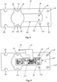
- Fig. 6 shows the load cell from the rear.
- the measuring body 10 is the same as in Fig. 5 aligned. Screws 48 are shown in the fastening holes 36, which serve to screw the load cell with its force absorption section 20 to a fastening device 114.
- the circuit board 42 is screwed with screws 50 in the recess 40 of the measuring body 10 in the holes 34 for the circuit board 42.
- a conductor foil 44 is connected to the circuit board 42, which serves to contact the strain gauges.
- a temperature sensor 46 is attached to the conductor foil 44, which serves for temperature compensation.
- the circuit board 42 or the electronics mounted on the circuit board 42 protrudes into the receptacle 118 of the fastening device 114.
- the fastening device 114 also serves as a spacer between the load cell 102, 104 and the boom 106, so that the circuit board 42 can be accommodated at this distance.
- Fig. 8 shows the force introduction section 24 of a measuring body 10 with an insert 52, which fits positively in the round contour of the holder 32 of the measuring body.
- the insert 52 holds a force transmission element 58.
- Fig. 9 an exploded view of the measuring body 10, the insert 52, the force transmission element 58 and a strut 206 of a shelf base shown in an isometric view.
- the insert 52 is inserted into the holder 32, with the round contour 54 on the underside of the insert 32 coming to rest in a form-fitting manner in the round contour 72 of the holder 32 of the measuring body 10.
- the insert 52 is essentially U-shaped and has a rectangular contour on its inside.
- the width of the insert 52 corresponds to the width 18 of the measuring body 10.
- the force transmission element 58 is also essentially U-shaped, but rotated by 90° about a vertical axis compared to the insert 52. In addition, the force transmission element 58 is rotated by 180° about a horizontal axis compared to the insert 52.
- the force transmission element 58 has a rectangular contour on its inside, which is intended to rest on the rectangular contour of the insert 52.
- the force transmission element 58 is arranged in such a way that its flanks 66 reach over the insert 52 and partially protrude over the measuring body 10, so that the U-shaped structure of the force transmission element 58 prevents the insert 52 from slipping out of the receptacle 32 and the Force transmission element 58 itself in relation to the measuring body 10.
- the force transmission element 58 On its upper side, the force transmission element 58 has a cutting edge 62, that is to say a tapered contact axis for the strut of a shelf base.
- the cutting edge 62 of the force transmission element 58 is aligned parallel to the longitudinal axis 12 of the measuring body 10.
- the flanks 64 of the insert 52 protrude beyond the cutting edge 62 of the force transmission element 58, so that they represent a limitation of the cutting edge along the longitudinal axis 12 of the measuring body 10.
- the flanks 64 of the insert 52 form a limitation for the strut 206 of the shelf base.
- the strut 206 which rests with a recess 208 on the cutting edge 62 of the force transmission element 58 and is weighed, is prevented by the flanks 64 of the insert 52 from sliding over the cutting edge 62 of the force transmission element 58 in the direction of the longitudinal axis 12 of the measuring body 10.
- the strut 206 thus rests without torque on the force introduction section 24 of the load cell 102, 104, which is particularly necessary because the rigid shelf base with its struts 206 rests on four load cells 102, 104 and the force introduction sections 24 of the four load cells 102, 104 must not be alternately braced by the rigid shelf base.
- Fig. 10 shows an isometric top view of the joint section 20 of the measuring body 10 of the load cell 102, 104.
- a strain gauge film 68 with two strain gauges 70 is attached to the thin spots 30 of the upper joint element 26.
- the two strain gauges 70 are connected to two further strain gauges, which are attached to the underside of the lower joint element 28, to form a Wheatstone measuring bridge (bridge circuit).
- the strain gauges 70 are connected to the conductor foil 44 and thus to the circuit board 42 of the load cell via a contact.
- Fig. 11 shows an isometric top view of the joint section of the measuring body 10 of a second variant of the load cell.
- a strain gauge foil 68 with four strain gauges 70 is attached to the thin spots 30 of the upper joint element 26.
- the four strain gauges 70 are connected to the strain gauge foil to form a Wheatstone bridge and are electrically connected to the circuit board 42 via the conductor foil 44.
- the alignment of the meandering resistance tracks of the strain gauges 70 on the upper joint element 26 or on the upper and lower joint elements 26, 28 is always in the direction of the longitudinal axis 12 of the measuring body 10.
- the strain gauges 70 are each aligned in a horizontal direction.
- the surface created by the meandering resistance paths of the strain gauge 70 is horizontal, so that the strain gauges 70 are arranged on the top side of the upper joint element 26 or on the bottom side of the lower joint element 28.
- the orientation of this surface in a Cartesian coordinate system corresponds to the orientation of the narrow long side of the measuring body 10.
- Fig. 12 shows a shelf base 200 designed as a grid shelf base.
- the shelf base 200 comprises a rigid grid structure 202 on which objects in the shelf can be placed.
- the grid structure 202 is supported by at least two struts 206 that run transversely along the shelf base 200 and are located in the front and rear areas of the shelf base 200.
- the struts 206 each have a recess 208 at their ends, with which the struts can be supported without torque on a cutting edge 62 of a force transmission element 58.
- the shelf base can thus be supported on force introduction elements 58 of four load cells 102, 104.
- Fig. 13 shows schematically three shelf areas 211, 213, 215 on a shelf base 200 and corresponding components for inventory monitoring.
- the shelf area 211, 213, 215 from which a product was removed or added to the shelf base 200 is determined by determining the center of gravity of the shelf base 200.
- the shelf base 200 is suspended by the four load cells 261, 262, 263, 264. These are the load cells 102, 104, which are integrated into the shelf brackets 100. A shelf bracket 100 to the left of the shelf base 200 and a shelf bracket 100 to the right of the shelf base 200 support the shelf base 200.
- the load cells 261, 262, 263, 264 support the shelf base 200 at the ends of its struts 206 with their force introduction sections 24.
- the load cells 261, 262, 263, 264 independently determine an effective weight force that is created by the shelf base 200 and the products stored in the shelf areas 211, 213, 215. A single weight force acts on each load cell 261, 262, 263, 264 in proportion to the total weight.
- the data from the load cells 261, 262, 263, 264 are transmitted to an evaluation unit 265.
- the evaluation unit determines the center of gravity coordinates of the shelf base 200 from the individual weight data of the load cells 261, 262, 263, 264.
- the coordinates in the shelf area 211, 213, 215 begin in a corner at the load cell 263 with the coordinates (0, 0) and extend in the horizontal direction X and in the vertical direction Y.
- the load cells 261, 262, 263, 264 are Fig. 13 shown the corresponding weight data W261, W262, W263, W264 are assigned.
- the formation of the center of gravity in the X direction is determined as follows: W 261 + W 262 / W 261 + W 262 + W 263 + W 264
- the formation of the center of gravity in the Y direction is determined as follows: W 261 + W 264 / W 261 + W 262 + W 263 + W 264
- coordinates in the shelf area 211, 213, 215 can be determined that correspond to the center of gravity coordinates of the shelf base 200. These coordinates are determined in the evaluation unit 265 based on the data from the load cells 261, 262, 263, 264. Furthermore, the evaluation unit 265 forms a total weight W261 + W262 + W263 + W264. The center of gravity coordinates and the total weight are transmitted from the evaluation unit 265 to a control device 241.
- the shelf comprises a memory 244 in which an assignment between center of gravity coordinates and shelf areas 211, 213, 215 is stored.
- each shelf area 211, 213, 215 are stored in the memory 244. These do not have to be stored again each time the shelf is filled, as they do not change. However, if the size of the shelf areas 211, 213, 215 and their arrangement are changed by rearranging the partition walls, the assignment between X and Y coordinates and shelf areas 211, 213, 215 must be updated in the memory 244.
- the memory 244 thus stores the X and Y coordinates over which each shelf area 211, 213, 215 extends. Furthermore, a limit value is stored in the memory 244 for each shelf area 211, 213, 215, below which the shelf should issue a message that new goods must be refilled in this shelf area 211, 213, 215.
- an evaluation unit 265 is used to determine from the weight values of the load cells 261, 262, 263, 264 a location at which a product or products were removed or added and the total weight of the removed or added goods.
- the determination in step 231 can be carried out using three alternative methods, which can be explained with reference to Fig. 15 to Fig. 17 are described below.
- the associated shelf area 211, 213, 215 is determined using the control device 241 based on the coordinates of the location where something was removed or added and with the help of the information from the memory 244 about the arrangement of the shelf areas 211, 213, 215.
- step 233 the number of goods that were removed from or added to the shelf area 211, 213, 215 is determined from the determined total weight of the goods removed and the weight value for a good assigned to the shelf area 211, 213, 215 in the memory 244. The number of items removed is therefore determined.
- step 234 the current stock of goods assigned to the shelf area 211, 213, 215 is increased by the number of removed goods is reduced, increased if necessary.
- the method then continues with step 231 with the removal or addition of another item. If a limit value stored in the memory 244 for the inventory in a shelf area 211, 213, 215 is undershot, the method sends a message to an operator in step 235 so that he is informed that the inventory has reached a low level and must be replenished.
- step 236 the operator enters new information about the inventory if he has filled a shelf area 211, 213, 215 with new goods.
- the information in the memory 244 about the inventory in this shelf area 211, 213, 215 is then updated accordingly, prompted by the operator input.
- Fig. 15 shows schematically a first method for determining a location on the shelf base 200 at which an item of goods has been added or removed.
- all load cells 261, 262, 263, 264 are tared, i.e. the shelf base 200 and all goods placed on it are treated as if they were a preload for the load cells 261, 262, 263, 264 and are set to zero.
- a new weight value is measured by at least one load cell 261, 262, 263, 264 and received by the evaluation device 265.
- the evaluation device 265 calculates center of gravity coordinates based on the current weight data of the load cells 261, 262, 263, 264.
- center of gravity coordinates do not reflect the center of gravity of the shelf base 200, but rather the center of gravity of the weight change in the coordinate system of the shelf base 200. This is the location at which an item was removed from or added to the shelf base 200. In step 274, this location and the change in weight are passed on to the control device 241.
- Fig. 16 shows schematically a second method for determining a location on the shelf 200 where a product has been added or removed.
- Center of gravity coordinates are determined from the current center of gravity of the shelf base 200 including all goods placed on it. This is the real center of gravity.
- the shelf base 200 or at least the goods placed on it are not tared.
- a new weight value is measured by at least one load cell 261, 262, 263, 264 and received by the evaluation device 265.
- new center of gravity coordinates are determined by the evaluation device 265 from the new data from the load cells 261, 262, 263, 264.
- step 284 a vector is formed from the previous center of gravity coordinates and the new shear point coordinates, which reflects the shift in the center of gravity coordinates. Starting from the previous center of gravity, the vector leads to the new center of gravity if it is not scaled. Then, in step 285, the vector is scaled using the total weight of the shelf base and the change in the total weight. The location at which a product was removed from or placed on the shelf base 200 is determined in step 286 by adding the scaled vector to the previous center of gravity coordinates. In step 287, this location and the change in weight are passed on to the control device 241.
- Fig. 17 shows schematically a third method for determining a location on the shelf base 200 at which a product was added or removed.
- a weight value is determined by all load cells 261, 262, 263, 264, the previous weight value.
- a new weight value is measured by at least one load cell 261, 262, 263, 264 and received by the evaluation device 265.
- the evaluation unit 265 calculates the change in the weight value separately for each load cell 261, 262, 263, 264, i.e. the evaluation unit calculates the difference between the new weight value and the previous weight value.
- the evaluation device 265 calculates the center of gravity coordinates of the difference values of the four Load cells 261, 262, 263, 264.
- center of gravity coordinates do not reflect the center of gravity of the shelf base 200, but rather the center of gravity of the weight change in the coordinate system of the shelf base 200. This is the location at which an item was removed from or added to the shelf base 200. In step 295, this location and the change in weight are passed on to the control device 241.
- DSP digital signal processor
- ASIC application specific integrated circuit
- FPGA field programmable gate array
- ROM read only memory
- RAM random access memory
Landscapes
- Physics & Mathematics (AREA)
- General Physics & Mathematics (AREA)
- Engineering & Computer Science (AREA)
- Mathematical Physics (AREA)
- Theoretical Computer Science (AREA)
- Aviation & Aerospace Engineering (AREA)
- Measurement Of Force In General (AREA)
- Warehouses Or Storage Devices (AREA)
Claims (14)
- Rayonnage composé d'au moins deux rails de rayonnage disposés verticalement et d'au moins deux consoles de rayonnage (100) disposées à la même hauteur respectivement dans un rail de rayonnage et d'au moins une tablette de rayonnage (200) posée sur les deux consoles de rayonnage (100) disposées à la même hauteur, chaque console de rayonnage comprenant un dispositif d'ancrage (108) destiné à être fixé dans l'un des rails de rayonnage disposés verticalement et une potence (106) destinée à porter la tablette de rayonnage, chaque console de rayonnage comprenant deux cellules de pesage (102, 104), les potences des consoles de rayonnage dépassent des rails de rayonnage dans une direction sensiblement horizontale et chaque potence étant notamment formée par une construction de cadre disposée verticalement ou une tôle disposée verticalement, chaque potence (106) comportant des dispositifs de fixation (114) pour les deux cellules de pesage (102, 104), chaque cellule de pesée (102, 104) possédant un corps de mesure (10) de configuration monolithique qui comprend une portion de réception de force (20), une portion d'introduction de force (24) et une portion d'articulation (22) disposée entre la portion de réception de force (20) et la portion d'introduction de force (24), et
la tablette de rayonnage (200) comprenant deux contrefiches (206) en parallèle, et les portions d'introduction de force (24) des deux cellules de pesage (102, 104) d'une console de rayonnage soutenant respectivement une contrefiche (206) de la tablette de rayonnage (200), caractérisé, en ce que le corps de mesure (10) est à symétrie miroir par rapport au plan horizontal et la portion de réception de force (20) du corps de mesure (10) est montée latéralement sur le dispositif de fixation (114), le corps de mesure (10) possédant au moins un trou de fixation (36) au moyen duquel il est monté sur le dispositif de fixation (114) avec une vis (48) qui suit un tracé horizontal à travers le corps de mesure (10),
et le rayonnage comprenant une unité d'évaluation (265) qui, à intervalles périodiques ou lors d'une modification du poids total, lequel est capté par les quatre cellules de pesage sur les portions d'introduction de force desquelles repose la tablette de rayonnage (200), identifie de nouvelles coordonnées du centre de gravité à partir des données des cellules de pesage (261, 262, 263, 264) et transmet celles-ci à une unité de commande (241), l'unité de commande (241) identifiant une zone de rayonnage (211, 213, 215) sur la base des modifications des coordonnées du centre de gravité, l'unité de commande (41) déterminant, à partir de la modification du poids total, le poids des marchandises prélevées ou ajoutées dans la zone de rayonnage (211, 213, 215) identifiée et actualisant le stock de marchandises stocké dans une mémoire (244) pour cette zone de rayonnage (211, 213, 215) . - Rayonnage selon la revendication 1, caractérisé en ce que le corps de mesure (10) présente un axe longitudinal (12) entre une extrémité axiale côté réception de force et une extrémité axiale côté introduction de force, et en ce que l'axe longitudinal (12) de l'au moins une cellule de pesage montée sur un dispositif de fixation est configuré dans une direction horizontale, la cellule de pesage comprenant au moins une jauge de contrainte (70) disposée dans la zone de la portion d'articulation (24) du côté supérieur ou du inférieur du corps de mesure (10) destinée à capter une déformation d'extension ou de compression du corps de mesure (10), l'au moins une jauge de contrainte (70) étant constituée d'une piste de résistance qui suit un tracé parallèle en forme de méandres, qui est parallèle à l'axe longitudinal (12) du corps de mesure (10) et orientée horizontalement.
- Rayonnage selon l'une des revendications 1 à 2, caractérisée en ce que la portion d'articulation (22) présente au moins un, notamment deux, points minces (30) au niveau d'un élément d'articulation supérieur (26) et présente au moins un, notamment deux, points minces (30) au niveau d'un élément d'articulation inférieur (28) qui suit un tracé parallèle à l'élément d'articulation supérieur (26).
- Rayonnage selon la revendication 3, caractérisé en ce que la cellule de pesage comprend respectivement, dans les zones des deux points minces (39) de l'élément d'articulation supérieur (26), une jauge de contrainte (70) disposée du côté supérieur au niveau de l'élément d'articulation supérieur (26), et en ce que la cellule de pesage comprend respectivement, dans les zones des deux points minces (30) de l'élément d'articulation inférieur (28), une jauge de contrainte (70) disposée du côté inférieur au niveau de l'élément d'articulation inférieur (28), et les quatre jauges de contrainte (70) de la cellule de pesage étant connectées en un pont de mesure de Wheatstone, et notamment la connexion des deux jauges de contrainte (70) disposées du côté supérieur ainsi que les deux jauges de contrainte (70) disposées du côté supérieur étant appliquées sur une feuille de jauge de contrainte (68) et notamment la connexion des deux jauges de contrainte (70) disposées du côté inférieur ainsi que les deux jauges de contrainte (70) disposées du côté inférieur étant appliquées sur une feuille de jauge de contrainte (68).
- Rayonnage selon la revendication 3, caractérisé en ce que la cellule de pesage comprend dans les zones des deux zones minces (30) de l'élément d'articulation supérieur (26) respectivement deux jauges de contrainte (70) disposées du côté supérieur au niveau de l'élément d'articulation supérieur (26), les deux jauges de contrainte (70) respectives étant orientées en parallèle et disposées l'une à côté de l'autre par rapport à un côté étroit (18) du corps de mesure, et les quatre jauges de contrainte (70) de la cellule de pesage étant connectées en un pont de mesure de Wheatstone, et notamment la connexion des jauges de contrainte (70) ainsi que les jauges de contrainte (70) étant appliquées sur une feuille de jauge de contrainte (68).
- Rayonnage selon l'une des revendications 1 à 5, caractérisé en ce que la portion d'introduction de force (24) possède un logement (32) qui est réalisé sous la forme d'une entaille qui part du côté supérieur du corps de mesure (10) et suit un tracé perpendiculairement à l'axe longitudinal.
- Rayonnage selon la revendication 6, caractérisé en ce que l'entaille du logement (32) a un contour rond sur son côté à l'opposé du côté supérieur du corps de mesure et la cellule de pesage comprend un insert (52) qui repose par complémentarité de forme dans le contour rond du logement (32) et l'insert (52) présentant, sur son côté opposé à la complémentarité de forme avec le contour rond, un contour rectangulaire destiné à recevoir un élément de transmission de force (58), et en ce que l'élément de transmission de force (58) est configuré de telle sorte qu'il peut être accueilli avec complémentarité de forme dans le contour rectangulaire de l'insert (52), et en ce que l'élément de transmission de force (58) possède une arête (62) destinée à soutenir une contrefiche (206) de la tablette de rayonnage (200).
- Rayonnage selon l'une des revendications 1 à 7, caractérisé en ce que le corps de mesure (10) présente une longueur (14) le long de son axe longitudinal (12), une hauteur (16) depuis le côté supérieur de l'élément d'articulation côté supérieur (26) jusqu'au côté inférieur de l'élément d'articulation côté inférieur (28) et une largeur (18) dans la dimension qui se trouve perpendiculaire à la longueur et à la hauteur, la largeur (18) du corps de mesure étant comprise entre 3 mm et 40 mm, notamment entre 5 mm et 20 mm, et la longueur (14) du corps de mesure étant de 15 à 25 fois, notamment de 16 à 20 fois, la largeur (18) et la hauteur (16) du corps de mesure étant de 5 à 10 fois, notamment de 6 à 8 fois, la largeur (18) du corps de mesure et en ce que la tôle disposée verticalement est pliée en haut et en bas et les parties pliées dans la direction horizontale recouvrent le corps de mesure ou dépassent de celui-ci dans sa largeur.
- Rayonnage selon l'une des revendications 1 à 8, caractérisé en ce que le corps de mesure (10) comporte au moins trois, notamment quatre trous de fixation (36), lesquels sont réalisés sous forme de perçages et suivent un tracé dans la direction horizontale à travers le corps de mesure (10) et avec lesquels le corps de mesure est vissé au dispositif de fixation (114) et les perçages (36) contenant notamment, sur un côté, des enfoncements (38) qui sont réalisés pour recevoir des têtes fraisées de vis (48).
- Rayonnage selon l'une des revendications 1 à 9, caractérisé en ce que le corps de mesure (10) possède, le long de son axe longitudinal (12), depuis une partie proche de la portion d'articulation de la portion de réception de force (20) jusqu'à la portion d'articulation (22), un renfoncement (40) qui est configuré pour recevoir au moins partiellement une carte de circuit imprimé (42) sur laquelle est disposée une électronique, notamment un convertisseur analogique-numérique destiné au traitement d'au moins un signal de sortie de l'au moins une jauge de contrainte.
- Rayonnage selon l'une des revendications 1 à 10, caractérisé en ce que la console de rayonnage (100) comprend respectivement, des deux côtés de la construction de cadre disposée verticalement ou des deux côtés de la tôle disposée verticalement, deux dispositifs de fixation (114) qui portent chacun une cellule de pesage (102, 104), deux cellules de pesage (102, 104) soutenant respectivement, sur un côté, les contrefiches d'une tablette de rayonnage (200).
- Rayonnage selon l'une des revendications 1 à 11, caractérisé en ce que l'unité d'évaluation (265), lors d'une modification du poids total, identifie un vecteur entre les coordonnées précédentes du centre de gravité et les nouvelles coordonnées du centre de gravité, et en ce que la zone de rayonnage (211, 213, 215) déterminée par l'unité de commande (241) est identifiée par l'unité de commande (241) à partir du vecteur et du poids total.
- Rayonnage selon l'une des revendications 1 à 11, caractérisé en ce que l'unité d'évaluation (265) tare périodiquement et simultanément toutes les cellules de pesage (61, 62, 63, 64).
- Rayonnage selon l'une des revendications 1 à 11, caractérisé en ce que l'unité d'évaluation (265), en vue d'identifier les nouvelles coordonnées du centre de gravité, forme pour chaque cellule de pesage (261, 262, 263, 264) la différence entre une nouvelle valeur de poids et une valeur de poids précédente et identifie les nouvelles coordonnées du centre de gravité à partir des quatre valeurs de différence.
Priority Applications (2)
| Application Number | Priority Date | Filing Date | Title |
|---|---|---|---|
| EP19220148.1A EP3845874B1 (fr) | 2019-12-30 | 2019-12-30 | Étagère |
| US17/123,131 US11607059B2 (en) | 2019-12-30 | 2020-12-16 | Shelf bracket assembly |
Applications Claiming Priority (1)
| Application Number | Priority Date | Filing Date | Title |
|---|---|---|---|
| EP19220148.1A EP3845874B1 (fr) | 2019-12-30 | 2019-12-30 | Étagère |
Publications (2)
| Publication Number | Publication Date |
|---|---|
| EP3845874A1 EP3845874A1 (fr) | 2021-07-07 |
| EP3845874B1 true EP3845874B1 (fr) | 2024-12-04 |
Family
ID=69061172
Family Applications (1)
| Application Number | Title | Priority Date | Filing Date |
|---|---|---|---|
| EP19220148.1A Active EP3845874B1 (fr) | 2019-12-30 | 2019-12-30 | Étagère |
Country Status (2)
| Country | Link |
|---|---|
| US (1) | US11607059B2 (fr) |
| EP (1) | EP3845874B1 (fr) |
Families Citing this family (12)
| Publication number | Priority date | Publication date | Assignee | Title |
|---|---|---|---|---|
| WO2019234692A1 (fr) * | 2018-06-06 | 2019-12-12 | Shekel Scales (2008) Ltd | Systèmes et procédés permettant de peser des produits sur une étagère |
| JP2021526651A (ja) * | 2018-05-16 | 2021-10-07 | シェケル スケールズ(2008)リミテッド | 計量ロードセルおよびそれらを棚において利用する構成 |
| EP3845872B1 (fr) * | 2019-12-30 | 2023-07-12 | Bizerba SE & Co. KG | Cellule de pesage |
| US11326934B1 (en) * | 2020-05-01 | 2022-05-10 | Amazon Technologies, Inc. | Weight sensing apparatus with piezoelectric transducer |
| EP4020417A1 (fr) | 2020-12-27 | 2022-06-29 | Bizerba SE & Co. KG | Magasin à encaissement automatique |
| EP4020418B1 (fr) | 2020-12-27 | 2025-01-29 | Bizerba SE & Co. KG | Magasin à encaissement automatique |
| EP4020415A1 (fr) | 2020-12-27 | 2022-06-29 | Bizerba SE & Co. KG | Magasin à autoencaissement |
| US11399639B1 (en) * | 2021-02-05 | 2022-08-02 | Harbor Freight Tools Usa, Inc. | Self-righting packaging for display of item with aperture |
| US11796378B1 (en) | 2021-06-25 | 2023-10-24 | Amazon Technologies, Inc. | Piezoelectric weight sensing apparatus |
| US12099966B2 (en) * | 2021-11-16 | 2024-09-24 | Digit7 India Private Limited | Device for holding and monitoring weight of product(s) in an inventory management system |
| EP4666042A1 (fr) | 2023-02-18 | 2025-12-24 | DIGI SENS Holding AG | Bras en porte-à-faux pour recevoir et mesurer un poids de charge variable |
| CH720517A2 (de) * | 2023-02-18 | 2024-08-30 | Digi Sens Holding Ag | Kragarm zum Aufnehmen und Messen eines variablen Lastgewichts |
Family Cites Families (34)
| Publication number | Priority date | Publication date | Assignee | Title |
|---|---|---|---|---|
| US4396079A (en) | 1981-07-29 | 1983-08-02 | Sensor Developments, Inc. | Weighing system |
| US4655305A (en) * | 1985-06-24 | 1987-04-07 | Revere Corporation Of America | Strain gage type platform sensor |
| DE3621378A1 (de) * | 1986-06-26 | 1988-01-14 | Erichsen A M Gmbh | Aufnehmer fuer vorrichtungen zum messen von druck-, zug-, scherkraeften oder drehmomenten und verfahren zu seiner herstellung |
| DE3733961A1 (de) | 1987-10-08 | 1989-04-20 | Krups Stiftung | Elektromechanische waage |
| US5293007A (en) | 1992-04-02 | 1994-03-08 | Stress-Tek, Inc. | Method for moment balancing a parallel beam load cell and the article produced thereby |
| JP3314107B2 (ja) | 1993-07-22 | 2002-08-12 | 株式会社イシダ | 加速度センサの取付構造 |
| US5623128A (en) | 1994-03-01 | 1997-04-22 | Mettler-Toledo, Inc. | Load cell with modular calibration components |
| US5510581A (en) | 1994-05-18 | 1996-04-23 | Angel; Shlomo | Mass-produced flat multiple-beam load cell and scales incorporating it |
| KR100191261B1 (ko) * | 1994-07-04 | 1999-06-15 | 구보 미츠오 | 로드셀 유닛 |
| US6318184B1 (en) | 1997-06-02 | 2001-11-20 | The Penn State Research Foundation | Beam strain gauge |
| US6215078B1 (en) | 1998-12-22 | 2001-04-10 | Ncr Corporation | Method and apparatus for determining a stable weight measurement for use in a security software application of a self-service checkout terminal |
| SE515184C2 (sv) | 1999-12-03 | 2001-06-25 | Abb Ab | Lastcell och användning av en lastcell |
| ATE298884T1 (de) * | 2000-09-23 | 2005-07-15 | Digi Sens Ag | Logistik-waage |
| US6817255B2 (en) | 2001-09-12 | 2004-11-16 | The Board Of Trustees Of The University Of Illinois | Apparatus and method for testing of microscale to nanoscale thin films |
| US6789435B2 (en) | 2002-10-01 | 2004-09-14 | Hottinger Baldwin Measurements, Inc. | Hermetically sealed load cell |
| US7240571B2 (en) | 2004-09-30 | 2007-07-10 | Walker Robert R | On-board scale sensor with mechanical amplification and improved output signal apparatus and method |
| US6988412B1 (en) | 2004-11-30 | 2006-01-24 | Endevco Corporation | Piezoresistive strain concentrator |
| ATE446495T1 (de) | 2006-05-30 | 2009-11-15 | Timken Co | Sensor für verschiebung, dehnung und kraft |
| ATE554371T1 (de) | 2008-05-15 | 2012-05-15 | Mettler Toledo Ag | Gekapselte wägezelle mit eckenlasteinstellung |
| DE102008056715B4 (de) | 2008-11-11 | 2010-09-23 | Sartorius Ag | Kraftmessplatte |
| KR100919478B1 (ko) | 2009-06-16 | 2009-09-28 | 박흥준 | 편심 오차를 극복하기 위한 유도 전압을 이용한 하중 측정 트랜스듀서 및 그 트랜스듀서를 이용한 하중 측정 시스템 |
| US8935964B2 (en) | 2012-12-17 | 2015-01-20 | Tyco Electronics Corporation | Transducer for and method of measuring normal force of a compliant pin |
| WO2014127427A1 (fr) | 2013-02-22 | 2014-08-28 | Breakaway Innovations Pty Ltd | Module électronique pour manivelle de pédalier |
| JP5728745B2 (ja) | 2013-03-27 | 2015-06-03 | 株式会社タニタ | 起歪体、ロードセルおよび重量測定装置 |
| US10121121B1 (en) * | 2015-12-28 | 2018-11-06 | Amazon Technologies, Inc. | Smart shelves |
| US10198710B1 (en) | 2016-03-28 | 2019-02-05 | Amazon Technologies, Inc. | System to determine a change in weight at a load cell |
| DE102017104367A1 (de) * | 2017-03-02 | 2018-09-06 | Bizerba SE & Co. KG | Wägezelle für eine Waage |
| US10746589B1 (en) * | 2017-06-21 | 2020-08-18 | Amazon Technologies, Inc. | Crossbar mechanism for coupling to fixture |
| US10809122B1 (en) * | 2017-06-21 | 2020-10-20 | Amazon Technologies, Inc. | Components of weighing module and mechanism for coupling to fixture |
| JP2021526651A (ja) | 2018-05-16 | 2021-10-07 | シェケル スケールズ(2008)リミテッド | 計量ロードセルおよびそれらを棚において利用する構成 |
| US10969267B1 (en) * | 2019-03-01 | 2021-04-06 | Amazon Technologies, Inc. | Parallel planar weight sensing device |
| US11125607B1 (en) * | 2019-05-30 | 2021-09-21 | Amazon Technologies, Inc. | Integrated multi-lane weight measuring device |
| CN110169685A (zh) * | 2019-07-04 | 2019-08-27 | 深圳市尤鸟信息技术有限公司 | 一种多功能层板货架 |
| EP3845873B1 (fr) * | 2019-12-30 | 2023-02-15 | Bizerba SE & Co. KG | Console d'étagère |
-
2019
- 2019-12-30 EP EP19220148.1A patent/EP3845874B1/fr active Active
-
2020
- 2020-12-16 US US17/123,131 patent/US11607059B2/en active Active
Also Published As
| Publication number | Publication date |
|---|---|
| US11607059B2 (en) | 2023-03-21 |
| EP3845874A1 (fr) | 2021-07-07 |
| US20210196059A1 (en) | 2021-07-01 |
Similar Documents
| Publication | Publication Date | Title |
|---|---|---|
| EP3845874B1 (fr) | Étagère | |
| EP3845873B1 (fr) | Console d'étagère | |
| DE60303032T2 (de) | Lagersystem | |
| DE3246006A1 (de) | Wiegen | |
| EP3620760B1 (fr) | Dispositif de vente à surveillance de l'inventaire intégrée | |
| EP2178035A1 (fr) | Procédé et agencement de mesure de pièce vide pour des pièces de stockage ou de transport | |
| DE102005019275A1 (de) | Untersuchungsvorrichtung für einen Treibriemen eines kontinuierlich veränderlichen Getriebes | |
| EP3845872B1 (fr) | Cellule de pesage | |
| WO2010054749A1 (fr) | Plaque de mesure de force | |
| DE102008048367C5 (de) | Lagervorrichtung mit Überstandskontrolle | |
| EP0166168A1 (fr) | Balance pour mesurer la charge d'une roue | |
| DE102004028979A1 (de) | Fahrzeuggewicht-Messvorrichtung | |
| EP1570962A1 (fr) | Machine et méthode à découper des produits alimentaires | |
| WO2025068009A1 (fr) | Procédé de stockage d'articles dans un appareil de préparation de commandes, et appareil de préparation de commandes | |
| DE2946175C2 (fr) | ||
| EP0187784B1 (fr) | Dispositif d'essai pour elements en forme de barre, en particulier un segment d'ossature porteuse d'un ouvrage d'art | |
| WO2009074171A1 (fr) | Procédé et dispositif de pesage de produits | |
| DE102005033952B4 (de) | Messeinrichtung | |
| DE4301460C2 (de) | Regal | |
| DE202024101650U1 (de) | Messvorrichtung für Pakete | |
| DE7732143U1 (de) | Innenwandverkleidung fuer einen Transportbehaelter oder Fahrzeugaufbau | |
| DE19835031A1 (de) | Lagergutträger | |
| CH720517A2 (de) | Kragarm zum Aufnehmen und Messen eines variablen Lastgewichts | |
| EP1092366A1 (fr) | Rayonnage | |
| DE2237661A1 (de) | Verfahren und vorrichtung zur kraftmessung |
Legal Events
| Date | Code | Title | Description |
|---|---|---|---|
| PUAI | Public reference made under article 153(3) epc to a published international application that has entered the european phase |
Free format text: ORIGINAL CODE: 0009012 |
|
| STAA | Information on the status of an ep patent application or granted ep patent |
Free format text: STATUS: THE APPLICATION HAS BEEN PUBLISHED |
|
| AK | Designated contracting states |
Kind code of ref document: A1 Designated state(s): AL AT BE BG CH CY CZ DE DK EE ES FI FR GB GR HR HU IE IS IT LI LT LU LV MC MK MT NL NO PL PT RO RS SE SI SK SM TR |
|
| STAA | Information on the status of an ep patent application or granted ep patent |
Free format text: STATUS: REQUEST FOR EXAMINATION WAS MADE |
|
| 17P | Request for examination filed |
Effective date: 20211208 |
|
| RBV | Designated contracting states (corrected) |
Designated state(s): AL AT BE BG CH CY CZ DE DK EE ES FI FR GB GR HR HU IE IS IT LI LT LU LV MC MK MT NL NO PL PT RO RS SE SI SK SM TR |
|
| STAA | Information on the status of an ep patent application or granted ep patent |
Free format text: STATUS: EXAMINATION IS IN PROGRESS |
|
| 17Q | First examination report despatched |
Effective date: 20230327 |
|
| GRAP | Despatch of communication of intention to grant a patent |
Free format text: ORIGINAL CODE: EPIDOSNIGR1 |
|
| STAA | Information on the status of an ep patent application or granted ep patent |
Free format text: STATUS: GRANT OF PATENT IS INTENDED |
|
| INTG | Intention to grant announced |
Effective date: 20240918 |
|
| GRAS | Grant fee paid |
Free format text: ORIGINAL CODE: EPIDOSNIGR3 |
|
| GRAA | (expected) grant |
Free format text: ORIGINAL CODE: 0009210 |
|
| STAA | Information on the status of an ep patent application or granted ep patent |
Free format text: STATUS: THE PATENT HAS BEEN GRANTED |
|
| AK | Designated contracting states |
Kind code of ref document: B1 Designated state(s): AL AT BE BG CH CY CZ DE DK EE ES FI FR GB GR HR HU IE IS IT LI LT LU LV MC MK MT NL NO PL PT RO RS SE SI SK SM TR |
|
| REG | Reference to a national code |
Ref country code: GB Ref legal event code: FG4D Free format text: NOT ENGLISH |
|
| REG | Reference to a national code |
Ref country code: CH Ref legal event code: EP |
|
| REG | Reference to a national code |
Ref country code: DE Ref legal event code: R096 Ref document number: 502019012590 Country of ref document: DE |
|
| REG | Reference to a national code |
Ref country code: IE Ref legal event code: FG4D Free format text: LANGUAGE OF EP DOCUMENT: GERMAN |
|
| REG | Reference to a national code |
Ref country code: LT Ref legal event code: MG9D |
|
| REG | Reference to a national code |
Ref country code: NL Ref legal event code: MP Effective date: 20241204 |
|
| PG25 | Lapsed in a contracting state [announced via postgrant information from national office to epo] |
Ref country code: HR Free format text: LAPSE BECAUSE OF FAILURE TO SUBMIT A TRANSLATION OF THE DESCRIPTION OR TO PAY THE FEE WITHIN THE PRESCRIBED TIME-LIMIT Effective date: 20241204 |
|
| PG25 | Lapsed in a contracting state [announced via postgrant information from national office to epo] |
Ref country code: FI Free format text: LAPSE BECAUSE OF FAILURE TO SUBMIT A TRANSLATION OF THE DESCRIPTION OR TO PAY THE FEE WITHIN THE PRESCRIBED TIME-LIMIT Effective date: 20241204 |
|
| PG25 | Lapsed in a contracting state [announced via postgrant information from national office to epo] |
Ref country code: BG Free format text: LAPSE BECAUSE OF FAILURE TO SUBMIT A TRANSLATION OF THE DESCRIPTION OR TO PAY THE FEE WITHIN THE PRESCRIBED TIME-LIMIT Effective date: 20241204 |
|
| PG25 | Lapsed in a contracting state [announced via postgrant information from national office to epo] |
Ref country code: ES Free format text: LAPSE BECAUSE OF FAILURE TO SUBMIT A TRANSLATION OF THE DESCRIPTION OR TO PAY THE FEE WITHIN THE PRESCRIBED TIME-LIMIT Effective date: 20241204 |
|
| PG25 | Lapsed in a contracting state [announced via postgrant information from national office to epo] |
Ref country code: NO Free format text: LAPSE BECAUSE OF FAILURE TO SUBMIT A TRANSLATION OF THE DESCRIPTION OR TO PAY THE FEE WITHIN THE PRESCRIBED TIME-LIMIT Effective date: 20250304 |
|
| PG25 | Lapsed in a contracting state [announced via postgrant information from national office to epo] |
Ref country code: LV Free format text: LAPSE BECAUSE OF FAILURE TO SUBMIT A TRANSLATION OF THE DESCRIPTION OR TO PAY THE FEE WITHIN THE PRESCRIBED TIME-LIMIT Effective date: 20241204 Ref country code: GR Free format text: LAPSE BECAUSE OF FAILURE TO SUBMIT A TRANSLATION OF THE DESCRIPTION OR TO PAY THE FEE WITHIN THE PRESCRIBED TIME-LIMIT Effective date: 20250305 |
|
| PG25 | Lapsed in a contracting state [announced via postgrant information from national office to epo] |
Ref country code: RS Free format text: LAPSE BECAUSE OF FAILURE TO SUBMIT A TRANSLATION OF THE DESCRIPTION OR TO PAY THE FEE WITHIN THE PRESCRIBED TIME-LIMIT Effective date: 20250304 |
|
| PG25 | Lapsed in a contracting state [announced via postgrant information from national office to epo] |
Ref country code: NL Free format text: LAPSE BECAUSE OF FAILURE TO SUBMIT A TRANSLATION OF THE DESCRIPTION OR TO PAY THE FEE WITHIN THE PRESCRIBED TIME-LIMIT Effective date: 20241204 |
|
| PG25 | Lapsed in a contracting state [announced via postgrant information from national office to epo] |
Ref country code: SM Free format text: LAPSE BECAUSE OF FAILURE TO SUBMIT A TRANSLATION OF THE DESCRIPTION OR TO PAY THE FEE WITHIN THE PRESCRIBED TIME-LIMIT Effective date: 20241204 |
|
| PG25 | Lapsed in a contracting state [announced via postgrant information from national office to epo] |
Ref country code: PL Free format text: LAPSE BECAUSE OF FAILURE TO SUBMIT A TRANSLATION OF THE DESCRIPTION OR TO PAY THE FEE WITHIN THE PRESCRIBED TIME-LIMIT Effective date: 20241204 |
|
| PG25 | Lapsed in a contracting state [announced via postgrant information from national office to epo] |
Ref country code: IS Free format text: LAPSE BECAUSE OF FAILURE TO SUBMIT A TRANSLATION OF THE DESCRIPTION OR TO PAY THE FEE WITHIN THE PRESCRIBED TIME-LIMIT Effective date: 20250404 |
|
| PG25 | Lapsed in a contracting state [announced via postgrant information from national office to epo] |
Ref country code: PT Free format text: LAPSE BECAUSE OF FAILURE TO SUBMIT A TRANSLATION OF THE DESCRIPTION OR TO PAY THE FEE WITHIN THE PRESCRIBED TIME-LIMIT Effective date: 20250404 |
|
| PG25 | Lapsed in a contracting state [announced via postgrant information from national office to epo] |
Ref country code: EE Free format text: LAPSE BECAUSE OF FAILURE TO SUBMIT A TRANSLATION OF THE DESCRIPTION OR TO PAY THE FEE WITHIN THE PRESCRIBED TIME-LIMIT Effective date: 20241204 |
|
| PG25 | Lapsed in a contracting state [announced via postgrant information from national office to epo] |
Ref country code: RO Free format text: LAPSE BECAUSE OF FAILURE TO SUBMIT A TRANSLATION OF THE DESCRIPTION OR TO PAY THE FEE WITHIN THE PRESCRIBED TIME-LIMIT Effective date: 20241204 |
|
| PG25 | Lapsed in a contracting state [announced via postgrant information from national office to epo] |
Ref country code: SK Free format text: LAPSE BECAUSE OF FAILURE TO SUBMIT A TRANSLATION OF THE DESCRIPTION OR TO PAY THE FEE WITHIN THE PRESCRIBED TIME-LIMIT Effective date: 20241204 |
|
| PG25 | Lapsed in a contracting state [announced via postgrant information from national office to epo] |
Ref country code: CZ Free format text: LAPSE BECAUSE OF FAILURE TO SUBMIT A TRANSLATION OF THE DESCRIPTION OR TO PAY THE FEE WITHIN THE PRESCRIBED TIME-LIMIT Effective date: 20241204 |
|
| PG25 | Lapsed in a contracting state [announced via postgrant information from national office to epo] |
Ref country code: IT Free format text: LAPSE BECAUSE OF FAILURE TO SUBMIT A TRANSLATION OF THE DESCRIPTION OR TO PAY THE FEE WITHIN THE PRESCRIBED TIME-LIMIT Effective date: 20241204 |
|
| REG | Reference to a national code |
Ref country code: CH Ref legal event code: PL |
|
| PG25 | Lapsed in a contracting state [announced via postgrant information from national office to epo] |
Ref country code: LU Free format text: LAPSE BECAUSE OF NON-PAYMENT OF DUE FEES Effective date: 20241230 |
|
| REG | Reference to a national code |
Ref country code: DE Ref legal event code: R097 Ref document number: 502019012590 Country of ref document: DE |
|
| PG25 | Lapsed in a contracting state [announced via postgrant information from national office to epo] |
Ref country code: SE Free format text: LAPSE BECAUSE OF FAILURE TO SUBMIT A TRANSLATION OF THE DESCRIPTION OR TO PAY THE FEE WITHIN THE PRESCRIBED TIME-LIMIT Effective date: 20241204 |
|
| PG25 | Lapsed in a contracting state [announced via postgrant information from national office to epo] |
Ref country code: MC Free format text: LAPSE BECAUSE OF FAILURE TO SUBMIT A TRANSLATION OF THE DESCRIPTION OR TO PAY THE FEE WITHIN THE PRESCRIBED TIME-LIMIT Effective date: 20241204 |
|
| REG | Reference to a national code |
Ref country code: BE Ref legal event code: MM Effective date: 20241231 |
|
| PG25 | Lapsed in a contracting state [announced via postgrant information from national office to epo] |
Ref country code: DK Free format text: LAPSE BECAUSE OF FAILURE TO SUBMIT A TRANSLATION OF THE DESCRIPTION OR TO PAY THE FEE WITHIN THE PRESCRIBED TIME-LIMIT Effective date: 20241204 |
|
| PLBE | No opposition filed within time limit |
Free format text: ORIGINAL CODE: 0009261 |
|
| STAA | Information on the status of an ep patent application or granted ep patent |
Free format text: STATUS: NO OPPOSITION FILED WITHIN TIME LIMIT |
|
| PG25 | Lapsed in a contracting state [announced via postgrant information from national office to epo] |
Ref country code: BE Free format text: LAPSE BECAUSE OF NON-PAYMENT OF DUE FEES Effective date: 20241231 |
|
| PG25 | Lapsed in a contracting state [announced via postgrant information from national office to epo] |
Ref country code: CH Free format text: LAPSE BECAUSE OF NON-PAYMENT OF DUE FEES Effective date: 20241231 |
|
| PG25 | Lapsed in a contracting state [announced via postgrant information from national office to epo] |
Ref country code: IE Free format text: LAPSE BECAUSE OF NON-PAYMENT OF DUE FEES Effective date: 20241230 |
|
| 26N | No opposition filed |
Effective date: 20250905 |
|
| PGFP | Annual fee paid to national office [announced via postgrant information from national office to epo] |
Ref country code: GB Payment date: 20251218 Year of fee payment: 7 |
|
| PGFP | Annual fee paid to national office [announced via postgrant information from national office to epo] |
Ref country code: FR Payment date: 20251218 Year of fee payment: 7 |
|
| REG | Reference to a national code |
Ref country code: AT Ref legal event code: MM01 Ref document number: 1748612 Country of ref document: AT Kind code of ref document: T Effective date: 20241230 |
|
| PGFP | Annual fee paid to national office [announced via postgrant information from national office to epo] |
Ref country code: DE Payment date: 20251222 Year of fee payment: 7 |
|
| PG25 | Lapsed in a contracting state [announced via postgrant information from national office to epo] |
Ref country code: AT Free format text: LAPSE BECAUSE OF NON-PAYMENT OF DUE FEES Effective date: 20241230 |