EP3845877A1 - Module de pesage et sa structure d'étalonnage interne - Google Patents
Module de pesage et sa structure d'étalonnage interne Download PDFInfo
- Publication number
- EP3845877A1 EP3845877A1 EP20213066.2A EP20213066A EP3845877A1 EP 3845877 A1 EP3845877 A1 EP 3845877A1 EP 20213066 A EP20213066 A EP 20213066A EP 3845877 A1 EP3845877 A1 EP 3845877A1
- Authority
- EP
- European Patent Office
- Prior art keywords
- internal calibration
- support frame
- calibration weight
- load
- weight support
- Prior art date
- Legal status (The legal status is an assumption and is not a legal conclusion. Google has not performed a legal analysis and makes no representation as to the accuracy of the status listed.)
- Granted
Links
Images

Classifications
-
- G—PHYSICS
- G01—MEASURING; TESTING
- G01G—WEIGHING
- G01G23/00—Auxiliary devices for weighing apparatus
- G01G23/01—Testing or calibrating of weighing apparatus
- G01G23/012—Testing or calibrating of weighing apparatus with load cells comprising in-build calibration weights
Definitions
- the present invention relates to an internal calibration mechanism suitable for a balance, especially for a weigh module in an electronic balance.
- the weigh module with a greater weighing range correspondingly requires an internal calibration weight with greater mass.
- the size of the internal calibration weight is required not to be excessively large. In this case, the weight and size of the internal calibration weight are limited, so that the corresponding mass during internal calibration cannot meet weighing performance requirements of internal calibration of the weigh module.
- the technical problem to be solved by the present invention is to provide an internal calibration mechanism to solve the problem that in the prior art, the mass and size of an internal calibration weight of an internal calibration mechanism of an electronic balance are limited.
- the internal calibration driving structure and the internal calibration weight are mechanisms for loading the internal calibration weight on the support frame or unloading the internal calibration weight from the support frame in the prior art, which is not repeated herein.
- no restriction is imposed on the structure and form of the internal calibration driving structure and the internal calibration weight.
- the internal calibration weight support frame and the load-receiving portion implement force transmission through the flexure hinge or by making their joint into a slice-like shape such as by means of cutting.
- the internal calibration weight support frame and the fixing portion implement a fulcrum function of a lever through the flexure hinge or by making their joint into a slice-like shape such as by means of cutting.
- the internal calibration structure of this solution amplifies the force of the internal calibration weight on the weigh module by using the lever principle, and a simpler and more compact internal calibration structure is also achieved.
- integrated forming can further reduce assembly parts, and processing, assembly, logistics and other costs also become lower.
- the load-receiving portion, a parallel guide portion, the fixing portion and a lever of the weigh module are integrally formed.
- the main body portion of the whole weigh module is integrally formed, which reduces types of parts of the weigh module and reduces costs of processing, assembly, logistics, etc.
- the types of parts of the weigh module can be simplified and the costs of processing, assembly, logistics, etc. are further reduced.
- the opening or the groove of the internal calibration weight support frame is a V-shaped opening or groove.
- the opening or the groove is designed as a V shape, which can stably load the internal calibration weight and prevent the internal calibration weight from shaking on the support frame.
- force transmission connecting portion and the fulcrum connecting portion are respectively fixed to the load-receiving portion and the fixing portion by rivets or welding.
- a length from a centre line of the opening or the groove of the support frame to the joint between the internal calibration weight support frame and the fixing portion is greater than a length from the joint between the internal calibration weight support frame and the load-receiving portion to the joint between the internal calibration weight support frame and the fixing portion.
- a weigh module is further provided, comprising the foregoing internal calibration mechanism.
- the positive improvement effects of the present invention are as follows: according to the foregoing solution, an internal calibration weight with a smaller size can be obtained, and the power, size, etc. of a corresponding internal calibration motor can be made very small, so that the structure of the sensor is simple and compact, the size of the whole sensor is effectively reduced, and the calibration weighing performance is improved.
- the self-calibration weight which is many times heavier than the self-weight of the internal calibration weight can be obtained through an amplification action of a lever mechanism, so that the problem that the internal calibration weight with a large weight is needed due to the limitation of size, space, etc. is solved.
- a weigh module 1 comprises a load-receiving portion 11, a fixing portion 12, a parallel guide portion 13, a lever 14, a magnetic system structure 15, and an internal calibration mechanism 16.
- the load-receiving portion 11, the parallel guide portion 13, the fixing portion 12 and the lever 14 are of an integrated structure, and are integrally formed by a whole piece of material.
- the integrated structure of this embodiment may be formed by die-casting, or by machining, or by die-casting and machining.
- the internal calibration mechanism 16 of this embodiment comprises an internal calibration driving structure 161, an internal calibration weight 162, and an internal calibration weight support frame 163.
- the internal calibration weight support frame 163 is provided with a V-shaped groove to load or place the internal calibration weight 162.
- the internal calibration weight support frame 163 in this embodiment is symmetrically arranged at both sides of the weigh module 1, and the internal calibration driving mechanism 161 can lift the internal calibration weight 162 in a vertical direction on Fig.2 and place the internal calibration weight onto the internal calibration weight support frame 163 for internal calibration. After the internal calibration is finished, the internal calibration driving mechanism 161 can also lift the internal calibration weight 162 away from the internal calibration weight support frame 163 in the vertical direction.
- the internal calibration weight 162 thus has a calibrated state and an uncalibrated state in the weigh module.
- the internal calibration weight 162 is put down by the internal calibration driving mechanism 161 and placed on the internal calibration weight support frame 163, and then the internal calibration driving mechanism 161 is reset; and in this case, a gap is formed between the internal calibration weight 162 and the internal calibration driving machine 161 in the vertical direction in Fig2 , that is, the internal calibration weight 162 is separated from the internal calibration driving mechanism 161.
- the internal calibration driving mechanism 161 lifted up the internal calibration weight 162, the internal calibration weight 162 is placed on the internal calibration driving mechanism 161, and a gap is formed between the internal calibration weight support frame 163 and the internal calibration weight 162 in the vertical direction in Fig.2 , that is, the internal calibration weight support frame 163 is separated from the internal calibration weight 162.
- the internal calibration weight support frame 163 comprises an internal calibration weight support portion 1631 configured to place the internal calibration weight 162 for internal calibration, a body portion of an internal calibration weight support frame 1632, and a connecting portion of an internal calibration weight support frame 1633 that is connected to the load-receiving portion 11 of the weigh module, wherein a joint between the connecting portion of the internal calibration weight support frame 1633 and the load-receiving portion 11 is cut into an flexure hinge to implement force transmission.
- the function of the flexure hinge is the same as that of a connecting flexure hinge in the weigh module assembled in the prior art, which is not repeated herein.
- a fulcrum portion of an internal calibration weight support frame 1634 where the connecting portion of the internal calibration weight support frame 1633 is connected to an extension portion of the fixing portion 12 is cut into an flexure hinge to play a role of a lever supporting point; and the function of the flexure hinge is the same as that of a fulcrum connecting flexure hinge in the weigh module assembled in the prior art, which is not repeated herein.
- the internal calibration mechanism 16, the load-receiving portion 11, the parallel guide portion 13, the fixing portion 12 and the lever 14 are of an integrated structure, and are integrally formed by a whole piece of material. Integrated processing can reduce the types of parts, thereby effectively reducing costs of parts processing, transportation, storage, etc.
- the sensor has good consistency in performance and is convenient to assemble, and the assembly efficiency can be improved.
- a distance between a weight support centre of the internal calibration weight support portion 1631 and the fulcrum portion of the internal calibration weight support frame 1634 that is connected to the fixing portion 12 is a
- a distance between the connecting portion of the internal calibration weight support frame 1633 and the fulcrum portion of the internal calibration weight support frame 1634 that is connected to the fixing portion 12 is b.
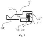
- internal calibration weight support frames 163' are of a separated structure. As shown in Fig. 3 , the internal calibration weight support frame 163' comprises an internal calibration weight support portion 1631', a body portion of an internal calibration weight support frame 1632', a connecting portion of an internal calibration weight support frame 1633', a fulcrum portion of an internal calibration weight support frame 1634', a connecting portion 1635' connected to the load-receiving portion 11, and a connecting portion 1636' connected to the fixing portion 12.
- Thin sheet structures between components of the internal calibration weight support frame 163' in this embodiment replace connecting flexure hinges and fulcrum flexure hinges, reduce the types of parts and facilitate assembly.
- the internal calibration weight support frame 163', the load-receiving portion 11 and the fixing portion 12 are in fixed connection, such as screw connection, riveting, welding and other connection manners.
- the internal calibration weight support frames 163' of this embodiment are of a separated structure, which can reduce the processing difficulty and processing cost, and can also meet requirements for high performance of the weigh module.
Landscapes
- Physics & Mathematics (AREA)
- General Physics & Mathematics (AREA)
- Measurement Of Force In General (AREA)
- Measuring Volume Flow (AREA)
- Measuring Fluid Pressure (AREA)
- Electric Ovens (AREA)
Applications Claiming Priority (1)
| Application Number | Priority Date | Filing Date | Title |
|---|---|---|---|
| CN201911414983.2A CN113124984B (zh) | 2019-12-31 | 2019-12-31 | 称重传感器及其内校结构 |
Publications (2)
| Publication Number | Publication Date |
|---|---|
| EP3845877A1 true EP3845877A1 (fr) | 2021-07-07 |
| EP3845877B1 EP3845877B1 (fr) | 2026-01-28 |
Family
ID=73793057
Family Applications (1)
| Application Number | Title | Priority Date | Filing Date |
|---|---|---|---|
| EP20213066.2A Active EP3845877B1 (fr) | 2019-12-31 | 2020-12-10 | Module de pesage avec structure d'étalonnage interne |
Country Status (3)
| Country | Link |
|---|---|
| US (1) | US11933663B2 (fr) |
| EP (1) | EP3845877B1 (fr) |
| CN (1) | CN113124984B (fr) |
Cited By (1)
| Publication number | Priority date | Publication date | Assignee | Title |
|---|---|---|---|---|
| WO2023006053A1 (fr) * | 2021-07-29 | 2023-02-02 | Mettler-Toledo (Changzhou) Precision Instruments Ltd. | Module de pesage intégré de haute précision |
Families Citing this family (2)
| Publication number | Priority date | Publication date | Assignee | Title |
|---|---|---|---|---|
| DE102019130625A1 (de) * | 2019-11-13 | 2021-05-20 | Minebea Intec Aachen GmbH & Co. KG | Wägeaufnehmer mit einer Justiergewichtsschaltung |
| CN116007732B (zh) * | 2021-10-21 | 2025-06-13 | 梅特勒-托利多仪器(上海)有限公司 | 自校准传感器及包括其的称量装置 |
Citations (1)
| Publication number | Priority date | Publication date | Assignee | Title |
|---|---|---|---|---|
| WO2002037065A1 (fr) * | 2000-11-04 | 2002-05-10 | Sartorius Ag | Capteur de pesage avec poids d'ajustage |
Family Cites Families (16)
| Publication number | Priority date | Publication date | Assignee | Title |
|---|---|---|---|---|
| US5866854A (en) * | 1996-02-12 | 1999-02-02 | Mettler-Toledo Ag | Calibrating device for a balance |
| US5753792A (en) * | 1996-09-16 | 1998-05-19 | Olson; Robert | Static and dynamic motion weight measuring apparatus |
| DE19729623B4 (de) * | 1997-07-10 | 2004-10-07 | Mettler-Toledo Gmbh | Anordnung zum Befestigen einer Parallelogrammführung in einer Kraftmeßvorrichtung |
| DE19820637A1 (de) * | 1998-05-08 | 1999-11-11 | Mettler Toledo Gmbh | Waage mit einem Ankopplungsbereich für ein Kalibriergewicht |
| US6414252B1 (en) * | 1998-11-16 | 2002-07-02 | Mettler-Toledo Gmbh | Calibration system for a weighing scale |
| DE19923207C1 (de) * | 1999-05-20 | 2000-10-12 | Sartorius Gmbh | Wägeaufnehmer |
| DE10024017B4 (de) * | 1999-05-20 | 2007-11-22 | Sartorius Ag | Wägeaufnehmer mit mehreren Übersetzungshebeln |
| ATE349000T1 (de) * | 2004-02-12 | 2007-01-15 | Mettler Toledo Ag | Wägezellenmodul |
| DE502004006067D1 (de) * | 2004-12-23 | 2008-03-13 | Mettler Toledo Gmbh | Kalibriergewichtsanordnung für eine elektronische Waage |
| DE202005017241U1 (de) * | 2005-11-04 | 2006-02-16 | Sauer, Sebastian | Mobile Radlastwaage |
| DE102009015284B4 (de) * | 2009-04-01 | 2015-05-21 | Wipotec Wiege- Und Positioniersysteme Gmbh | Wägesensoreinheit, insbesondere monolithische Wägesensoreinheit für eine nach dem Prinzip der elektromagnetischen Kraftkompensation arbeitende Wägevorrichtung |
| CN204115853U (zh) * | 2014-10-23 | 2015-01-21 | 奥豪斯仪器(常州)有限公司 | 电子天平内校机构 |
| CN106197624B (zh) * | 2015-05-26 | 2019-02-26 | 梅特勒-托利多仪器(上海)有限公司 | 称重传感器以及电子天平 |
| JP6752725B2 (ja) * | 2015-05-26 | 2020-09-09 | メトラー−トレド ゲーエムベーハー | 平行ガイド機構モジュールを有する秤量モジュール |
| DE102019130625A1 (de) * | 2019-11-13 | 2021-05-20 | Minebea Intec Aachen GmbH & Co. KG | Wägeaufnehmer mit einer Justiergewichtsschaltung |
| CN211783821U (zh) * | 2019-12-31 | 2020-10-27 | 梅特勒-托利多仪器(上海)有限公司 | 称重传感器及其内校机构 |
-
2019
- 2019-12-31 CN CN201911414983.2A patent/CN113124984B/zh active Active
-
2020
- 2020-12-10 EP EP20213066.2A patent/EP3845877B1/fr active Active
- 2020-12-15 US US17/247,521 patent/US11933663B2/en active Active
Patent Citations (1)
| Publication number | Priority date | Publication date | Assignee | Title |
|---|---|---|---|---|
| WO2002037065A1 (fr) * | 2000-11-04 | 2002-05-10 | Sartorius Ag | Capteur de pesage avec poids d'ajustage |
Cited By (1)
| Publication number | Priority date | Publication date | Assignee | Title |
|---|---|---|---|---|
| WO2023006053A1 (fr) * | 2021-07-29 | 2023-02-02 | Mettler-Toledo (Changzhou) Precision Instruments Ltd. | Module de pesage intégré de haute précision |
Also Published As
| Publication number | Publication date |
|---|---|
| CN113124984A (zh) | 2021-07-16 |
| US11933663B2 (en) | 2024-03-19 |
| CN113124984B (zh) | 2026-02-10 |
| EP3845877B1 (fr) | 2026-01-28 |
| US20210199491A1 (en) | 2021-07-01 |
Similar Documents
| Publication | Publication Date | Title |
|---|---|---|
| EP3845877A1 (fr) | Module de pesage et sa structure d'étalonnage interne | |
| RU2495817C2 (ru) | Весы вилочного погрузчика | |
| US9073738B2 (en) | Reduced load offset loss integrated lift truck attachment | |
| US20030010542A1 (en) | Portable weigh scale system for use with vehicles having lift truck forks or the like | |
| JP5036134B2 (ja) | ロードセル及び秤 | |
| EP3721184B1 (fr) | Capteur de pesée et balance électronique | |
| CN211783821U (zh) | 称重传感器及其内校机构 | |
| CN212158815U (zh) | 称重传感器及其内校结构 | |
| JPS6232324A (ja) | マルチレンジロ−ドセル秤 | |
| ATE340355T1 (de) | Wiegeeinrichtung | |
| EP3845875A1 (fr) | Modules de pesage | |
| CN109870226A (zh) | 称重传感器及其杠杆 | |
| CN217901004U (zh) | 具有过载保护功能的承载托架及其称重传感器 | |
| EP1715311B1 (fr) | Méchanisme de transfert de charge | |
| CN212158768U (zh) | 称重传感器及包括其的电子天平 | |
| EP1666853A3 (fr) | Dispositif pour peser une charge | |
| RU110185U1 (ru) | Крановые весы | |
| WO2024149295A1 (fr) | Cellule de charge ayant un mécanisme anti-chute de transport, et balance électronique la comprenant | |
| JP4012692B2 (ja) | 計量セル用支持装置およびこの支持装置を備えた秤 | |
| US8770044B2 (en) | Load detection sensor | |
| CN210603536U (zh) | 一种双层缓冲地磅 | |
| CN222379187U (zh) | 带有分离托盘的称重装置 | |
| CN214748369U (zh) | 一种高结构强度汽车衡秤体 | |
| CN211452550U (zh) | 称量单元及包括其的称量传感器 | |
| JPS6282328A (ja) | ロバ−バル機構に改良を加えた電子天秤 |
Legal Events
| Date | Code | Title | Description |
|---|---|---|---|
| PUAI | Public reference made under article 153(3) epc to a published international application that has entered the european phase |
Free format text: ORIGINAL CODE: 0009012 |
|
| STAA | Information on the status of an ep patent application or granted ep patent |
Free format text: STATUS: THE APPLICATION HAS BEEN PUBLISHED |
|
| AK | Designated contracting states |
Kind code of ref document: A1 Designated state(s): AL AT BE BG CH CY CZ DE DK EE ES FI FR GB GR HR HU IE IS IT LI LT LU LV MC MK MT NL NO PL PT RO RS SE SI SK SM TR |
|
| STAA | Information on the status of an ep patent application or granted ep patent |
Free format text: STATUS: REQUEST FOR EXAMINATION WAS MADE |
|
| 17P | Request for examination filed |
Effective date: 20220107 |
|
| RBV | Designated contracting states (corrected) |
Designated state(s): AL AT BE BG CH CY CZ DE DK EE ES FI FR GB GR HR HU IE IS IT LI LT LU LV MC MK MT NL NO PL PT RO RS SE SI SK SM TR |
|
| STAA | Information on the status of an ep patent application or granted ep patent |
Free format text: STATUS: EXAMINATION IS IN PROGRESS |
|
| 17Q | First examination report despatched |
Effective date: 20230223 |
|
| GRAP | Despatch of communication of intention to grant a patent |
Free format text: ORIGINAL CODE: EPIDOSNIGR1 |
|
| STAA | Information on the status of an ep patent application or granted ep patent |
Free format text: STATUS: GRANT OF PATENT IS INTENDED |
|
| INTG | Intention to grant announced |
Effective date: 20251006 |
|
| GRAS | Grant fee paid |
Free format text: ORIGINAL CODE: EPIDOSNIGR3 |
|
| GRAA | (expected) grant |
Free format text: ORIGINAL CODE: 0009210 |
|
| STAA | Information on the status of an ep patent application or granted ep patent |
Free format text: STATUS: THE PATENT HAS BEEN GRANTED |
|
| AK | Designated contracting states |
Kind code of ref document: B1 Designated state(s): AL AT BE BG CH CY CZ DE DK EE ES FI FR GB GR HR HU IE IS IT LI LT LU LV MC MK MT NL NO PL PT RO RS SE SI SK SM TR |
|
| REG | Reference to a national code |
Ref country code: CH Ref legal event code: F10 Free format text: ST27 STATUS EVENT CODE: U-0-0-F10-F00 (AS PROVIDED BY THE NATIONAL OFFICE) Effective date: 20260128 Ref country code: GB Ref legal event code: FG4D |
|
| REG | Reference to a national code |
Ref country code: DE Ref legal event code: R096 Ref document number: 602020065832 Country of ref document: DE |
|
| REG | Reference to a national code |
Ref country code: IE Ref legal event code: FG4D |