EP3846549B1 - Procédé et appareil de transmission et de réception de signalisation d'indication - Google Patents
Procédé et appareil de transmission et de réception de signalisation d'indication Download PDFInfo
- Publication number
- EP3846549B1 EP3846549B1 EP19855225.9A EP19855225A EP3846549B1 EP 3846549 B1 EP3846549 B1 EP 3846549B1 EP 19855225 A EP19855225 A EP 19855225A EP 3846549 B1 EP3846549 B1 EP 3846549B1
- Authority
- EP
- European Patent Office
- Prior art keywords
- monitored
- drx
- search space
- indication
- information
- Prior art date
- Legal status (The legal status is an assumption and is not a legal conclusion. Google has not performed a legal analysis and makes no representation as to the accuracy of the status listed.)
- Active
Links
Images



Classifications
-
- H—ELECTRICITY
- H04—ELECTRIC COMMUNICATION TECHNIQUE
- H04W—WIRELESS COMMUNICATION NETWORKS
- H04W52/00—Power management, e.g. Transmission Power Control [TPC] or power classes
- H04W52/02—Power saving arrangements
- H04W52/0209—Power saving arrangements in terminal devices
- H04W52/0212—Power saving arrangements in terminal devices managed by the network, e.g. network or access point is leader and terminal is follower
-
- H—ELECTRICITY
- H04—ELECTRIC COMMUNICATION TECHNIQUE
- H04W—WIRELESS COMMUNICATION NETWORKS
- H04W52/00—Power management, e.g. Transmission Power Control [TPC] or power classes
- H04W52/02—Power saving arrangements
- H04W52/0209—Power saving arrangements in terminal devices
- H04W52/0212—Power saving arrangements in terminal devices managed by the network, e.g. network or access point is leader and terminal is follower
- H04W52/0216—Power saving arrangements in terminal devices managed by the network, e.g. network or access point is leader and terminal is follower using a pre-established activity schedule, e.g. traffic indication frame
-
- H—ELECTRICITY
- H04—ELECTRIC COMMUNICATION TECHNIQUE
- H04W—WIRELESS COMMUNICATION NETWORKS
- H04W52/00—Power management, e.g. Transmission Power Control [TPC] or power classes
- H04W52/02—Power saving arrangements
- H04W52/0209—Power saving arrangements in terminal devices
- H04W52/0225—Power saving arrangements in terminal devices using monitoring of external events, e.g. the presence of a signal
- H04W52/0229—Power saving arrangements in terminal devices using monitoring of external events, e.g. the presence of a signal where the received signal is a wanted signal
-
- H—ELECTRICITY
- H04—ELECTRIC COMMUNICATION TECHNIQUE
- H04W—WIRELESS COMMUNICATION NETWORKS
- H04W52/00—Power management, e.g. Transmission Power Control [TPC] or power classes
- H04W52/02—Power saving arrangements
- H04W52/0209—Power saving arrangements in terminal devices
- H04W52/0261—Power saving arrangements in terminal devices managing power supply demand, e.g. depending on battery level
- H04W52/0274—Power saving arrangements in terminal devices managing power supply demand, e.g. depending on battery level by switching on or off the equipment or parts thereof
- H04W52/028—Power saving arrangements in terminal devices managing power supply demand, e.g. depending on battery level by switching on or off the equipment or parts thereof switching on or off only a part of the equipment circuit blocks
-
- H—ELECTRICITY
- H04—ELECTRIC COMMUNICATION TECHNIQUE
- H04W—WIRELESS COMMUNICATION NETWORKS
- H04W52/00—Power management, e.g. Transmission Power Control [TPC] or power classes
- H04W52/04—Transmission power control [TPC]
- H04W52/06—TPC algorithms
- H04W52/14—Separate analysis of uplink or downlink
- H04W52/143—Downlink power control
-
- H—ELECTRICITY
- H04—ELECTRIC COMMUNICATION TECHNIQUE
- H04W—WIRELESS COMMUNICATION NETWORKS
- H04W68/00—User notification, e.g. alerting and paging, for incoming communication, change of service or the like
-
- H—ELECTRICITY
- H04—ELECTRIC COMMUNICATION TECHNIQUE
- H04W—WIRELESS COMMUNICATION NETWORKS
- H04W68/00—User notification, e.g. alerting and paging, for incoming communication, change of service or the like
- H04W68/02—Arrangements for increasing efficiency of notification or paging channel
-
- H—ELECTRICITY
- H04—ELECTRIC COMMUNICATION TECHNIQUE
- H04W—WIRELESS COMMUNICATION NETWORKS
- H04W76/00—Connection management
- H04W76/20—Manipulation of established connections
- H04W76/28—Discontinuous transmission [DTX]; Discontinuous reception [DRX]
-
- Y—GENERAL TAGGING OF NEW TECHNOLOGICAL DEVELOPMENTS; GENERAL TAGGING OF CROSS-SECTIONAL TECHNOLOGIES SPANNING OVER SEVERAL SECTIONS OF THE IPC; TECHNICAL SUBJECTS COVERED BY FORMER USPC CROSS-REFERENCE ART COLLECTIONS [XRACs] AND DIGESTS
- Y02—TECHNOLOGIES OR APPLICATIONS FOR MITIGATION OR ADAPTATION AGAINST CLIMATE CHANGE
- Y02D—CLIMATE CHANGE MITIGATION TECHNOLOGIES IN INFORMATION AND COMMUNICATION TECHNOLOGIES [ICT], I.E. INFORMATION AND COMMUNICATION TECHNOLOGIES AIMING AT THE REDUCTION OF THEIR OWN ENERGY USE
- Y02D30/00—Reducing energy consumption in communication networks
- Y02D30/70—Reducing energy consumption in communication networks in wireless communication networks
Definitions
- the present disclosure relates to the field of communication technologies, in particular to a method and an apparatus for transmitting indication signaling, a method and an apparatus for receiving indication signaling, a network side device and user equipment.
- UE In a 5G system, UE needs to monitor a wider bandwidth and supports a greater rate, resulting in a greater UE power consumption than that in a long term evolution (LTE) system; on the other hand, as functions supported by new radio (NR) increase, user equipment (UE) may need to support different services at different moments, and thus UE is more frequently used, which may also increase power consumption.
- LTE long term evolution
- UE user equipment
- Energy consumption of UE is mainly reflected in following two aspects.
- Paging UE needs to wake up in each paging occasion (PO) to monitor a physical downlink control channel (PDCCH).
- PO paging occasion
- PDCCH physical downlink control channel
- PDCCH without grant in a radio resource control (RRC) connected state, UE blindly monitors a PDCCH, but grant information for the UE is absent, thus a great amount of energy is consumed.
- RRC radio resource control
- a wake up signal is introduced for power saving in an idle state.
- the WUS is used to indicate to UE whether monitoring needs to be performed in the following paging occasion (PO).
- the UE continues to monitor for a paging PDCCH only if the UE monitors a WUS; if the UE fails to monitor a WUS, the UE will not perform monitoring in the following paging occasion (PO).
- the WUS signal is a length-131 Zadoff-Chu (ZC) sequence and carries a cell identifier (cell ID).
- ZC Zadoff-Chu
- a maximum time domain duration of WUS is configured at a higher layer, and a gap between the WUS and a PDCCH scheduling a paging message is configured, as shown in Fig.1 .
- NB Narrow Band
- the WUS occupies the entire bandwidth of NB in frequency domain, and occupies one subframe in time domain, i.e., 1 ms.
- C-DRX connected discontinuous reception
- RRC connected state to achieve a balance between power saving performance and latency performance.
- different types of services and different service enablement models may exist. The demands of different users are satisfied by configuring different parameters for different UE.
- the control channel monitor supports different parameter configurations, e.g., different control channel monitor periodicity, different quantities of control channel monitor candidates, etc. Although adjustments of the parameters may be made, all adjustments are achieved through higher layer signaling, thus the adjustment period is relatively long.
- the power consumption in the connected state consists primarily in that: the UE needs to blindly monitor all PDCCH candidates in a PDCCH monitoring occasion to acquire PDCCH scheduling information, but in most cases, the UE performs blind monitor and in so doing, consumes significant power because there is no practically valid uplink or downlink scheduling information available, i.e., in fact, the base station does not transmit a control channel, or the base station merely transmits a small portion of vast PDCCH monitoring possibilities, and UE has no apriori information so that more power is consumed during blind monitor.
- the WUS designs in NB are mainly directed to the problem of power consumption resulting from monitoring invalid PDCCH by UE in an idle state.
- efforts to provide a physical layer power saving solution focus on researching a power saving technique for the connected state.
- NR system bandwidth may be up to several hundred MHz and, obviously, to occupy the entire bandwidth would incur excessive overhead, the WUS design occupying the entire system bandwidth and the entire subframe is not applicable any more.
- the frequency of control channel scheduling is on the order of slot in the connected state, while the paging periodicity in the idle state is on the order of tens or hundreds of milliseconds.
- each control channel scheduling is provided with one wakeup signal of a duration of the order of slot (the time domain unit of scheduling in LTE is subframe, which includes 14 orthogonal frequency division multiplexing (OFDM) symbols for a subcarrier spacing of 15 KHz; the time domain unit of scheduling in NR is slot or mini-slot, and one slot includes 14 OFDM symbols irrespective of the size of the subcarrier spacing), the resultant overhead would be unbearable.
- OFDM orthogonal frequency division multiplexing
- control channel monitor in the connected state in NR originates from various aspects, such as a monitoring frequency, a quantities of monitored control channel candidates, and a monitored bandwidth.
- the WUS design in the narrow band Internet of Things (NB-IOT) only requires an indication as to whether a PDCCH for a paging channel is to be monitored.
- the connected-state power saving scheme configured with DRX has the following disadvantages: the parameter adjustment is inflexible, and the power saving effect cannot adapt rapidly to the UE service type, and thus needs to be improved.
- the WUS design in NB cannot satisfy the requirements of NR connected-state power saving.
- NR gNB can set the UE-specific DRX parameters to consider the tradeoff between the traffic latency requirement and UE power saving requirement.
- the gNB may reconfigure the UE-specific DRX parameters to adapt to the current traffic requirement.
- a small improvement in NR can be such that gNB can stop the DCI monitoring dynamically rather than semi-statically. For example, a UE-specific DCI contains stop-DCI-monitoring information may be sent to the UE.
- US 2018077682A1 recites the conventional LTE operation in which the UE is active or not in the next DRX according to its RNTI.
- the operation mode of UE in DRX configuration is to monitor PDCCH in DRX onDuration stage of each DRX cycle.
- An objective of the present disclosure is to provide a method and an apparatus for transmitting indication signaling, a method and an apparatus for receiving indication signaling, a network side device and user equipment, to solve the problem in the related art that the wakeup signal configuration cannot satisfy the requirements of NR connected-state power saving.
- monitoring information for UE is indicated dynamically on the target physical resource or the target downlink control channel, such that the UE may monitor the downlink control channel according to the corresponding monitoring information, to achieve the objective of power saving.
- an embodiment of the present disclosure provides a method for transmitting indication signaling.
- the method is applied to a network side device and includes a step 21.
- Step 21 transmitting indication signaling on a target physical resource or a target downlink control channel, wherein the indication signaling includes monitoring information for at least one UE, and the monitoring information includes at least one of:
- monitoring information (or referred to as monitor parameter) for at least one UE is indicated by indication signaling, and the indication signaling may be carried by the target physical resource or the target downlink control channel; the UE performs control channel monitor based on the indication of the indication signaling, thereby reducing unnecessary monitor.
- the indication signaling when the indication signaling is carried by the target physical resource, the indication signaling adopts a simple encoding, and does not need to undergo Polar encoding as in the case of a control channel.
- the indication signaling adopts a manner in which there is a direct mapping relationship between information bits and encoded bits (for example, the mapping relationship is listed in a table); for another example, the indication signaling adopts a manner in which an information bit is repeated or other manner with low code rate.
- the step 21 includes: encoding the indication signaling in a manner where a mapping relationship between information bits and encoded bits exists; and/or, encoding the indication signaling in a channel encoding manner where an information bit is repeated or a code rate is low; transmitting the encoded indication signaling on the target physical resource or the target downlink control channel.
- the time domain OFDM symbol position of the target physical resource includes: a first orthogonal frequency division multiplexing (OFDM) symbol of a slot (that is, the target physical resource is mapped to the first OFDM symbol of a slot); and/or, an OFDM symbol where a control resource set (CORESET) for a downlink control channel is transmitted (that is, the target physical resource is mapped to the OFDM symbol where a CORESET for a downlink control channel is transmitted).
- OFDM orthogonal frequency division multiplexing
- the CORESET occupies up to three OFDM symbols in the time domain, and the time-domain starting position is determined by a search space configuration.
- the target physical resource may be mapped to all OFDM symbols where the CORESET for a downlink control channel is transmitted, or the target physical resource may be mapped to some of the OFDM symbols where the CORESET for a downlink control channel is transmitted.
- the frequency domain resource mapping unit of the target physical resource is: a resource element group (REG) of the downlink control channel; or N resource blocks (RBs), wherein N is an integer greater than or equal to 1.
- N is equal to 6.
- the frequency domain position of the target physical resource is allocated with a resource granularity of 6 RBs at the higher layer through multiple-bit indication.
- An advantage of taking 6 RBs as a mapping unit consists in that a compatibility with the resource allocation of control resource set (CORESET) is achieved, since the frequency domain resource allocation of CORESET is to indicate, in form of a bitmap, whether a resource group of 6 PRBs is allocated to the CORESET.
- CORESET control resource set
- the target physical resource is mapped to the first symbol of a slot, and 6 RBs are taken as the frequency domain resource mapping unit.
- the target physical resource is mapped to the OFDM symbol where the CORESET is transmitted, and 6 RBs are taken as the frequency domain resource mapping unit.
- frequency domain resource position of the target physical resource is determined by predefinition or by network side signaling configuration; and/or, a time domain OFDM symbol position of the target physical resource is determined by predefinition or by network side signaling configuration.
- the target downlink control channel includes: a control channel carrying common control information and/or a control channel carrying UE specific control information.
- the monitoring complexity of the common control channel is relatively low.
- the indication signaling is carried on the target physical resource or the target downlink control channel by means of a sequence. That is, the target physical resource or the target downlink control channel carries a sequence, and the indication signal is identified by the sequence. Indication signaling for different UE may be distinguished from each other by using different orthogonal codes, and transmitted on the same transmission resource.
- the indication signaling includes at least one of the first indication information, the second indication information, the third indication information and the fourth indication information.
- the activity state for the at least one subsequent DRX cycle indicated by the first indication information includes at least one of:
- the first indication information is used to indicate whether the PDCCH is to be monitored or whether the drx-onDurationTimer is to be started for a subsequent period in which the drx-onDurationTimer is supposed to be started.
- the first indication information is used to indicate whether UE needs to be woken up in an on duration stage. For example, if a certain state of the indication signaling represents that the UE does not need to be woken up to receive the PDCCH in a subsequent on duration stage, that is, no PDCCH is scheduled in the on duration stage, the UE may remain in the inactivity state, so as to achieve power saving effect.
- the drx-onDurationTimer is started at a time position offset by the drx-SlotOffset from the starting position of the subframe satisfying the first constraint relationship or second constraint relationship.
- the first indication information By means of the first indication information, whether the drx-onDurationTimer is to be started for subsequent time periods in which the drx-onDurationTimer is supposed to be started can be indicated, or whether the PDCCH is to be monitored in the subsequent active period can be indicated.
- the aforementioned active period forcludes the active period described in 3GPP TS 38.321.
- the active period forcludes the following:
- the indication signaling includes the second indication information
- the scaling factor has a value such as 1/8, 1/4, 1/2, 1, 2, 4 or 8.
- the scaling factor is multiplied with the timer value configured at the higher layer, and the result is compared with optional values in the timer value range to locate the maximum timer value, or a maximum optional value less than the multiplication result, or a minimum optional value greater than the multiplication result as the updated timer value.
- the periodicity and offset value of the long DRX cycle are defined simultaneously, the periodicity and the offset value may undergo scaling first, then a rounding operation as described above may be performed thereon.
- the value of the short DRX cycle may be based on a proportion value k with respect to the long DRX cycle in the higher layer configuration, e.g., the long DRX cycle is k times the short DRX cycle.
- the value of short DRX cycle is obtained by directly dividing the scaled long DRX cycle value by k, wherein k is a predefined value.
- the DRX parameter configuration includes at least one of the following: drx-onDurationTimer, drx-InactivityTimer, drx-HARQ-RTT-TimerDL, drx-HARQ-RTT-TimerUL, drx-RetransmissionTimerDL, drx-RetransmissionTimerUL, drx-LongCycleStartOffset, shortDRX and drx-SlotOffset.
- the third indication information indicates the monitoring information of the downlink control channel to be monitored through a value of at least one of following information:
- the type of the search space to be monitored includes: a common search space and/or a UE specific search space.
- the complexity of downlink control channel monitor originates from the fact that UE has to blindly monitor many control channel configurations simultaneously, e.g., many search space types, many control channel formats, many candidates, etc.
- these search space types, downlink control information (DCI) formats, candidates, or even search space sets, RNTI types for scrambling are combined and the corresponding values are indicated to UE, so that the UE may only perform the blind monitoring of some the control candidates according to the indication signaling and omits unnecessary monitor, thus UE monitor complexity is lowered.
- DCI downlink control information
- a design of the third indication information incorporates different values of some or all of the aforementioned information.
- the control channel monitor by a UE in a connected state is taken as an example.
- the system information is only read in a fixed occasion, and the modification of system message is indicated through a paging message.
- the system message monitor is ignored for the common search space.
- the monitor of the following may be considered: control channel for the paging message (transmitting control information scrambled with P-RNTI (Paging-RNTI)), random access response (RAR) (transmitting control information scrambled with RA-RNTI or TC-RNTI), and other type3 common control information used for slot format indicator (SFI), power control command, interrupted transmission indicator and the like.
- P-RNTI Paging-RNTI
- RAR random access response
- SFI slot format indicator
- the type of the search space includes: a common search space and a UE specific search space. That is, both the common search space and the UE specific search space are to be monitored.
- the format of downlink control information includes: DCI formats 0_0, 1_0, 2_0, 2_1, 2_2 and 2_3 for common search space, and DCI formats 0_1, 1_1, 0_0 and 1_0 for UE specific search space.
- These formats may further be grouped according to DCI lengths of the formats, and formats in the same group are indicated by one state. For example, since the DCI formats 0_0, 1_0, 2_2, 2_3 for common search space have the same DCI length, the formats may be combined to be indicated by the same state. In this case, if the state is indicated, then according to the search space configuration, if the search space monitoring positions according to these formats, namely, monitoring occasions, occur in the same slot, the UE may need to blindly monitor the multiple DCI formats simultaneously.
- the value of the candidate of the search space to be monitored includes at least one of: a ratio value of candidates of the search space to be monitored, an aggregation level of candidates of the search space to be monitored, and an identifier of an aggregation level group of candidates of the search space to be monitored; wherein the aggregation level group of the candidates of the search space to be monitored includes: at least two aggregation levels of the candidates of the search space to be monitored.
- the ratio value of candidates of the search space may be a ratio of candidates configured in the search space, such as 1/4, 1/2 or 1, that is, only first 1/4 of candidates, only 1/2 of candidates, or all candidates need to be monitored.
- a ratio of 0 is also possible, which means no candidate is monitored.
- the ratio may configured with other value.
- the quantity may be rounded up or rounded down.
- the value of the candidate of the search space to be monitored may also notify that only candidates of some aggregation levels among the candidates of the search space need to be monitored, for example, the aggregation levels are grouped, specifically, every two adjacent aggregation levels are formed into one group: ⁇ 1,2 ⁇ , ⁇ 2,4 ⁇ , ⁇ 4,8 ⁇ , ⁇ 8,16 ⁇ . If the indication signaling indicates that the first group is to be monitored, then only aggregation levels 1 and 2 need to be monitored currently. Optionally, the aggregation level to be monitored blindly may be directly indicated.
- a ratio of all search space sets such as 1/4, 1/2 and 1 may be given; or the configured search space sets may be divided into different groups according to IDs, e.g., a group 1 corresponds to search space IDs 0 to 1, a group 2 corresponds to search space IDs 2 to 3, a group 3 corresponds to search space IDs 4 to 5, and so on.
- the configured quantity of groups and corresponding IDs may be configured at the higher layer.
- a value of the search space set to be monitored includes: an index of a group of search space sets to be monitored, and/or, an index of the search space set to be monitored; wherein the group of search space sets to be monitored includes at least two search space sets to be monitored.
- the index of the group of search space sets to be monitored is a group ID of the group of search space sets to be monitored, and the index of the search space set to be monitored is an ID of the search space set to be monitored.
- Different search space sets may be configured with different monitoring periodicities.
- a greater periodicity means a lower control channel monitoring frequency
- a lesser periodicity means a higher control channel monitoring frequency.
- Each bandwidth part (BWP) of each UE can be configured with up to 10 search space sets.
- BWP bandwidth part
- a variation of control channel monitoring periodicity may be controlled dynamically. For example, IDs of four search space sets are configured as 1, 2, 3, 4 respectively, and corresponding monitoring periodicities are 1, 2, 5, 10 slots respectively.
- the dynamic adjustment of the PDCCH monitoring periodicity is achieved, thus the control channel monitoring complexity is lowered. If UE needs to be scheduled frequently in a certain period of time, by indicating with the indication signaling that a search space with an ID of 1 or 2 needs to be monitored in a certain time period, a dynamic adaption to the UE service load is achieved.
- the quantity of search space ID indicated by the indication signaling may be one or more.
- the search space sets may be grouped according to ID, and different groups may correspond to different ranges of monitoring periodicities. By indicating the groups to be monitored, an adjustment of the control channel monitoring state is achieved.
- different groups do not share an ID.
- different groups may share an ID. For example, IDs corresponding to a group 1 are ⁇ 0, 1,2,3 ⁇ , IDs corresponding to a group 2 are ⁇ 1,4,5,6 ⁇ , and IDs corresponding to a group 3 are ⁇ 1,7,8,9 ⁇ .
- This manner is applicable to a scenario in which the monitoring of a certain search space set is invariable, while the transmission periodicity or frequency of other control information is adjusted dynamically, and thus different search space sets corresponding to different search space IDs may be configured accordingly to adapt to this adjustment of control information transmission frequency.
- the indication of the search space set to be monitored (which is designated as Search Space in protocol 38.331, and designated as search space set in protocol 38.213) is achieved through an indication of a least periodicity value.
- IDs of four search space sets are configured as 1, 2, 3, 4 respectively, and corresponding monitoring periodicities are 1, 2, 5, 10 slots respectively. If it is indicated that the least periodicity of search space to be monitored subsequently is 5, then only the search space sets 3 and 4 which have a periodicity greater than or equal to 5 need to be monitored. If it is indicated that the least periodicity of search space to be monitored subsequently is 1, then all four search space sets need to be monitored.
- RNTI types may be discriminated, for example, for the same kind of search spaces, different RNTIs may be used discriminatively for scrambling.
- the blind-monitor complexity as a result of different formats is insignificant for the same DCI length. Therefore, the RNTI type discrimination provides limited power saving effect.
- the third indication information includes 3 bits.
- Table 1 Third indication information Search space type DCI format Candidate 000 none none none none 001 common search space DCI format 0_0, 1_0, 2_2, 2_3 (bit counts of these formats are identical) 1/2 010 common search space DCI format 2_0 1/2 (since format 2_0 has only 1 or 2 candidates, the value may not indicate the ratio of candidates) 011 common search space all formats 1 100 UE specific search space DCI format 0_0,1_0 1/4 101 UE specific search space DCI format 0_1,1_1 1/4 110 UE specific search space all formats 1/2 111 both common search space and UE specific search space all formats 1
- the value indicates that UE only needs to monitor a UE specific search space. If the current slot corresponds right to a paging occasion, since the control information for a paging message belongs to common control information, the value shows that no control information for the paging message is transmitted currently, and the UE does not need to monitor the paging message to obtain the update status of the system message.
- the monitored DCI formats include all DCI formats, namely, DCI formats 0_0, 1_0, as well as DCI formats 0_1, 1_1.
- This value is applicable to a situation in which the UE is configured with multiple UE specific search spaces, since in the case of a certain search space, either DCI formats 0_0, 1_0 or DCI formats 0_1, 1_1 need to be monitored, and the simultaneous monitoring of DCI formats 0_0, 1_0 or DCI formats 0_1, 1_1 is only necessary in the case of multiple search spaces.
- the third indication information may also indicate in a bit-wise manner according to the type of to-be-indicated information. For example, there are two kinds of currently indicated combinations, which include search space sets and ratios of candidates. Assuming that the search space sets are divided into 5 groups, then 5 bits are used, wherein each bit corresponds to one group and indicates which search space sets need to be monitored. In the meantime, the ratio of candidates needs to be indicated. Assuming that there are 4 ratios of candidates, then two indication manners may be used. One indication manner is to use two bits for each group of search space sets, and the other indication manner is to use two common bits for all search space sets.
- the third indication information per se may be indicated for each UE individually, or may be a common indication.
- the current third indication information only indicates one kind of combination, i.e., the ratios of PDCCH candidates, and there are three ratio states, then two bits of indication information is needed.
- the third indication information includes only two bits. UE which monitored the third indication information adheres to the same control channel monitoring state.
- the individual indication for each UE there are two implementations. One implementation is that each UE monitors its own third indication information, which incurs a greater overhead. The other implementation is that the third indication information for multiple UE are multiplexed in the same indication signaling, and each UE corresponds to different pieces of 2-bit information in the indication signaling.
- the fourth indication information may further be used to indicate a paging state in the RRC IDLE state. That is, similar to the role of WUS, the fourth indication information indicates to the UE whether a valid paging message is transmitted in the paging occasion. If no valid paging message is transmitted, the UE does not need to monitor the control channel scheduling the paging message, and may remain in a low power mode, thereby saving power.
- the difference from the WUS lies in the transmission resource.
- the WUS occupies the entire bandwidth and one or more subframes to transmit, while the transmission resource for the indication information herein is the target physical resource or the target downlink control channel.
- the indication signaling is common indication signaling or UE specific indication signaling.
- one manner of transmitting indication signaling is to transmit common information, i.e., the content indicated by the signaling is the same for all UE; the other manner of transmitting indication signaling is to allot different bits in the signaling for the indication information of different UE, and the monitoring information may be different for different UE in this manner.
- a third manner is to indicate for each UE individually, which will incur a greater indication signaling overhead.
- the indication signaling may indicate the control information to be monitored by the UE in one or more slots, or indicate wakeup or configuration information in one or more DRX cycles.
- monitoring information for different UE corresponds to different bits or a same bit in the indication signaling.
- the foregoing embodiment of the present disclosure provides a method for transmitting indication signaling, in which the UE DRX wakeup state and DRX parameter configuration are indicated dynamically, and information as to which control channel candidates need to be monitored and which control channel candidates do not need to be monitored are indicated dynamically, so as to reduce the number of times the UE monitors invalid PDCCH, thereby saving power in the connected state.
- an embodiment of the present disclosure further provides a method for receiving indication signaling.
- the method is applied to UE and includes step 51: receiving indication signaling transmitted by a network side device on a target physical resource or a target downlink control channel, wherein the indication signaling includes monitoring information for at least one UE, and the monitoring information includes at least one of:
- the indication signaling when the indication signaling is carried by the target physical resource, the indication signaling adopts a simple encoding, and does not need to undergo Polar encoding as in the case of a control channel.
- the indication signaling adopts a manner in which there is a direct mapping relationship between information bits and encoded bits (for example, the mapping relationship is listed in a table); for another example, the indication signaling adopts a manner in which an information bit is repeated or other manner with low code rate.
- the step 51 includes: receiving encoded indication signaling transmitted by the network side device on the target physical resource or the target downlink control channel; wherein the indication signaling is encoded by the network side device in a manner where a mapping relationship between information bits and encoded bits exists; and/or, the indication signaling is encoded by the network side device in a channel encoding manner where an information bit is repeated or a code rate is low.
- the time domain OFDM symbol position of the target physical resource includes: a first orthogonal frequency division multiplexing (OFDM) symbol of a slot (that is, the target physical resource is mapped to the first OFDM symbol of a slot); and/or, an OFDM symbol where a control resource set (CORESET) for a downlink control channel is transmitted (that is, the target physical resource is mapped to the OFDM symbol where a CORESET for a downlink control channel is transmitted).
- OFDM orthogonal frequency division multiplexing
- the CORESET occupies up to three OFDM symbols in the time domain, and the time-domain starting position is determined by a search space configuration.
- the target physical resource may be mapped to all OFDM symbols where the CORESET for a downlink control channel is transmitted, or the target physical resource may be mapped to some of the OFDM symbols where the CORESET for a downlink control channel is transmitted.
- the frequency domain resource mapping unit of the target physical resource is: a resource element group (REG) of the downlink control channel; or N resource blocks (RBs), wherein N is an integer greater than or equal to 1.
- N is equal to 6.
- the frequency domain position of the target physical resource is allocated with a resource granularity of 6 RBs at the higher layer through multiple-bit indication.
- An advantage of taking 6 RBs as a mapping unit consists in that a compatibility with the resource allocation of control resource set (CORESET) is achieved, since the frequency domain resource allocation of CORESET is to indicate, in form of a bitmap, whether a resource group of 6 PRBs is allocated to the CORESET.
- CORESET control resource set
- frequency domain resource position of the target physical resource is determined by predefinition or by network side signaling configuration; and/or, a time domain OFDM symbol position of the target physical resource is determined by predefinition or by network side signaling configuration.
- the target downlink control channel includes: a control channel carrying common control information and/or a control channel carrying UE specific control information.
- the monitoring complexity of the common control channel is relatively low.
- the indication signaling is carried on the target physical resource or the target downlink control channel by means of a sequence. That is, the target physical resource or the target downlink control channel carries a sequence, and the indication signal is identified by the sequence. Indication signaling for different UE may be distinguished from each other by using different orthogonal codes, and transmitted on the same transmission resource.
- the indication signaling includes at least one of the first indication information, the second indication information, the third indication information and the fourth indication information.
- the activity state for the at least one subsequent DRX cycle indicated by the first indication information includes at least one of:
- the first indication information is used to indicate whether the PDCCH is to be monitored or whether the drx-onDurationTimer is to be started for a subsequent period in which the drx-onDurationTimer is supposed to be started.
- the first indication information is used to indicate whether UE needs to be woken up in an on duration stage. For example, if a certain state of the indication signaling represents that the UE does not need to be woken up to receive the PDCCH in a subsequent on duration stage, that is, no PDCCH is scheduled in the on duration stage, the UE may remain in the inactivity state, so as to achieve power saving effect.
- the drx-onDurationTimer is started at a time position offset by the drx-SlotOffset from the starting position of the subframe satisfying the first constraint relationship or second constraint relationship.
- the first indication information By means of the first indication information, whether the drx-onDurationTimer is to be started for subsequent time periods in which the drx-onDurationTimer is supposed to be started can be indicated, or whether the PDCCH is to be monitored in the subsequent active period can be indicated.
- the aforementioned active period forcludes the active period described in 3GPP TS 38.321.
- the active period forcludes the following:
- the indication signaling includes the second indication information
- the scaling factor has a value such as 1/8, 1/4, 1/2, 1, 2, 4 or 8.
- the scaling factor is multiplied with the timer value configured at the higher layer, and the result is compared with optional values in the timer value range to locate the maximum timer value, or a maximum optional value less than the multiplication result, or a minimum optional value greater than the multiplication result as the updated timer value.
- the periodicity and offset value of the long DRX cycle are defined simultaneously, the periodicity and the offset value may undergo scaling first, then a rounding operation as described above may be performed thereon.
- the value of the short DRX cycle may be based on a proportion value k with respect to the long DRX cycle in the higher layer configuration, e.g., the long DRX cycle is k times the short DRX cycle.
- the value of short DRX cycle is obtained by directly dividing the scaled long DRX cycle value by k, wherein k is a predefined value.
- the DRX parameter configuration includes at least one of the following: drx-onDurationTimer, drx-InactivityTimer, drx-HARQ-RTT-TimerDL, drx-HARQ-RTT-TimerUL, drx-RetransmissionTimerDL, drx-RetransmissionTimerUL, drx-LongCycleStartOffset, shortDRX and drx-SlotOffset.
- the third indication information indicates the monitoring information of the downlink control channel to be monitored through a value of at least one of following information:
- the type of the search space to be monitored includes: a common search space and/or a UE specific search space.
- the complexity of downlink control channel monitor originates from the fact that UE has to blindly monitor many control channel configurations simultaneously, e.g., many search space types, many control channel formats, many candidates, etc.
- these search space types, downlink control information (DCI) formats, candidates, or even search space sets, RNTI types for scrambling are combined and the corresponding values are indicated to UE, so that the UE may only perform the blind monitoring of some the control candidates according to the indication signaling and omits unnecessary monitor, thus UE monitor complexity is lowered.
- DCI downlink control information
- a design of the third indication information incorporates different values of some or all of the aforementioned information.
- the control channel monitor by a UE in a connected state is taken as an example.
- the system information is only read in a fixed occasion, and the modification of system message is indicated through a paging message.
- the system message monitor is ignored for the common search space.
- the monitor of the following may be considered: control channel for the paging message (transmitting control information scrambled with P-RNTI (Paging-RNTI)), random access response (RAR) (transmitting control information scrambled with RA-RNTI or TC-RNTI), and other type3 common control information used for slot format indicator (SFI), power control command, interrupted transmission indicator and the like.
- P-RNTI Paging-RNTI
- RAR random access response
- SFI slot format indicator
- the type of the search space includes: a common search space and a UE specific search space. That is, both the common search space and the UE specific search space are to be monitored.
- the format of downlink control information includes: DCI formats 0_0, 1_0, 2_0, 2_1, 2_2 and 2_3 for common search space, and DCI formats 0_1, 1_1, 0_0 and 1_0 for UE specific search space.
- These formats may further be grouped according to DCI lengths of the formats, and formats in the same group are indicated by one state. For example, since the DCI formats 0_0, 1_0, 2_2, 2_3 for common search space have the same DCI length, the formats may be combined to be indicated by the same state. In this case, if the state is indicated, then according to the search space configuration, if the search space monitoring positions according to these formats, namely, monitoring occasions, occur in the same slot, the UE may need to blindly monitor the multiple DCI formats simultaneously.
- the value of the candidate of the search space to be monitored includes at least one of: a ratio value of candidates of the search space to be monitored, an aggregation level of candidates of the search space to be monitored, and an identifier of an aggregation level group of candidates of the search space to be monitored; wherein the aggregation level group of the candidates of the search space to be monitored includes: at least two aggregation levels of the candidates of the search space to be monitored.
- the ratio value of candidates of the search space may be a ratio of candidates configured in the search space, such as 1/4, 1/2 or 1, that is, only first 1/4 of candidates, only 1/2 of candidates, or all candidates need to be monitored.
- a ratio of 0 is also possible, which means no candidate is monitored.
- the ratio may configured with other value.
- the quantity may be rounded up or rounded down.
- the value of the candidate of the search space to be monitored may also notify that only candidates of some aggregation levels among the candidates of the search space need to be monitored, for example, the aggregation levels are grouped, specifically, every two adjacent aggregation levels are formed into one group: ⁇ 1,2 ⁇ , ⁇ 2,4 ⁇ , ⁇ 4,8 ⁇ , ⁇ 8,16 ⁇ . If the indication signaling indicates that the first group is to be monitored, then only aggregation levels 1 and 2 need to be monitored currently. Optionally, the aggregation level to be monitored blindly may be directly indicated.
- a ratio of all search space sets such as 1/4, 1/2 and 1 may be given; or the configured search space sets may be divided into different groups according to IDs, e.g., a group 1 corresponds to search space IDs 0 to 1, a group 2 corresponds to search space IDs 2 to 3, a group 3 corresponds to search space IDs 4 to 5, and so on.
- the configured quantity of groups and corresponding IDs may be configured at the higher layer.
- a value of the search space set to be monitored includes: an index of a group of search space sets to be monitored, and/or, an index of the search space set to be monitored; wherein the group of search space sets to be monitored includes at least two search space sets to be monitored.
- the index of the group of search space sets to be monitored is a group ID of the group of search space sets to be monitored, and the index of the search space set to be monitored is an ID of the search space set to be monitored.
- Different search space sets may be configured with different monitoring periodicities.
- a greater periodicity means a lower control channel monitoring frequency
- a lesser periodicity means a higher control channel monitoring frequency.
- Each bandwidth part (BWP) of each UE can be configured with up to 10 search space sets.
- BWP bandwidth part
- a variation of control channel monitoring periodicity may be controlled dynamically. For example, IDs of four search space sets are configured as 1, 2, 3, 4 respectively, and corresponding monitoring periodicities are 1, 2, 5, 10 slots respectively.
- the dynamic adjustment of the PDCCH monitoring periodicity is achieved, thus the control channel monitoring complexity is lowered. If UE needs to be scheduled frequently in a certain period of time, by indicating with the indication signaling that a search space with an ID of 1 or 2 needs to be monitored in a certain time period, a dynamic adaption to the UE service load is achieved.
- the quantity of search space ID indicated by the indication signaling may be one or more.
- the search space sets may be grouped according to ID, and different groups may correspond to different ranges of monitoring periodicities. By indicating the groups to be monitored, an adjustment of the control channel monitoring state is achieved.
- different groups do not share an ID.
- different groups may share an ID. For example, IDs corresponding to a group 1 are ⁇ 0, 1,2,3 ⁇ , IDs corresponding to a group 2 are ⁇ 1,4,5,6 ⁇ , and IDs corresponding to a group 3 are ⁇ 1,7,8,9 ⁇ .
- This manner is applicable to a scenario in which the monitoring of a certain search space set is invariable, while the transmission periodicity or frequency of other control information is adjusted dynamically, and thus different search space sets corresponding to different search space IDs may be configured accordingly to adapt to this adjustment of control information transmission frequency.
- the indication of the search space set to be monitored (which is designated as Search Space in protocol 38.331, and designated as search space set in protocol 38.213) is achieved through an indication of a least periodicity value.
- IDs of four search space sets are configured as 1, 2, 3, 4 respectively, and corresponding monitoring periodicities are 1, 2, 5, 10 slots respectively. If it is indicated that the least periodicity of search space to be monitored subsequently is 5, then only the search space sets 3 and 4 which have a periodicity greater than or equal to 5 need to be monitored. If it is indicated that the least periodicity of search space to be monitored subsequently is 1, then all four search space sets need to be monitored.
- RNTI types may be discriminated, for example, for the same kind of search spaces, different RNTIs may be used discriminatively for scrambling.
- the blind-monitor complexity as a result of different formats is insignificant for the same DCI length. Therefore, the RNTI type discrimination provides limited power saving effect.
- the third indication information may also indicate in a bit-wise manner according to the type of to-be-indicated information. For example, there are two kinds of currently indicated combinations, which include search space sets and ratios of candidates. Assuming that the search space sets are divided into 5 groups, then 5 bits are used, wherein each bit corresponds to one group and indicates which search space sets need to be monitored. In the meantime, the ratio of candidates needs to be indicated. Assuming that there are 4 ratios of candidates, then two indication manners may be used. One indication manner is to use two bits for each group of search space sets, and the other indication manner is to use two common bits for all search space sets.
- the third indication information per se may be indicated for each UE individually, or may be a common indication.
- the current third indication information only indicates one kind of combination, i.e., the ratios of PDCCH candidates, and there are three ratio states, then two bits of indication information is needed.
- the third indication information includes only two bits. UE which monitored the third indication information adheres to the same control channel monitoring state.
- the individual indication for each UE there are two implementations. One implementation is that each UE monitors its own third indication information, which incurs a greater overhead. The other implementation is that the third indication information for multiple UE are multiplexed in the same indication signaling, and each UE corresponds to different pieces of 2-bit information in the indication signaling.
- the fourth indication information may further be used to indicate a paging state in the RRC IDLE state. That is, similar to the role of WUS, the fourth indication information indicates to the UE whether a valid paging message is transmitted in the paging occasion. If no valid paging message is transmitted, the UE does not need to monitor the control channel scheduling the paging message, and may remain in a low power mode, thereby saving power.
- the difference from the WUS lies in the transmission resource.
- the WUS occupies the entire bandwidth and one or more subframes to transmit, while the transmission resource for the indication information herein is the target physical resource or the target downlink control channel.
- the indication signaling is common indication signaling or UE specific indication signaling.
- one manner of transmitting indication signaling is to transmit common information, i.e., the content indicated by the signaling is the same for all UE; the other manner of transmitting indication signaling is to allot different bits in the signaling for the indication information of different UE, and the monitoring information may be different for different UE in this manner.
- a third manner is to indicate for each UE individually, which will incur a greater indication signaling overhead.
- the indication signaling may indicate the control information to be monitored by the UE in one or more slots, or indicate wakeup or configuration information in one or more DRX cycles.
- monitoring information for different UE corresponds to different bits or a same bit in the indication signaling.
- the foregoing embodiment of the present disclosure provides a method for receiving indication signaling, in which the UE DRX wakeup state and DRX parameter configuration are indicated dynamically, and information as to which control channel candidates need to be monitored and which control channel candidates do not need to be monitored are indicated dynamically, so as to reduce the number of times the UE monitors invalid PDCCH, thereby saving power in the connected state.
- an embodiment of the present disclosure further provides an apparatus for transmitting indication signaling.
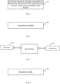
- the apparatus is applied to a network side device and includes: a transmission module 61, configured to transmit indication signaling on a target physical resource or a target downlink control channel, wherein the indication signaling includes monitoring information for at least one user equipment (UE), and the monitoring information includes at least one of:
- the target physical resource includes: a first orthogonal frequency division multiplexing (OFDM) symbol of a slot; and/or, an OFDM symbol where a control resource set (CORESET) for a downlink control channel is transmitted.
- OFDM orthogonal frequency division multiplexing
- CORESET control resource set
- the target downlink control channel includes: a control channel carrying common control information and/or a control channel carrying UE specific control information.
- the transmission module includes:
- the indication signaling is carried on the target physical resource or the target downlink control channel by means of a sequence.
- a frequency domain resource mapping unit of the target physical resource is: a resource element group (REG) of the downlink control channel; or, N resource blocks (RBs), wherein N is an integer greater than or equal to 1.
- REG resource element group
- RBs resource blocks
- a frequency domain resource position of the target physical resource is determined by predefinition or by network side signaling configuration; and/or, a time domain OFDM symbol position of the target physical resource is determined by predefinition or by network side signaling configuration.
- the activity state for the at least one subsequent DRX cycle indicated by the first indication information includes at least one of:
- the indication signaling includes the second indication information
- the third indication information indicates the monitoring information of the downlink control channel to be monitored through a value of at least one of following information:
- the type of the search space to be monitored includes: a common search space and/or a UE specific search space.
- a value of the search space set to be monitored includes: an index of a group of search space sets to be monitored, and/or, an index of the search space set to be monitored; wherein the group of search space sets to be monitored includes at least two search space sets to be monitored.
- a value of the candidate of the search space to be monitored includes at least one of: a ratio value of candidates of the search space to be monitored, an aggregation level of candidates of the search space to be monitored, and an identifier of an aggregation level group of candidates of the search space to be monitored; wherein the aggregation level group of the candidates of the search space to be monitored includes: at least two aggregation levels of the candidates of the search space to be monitored.
- the indication signaling is common indication signaling or UE specific indication signaling.
- the indication signaling is the common indication signaling
- monitoring information for different UE corresponds to different bits or a same bit in the indication signaling.
- the apparatus indicates dynamically monitoring information for UE on the target physical resource or the target downlink control channel, such that the UE may monitor the downlink control channel according to the corresponding monitoring information, to achieve the objective of power saving.
- the apparatus for transmitting indication signaling is an apparatus capable of implementing the foregoing method for transmitting indication signaling, and all embodiments of the method for transmitting indication signaling are applicable to the apparatus and may achieve the same or similar beneficial effects.
- an embodiment of the present disclosure further provides a network side device including a processor 700 and a transceiver 710.
- the processor 700 is configured to control the transceiver 710 to implement the following process: transmitting indication signaling on a target physical resource or a target downlink control channel, wherein the indication signaling includes monitoring information for at least one user equipment (UE), and the monitoring information includes at least one of:
- the target physical resource includes: a first orthogonal frequency division multiplexing (OFDM) symbol of a slot; and/or, an OFDM symbol where a control resource set (CORESET) for a downlink control channel is transmitted.
- OFDM orthogonal frequency division multiplexing
- CORESET control resource set
- the target downlink control channel includes: a control channel carrying common control information and/or a control channel carrying UE specific control information.
- the processor 700 is further configured to:
- the processor 700 is further configured to carry the indication signaling on the target physical resource or the target downlink control channel by means of a sequence.
- a frequency domain resource mapping unit of the target physical resource is: a resource element group (REG) of the downlink control channel; or, N resource blocks (RBs), wherein N is an integer greater than or equal to 1.
- REG resource element group
- RBs resource blocks
- a frequency domain resource position of the target physical resource is determined by predefinition or by network side signaling configuration; and/or, a time domain OFDM symbol position of the target physical resource is determined by predefinition or by network side signaling configuration.
- the activity state for the at least one subsequent DRX cycle indicated by the first indication information includes at least one of:
- the indication signaling includes the second indication information
- the third indication information indicates the monitoring information of the downlink control channel to be monitored through a value of at least one of following information:
- the type of the search space to be monitored includes: a common search space and/or a UE specific search space.
- a value of the search space set to be monitored includes: an index of a group of search space sets to be monitored, and/or, an index of the search space set to be monitored; wherein the group of search space sets to be monitored includes at least two search space sets to be monitored.
- a value of the candidate of the search space to be monitored includes at least one of: a ratio value of candidates of the search space to be monitored, an aggregation level of candidates of the search space to be monitored, and an identifier of an aggregation level group of candidates of the search space to be monitored; wherein the aggregation level group of the candidates of the search space to be monitored includes: at least two aggregation levels of the candidates of the search space to be monitored.
- the indication signaling is common indication signaling or UE specific indication signaling.
- the indication signaling is the common indication signaling
- monitoring information for different UE corresponds to different bits or a same bit in the indication signaling.
- the network side device indicates dynamically monitoring information for UE on the target physical resource or the target downlink control channel, such that the UE may monitor the downlink control channel according to the corresponding monitoring information, to achieve the objective of power saving.
- the network side device is a network side device capable of implementing the foregoing method for transmitting indication signaling, and all embodiments of the method for transmitting indication signaling are applicable to the network side device and may achieve the same or similar beneficial effects.
- An embodiment of the present disclosure further provides a computer readable storage medium storing therein a computer program, wherein the computer program is configured to be executed by a processor, to implement various processes of the embodiments of the foregoing method for transmitting indication signaling, and may achieve the same technical effects. To avoid repetition, a detailed description is omitted herein.
- the computer readable storage medium includes, for example, a read-only memory (ROM), random access memory (RAM), magnetic disk, optic disc, or the like.
- an embodiment of the present disclosure further provides an apparatus for receiving indication signaling.
- the apparatus is applied to UE and includes: a reception module 81, configured to receive indication signaling transmitted by a network side device on a target physical resource or a target downlink control channel, wherein the indication signaling includes monitoring information for at least one UE, and the monitoring information includes at least one of:
- the target physical resource includes: a first orthogonal frequency division multiplexing (OFDM) symbol of a slot; and/or, an OFDM symbol where a control resource set (CORESET) for a downlink control channel is transmitted.
- OFDM orthogonal frequency division multiplexing
- CORESET control resource set
- the target downlink control channel includes: a control channel carrying common control information and/or a control channel carrying UE specific control information.
- the reception module includes: a reception submodule, configured to receive encoded indication signaling transmitted by the network side device on the target physical resource or the target downlink control channel; wherein the indication signaling is encoded by the network side device in a manner where a mapping relationship between information bits and encoded bits exists; and/or, the indication signaling is encoded by the network side device in a channel encoding manner where an information bit is repeated or a code rate is low.
- the indication signaling is carried on the target physical resource or the target downlink control channel by means of a sequence.
- a frequency domain resource mapping unit of the target physical resource is: a resource element group (REG) of the downlink control channel; or, N resource blocks (RBs), wherein N is an integer greater than or equal to 1.
- REG resource element group
- RBs resource blocks
- a frequency domain resource position of the target physical resource is determined by predefinition or by network side signaling configuration; and/or, a time domain OFDM symbol position of the target physical resource is determined by predefinition or by network side signaling configuration.
- the activity state for the at least one subsequent DRX cycle indicated by the first indication information includes at least one of:
- the indication signaling includes the second indication information
- the third indication information indicates the monitoring information of the downlink control channel to be monitored through a value of at least one of following information:
- the type of the search space to be monitored includes: a common search space and/or a UE specific search space.
- a value of the search space set to be monitored includes: an index of a group of search space sets to be monitored, and/or, an index of the search space set to be monitored; wherein the group of search space sets to be monitored includes at least two search space sets to be monitored.
- a value of the candidate of the search space to be monitored includes at least one of: a ratio value of candidates of the search space to be monitored, an aggregation level of candidates of the search space to be monitored, and an identifier of an aggregation level group of candidates of the search space to be monitored; wherein the aggregation level group of the candidates of the search space to be monitored includes: at least two aggregation levels of the candidates of the search space to be monitored.
- the indication signaling is common indication signaling or UE specific indication signaling.
- the indication signaling is the common indication signaling
- monitoring information for different UE corresponds to different bits or a same bit in the indication signaling.
- the network side device indicates dynamically monitoring information for UE on the target physical resource or the target downlink control channel, such that the UE may monitor the downlink control channel according to the corresponding monitoring information, to achieve the objective of power saving.
- the apparatus for receiving indication signaling is an apparatus capable of implementing the foregoing method for receiving indication signaling, and all embodiments of the method for receiving indication signaling are applicable to the apparatus and may achieve the same or similar beneficial effects.
- an embodiment of the present disclosure further provides UE including a processor 900 and a transceiver 910.
- the UE further includes a user interface 920.
- the processor 900 is configured to control the transceiver 910 to implement the following process: receiving indication signaling transmitted by a network side device on a target physical resource or a target downlink control channel, wherein the indication signaling includes monitoring information for at least one UE, and the monitoring information includes at least one of:
- the target physical resource includes: a first orthogonal frequency division multiplexing (OFDM) symbol of a slot; and/or, an OFDM symbol where a control resource set (CORESET) for a downlink control channel is transmitted.
- OFDM orthogonal frequency division multiplexing
- CORESET control resource set
- the target downlink control channel includes: a control channel carrying common control information and/or a control channel carrying UE specific control information.
- the transceiver 900 is further configured to:
- the indication signaling is carried on the target physical resource or the target downlink control channel by means of a sequence.
- a frequency domain resource mapping unit of the target physical resource is: a resource element group (REG) of the downlink control channel; or, N resource blocks (RBs), wherein N is an integer greater than or equal to 1.
- REG resource element group
- RBs resource blocks
- a frequency domain resource position of the target physical resource is determined by predefinition or by network side signaling configuration; and/or, a time domain OFDM symbol position of the target physical resource is determined by predefinition or by network side signaling configuration.
- the activity state for the at least one subsequent DRX cycle indicated by the first indication information includes at least one of:
- the indication signaling includes the second indication information
- the third indication information indicates the monitoring information of the downlink control channel to be monitored through a value of at least one of following information:
- the type of the search space to be monitored includes: a common search space and/or a UE specific search space.
- a value of the search space set to be monitored includes: an index of a group of search space sets to be monitored, and/or, an index of the search space set to be monitored; wherein the group of search space sets to be monitored includes at least two search space sets to be monitored.
- a value of the candidate of the search space to be monitored includes at least one of: a ratio value of candidates of the search space to be monitored, an aggregation level of candidates of the search space to be monitored, and an identifier of an aggregation level group of candidates of the search space to be monitored; wherein the aggregation level group of the candidates of the search space to be monitored includes: at least two aggregation levels of the candidates of the search space to be monitored.
- the indication signaling is common indication signaling or UE specific indication signaling.
- the indication signaling is the common indication signaling
- monitoring information for different UE corresponds to different bits or a same bit in the indication signaling.
- the network side device indicates dynamically monitoring information for UE on the target physical resource or the target downlink control channel, such that the UE may monitor the downlink control channel according to the corresponding monitoring information, to achieve the objective of power saving.
- the UE according to the embodiment of the present disclosure is UE capable of implementing the foregoing method for receiving indication signaling, and all embodiments of the method for receiving indication signaling are applicable to the network side device and may achieve the same or similar beneficial effects.
- An embodiment of the present disclosure further provides a computer readable storage medium storing therein a computer program, wherein the computer program is configured to be executed by a processor, to implement various processes of the embodiments of the foregoing method for receiving indication signaling, and may achieve the same technical effects. To avoid repetition, a detailed description is omitted herein.
- the computer readable storage medium includes, for example, a read-only memory (ROM), random access memory (RAM), magnetic disk, optic disc or the like.
- embodiments of the present disclosure may be implemented as a method, system or computer program product. Therefore, embodiments of the present disclosure may take the form of a complete hardware embodiment, complete software embodiment or combination of hardware and software. Moreover, embodiments of the present disclosure may take the form of a computer program product embodied as one or more computer readable storage media (including, but not limited to, a magnetic disk storage, an optical storage or the like) storing therein computer usable program codes.
- These computer program instructions may also be stored in a computer-readable storage that can direct a computer or other programmable data processing device to function in a particular manner, such that the instructions stored in the computer-readable storage produce an article of manufacture including instruction means which implement the function specified in the flow diagram flow or flows and/or block diagram block or blocks.
- the computer program instructions may also be loaded onto a computer or other programmable data processing device to cause a series of operational steps to be performed on the computer or other programmable device to produce a computer-implemented process such that the instructions which are executed on the computer or other programmable device provide steps for implementing the functions specified in the flow diagram flow or flows and/or block diagram block or blocks.
Landscapes
- Engineering & Computer Science (AREA)
- Computer Networks & Wireless Communication (AREA)
- Signal Processing (AREA)
- Mobile Radio Communication Systems (AREA)
Claims (11)
- Procédé de transmission de signalisation d'indication, appliqué à un dispositif côté réseau, comprenant :
la transmission (21) d'une signalisation d'indication sur une ressource physique cible ou un canal de commande de liaison descendante, dans lequel la signalisation d'indication comprend au moins l'une des informations suivantes pour au moins un UE :des premières informations d'indication, utilisées pour indiquer un état d'activité pour au moins un cycle de réception discontinue, DRX, ultérieur ;des deuxièmes informations d'indication, utilisées pour indiquer une configuration de paramètre DRX pour l'au moins un cycle DRX ultérieur ;des troisièmes informations d'indication, utilisées pour indiquer un canal de commande de liaison descendante à surveiller ;caractérisé en ce que, dans un cas où la signalisation d'indication comprend les premières informations d'indication,l'état d'activité pour l'au moins un cycle DRX ultérieur indiqué par les premières informations d'indication comprend au moins l'un des éléments suivants :si un drx-onDurationTimer est démarré pour l'au moins un cycle DRX ultérieur à une position temporelle ;si un canal de commande de liaison descendante est surveillé pendant une période active pour l'au moins un cycle DRX ultérieur ;dans lequel la position temporelle comprend au moins l'un des éléments suivants :pour un drx-ShortCycle, une position temporelle après un décalage temporel représenté par un paramètre drx-SlotOffset à partir d'un début d'une sous-trame satisfaisant une première relation de contrainte ;pour un drx-LongCycle, une position temporelle après un décalage temporel représenté par un paramètre drx-SlotOffset à partir d'un début d'une sous-trame satisfaisant une seconde relation de contrainte ;dans lequel, dans un cas où la signalisation d'indication comprend les deuxièmes informations d'indication,dans un cas où une signalisation de couche supérieure configure une configuration de paramètre DRX, les deuxièmes informations d'indication indiquent un facteur d'échelle, et la configuration de paramètre DRX pour le cycle DRX est déterminée par la configuration de paramètre DRX configurée par la signalisation de couche supérieure et le facteur d'échelle ;dans lequel, dans un cas où la signalisation d'indication comprend les troisièmes informations d'indication, les troisièmes informations d'indication indiquent le canal de commande de liaison descendante à surveiller à travers au moins l'une des informations suivantes :un type d'un espace de recherche à surveiller ;un candidat de l'espace de recherche à surveiller ;un indice d'un groupe d'ensembles d'espaces de recherche à surveiller ;un indice de l'ensemble d'espaces de recherche à surveiller ;un type d'identifiant temporaire de réseau radio, RNTI, de l'espace de recherche à surveiller ;un format d'informations de commande de liaison descendante à surveiller ; etune longueur des informations de commande de liaison descendante à surveiller. - Procédé de réception de signalisation d'indication, appliqué à un équipement utilisateur, UE, comprenant :
la réception (51) d'une signalisation d'indication transmise par un dispositif côté réseau sur une ressource physique cible ou un canal de commande de liaison descendante, dans lequel la signalisation d'indication comprend au moins l'une des informations suivantes pour au moins un UE :des premières informations d'indication, utilisées pour indiquer un état d'activité pour au moins un cycle de réception discontinue, DRX, ultérieur ;des deuxièmes informations d'indication, utilisées pour indiquer une configuration de paramètre DRX pour l'au moins un cycle DRX ultérieur ;des troisièmes informations d'indication, utilisées pour indiquer un canal de commande de liaison descendante à surveiller ;caractérisé en ce que, dans un cas où la signalisation d'indication comprend les premières informations d'indication,l'état d'activité pour l'au moins un cycle DRX ultérieur indiqué par les premières informations d'indication comprend au moins l'un des éléments suivants :si un drx-onDurationTimer est démarré pour l'au moins un cycle DRX ultérieur à une position temporelle ;si un canal de commande de liaison descendante est surveillé pendant une période active pour l'au moins un cycle DRX ultérieur ;dans lequel la position temporelle comprend au moins l'un des éléments suivants :pour un drx-ShortCycle, une position temporelle après un décalage temporel représenté par un paramètre drx-SlotOffset à partir d'un début d'une sous-trame satisfaisant une première relation de contrainte ;pour un drx-LongCycle, une position temporelle après un décalage temporel représenté par un paramètre drx-SlotOffset à partir d'un début d'une sous-trame satisfaisant une seconde relation de contrainte ;dans lequel, dans un cas où la signalisation d'indication comprend les deuxièmes informations d'indication,dans un cas où une signalisation de couche supérieure configure une configuration de paramètre DRX, les deuxièmes informations d'indication indiquent un facteur d'échelle, et la configuration de paramètre DRX pour le cycle DRX est déterminée par la configuration de paramètre DRX configurée par la signalisation de couche supérieure et le facteur d'échelle ;dans lequel, dans un cas où la signalisation d'indication comprend les troisièmes informations d'indication, les troisièmes informations d'indication indiquent le canal de commande de liaison descendante à surveiller à travers au moins l'une des informations suivantes :un type d'un espace de recherche à surveiller ;un candidat de l'espace de recherche à surveiller ;un indice d'un groupe d'ensembles d'espaces de recherche à surveiller ;un indice de l'ensemble d'espaces de recherche à surveiller ;un type d'identifiant temporaire de réseau radio, RNTI, de l'espace de recherche à surveiller ;un format d'informations de commande de liaison descendante à surveiller ; etune longueur des informations de commande de liaison descendante à surveiller. - Procédé selon la revendication 2, dans lequel le canal de commande de liaison descendante comprend :
un canal de commande transportant des informations de commande communes et/ou un canal de commande transportant des informations de commande spécifiques à l'UE. - Procédé selon la revendication 2, dans lequel la réception de la signalisation d'indication transmise par le dispositif côté réseau sur la ressource physique cible ou le canal de commande de liaison descendante comprend :la réception d'une signalisation d'indication codée transmise par le dispositif côté réseau sur la ressource physique cible ou le canal de commande de liaison descendante ;dans lequel la signalisation d'indication est codée par le dispositif côté réseau d'une manière dans laquelle une relation de mappage entre des bits d'information et des bits codés existe ; et/ou, la signalisation d'indication est codée par le dispositif côté réseau d'une manière de codage de canal dans laquelle un bit d'information est répété ou un débit de code est faible.
- Procédé selon la revendication 2, dans lequel la signalisation d'indication est transportée sur la ressource physique cible ou le canal de commande de liaison descendante au moyen d'une séquence.
- Procédé selon la revendication 2, dans lequel le type de l'espace de recherche à surveiller comprend :
un espace de recherche commun et/ou un espace de recherche spécifique à l'UE. - Procédé selon la revendication 2, dans lequel le candidat de l'espace de recherche à surveiller comprend au moins l'un des éléments suivants : une valeur de ratio de candidats de l'espace de recherche à surveiller, un niveau d'agrégation de candidats de l'espace de recherche à surveiller, et un identifiant d'un groupe de niveaux d'agrégation de candidats de l'espace de recherche à surveiller : dans lequel le groupe de niveaux d'agrégation des candidats de l'espace de recherche à surveiller comporte : au moins deux niveaux d'agrégation des candidats de l'espace de recherche à surveiller.
- Procédé selon la revendication 2, dans lequel la signalisation d'indication est une signalisation d'indication commune ou une signalisation d'indication spécifique à l'UE.
- Procédé selon la revendication 8, dans lequel, dans un cas où la signalisation d'indication est la signalisation d'indication commune, différents UE correspondent à différents bits ou à un même bit dans la signalisation d'indication.
- Appareil de transmission de signalisation d'indication, appliqué à un dispositif côté réseau, comprenant :
un module de transmission (61), configuré pour transmettre une signalisation d'indication sur une ressource physique cible ou un canal de commande de liaison descendante, dans lequel la signalisation d'indication comprend au moins l'une des informations suivantes pour au moins un UE :des premières informations d'indication, utilisées pour indiquer un état d'activité pour au moins un cycle de réception discontinue, DRX, ultérieur ;des deuxièmes informations d'indication, utilisées pour indiquer une configuration de paramètre DRX pour l'au moins un cycle DRX ultérieur ;des troisièmes informations d'indication, utilisées pour indiquer un canal de commande de liaison descendante à surveiller ;caractérisé en ce que, dans un cas où la signalisation d'indication comprend les premières informations d'indication,l'état d'activité pour l'au moins un cycle DRX ultérieur indiqué par les premières informations d'indication comprend au moins l'un des éléments suivants :si un drx-onDurationTimer est démarré pour l'au moins un cycle DRX ultérieur à une position temporelle ;si un canal de commande de liaison descendante est surveillé pendant une période active pour l'au moins un cycle DRX ultérieur ;dans lequel la position temporelle comprend au moins l'un des éléments suivants :pour un drx-ShortCycle, une position temporelle après un décalage temporel représenté par un paramètre drx-SlotOffset à partir d'un début d'une sous-trame satisfaisant une première relation de contrainte ;pour un drx-LongCycle, une position temporelle après un décalage temporel représenté par un paramètre drx-SlotOffset à partir d'un début d'une sous-trame satisfaisant une seconde relation de contrainte ;dans lequel, dans un cas où la signalisation d'indication comprend les deuxièmes informations d'indication,dans un cas où une signalisation de couche supérieure configure une configuration de paramètre DRX, les deuxièmes informations d'indication indiquent un facteur d'échelle, et la configuration de paramètre DRX pour le cycle DRX est déterminée par la configuration de paramètre DRX configurée par la signalisation de couche supérieure et le facteur d'échelle ;dans lequel, dans un cas où la signalisation d'indication comprend les troisièmes informations d'indication, les troisièmes informations d'indication indiquent le canal de commande de liaison descendante à surveiller à travers au moins l'une des informations suivantes :un type d'un espace de recherche à surveiller ;un candidat de l'espace de recherche à surveiller ;un indice d'un groupe d'ensembles d'espaces de recherche à surveiller ;un indice de l'ensemble d'espaces de recherche à surveiller ;un type d'identifiant temporaire de réseau radio, RNTI, de l'espace de recherche à surveiller ;un format d'informations de commande de liaison descendante à surveiller ; etune longueur des informations de commande de liaison descendante à surveiller. - Appareil de réception de signalisation d'indication, appliqué à un équipement utilisateur, UE, comprenant :
un module de réception (81), configuré pour recevoir une signalisation d'indication transmise par un dispositif côté réseau sur une ressource physique cible ou un canal de commande de liaison descendante, dans lequel la signalisation d'indication comprend au moins l'une des informations suivantes pour au moins un UE :des premières informations d'indication, utilisées pour indiquer un état d'activité pour au moins un cycle de réception discontinue, DRX, ultérieur ;des deuxièmes informations d'indication, utilisées pour indiquer une configuration de paramètre DRX pour l'au moins un cycle DRX ultérieur ;des troisièmes informations d'indication, utilisées pour indiquer un canal de commande de liaison descendante à surveiller ;caractérisé en ce que, dans un cas où la signalisation d'indication comprend les premières informations d'indication,l'état d'activité pour l'au moins un cycle DRX ultérieur indiqué par les premières informations d'indication comprend au moins l'un des éléments suivants :si un drx-onDurationTimer est démarré pour l'au moins un cycle DRX ultérieur à une position temporelle ;si un canal de commande de liaison descendante est surveillé pendant une période active pour l'au moins un cycle DRX ultérieur ;dans lequel la position temporelle comprend au moins l'un des éléments suivants :pour un drx-ShortCycle, une position temporelle après un décalage temporel représenté par un paramètre drx-SlotOffset à partir d'un début d'une sous-trame satisfaisant une première relation de contrainte ;pour un drx-LongCycle, une position temporelle après un décalage temporel représenté par un paramètre drx-SlotOffset à partir d'un début d'une sous-trame satisfaisant une seconde relation de contrainte ;dans lequel, dans un cas où la signalisation d'indication comprend les deuxièmes informations d'indication,dans un cas où une signalisation de couche supérieure configure une configuration de paramètre DRX, les deuxièmes informations d'indication indiquent un facteur d'échelle, et la configuration de paramètre DRX pour le cycle DRX est déterminée par la configuration de paramètre DRX configurée par la signalisation de couche supérieure et le facteur d'échelle ;dans lequel, dans un cas où la signalisation d'indication comprend les troisièmes informations d'indication, les troisièmes informations d'indication indiquent le canal de commande de liaison descendante à surveiller à travers au moins l'une des informations suivantes :un type d'un espace de recherche à surveiller ;un candidat de l'espace de recherche à surveiller ;un indice d'un groupe d'ensembles d'espaces de recherche à surveiller ;un indice de l'ensemble d'espaces de recherche à surveiller ;un type d'identifiant temporaire de réseau radio, RNTI, de l'espace de recherche à surveiller ;un format d'informations de commande de liaison descendante à surveiller ; etune longueur des informations de commande de liaison descendante à surveiller.
Applications Claiming Priority (3)
| Application Number | Priority Date | Filing Date | Title |
|---|---|---|---|
| CN201811010219 | 2018-08-31 | ||
| CN201910023268.XA CN110876185B (zh) | 2018-08-31 | 2019-01-10 | 指示信令的传输、接收方法、装置、网络侧设备及终端 |
| PCT/CN2019/096082 WO2020042783A1 (fr) | 2018-08-31 | 2019-07-16 | Procédé et appareil de transmission et de réception de signalisation d'indication, dispositif côté réseau, et terminal |
Publications (3)
| Publication Number | Publication Date |
|---|---|
| EP3846549A1 EP3846549A1 (fr) | 2021-07-07 |
| EP3846549A4 EP3846549A4 (fr) | 2022-04-27 |
| EP3846549B1 true EP3846549B1 (fr) | 2024-10-09 |
Family
ID=69717077
Family Applications (1)
| Application Number | Title | Priority Date | Filing Date |
|---|---|---|---|
| EP19855225.9A Active EP3846549B1 (fr) | 2018-08-31 | 2019-07-16 | Procédé et appareil de transmission et de réception de signalisation d'indication |
Country Status (7)
| Country | Link |
|---|---|
| US (1) | US11711765B2 (fr) |
| EP (1) | EP3846549B1 (fr) |
| JP (1) | JP7206373B2 (fr) |
| CN (1) | CN110876185B (fr) |
| AU (1) | AU2019331959C1 (fr) |
| CA (1) | CA3110929C (fr) |
| SG (1) | SG11202102027QA (fr) |
Families Citing this family (33)
| Publication number | Priority date | Publication date | Assignee | Title |
|---|---|---|---|---|
| WO2021018531A1 (fr) * | 2019-08-01 | 2021-02-04 | Telefonaktiebolaget Lm Ericsson (Publ) | Critères de groupement d'équipement utilisateur (ue) et mécanismes de réduction de faux avertissement |
| US11665771B2 (en) | 2020-04-10 | 2023-05-30 | Qualcomm Incorporated | Wireless configuration of first and second zones with first and second sets of operating parameters |
| CN115428377B (zh) * | 2020-04-10 | 2024-06-14 | Oppo广东移动通信有限公司 | 信道资源的传输方法、装置、网络设备、终端和系统 |
| US12532260B2 (en) * | 2020-04-30 | 2026-01-20 | Qualcomm Incorporated | Wakeup signal selected cell indication |
| CN113596963B (zh) * | 2020-04-30 | 2024-02-02 | 华为技术有限公司 | 通信方法及装置 |
| CN113677008B (zh) | 2020-05-15 | 2025-09-02 | 华为技术有限公司 | 一种通信方法、装置及存储介质 |
| WO2022000267A1 (fr) * | 2020-06-30 | 2022-01-06 | Zte Corporation | Communications sans fil à consommation d'énergie réduite |
| CN114070460A (zh) * | 2020-08-06 | 2022-02-18 | 维沃移动通信有限公司 | 搜索空间集的配置方法、装置、终端及网络侧设备 |
| CN111934834B (zh) * | 2020-08-06 | 2024-12-24 | 中兴通讯股份有限公司 | 资源集合配置、检测方法、服务节点、终端及存储介质 |
| CN115315992A (zh) * | 2020-08-07 | 2022-11-08 | Oppo广东移动通信有限公司 | 一种寻呼指示方法、电子设备及存储介质 |
| CN114124293A (zh) * | 2020-08-31 | 2022-03-01 | 维沃移动通信有限公司 | 物理下行控制信道的监听方法、装置和设备 |
| EP4199604B1 (fr) | 2020-09-15 | 2025-05-07 | Guangdong Oppo Mobile Telecommunications Corp., Ltd. | Procédé d'économie d'énergie, dispositif terminal et dispositif réseau |
| US12531707B2 (en) * | 2020-10-23 | 2026-01-20 | Telefonaktiebolaget Lm Ericsson (Publ) | Physical downlink control channel limit handling for enhanced cross-carrier scheduling |
| CN114727390B (zh) * | 2021-01-04 | 2025-09-23 | 维沃移动通信有限公司 | 搜索空间组切换方法和设备 |
| US20240080767A1 (en) * | 2021-01-08 | 2024-03-07 | Lenovo (Beijing) Limited | Method and apparatus for monitoring physical downlink control channels |
| EP4266788A4 (fr) * | 2021-01-15 | 2024-02-28 | Huawei Technologies Co., Ltd. | Procédé de transmission de canal de commande de liaison descendante physique et appareil associé |
| CN117044326A (zh) * | 2021-01-15 | 2023-11-10 | 中兴通讯股份有限公司 | 用于物理下行控制信道pdcch监听的系统和方法 |
| CN114978445B (zh) * | 2021-02-27 | 2024-09-17 | 上海华为技术有限公司 | 一种数据传输方法及其设备 |
| CN115226187B (zh) * | 2021-04-20 | 2025-10-14 | 华为技术有限公司 | 一种非连续接收的配置方法及装置 |
| CN115515232B (zh) * | 2021-06-22 | 2026-04-10 | 维沃移动通信有限公司 | 间隙gap动态处理方法、终端及网络侧设备 |
| CN117397310A (zh) * | 2021-07-21 | 2024-01-12 | Oppo广东移动通信有限公司 | 一种drx配置方法及装置、终端设备、网络设备 |
| CN115706648A (zh) * | 2021-08-06 | 2023-02-17 | 大唐移动通信设备有限公司 | 控制信令监测方法、装置、设备及存储介质 |
| CN115884409B (zh) * | 2021-08-06 | 2025-12-09 | 大唐移动通信设备有限公司 | 动态数据传输方法、装置及存储介质 |
| CN113612595B (zh) * | 2021-09-07 | 2023-12-08 | 中信科移动通信技术股份有限公司 | 上行控制信息传输方法及装置 |
| WO2023176229A1 (fr) * | 2022-03-16 | 2023-09-21 | 日本電気株式会社 | Station de base, dispositif terminal, système de communication, procédé et support non transitoire lisible par ordinateur |
| US20230309182A1 (en) * | 2022-03-23 | 2023-09-28 | Qualcomm Incorporated | User equipment power saving algorithm for discontinuous reception scenarios |
| EP4512174A4 (fr) * | 2022-04-21 | 2026-03-11 | Zte Corp | Procédé de communication sans fil et dispositif associé |
| US20250331052A1 (en) * | 2022-05-27 | 2025-10-23 | Beijing Xiaomi Mobile Software Co., Ltd. | Method and apparatus for indicating tci state, and device and medium |
| EP4322695A1 (fr) * | 2022-08-12 | 2024-02-14 | Panasonic Intellectual Property Corporation of America | Équipement utilisateur et station de base |
| CN117880937A (zh) * | 2022-09-30 | 2024-04-12 | 大唐移动通信设备有限公司 | 资源位置的确定方法、设备、装置及存储介质 |
| CN118945900A (zh) * | 2023-05-12 | 2024-11-12 | 大唐移动通信设备有限公司 | 信息传输方法、装置、终端及网络设备 |
| CN120166493A (zh) * | 2023-12-15 | 2025-06-17 | 华为技术有限公司 | 信息传输方法和传输装置 |
| WO2025129466A1 (fr) * | 2023-12-19 | 2025-06-26 | Oppo广东移动通信有限公司 | Procédé et appareil d'instruction pour configuration de communication discontinue, et dispositif et support |
Family Cites Families (35)
| Publication number | Priority date | Publication date | Assignee | Title |
|---|---|---|---|---|
| US2647442A (en) * | 1945-12-18 | 1953-08-04 | Us Sec War | Gun shell feeding mechanism |
| US20030028441A1 (en) * | 2001-08-02 | 2003-02-06 | International Business Machines Corporation | Answer fulfillment-based marketing |
| CN101438511A (zh) * | 2006-03-24 | 2009-05-20 | 交互数字技术公司 | 用于保持上行链路同步并且降低电池功耗的方法和设备 |
| CN101155402A (zh) * | 2006-09-30 | 2008-04-02 | 北京三星通信技术研究有限公司 | 寻呼控制信道中传输澄清标识的设备和方法 |
| US20080159507A1 (en) * | 2006-12-27 | 2008-07-03 | Nokia Corporation | Distributed teleconference multichannel architecture, system, method, and computer program product |
| CN102172067B (zh) * | 2008-09-30 | 2016-02-03 | 爱立信电话股份有限公司 | 用于在电信系统中检测无线电链路故障的方法和设备 |
| CN101925161B (zh) | 2009-06-11 | 2014-11-19 | 株式会社Ntt都科摩 | 无线通信系统中自适应调整非连续接收模式的方法和装置 |
| CN102036178B (zh) * | 2009-09-29 | 2015-08-19 | 中兴通讯股份有限公司 | 一种发送、传输mbms通知指示信息的系统及方法 |
| CN102130711B (zh) | 2010-01-15 | 2015-01-28 | 中兴通讯股份有限公司 | 载波聚合系统中非连续接收活动时间的确定方法及装置 |
| CN102934382B (zh) * | 2010-06-04 | 2016-08-10 | Lg电子株式会社 | 控制探测参考信号发送的上行发送功率的方法和用户设备 |
| CN105722195B (zh) * | 2011-01-28 | 2019-12-24 | 华为技术有限公司 | 一种非连续接收的方法和装置 |
| CN102858014B (zh) * | 2011-06-30 | 2015-05-06 | 华为技术有限公司 | 控制信令的发送和接收方法及设备 |
| CN102932882B (zh) * | 2011-08-10 | 2018-05-11 | 中兴通讯股份有限公司 | 一种非连续接收方法及系统 |
| US9402264B2 (en) * | 2011-09-30 | 2016-07-26 | Intel Corporation | Methods to transport internet traffic over multiple wireless networks simultaneously |
| CN102595573A (zh) * | 2012-02-02 | 2012-07-18 | 电信科学技术研究院 | 一种配置drx参数的方法、系统和设备 |
| CN103391563B (zh) | 2012-05-11 | 2018-06-08 | 中兴通讯股份有限公司 | 下行控制信息发送方法、检测方法、基站及用户设备 |
| CN108462997B (zh) | 2012-08-02 | 2022-02-25 | 太阳专利信托公司 | 无线通信终端、基站装置、无线通信方法以及集成电路 |
| WO2014022962A1 (fr) * | 2012-08-06 | 2014-02-13 | 华为技术有限公司 | Procédé d'envoi de signalisation et dispositif apparenté |
| WO2014153698A1 (fr) * | 2013-03-25 | 2014-10-02 | 华为技术有限公司 | Procédé d'économie d'énergie, équipement utilisateur et station de base |
| CN104105199B (zh) * | 2013-04-02 | 2018-05-29 | 电信科学技术研究院 | 一种进行寻呼的方法、装置及系统 |
| CN104219738B (zh) * | 2013-05-29 | 2018-05-11 | 华为技术有限公司 | 非连续接收参数配置方法及装置 |
| CN104254112B (zh) * | 2013-06-29 | 2018-04-27 | 华为技术有限公司 | 网络通信方法、装置和系统 |
| JP6568058B2 (ja) * | 2014-05-30 | 2019-08-28 | シャープ株式会社 | 端末装置、基地局装置および通信方法 |
| CN107431982A (zh) | 2015-03-13 | 2017-12-01 | 华为技术有限公司 | 无线通信网络中的装置和方法 |
| US9504012B1 (en) * | 2015-05-22 | 2016-11-22 | Sony Corporation | Extended discontinuous reception mechanism |
| CN106604396A (zh) | 2015-10-16 | 2017-04-26 | 北京信威通信技术股份有限公司 | 一种触发上报信道状态指示的方法 |
| US20180077682A1 (en) | 2016-09-15 | 2018-03-15 | Huawei Technologies Co., Ltd. | Method and apparatus for application aware notifications in a wireless communication network |
| EP3556149B1 (fr) | 2016-12-14 | 2021-02-24 | Telefonaktiebolaget LM Ericsson (publ) | Construction de signal de réveil |
| CN110621068B (zh) | 2017-01-06 | 2020-11-20 | 华为技术有限公司 | 一种寻呼方法和装置 |
| EP4167619A1 (fr) * | 2017-02-02 | 2023-04-19 | IPLA Holdings Inc. | Nouvelle radiomessagerie radio |
| CN108513356B (zh) * | 2017-02-27 | 2020-01-07 | 维沃软件技术有限公司 | 一种资源分配指示方法、基站及终端 |
| US11115257B2 (en) * | 2017-03-23 | 2021-09-07 | Huawei Technologies Co., Ltd. | System and method for multiplexing traffic |
| EP3739996B1 (fr) * | 2018-01-11 | 2023-12-20 | Ntt Docomo, Inc. | Terminal d'utilisateur, et procédé de communication sans fil |
| MX2020007478A (es) * | 2018-01-12 | 2020-09-14 | Guangdong Oppo Mobile Telecommunications Corp Ltd | Metodo, dispositivo terminal y dispositivo de red para transmitir canales. |
| WO2019193688A1 (fr) * | 2018-04-04 | 2019-10-10 | 株式会社Nttドコモ | Terminal utilisateur et procédé de communication sans fil |
-
2019
- 2019-01-10 CN CN201910023268.XA patent/CN110876185B/zh active Active
- 2019-07-16 EP EP19855225.9A patent/EP3846549B1/fr active Active
- 2019-07-16 CA CA3110929A patent/CA3110929C/fr active Active
- 2019-07-16 US US17/271,770 patent/US11711765B2/en active Active
- 2019-07-16 AU AU2019331959A patent/AU2019331959C1/en active Active
- 2019-07-16 SG SG11202102027QA patent/SG11202102027QA/en unknown
- 2019-07-16 JP JP2021510810A patent/JP7206373B2/ja active Active
Also Published As
| Publication number | Publication date |
|---|---|
| JP2021536185A (ja) | 2021-12-23 |
| US11711765B2 (en) | 2023-07-25 |
| CA3110929A1 (fr) | 2020-03-05 |
| US20210337471A1 (en) | 2021-10-28 |
| EP3846549A4 (fr) | 2022-04-27 |
| AU2019331959B2 (en) | 2022-09-29 |
| SG11202102027QA (en) | 2021-03-30 |
| EP3846549A1 (fr) | 2021-07-07 |
| JP7206373B2 (ja) | 2023-01-17 |
| CN110876185A (zh) | 2020-03-10 |
| AU2019331959C1 (en) | 2023-04-06 |
| CN110876185B (zh) | 2021-07-09 |
| CA3110929C (fr) | 2023-09-26 |
| AU2019331959A1 (en) | 2021-05-06 |
Similar Documents
| Publication | Publication Date | Title |
|---|---|---|
| EP3846549B1 (fr) | Procédé et appareil de transmission et de réception de signalisation d'indication | |
| CN113287342B (zh) | 具有非连续接收配置的方法和装置 | |
| CN114642039B (zh) | 用于节省无线通信系统中用户设备的功率的方法及装置 | |
| CN114390655B (zh) | 无线通信中的节能方案 | |
| WO2020042783A1 (fr) | Procédé et appareil de transmission et de réception de signalisation d'indication, dispositif côté réseau, et terminal | |
| US10813077B2 (en) | Communications device, infrastructure equipment, communication system and methods for group paging and grouping communication devices based on various criteria | |
| CN113767681A (zh) | 用于下行链路控制信令的系统和方法 | |
| WO2009035280A2 (fr) | Procédés d'émission et de réception de données dans un système de transmission mobile | |
| CN116250369B (zh) | 一种通信方法及装置 | |
| CN115868218A (zh) | 在无线通信系统中执行寻呼的设备和方法 | |
| EP4568360A1 (fr) | Procédé, équipement utilisateur, dispositif de traitement, support de stockage, et programme informatique de réception de canal de liaison descendante, et procédé et station de base de transmission de canal de liaison descendante | |
| CN118450470A (zh) | 一种通信方法及装置 | |
| KR20210090549A (ko) | 페이징 메시지를 수신하는 방법 및 장치 | |
| EP3698585B1 (fr) | Équipement d'infrastructure, système de communication sans fil, dispositif et procédés de communication | |
| CN118749222A (zh) | 无线通信方法及其设备 | |
| EP4362370A1 (fr) | Procédé exécuté par un équipement utilisateur, et équipement utilisateur | |
| HK40047168B (en) | Method and apparatus for transmitting and receiving indication signaling | |
| HK40047168A (en) | Method and apparatus for transmitting and receiving indication signaling | |
| CA3143610C (fr) | Procede d'economie d'energie de terminal, appareil d'economie d'energie, procede et appareil d'envoi d'informations, support d'informations et dispositif electronique | |
| KR20250023304A (ko) | 저전력 웨이크업 수신기를 이용하여 무선 통신을 수행하는 방법 및 장치 | |
| KR20250007989A (ko) | 저전력 웨이크업 수신기를 이용하여 무선 통신을 수행하는 방법 및 장치 | |
| KR20250007430A (ko) | 저전력 웨이크업 수신기를 이용하여 무선 통신을 수행하는 방법 및 장치 | |
| KR20260025911A (ko) | 기지국 및 단말의 장치 및 방법 | |
| KR20260025910A (ko) | 기지국 및 단말의 장치 및 방법 | |
| KR20250009353A (ko) | 저전력 웨이크업 수신기를 이용하여 무선 통신을 수행하는 방법 및 장치 |
Legal Events
| Date | Code | Title | Description |
|---|---|---|---|
| STAA | Information on the status of an ep patent application or granted ep patent |
Free format text: STATUS: THE INTERNATIONAL PUBLICATION HAS BEEN MADE |
|
| STAA | Information on the status of an ep patent application or granted ep patent |
Free format text: STATUS: REQUEST FOR EXAMINATION WAS MADE |
|
| PUAI | Public reference made under article 153(3) epc to a published international application that has entered the european phase |
Free format text: ORIGINAL CODE: 0009012 |
|
| 17P | Request for examination filed |
Effective date: 20210330 |
|
| AK | Designated contracting states |
Kind code of ref document: A1 Designated state(s): AL AT BE BG CH CY CZ DE DK EE ES FI FR GB GR HR HU IE IS IT LI LT LU LV MC MK MT NL NO PL PT RO RS SE SI SK SM TR |
|
| REG | Reference to a national code |
Ref country code: HK Ref legal event code: DE Ref document number: 40047168 Country of ref document: HK |
|
| DAV | Request for validation of the european patent (deleted) | ||
| DAX | Request for extension of the european patent (deleted) | ||
| A4 | Supplementary search report drawn up and despatched |
Effective date: 20220325 |
|
| RIC1 | Information provided on ipc code assigned before grant |
Ipc: H04W 68/00 20090101ALN20220321BHEP Ipc: H04W 76/28 20180101ALI20220321BHEP Ipc: H04W 52/02 20090101AFI20220321BHEP |
|
| STAA | Information on the status of an ep patent application or granted ep patent |
Free format text: STATUS: EXAMINATION IS IN PROGRESS |
|
| 17Q | First examination report despatched |
Effective date: 20230712 |
|
| GRAP | Despatch of communication of intention to grant a patent |
Free format text: ORIGINAL CODE: EPIDOSNIGR1 |
|
| STAA | Information on the status of an ep patent application or granted ep patent |
Free format text: STATUS: GRANT OF PATENT IS INTENDED |
|
| RIC1 | Information provided on ipc code assigned before grant |
Ipc: H04W 68/00 20090101ALI20240627BHEP Ipc: H04W 76/28 20180101ALI20240627BHEP Ipc: H04W 52/02 20090101AFI20240627BHEP |
|
| INTG | Intention to grant announced |
Effective date: 20240725 |
|
| GRAS | Grant fee paid |
Free format text: ORIGINAL CODE: EPIDOSNIGR3 |
|
| GRAA | (expected) grant |
Free format text: ORIGINAL CODE: 0009210 |
|
| STAA | Information on the status of an ep patent application or granted ep patent |
Free format text: STATUS: THE PATENT HAS BEEN GRANTED |
|
| AK | Designated contracting states |
Kind code of ref document: B1 Designated state(s): AL AT BE BG CH CY CZ DE DK EE ES FI FR GB GR HR HU IE IS IT LI LT LU LV MC MK MT NL NO PL PT RO RS SE SI SK SM TR |
|
| REG | Reference to a national code |
Ref country code: CH Ref legal event code: EP |
|
| REG | Reference to a national code |
Ref country code: DE Ref legal event code: R096 Ref document number: 602019060248 Country of ref document: DE |
|
| REG | Reference to a national code |
Ref country code: IE Ref legal event code: FG4D |
|
| REG | Reference to a national code |
Ref country code: LT Ref legal event code: MG9D |
|
| REG | Reference to a national code |
Ref country code: DE Ref legal event code: R081 Ref document number: 602019060248 Country of ref document: DE Owner name: CHINA MOBILE COMMUNICATIONS GROUP CO., LTD., CN Free format text: FORMER OWNERS: CHINA MOBILE COMMUNICATION CO., LTD RESEARCH INSTITUTE, BEIJING, CN; CHINA MOBILE COMMUNICATIONS GROUP CO., LTD, BEIJING, CN Ref country code: DE Ref legal event code: R081 Ref document number: 602019060248 Country of ref document: DE Owner name: CHINA MOBILE COMMUNICATION CO., LTD RESEARCH I, CN Free format text: FORMER OWNERS: CHINA MOBILE COMMUNICATION CO., LTD RESEARCH INSTITUTE, BEIJING, CN; CHINA MOBILE COMMUNICATIONS GROUP CO., LTD, BEIJING, CN |
|
| REG | Reference to a national code |
Ref country code: NL Ref legal event code: MP Effective date: 20241009 |
|
| REG | Reference to a national code |
Ref country code: AT Ref legal event code: MK05 Ref document number: 1731986 Country of ref document: AT Kind code of ref document: T Effective date: 20241009 |
|
| PG25 | Lapsed in a contracting state [announced via postgrant information from national office to epo] |
Ref country code: NL Free format text: LAPSE BECAUSE OF FAILURE TO SUBMIT A TRANSLATION OF THE DESCRIPTION OR TO PAY THE FEE WITHIN THE PRESCRIBED TIME-LIMIT Effective date: 20241009 |
|
| PG25 | Lapsed in a contracting state [announced via postgrant information from national office to epo] |
Ref country code: NL Free format text: LAPSE BECAUSE OF FAILURE TO SUBMIT A TRANSLATION OF THE DESCRIPTION OR TO PAY THE FEE WITHIN THE PRESCRIBED TIME-LIMIT Effective date: 20241009 |
|
| PG25 | Lapsed in a contracting state [announced via postgrant information from national office to epo] |
Ref country code: HR Free format text: LAPSE BECAUSE OF FAILURE TO SUBMIT A TRANSLATION OF THE DESCRIPTION OR TO PAY THE FEE WITHIN THE PRESCRIBED TIME-LIMIT Effective date: 20241009 Ref country code: PT Free format text: LAPSE BECAUSE OF FAILURE TO SUBMIT A TRANSLATION OF THE DESCRIPTION OR TO PAY THE FEE WITHIN THE PRESCRIBED TIME-LIMIT Effective date: 20250210 Ref country code: IS Free format text: LAPSE BECAUSE OF FAILURE TO SUBMIT A TRANSLATION OF THE DESCRIPTION OR TO PAY THE FEE WITHIN THE PRESCRIBED TIME-LIMIT Effective date: 20250209 |
|
| PG25 | Lapsed in a contracting state [announced via postgrant information from national office to epo] |
Ref country code: FI Free format text: LAPSE BECAUSE OF FAILURE TO SUBMIT A TRANSLATION OF THE DESCRIPTION OR TO PAY THE FEE WITHIN THE PRESCRIBED TIME-LIMIT Effective date: 20241009 |
|
| PG25 | Lapsed in a contracting state [announced via postgrant information from national office to epo] |
Ref country code: BG Free format text: LAPSE BECAUSE OF FAILURE TO SUBMIT A TRANSLATION OF THE DESCRIPTION OR TO PAY THE FEE WITHIN THE PRESCRIBED TIME-LIMIT Effective date: 20241009 |
|
| PG25 | Lapsed in a contracting state [announced via postgrant information from national office to epo] |
Ref country code: ES Free format text: LAPSE BECAUSE OF FAILURE TO SUBMIT A TRANSLATION OF THE DESCRIPTION OR TO PAY THE FEE WITHIN THE PRESCRIBED TIME-LIMIT Effective date: 20241009 |
|
| PG25 | Lapsed in a contracting state [announced via postgrant information from national office to epo] |
Ref country code: NO Free format text: LAPSE BECAUSE OF FAILURE TO SUBMIT A TRANSLATION OF THE DESCRIPTION OR TO PAY THE FEE WITHIN THE PRESCRIBED TIME-LIMIT Effective date: 20250109 |
|
| PG25 | Lapsed in a contracting state [announced via postgrant information from national office to epo] |
Ref country code: LV Free format text: LAPSE BECAUSE OF FAILURE TO SUBMIT A TRANSLATION OF THE DESCRIPTION OR TO PAY THE FEE WITHIN THE PRESCRIBED TIME-LIMIT Effective date: 20241009 Ref country code: GR Free format text: LAPSE BECAUSE OF FAILURE TO SUBMIT A TRANSLATION OF THE DESCRIPTION OR TO PAY THE FEE WITHIN THE PRESCRIBED TIME-LIMIT Effective date: 20250110 Ref country code: AT Free format text: LAPSE BECAUSE OF FAILURE TO SUBMIT A TRANSLATION OF THE DESCRIPTION OR TO PAY THE FEE WITHIN THE PRESCRIBED TIME-LIMIT Effective date: 20241009 |
|
| PG25 | Lapsed in a contracting state [announced via postgrant information from national office to epo] |
Ref country code: PL Free format text: LAPSE BECAUSE OF FAILURE TO SUBMIT A TRANSLATION OF THE DESCRIPTION OR TO PAY THE FEE WITHIN THE PRESCRIBED TIME-LIMIT Effective date: 20241009 |
|
| PG25 | Lapsed in a contracting state [announced via postgrant information from national office to epo] |
Ref country code: RS Free format text: LAPSE BECAUSE OF FAILURE TO SUBMIT A TRANSLATION OF THE DESCRIPTION OR TO PAY THE FEE WITHIN THE PRESCRIBED TIME-LIMIT Effective date: 20250109 |
|
| PG25 | Lapsed in a contracting state [announced via postgrant information from national office to epo] |
Ref country code: SM Free format text: LAPSE BECAUSE OF FAILURE TO SUBMIT A TRANSLATION OF THE DESCRIPTION OR TO PAY THE FEE WITHIN THE PRESCRIBED TIME-LIMIT Effective date: 20241009 |
|
| PG25 | Lapsed in a contracting state [announced via postgrant information from national office to epo] |
Ref country code: DK Free format text: LAPSE BECAUSE OF FAILURE TO SUBMIT A TRANSLATION OF THE DESCRIPTION OR TO PAY THE FEE WITHIN THE PRESCRIBED TIME-LIMIT Effective date: 20241009 |
|
| PGFP | Annual fee paid to national office [announced via postgrant information from national office to epo] |
Ref country code: GB Payment date: 20250529 Year of fee payment: 7 |
|
| REG | Reference to a national code |
Ref country code: DE Ref legal event code: R097 Ref document number: 602019060248 Country of ref document: DE |
|
| PG25 | Lapsed in a contracting state [announced via postgrant information from national office to epo] |
Ref country code: EE Free format text: LAPSE BECAUSE OF FAILURE TO SUBMIT A TRANSLATION OF THE DESCRIPTION OR TO PAY THE FEE WITHIN THE PRESCRIBED TIME-LIMIT Effective date: 20241009 |
|
| PG25 | Lapsed in a contracting state [announced via postgrant information from national office to epo] |
Ref country code: RO Free format text: LAPSE BECAUSE OF FAILURE TO SUBMIT A TRANSLATION OF THE DESCRIPTION OR TO PAY THE FEE WITHIN THE PRESCRIBED TIME-LIMIT Effective date: 20241009 |
|
| PG25 | Lapsed in a contracting state [announced via postgrant information from national office to epo] |
Ref country code: SK Free format text: LAPSE BECAUSE OF FAILURE TO SUBMIT A TRANSLATION OF THE DESCRIPTION OR TO PAY THE FEE WITHIN THE PRESCRIBED TIME-LIMIT Effective date: 20241009 |
|
| PG25 | Lapsed in a contracting state [announced via postgrant information from national office to epo] |
Ref country code: CZ Free format text: LAPSE BECAUSE OF FAILURE TO SUBMIT A TRANSLATION OF THE DESCRIPTION OR TO PAY THE FEE WITHIN THE PRESCRIBED TIME-LIMIT Effective date: 20241009 |
|
| PG25 | Lapsed in a contracting state [announced via postgrant information from national office to epo] |
Ref country code: IT Free format text: LAPSE BECAUSE OF FAILURE TO SUBMIT A TRANSLATION OF THE DESCRIPTION OR TO PAY THE FEE WITHIN THE PRESCRIBED TIME-LIMIT Effective date: 20241009 |
|
| PLBE | No opposition filed within time limit |
Free format text: ORIGINAL CODE: 0009261 |
|
| STAA | Information on the status of an ep patent application or granted ep patent |
Free format text: STATUS: NO OPPOSITION FILED WITHIN TIME LIMIT |
|
| PG25 | Lapsed in a contracting state [announced via postgrant information from national office to epo] |
Ref country code: SE Free format text: LAPSE BECAUSE OF FAILURE TO SUBMIT A TRANSLATION OF THE DESCRIPTION OR TO PAY THE FEE WITHIN THE PRESCRIBED TIME-LIMIT Effective date: 20241009 |
|
| 26N | No opposition filed |
Effective date: 20250710 |
|
| PGFP | Annual fee paid to national office [announced via postgrant information from national office to epo] |
Ref country code: DE Payment date: 20250724 Year of fee payment: 7 |
|
| PGFP | Annual fee paid to national office [announced via postgrant information from national office to epo] |
Ref country code: FR Payment date: 20250722 Year of fee payment: 7 |
|
| REG | Reference to a national code |
Ref country code: CH Ref legal event code: H13 Free format text: ST27 STATUS EVENT CODE: U-0-0-H10-H13 (AS PROVIDED BY THE NATIONAL OFFICE) Effective date: 20260224 |
|
| PG25 | Lapsed in a contracting state [announced via postgrant information from national office to epo] |
Ref country code: LU Free format text: LAPSE BECAUSE OF NON-PAYMENT OF DUE FEES Effective date: 20250716 |
|
| REG | Reference to a national code |
Ref country code: BE Ref legal event code: MM Effective date: 20250731 |
|
| PG25 | Lapsed in a contracting state [announced via postgrant information from national office to epo] |
Ref country code: BE Free format text: LAPSE BECAUSE OF NON-PAYMENT OF DUE FEES Effective date: 20250731 |
|
| PG25 | Lapsed in a contracting state [announced via postgrant information from national office to epo] |
Ref country code: CH Free format text: LAPSE BECAUSE OF NON-PAYMENT OF DUE FEES Effective date: 20250731 |