EP3846697B1 - Medizinisches instrument zum gerichteten einbringen einer therapeutischen substanz in einen hohlraum und werkzeug dafür - Google Patents
Medizinisches instrument zum gerichteten einbringen einer therapeutischen substanz in einen hohlraum und werkzeug dafür Download PDFInfo
- Publication number
- EP3846697B1 EP3846697B1 EP19787159.3A EP19787159A EP3846697B1 EP 3846697 B1 EP3846697 B1 EP 3846697B1 EP 19787159 A EP19787159 A EP 19787159A EP 3846697 B1 EP3846697 B1 EP 3846697B1
- Authority
- EP
- European Patent Office
- Prior art keywords
- tool
- fluid line
- medical instrument
- shaft
- fluid
- Prior art date
- Legal status (The legal status is an assumption and is not a legal conclusion. Google has not performed a legal analysis and makes no representation as to the accuracy of the status listed.)
- Active
Links
Images

Classifications
-
- A—HUMAN NECESSITIES
- A61—MEDICAL OR VETERINARY SCIENCE; HYGIENE
- A61B—DIAGNOSIS; SURGERY; IDENTIFICATION
- A61B17/00—Surgical instruments, devices or methods
- A61B17/00234—Surgical instruments, devices or methods for minimally invasive surgery
-
- A—HUMAN NECESSITIES
- A61—MEDICAL OR VETERINARY SCIENCE; HYGIENE
- A61B—DIAGNOSIS; SURGERY; IDENTIFICATION
- A61B17/00—Surgical instruments, devices or methods
- A61B17/34—Trocars; Puncturing needles
-
- A—HUMAN NECESSITIES
- A61—MEDICAL OR VETERINARY SCIENCE; HYGIENE
- A61B—DIAGNOSIS; SURGERY; IDENTIFICATION
- A61B17/00—Surgical instruments, devices or methods
- A61B17/34—Trocars; Puncturing needles
- A61B17/3474—Insufflating needles, e.g. Veress needles
-
- A—HUMAN NECESSITIES
- A61—MEDICAL OR VETERINARY SCIENCE; HYGIENE
- A61M—DEVICES FOR INTRODUCING MEDIA INTO, OR ONTO, THE BODY; DEVICES FOR TRANSDUCING BODY MEDIA OR FOR TAKING MEDIA FROM THE BODY; DEVICES FOR PRODUCING OR ENDING SLEEP OR STUPOR
- A61M11/00—Sprayers or atomisers specially adapted for therapeutic purposes
- A61M11/006—Sprayers or atomisers specially adapted for therapeutic purposes operated by applying mechanical pressure to the liquid to be sprayed or atomised
-
- A—HUMAN NECESSITIES
- A61—MEDICAL OR VETERINARY SCIENCE; HYGIENE
- A61M—DEVICES FOR INTRODUCING MEDIA INTO, OR ONTO, THE BODY; DEVICES FOR TRANSDUCING BODY MEDIA OR FOR TAKING MEDIA FROM THE BODY; DEVICES FOR PRODUCING OR ENDING SLEEP OR STUPOR
- A61M13/00—Insufflators for therapeutic or disinfectant purposes, i.e. devices for blowing a gas, powder or vapour into the body
-
- B—PERFORMING OPERATIONS; TRANSPORTING
- B05—SPRAYING OR ATOMISING IN GENERAL; APPLYING FLUENT MATERIALS TO SURFACES, IN GENERAL
- B05B—SPRAYING APPARATUS; ATOMISING APPARATUS; NOZZLES
- B05B15/00—Details of spraying plant or spraying apparatus not otherwise provided for; Accessories
- B05B15/14—Arrangements for preventing or controlling structural damage to spraying apparatus or its outlets, e.g. for breaking at desired places; Arrangements for handling or replacing damaged parts
- B05B15/16—Arrangements for preventing or controlling structural damage to spraying apparatus or its outlets, e.g. for breaking at desired places; Arrangements for handling or replacing damaged parts for preventing non-intended contact between spray heads or nozzles and foreign bodies, e.g. nozzle guards
-
- B—PERFORMING OPERATIONS; TRANSPORTING
- B05—SPRAYING OR ATOMISING IN GENERAL; APPLYING FLUENT MATERIALS TO SURFACES, IN GENERAL
- B05B—SPRAYING APPARATUS; ATOMISING APPARATUS; NOZZLES
- B05B15/00—Details of spraying plant or spraying apparatus not otherwise provided for; Accessories
- B05B15/60—Arrangements for mounting, supporting or holding spraying apparatus
- B05B15/65—Mounting arrangements for fluid connection of the spraying apparatus or its outlets to flow conduits
-
- A—HUMAN NECESSITIES
- A61—MEDICAL OR VETERINARY SCIENCE; HYGIENE
- A61M—DEVICES FOR INTRODUCING MEDIA INTO, OR ONTO, THE BODY; DEVICES FOR TRANSDUCING BODY MEDIA OR FOR TAKING MEDIA FROM THE BODY; DEVICES FOR PRODUCING OR ENDING SLEEP OR STUPOR
- A61M2202/00—Special media to be introduced, removed or treated
- A61M2202/04—Liquids
- A61M2202/0468—Liquids non-physiological
-
- A—HUMAN NECESSITIES
- A61—MEDICAL OR VETERINARY SCIENCE; HYGIENE
- A61M—DEVICES FOR INTRODUCING MEDIA INTO, OR ONTO, THE BODY; DEVICES FOR TRANSDUCING BODY MEDIA OR FOR TAKING MEDIA FROM THE BODY; DEVICES FOR PRODUCING OR ENDING SLEEP OR STUPOR
- A61M2205/00—General characteristics of the apparatus
- A61M2205/02—General characteristics of the apparatus characterised by a particular materials
- A61M2205/0216—Materials providing elastic properties, e.g. for facilitating deformation and avoid breaking
Definitions
- the invention relates to a medical instrument for the directed introduction of a therapeutic substance into a cavity of a body.
- EP 3 354 213 A1 such an instrument as an applicator, which has a trocar sleeve in which a needle is guided.
- a needle nozzle is detachably attached to the distal end of the needle, through whose openings a substance is introduced into the body cavity.
- a tube connects a substance source to the trocar sleeve.
- a first embodiment of the medical instrument is designed for the directed introduction of a therapeutic substance into a cavity of a body.
- the medical instrument has a trocar, a fluid source, a fluid pump and a tool that can be fluidically connected to the fluid source and the fluid pump and can be introduced into a body cavity via the trocar.
- the tool has a shaft with a lumen and further has a flexible fluid line and a nozzle head, wherein the flexible fluid line extends in the lumen of the shaft and the nozzle head is connected to the flexible fluid line.
- the proximal end of the flexible fluid line can be connected directly to the fluid source, so that the tool is connected to the fluid source and the fluid pump via the flexible fluid line.
- the fluid source can accommodate a predetermined substance, e.g. a medication, a gas or a combination of both, or can include other components that are necessary to introduce the substance into the body cavity.
- a body cavity can be any cavity in the body, and can also be understood as a surgically created cavity, such as an artificially created pneumoperitoneum.
- a simple tool as a component is used to create a very simply constructed and reliable medical instrument, in which only one connection point is required for the fluidic transfer of the therapeutic substance to the nozzle head, namely between the flexible fluid line of the tool and the fluid source with fluid pump.
- This avoids further connection points, in particular between a fluid supply line or a transition piece fluidically connected to the fluid source and the tool, which according to the state of the art is usually located at the proximal end of the tool, which corresponds to the proximal end of the shaft.
- the fluid can be a liquid or a gas or a A combination thereof may be used, wherein the fluid carries or comprises the therapeutic substance and can be sprayed with the nozzle head.
- the flexible fluid line of the medical instrument extends at least over the entire length of the shaft, but preferably also flexibly beyond it, so that the flexible fluid line can be connected directly to a fluid source in which the therapeutic substance is provided.
- the flexible fluid line is therefore connected directly to the fluid source; no additional fluid line is required to carry the therapeutic substance from the source to the shaft, and therefore no additional connection or connecting pieces are required.
- the flexible fluid line can also extend beyond the distal end of the shaft.
- the nozzle head is arranged at a distal end of the tool. It can extend partially or completely into the lumen of the shaft and is thus already stably positioned.
- the nozzle head is preferably connected to the flexible fluid line via a connector.
- the nozzle head can also be connected directly to the flexible fluid line.
- the connection can be designed to be non-detachable or also as a detachable connection via a screw or bayonet connection or another type of connection.
- a further embodiment of the medical instrument according to the invention provides that the shaft is made of a plastic, whereby the shaft can be guided over the flexible fluid line as a prefabricated tube to produce an assembly arrangement or, conversely, the fluid line can be guided into the shaft.
- the shaft can also be injection-molded from the plastic around the flexible fluid line and is thus adapted to the flexible fluid line. During injection-molded processing, other components can be attached at the same time or fastening elements can be provided.
- the shape, size and path of the flexible fluid line do not have to be taken into account when manufacturing the shaft, nor does it have to contain any positioning means for the flexible fluid line. No additional Connections between an external fluid line coming from the fluid source and the tool shaft are no longer necessary; instead, the flexible fluid line is led directly into the shaft, through the shaft to the nozzle itself.
- the plastic design not only makes the medical instrument inexpensive to manufacture, but it can also serve as a disposable tool that can be thrown away after one use. Because it consists of few components, it is also recyclable and easy to dispose of.
- the flexible fluid line and the connector can be detachably connected to one another.
- the connection can be made using a thread between the two components or by simply plugging them in.
- the flexible fluid line and the connector can be loose before assembly and placed butt-to-butt to create an assembly arrangement, and then glued together or overmolded with plastic.
- the flexible fluid line and the connector i.e. both components, are permanently connected to one another.
- the connection between the two components can be realized, for example, by gluing or welding.
- the shaft and the connector can have locking elements that correspond to one another so that the locking elements can engage with one another in an assembly arrangement.
- both components can have threads that correspond to one another so that the connector and shaft can be screwed together.
- the medical instrument can have a protective cap at its distal end, which surrounds the nozzle body.
- the same as for the connection between the connector and the shaft can be implemented for the protective cap, so that it cannot simply be pushed on, but can be held firmly on the shaft.
- the protective cap can be locked to the shaft by means of suitable locking elements, the corresponding locking elements.
- the protective cap can be glued, welded or sprayed onto the shaft.
- the flexible fluid line has a lumen in which the fluid can flow.
- the nozzle is designed to generate an aerosol and comprises a nozzle body that can be connected to the connector.
- both components can be detachably connected to one another, preferably screwed.
- the connector can have a thread, preferably an internal thread, for which the nozzle body can have a corresponding counter thread, preferably an external thread.
- the connector also has a lumen that is followed in the flow direction by a through hole that is narrower than the first lumen.
- the through hole is adjacent to a central hole in the nozzle body and opens into a centering cone in the flow direction, which applies the fluid to the nozzle hole.
- this is thin in order to apply pressure to the fluid and give it a correspondingly high flow rate.
- the fluid can then flow out of a nozzle opening that is located on the front side (distal end of the tool) of the nozzle body. All of the aforementioned lumens are in fluid communication in order to guide the therapeutic substance to the nozzle opening where it is to be sprayed.
- the flexible fluid line has a connector designed to detachably connect the fluid line and thus the tool to the fluid source in order to be able to fluidically connect the lumen of the tool to a fluid source and a fluid pump.
- a connector designed to detachably connect the fluid line and thus the tool to the fluid source in order to be able to fluidically connect the lumen of the tool to a fluid source and a fluid pump.
- This is preferably a medically approved standard connector, particularly preferably a Luer-Lock connector.
- the medical instrument according to the invention makes it possible to provide a very simply constructed means for minimally invasive surgery.
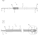
- the tool 1 shows a shaft 2 which terminates at a distal end 1b of the tool 1 with a protective cap 4.
- a grooved handle 5 is formed on the shaft 2.
- a flexible fluid line 3 extends from the proximal end 1a, which is connected to further components in order to form a medical instrument 20, as in Fig.4
- the shaft 2 is essentially made of a solid plastic and serves to stabilize the flexible fluid line 3.
- the medical instrument 20 according to the invention in Fig.4 is designed to interact with a body cavity 21.
- a trocar 22 is inserted into the body cavity 21.
- the tool 1 can interact with this trocar 22; that is, can be inserted into it.
- the medical instrument 20 also has a fluid source 23 that is connected to a fluid pump 24.
- the fluid source 23 is detachably connected to the flexible fluid line 3 and thus directly to the tool 1 via a connection 25, which can in particular be a Luer-Lock connection.
- Fig. 2 is a cut A - A by tool 1 to Fig.1 shown.
- a section B - in detail in Fig.3 shown - shows an end section 2a of the tool 1 from Fig.2 .
- the flexible fluid line 3 has, as shown in the longitudinal section in Fig. 2 shown, a lumen 6 through which the fluid can flow.
- the flexible fluid line 3 lies with an elongated section within the shaft 2, which has a lumen 7 to house the flexible fluid line 3, wherein the flexible fluid line 3 extends proximally beyond the end of the shaft 2 out of the shaft 2.
- the flexible fluid line 3 is guided through the lumen 7 to the distal end section 2a, in which a connecting piece 14 is present in the lumen 7 of the shaft 2.
- This connecting piece 14 is cylindrical and has a lumen 13, the inner diameter of which essentially corresponds to the outer diameter of the flexible fluid line 3.
- the connecting piece 14 and the fluid line 3 are in Fig. 2 inserted into each other.
- a through-opening or bore 15 is provided in the connecting piece 14, which is fluidically connected to the lumen 6 of the fluid line 3, as well as a thread 11, which adjoins the through-bore 15, widens the diameter again and extends in the direction of the distal end 1b of the tool 1.
- a nozzle body 10, which is surrounded by the protective cap 4, is screwed into the thread 11.
- the nozzle body 10 has a thread corresponding to the thread 11, so that the nozzle body 10 can be screwed into the connecting piece 14 and replaced if necessary.
- the nozzle body 10 has a central bore 16, which opens into a centering cone 17 and finally extends into a nozzle bore 9. This nozzle bore 9 is followed by a nozzle opening 8, which is located on the front side of the tool 1, i.e. the distal end 1b of the tool 1.
- a direct supply of the fluid to the nozzle body 10 is realized via the flexible fluid line 3; it is not necessary to transfer the fluid from one fluid-carrying component to the next, but the fluid line 3 provides the complete fluid guidance from the fluid source 23 to the nozzle body 10.
- the connection via the connecting piece 14 is optional; alternatively, the nozzle body 10 can be connected directly, without a connecting piece, detachably or non-detachably, to the flexible fluid line 3.
- the protective cap 4 is held within the shaft 2 by means of locking elements 12. These locking elements 12 can be formed both on the outside of the protective cap 4 and on the inside of the lumen 7 of the shaft 2.
Landscapes
- Health & Medical Sciences (AREA)
- Life Sciences & Earth Sciences (AREA)
- Surgery (AREA)
- Engineering & Computer Science (AREA)
- Public Health (AREA)
- Veterinary Medicine (AREA)
- Heart & Thoracic Surgery (AREA)
- Biomedical Technology (AREA)
- Animal Behavior & Ethology (AREA)
- General Health & Medical Sciences (AREA)
- Nuclear Medicine, Radiotherapy & Molecular Imaging (AREA)
- Medical Informatics (AREA)
- Molecular Biology (AREA)
- Anesthesiology (AREA)
- Hematology (AREA)
- Pathology (AREA)
- Mechanical Engineering (AREA)
- Surgical Instruments (AREA)
- Infusion, Injection, And Reservoir Apparatuses (AREA)
- Media Introduction/Drainage Providing Device (AREA)
Description
- Die Erfindung betrifft ein medizinisches Instrument zum gerichteten Einbringen einer therapeutischen Substanz in einen Hohlraum eines Körpers.
- Aus dem Stand der Technik sind medizinische Instrumente zum gerichteten Einbringen einer Substanz in einen Hohlraum eines Körpers bekannt, die in der minimal-invasiven Chirurgie eingesetzt werden. Aus der
DE 10 2012 104 629 A1 ist ein solches Instrument bekannt, wobei ein dafür passendes Werkzeug einen Schaft aufweist, an dessen distalem Ende eine Düse angeordnet ist, mit der eine therapeutische Substanz in einem Pneumoperitoneum versprüht werden kann. Die wesentlichen Bestandteile des Werkzeugs sind aus Metall, um es desinfizieren zu können. Zudem weist es einen komplexen inneren Aufbau auf. - Ferner beschreibt
EP 3 354 213 A1 ein solches Instrument als Applikator, der eine Trokarhülse aufweist, in der eine Nadel geführt ist. Am distalen Ende der Nadel ist eine Nadeldüse lösbar angebracht, durch deren Öffnungen eine Substanz in den Körperhohlraum eingebracht wird. Ein Schlauch verbindet eine Substanzquelle mit der Trokarhülse. -
DE 295 16 077 U1 schlägt eine Sprühvorrichtung für Zwei-Komponenten-Kleber vor, wobei zwei Rohre innerhalb eines steifen Rohrteils verlaufen und distal in einen auf das Rohrteil aufschraubbaren Düsenkopf münden, in dem die Komponenten vor dem Versprühen vermischt werden. Zur separierten Zufuhr der Komponenten sind Rohrstücke am proximalen Ende des Rohrteils zur Verbindung mit einer Doppelspritze angeordnet. Das DokumentUS2011/213296 A1 offenbart ein medizinisches Instrument zum Einbringen einer therapeutischen Substanz in einen Hohlraum des Körpers aus dem Stand der Technik. - Ausgehend von diesem Stand der Technik ist es Aufgabe der vorliegenden Erfindung, ein möglichst einfach aufgebautes und kostengünstig herzustellendes medizinisches Instrument zum gerichteten Einbringen einer Substanz in einen Hohlraum eines Körpers ausgebildet ist, bereitzustellen.
- Diese Aufgabe wird durch ein medizinisches Instrument mit den Merkmalen des Anspruchs 1 gelöst.
- Bevorzugte Ausführungsformen des medizinischen Instruments sind in den Unteransprüchen ausgeführt.
- Eine erste Ausführungsform des medizinischen Instruments ist ausgebildet zum gerichteten Einbringen einer therapeutischen Substanz in einen Hohlraum eines Körpers. Das medizinische Instrument weist einen Trokar, eine Fluidquelle, eine Fluidpumpe sowie ein Werkzeug auf, das mit der Fluidquelle und der Fluidpumpe fluidisch verbunden werden kann und über den Trokar in eine Körperhöhle eingeführt werden kann. Das Werkzeug hat einen Schaft mit einem Lumen und weist ferner eine flexible Fluidleitung und einen Düsenkopf auf, wobei die flexible Fluidleitung sich in dem Lumen des Schafts erstreckt und der Düsenkopf mit der flexiblen Fluidleitung verbunden ist. Das proximale Ende der flexiblen Fluidleitung kann mit der Fluidquelle direkt verbunden werden, so dass das Werkzeug mit der Fluidquelle und der Fluidpumpe über die flexible Fluidleitung verbunden ist.
- So kann ein geeigneter Fluidstrom von Fluidquelle bis zur Verteilung des Fluids in der Körperhöhle erzeugt werden. Die Fluidquelle kann eine vorbestimmte Substanz, bspw. ein Medikament, ferner ein Gas oder eine Kombination aus beidem beherbergen bzw. noch weitere Komponenten umfassen, die notwendig sind, um die Substanz in die Körperhöhle einzubringen. Eine Körperhöhle kann jeder körpereigene Hohlraum sein, und auch als chirurgisch erzeugter Hohlraum, wie ein künstlich angelegtes Pneumoperitoneum, verstanden werden.
- Vorteilhaft wird so mit einem einfachen Werkzeug als Bauteil ein sehr einfach aufgebautes und zuverlässiges medizinisches Instrument geschaffen, bei dem zur fluidischen Überführung der therapeutischen Substanz zum Düsenkopf nur eine Verbindungsstelle, nämlich zwischen der flexiblen Fluidleitung des Werkzeugs und der Fluidquelle mit Fluidpumpe, nötig ist. Somit werden weitere Verbindungsstellen vermieden, insbesondere zwischen einer an die Fluidquelle fluidisch angeschlossenen Fluidzuführleitung bzw. einem Übergangsstück und dem Werkzeug, die gemäß Stand der Technik üblicherweise an dem proximalen Ende des Werkzeugs vorliegt, das dem proximalen Ende des Schafts entspricht. Dadurch liegen weniger Fehlerquellen vor, die beispielsweise Undichtheit und damit Druckverlust in der Leitung bedeuten könnten. Sofern damit weniger Verwendungsmöglichkeiten und ggf. schlechtere Reinigbarkeit des Werkzeugs und damit des medizinischen Instruments einhergehen, ist dies unproblematisch, da das Werkzeug kostengünstig auch als Einmalprodukt verwendbar ist. Die Herstellung des medizinischen Instruments ist zudem kostengünstig. Als Fluid kann eine Flüssigkeit oder ein Gas oder eine Kombination daraus verwendet werden, wobei das Fluid die therapeutische Substanz trägt oder umfasst und mit dem Düsenkopf versprüht werden kann.
- Die flexible Fluidleitung des medizinischen Instruments erstreckt sich dabei zumindest über die gesamte Länge des Schafts, bevorzugt aber auch flexibel darüber hinaus, sodass die flexible Fluidleitung direkt mit einer Fluidquelle, in der die therapeutische Substanz vorgelegt ist, verbunden werden kann. Es wird daher ein direkter Anschluss der flexiblen Fluidleitung an die Fluidquelle vorgenommen, es ist keine zusätzliche Fluidleitung, die die therapeutische Substanz von der Quelle zu dem Schaft führt, nötig, und damit auch kein zusätzlicher Anschluss bzw. Verbindungsstücke.
- Auch über das distale Ende des Schafts hinaus kann sich die flexible Fluidleitung erstrecken.
- In noch einer weiteren Ausführungsform des erfindungsgemäßen medizinischen Instruments ist der Düsenkopf an einem distalen Ende des Werkzeugs angeordnet. Er kann sich teilweise oder vollständig in das Lumen des Schafts erstrecken und wird dadurch bereits stabil positioniert. Bevorzugt ist der Düsenkopf mit der flexiblen Fluidleitung über ein Verbindungsstück verbunden. Alternativ kann der Düsenkopf mit der flexiblen Fluidleitung auch direkt verbunden sein. Die Verbindung kann unlösbar gestaltet sein oder auch als lösbare Verbindung über eine Schraub- oder Bajonettverbindung oder eine andere Verbindungsart ausgebildet sein. Vorteilhaft ist es dadurch nicht zwingend nötig, den Düsenkopf mit dem Schaft zu verbinden, sodass der Schaft sehr einfach gefertigt werden kann.
- Eine weitere Ausführungsform des erfindungsgemäßen medizinischen Instruments sieht vor, dass der Schaft aus einem Kunststoff besteht, wobei der Schaft zur Herstellung einer Montageanordnung als vorgefertigtes Rohr über die flexible Fluidleitung geführt werden kann bzw. auch umgekehrt die Fluidleitung in den Schaft geführt werden kann. Alternativ kann der Schaft auch aus dem Kunststoff um die flexible Fluidleitung gespritzt werden und ist damit angepasst an die flexible Fluidleitung. Beim Aufspritzen können zugleich andere Komponenten befestigt werden oder Befestigungselemente vorgesehen werden.
- Damit wird eine kostengünstige Herstellung ermöglicht. Bei der Schaftfertigung müssen Form, Größe und Verlauf der flexiblen Fluidleitung nicht berücksichtigt werden, er muss auch keine Positioniermittel für die flexible Fluidleitung enthalten. Es sind keine zusätzlichen Anschlüsse zwischen einer extern von der Fluidquelle kommenden Fluidleitung und Werkzeug-Schaft mehr notwendig, sondern die flexible Fluidleitung ist direkt in den Schaft hinein, durch den Schaft hindurch bis zur Düse selbst geführt.
- Die Ausführung aus Kunststoff macht das medizinische Instrument nicht nur kostengünstig in der Herstellung, sondern es kann auch als Einmal-Werkzeug dienen, dass nach einmaligem Gebrauch weggeworfen werden kann. Dadurch, dass es aus wenigen Bestandteilen besteht, ist es auch recycelbar bzw. einfach zu entsorgen.
- Ferner können die flexible Fluidleitung und das Verbindungsstück lösbar miteinander verbunden sein. Je nach Ausgestaltung kann die Verbindung über ein Gewinde zwischen beiden Komponenten oder mittels einfachem Stecken realisiert sein. Alternativ können die flexible Fluidleitung und das Verbindungsstück vor Montage aber auch lose vorliegen und zur Herstellung einer Montageanordnung Stoß an Stoß gelegt werden, um dann miteinander verklebt oder mit Kunststoff umspritzt zu werden.
- In noch einer weiteren Ausführungsform des erfindungsgemäßen medizinischen Instruments sind die flexible Fluidleitung und das Verbindungsstück, also beide Komponenten miteinander, unlösbar miteinander verbunden. Je nach Ausgestaltung kann die Verbindung zwischen beiden Komponenten beispielsweise mittels Verkleben oder Verschwei-βen realisiert sein.
- Um die Komponenten Verbindungsstück und Schaft miteinander zu verbinden, sodass der Düsenkörper, der fest in dem Verbindungsstück aufgenommen ist, fest gefasst werden kann, können der Schaft und das Verbindungsstück zueinander korrespondierende Rastelemente aufweisen, sodass in einer Montageanordnung die Rastelemente im Eingriff zueinander stehen können. Für eine gute Prozesssicherheit können beide Komponenten zueinander korrespondierende Gewinde aufweisen, sodass Verbindungsstück und Schaft miteinander verschraubt werden können.
- Ferner kann das medizinische Instrument an seinem distalen Ende eine Schutzkappe aufweisen, die den Düsenkörper umgibt. Das Gleiche wie für die Verbindung Verbindungsstück und Schaft kann für die Schutzkappe realisiert sein, damit diese nicht einfach aufgesteckt, sondern fest am Schaft gehalten werden kann. Die Schutzkappe kann mittels geeigneter Rastelemente mit dem Schaft verrastet werden, der dazu korrespondierende Rastelemente aufweist. Ferner kann die Schutzkappe mit dem Schaft verklebt, verschweißt oder aufgespritzt werden.
- Damit das Fluid, das die therapeutische Substanz trägt oder umfasst, auch mittels des Düsenkopfes versprüht werden kann, weist die flexible Fluidleitung ein Lumen auf, in dem das Fluid strömen kann. Die Düse ist ausgebildet zur Erzeugung eines Aerosols und umfasst einen Düsenkörper, der mit dem Verbindungsstück verbunden werden kann. Dazu können in einer weiteren Ausführungsform des medizinischen Instruments beide Komponenten miteinander lösbar verbunden, bevorzugt verschraubt sein. Dazu kann das Verbindungsstück ein Gewinde, bevorzugt ein Innengewinde, aufweisen, wozu der Düsenkörper ein entsprechend korrespondierendes Gegengewinde, bevorzugt ein Außengewinde, aufweisen kann. Das Verbindungsstück hat ferner ein Lumen, das in Strömungsrichtung von einer Durchtrittsbohrung gefolgt wird, die enger als das erste Lumen ist. Die Durchtrittsbohrung liegt in der Montageanordnung benachbart zu einer mittigen Bohrung des Düsenkörpers an und mündet in Strömungsrichtung in einen Zentrierkonus, der das Fluid auf die Düsenbohrung beaufschlagt. Diese ist im Vergleich zu den vorgenannten Lumina dünn ausgebildet, um das Fluid mit Druck zu beaufschlagen und ihm eine entsprechend hohe Strömungsgeschwindigkeit zu verleihen. Aus einer Düsenöffnung, die an der Stirnseite (distales Ende des Werkzeugs) des Düsenkörpers angeordnet ist, kann dann das Fluid ausströmen. Alle genannten Lumina stehen in fluidischer Verbindung, um die therapeutische Substanz zur Düsenöffnung zu führen, die dort versprüht werden soll.
- In noch einer weiteren Ausführungsform des medizinischen Instruments weist die flexible Fluidleitung, um das Lumen des Werkzeugs mit einer Fluidquelle und einer Fluidpumpe fluidisch verbinden zu können, einen Anschluss auf, der dazu ausgebildet ist, die Fluidleitung und somit das Werkzeug lösbar mit der Fluidquelle zu verbinden. Bevorzugt handelt es sich um einen medizinisch zugelassenen Standard-Anschluss, besonders bevorzugt um einen Luer-Lock-Anschluss.
- Das erfindungsgemäße medizinische Instrument erlaubt, ein sehr einfach aufgebautes Mittel für die minimal-invasive Chirurgie bereitzustellen.
- Weitere Ausführungsformen des medizinischen Instruments sowie einige der Vorteile, die mit diesen und weiteren Ausführungsformen verbunden sind, werden durch die nachfolgende ausführliche Beschreibung unter Bezug auf die begleitenden Figuren deutlich und besser verständlich. Die Figuren sind lediglich eine schematische Darstellung einer Ausführungsform der Erfindung.
- Dabei zeigen:
- Fig. 1
- eine schematische Ansicht des Werkzeugs,
- Fig. 2
- einen Längsschnitt nach Schnitt A-A durch das Werkzeug,
- Fig. 3
- eine Detailansicht B eines distalen Endabschnitts des Werkzeugs, und
- Fig. 4
- eine schematische Ansicht des erfindungsgemäßen medizinischen Instruments.
- In
Fig. 1 zeigt das Werkzeug 1 einen Schaft 2, der an einem distalen Ende 1b des Werkzeugs 1 mit einer Schutzkappe 4 abschließt. In einem Abschnitt, der sich an ein proximales Ende 1a des Werkzeugs 1 anschließt, ist ein geriffelter Griff 5 an den Schaft 2 ausgebildet. Aus dem proximalen Ende 1a erstreckt sich eine flexible Fluidleitung 3, die mit weiteren Komponenten verbunden ist, um ein medizinisches Instrument 20, wie inFig. 4 dargestellt, zu schaffen. Der Schaft 2 ist im Wesentlichen aus einem festen Kunststoff gefertigt, und dient der Stabilisierung der flexiblen Fluidleitung 3. - Das erfindungsgemäße medizinische Instrument 20 in
Fig. 4 ist dazu ausgebildet, mit einer Körperhöhle 21 zusammen zu wirken. Dazu ist in die Körperhöhle 21 ein Trokar 22 eingeführt. Das Werkzeug 1 kann mit diesem Trokar 22 wechselwirken; also in diesen eingeführt werden. Ferner weist das medizinische Instrument 20 eine Fluidquelle 23 auf, die mit einer Fluidpumpe 24 verbunden ist. Über einen Anschluss 25, der insbesondere ein Luer-Lock-Anschluss sein kann, ist die Fluidquelle 23 mit der flexiblen Fluidleitung 3 und damit direkt mit dem Werkzeug 1 lösbar verbunden. - In
Fig. 2 ist ein Schnitt A - A durch das Werkzeug 1 nachFig. 1 gezeigt. Ein Ausschnitt B - im Detail inFig. 3 gezeigt - zeigt einen Endabschnitt 2a des Werkzeugs 1 ausFig. 2 . Die flexible Fluidleitung 3 hat, wie in dem Längsschnitt inFig. 2 gezeigt, ein Lumen 6, durch das das Fluid strömen kann. Die flexible Fluidleitung 3 liegt dabei mit einem länglichen Abschnitt innerhalb des Schafts 2, der dazu ein Lumen 7 aufweist, um eben die flexible Fluidleitung 3 zu hausen, wobei sich die flexible Fluidleitung 3 proximal über das Ende des Schafts 2 hinaus aus dem Schaft 2 heraus erstreckt. - Die flexible Fluidleitung 3 ist durch das Lumen 7 bis zu dem distalen Endabschnitt 2a geführt, in dem ein Verbindungsstück 14 in dem Lumen 7 des Schafts 2 vorliegt. Dieses Verbindungsstück 14 ist zylindrisch und weist ein Lumen 13 auf, dessen Innendurchmesser im Wesentlichen dem Außendurchmesser der flexiblen Fluidleitung 3 entspricht. Verbindungsstück 14 und Fluidleitung 3 sind in
Fig. 2 ineinander gesteckt. - Ferner ist in dem Verbindungsstück 14 eine Durchtrittsöffnung bzw. -Bohrung 15 vorgesehen, die mit dem Lumen 6 der Fluidleitung 3 fluidisch in Verbindung steht, sowie ein Gewinde 11, das sich an die Durchtrittsbohrung 15 anschließt, diese im Durchmesser wieder erweitert und sich in Richtung des distalen Endes 1b des Werkzeugs 1 erstreckt. In das Gewinde 11 eingeschraubt ist ein Düsenkörper 10, der von der Schutzkappe 4 umgeben wird. Der Düsenkörper 10 weist ein zu dem Gewinde 11 korrespondierendes Gewinde auf, sodass der Düsenkörper 10 in das Verbindungsstück 14 eingeschraubt und bei Bedarf ausgetauscht werden kann. Der Düsenkörper 10 weist eine mittige Bohrung 16 auf, die in einen Zentrierkonus 17 mündet und sich schließlich in eine Düsenbohrung 9 erstreckt. An diese Düsenbohrung 9 schließt sich eine Düsenöffnung 8 an, die an der Stirnseite des Werkzeugs 1, also dem distalen Ende 1b des Werkzeugs 1 vorliegt.
- Somit wird eine direkte Zuleitung des Fluids zum Düsenkörper 10 über die flexible Fluidleitung 3 realisiert; es ist nicht nötig, das Fluid von einer Fluid führenden Komponente in die nächste zu überführen, sondern die Fluidleitung 3 stellt die komplette Fluidführung von der Fluidquelle 23 bis zum Düsenkörper 10 bereit. Die Verbindung über das Verbindungsstück 14 ist dabei optional; alternativ kann der Düsenkörper 10 direkt, ohne Verbindungsstück, lösbar oder unlösbar, mit der flexiblen Fluidleitung 3 verbunden sein.
- Die Schutzkappe 4 wird innerhalb des Schafts 2 mittels Rastelementen 12 gehalten. Diese Rastelemente 12 können sowohl an der Außenseite der Schutzkappe 4 sowie an der Innenseite des Lumens 7 des Schafts 2 ausgebildet sein.
-
- 1
- Werkzeug
- 1a
- Proximales Ende
- 1b
- Distales Ende
- 2
- Schaft
- 2a
- Distaler Endabschnitt
- 3
- Flexible Fluidleitung
- 4
- Schutzkappe
- 5
- Griff
- 6
- Lumen Fluidleitung
- 7
- Lumen Schaft
- 8
- Düsenöffnung
- 9
- Düsenbohrung
- 10
- Düsenkörper
- 11
- Gewinde
- 12
- Rastelemente
- 13
- Lumen Verbindungsstück
- 14
- Verbindungsstück
- 15
- Durchtrittsbohrung
- 16
- Mittige Bohrung
- 17
- Zentrierkonus
- 20
- Medizinisches Instrument
- 21
- Körperhöhle
- 22
- Trokar
- 23
- Fluidquelle
- 24
- Fluidpumpe
- 25
- Anschluss
Claims (7)
- Medizinisches Instrument (20) zum Einbringen einer therapeutischen Substanz in eine Körperhöhle (21), mit einem Trokar (22), einer Fluidquelle (23), einer Fluidpumpe (24) sowie einem Werkzeug (1), das mit der Fluidquelle (23) und der Fluidpumpe (24) fluidisch verbindbar ist und über den Trokar (22) in eine Körperhöhle (21) einführbar ist, wobei das Werkzeug (1) einen starren Schaft (2) mit einem Lumen (7) aufweist und eine flexible Fluidleitung (3) und einen Düsenkopf (10) aufweist, wobei die flexible Fluidleitung (3) sich in dem Lumen (7) des starren Schafts (2) erstreckt und der Düsenkopf (10) mit der flexiblen Fluidleitung (3) verbunden ist, wobei das proximale Ende der flexiblen Fluidleitung (3) mit der Fluidquelle (23) direkt verbindbar ist, und die Verbindung des Werkzeugs (1) mit der Fluidquelle (23) und der Fluidpumpe (24) bereitstellt, und wobei der Düsenkopf (10) des Werkzeugs (1) an einem distalen Ende (1 b) des Werkzeugs (1) angeordnet ist und sich teilweise oder vollständig in das Lumen (7) des starren Schafts (2) erstreckt; und der Düsenkopf (10) mit der flexiblen Fluidleitung (3) direkt oder über ein Verbindungsstück (14) verbunden ist.
- Medizinisches Instrument (20) nach Anspruch 1,
dadurch gekennzeichnet, dass
der Schaft (2) aus einem Kunststoff besteht, wobei der Schaft (2) zur Herstellung einer Montageanordnung als vorgefertigtes Rohr über die flexible Fluidleitung (3) führbar ist oder aus dem Kunststoff um die flexible Fluidleitung (3) spritzbar ist. - Medizinisches Instrument (20) nach zumindest einem der Ansprüche 1 bis 2,
dadurch gekennzeichnet, dass
die flexible Fluidleitung (3) und das Verbindungsstück (14) unlösbar miteinander verbunden sind. - Medizinisches Instrument (20) nach zumindest einem der Ansprüche 1 bis 3,
dadurch gekennzeichnet, dass
der Schaft (2) und das Verbindungsstück (14) zueinander korrespondierende Rastelemente (12) aufweisen, so dass in einer Montageanordnung die Rastelemente (12) im Eingriff zueinander sind. - Medizinisches Instrument (20) nach zumindest einem der Ansprüche 1 bis 4,
dadurch gekennzeichnet, dass
das Werkzeug (1) an seinem distalen Ende (1a) eine Schutzkappe (4) aufweist, die den Düsenkörper (10) umgibt. - Medizinisches Instrument (20) nach zumindest einem der Ansprüche 1 bis 5,
dadurch gekennzeichnet, dass
die flexible Fluidleitung (3) ein Lumen (6) aufweist, in dem das Fluid strömbar ist. - Medizinisches Instrument (20) nach zumindest einem der Ansprüche 1 bis 6,
dadurch gekennzeichnet, dass
die flexible Fluidleitung (3) zur fluidischen Verbindung des Lumens (6) mit einer Fluidquelle (23) und der Fluidpumpe (24) einen Anschluss (25) aufweist, wobei der Anschluss (25) ein Luer-Lock-Anschluss ist.
Priority Applications (1)
| Application Number | Priority Date | Filing Date | Title |
|---|---|---|---|
| EP24191827.5A EP4477156A1 (de) | 2018-09-04 | 2019-09-04 | Medizinisches instrument zum gerichteten einbringen einer therapeutischen substanz in einen hohlraum und werkzeug dafür |
Applications Claiming Priority (2)
| Application Number | Priority Date | Filing Date | Title |
|---|---|---|---|
| DE102018121496.0A DE102018121496A1 (de) | 2018-09-04 | 2018-09-04 | Medizinisches Instrument zum gerichteten Einbringen einer therapeutischen Substanz in einen Hohlraum und Werkzeug dafür |
| PCT/EP2019/000254 WO2020048627A1 (de) | 2018-09-04 | 2019-09-04 | Medizinisches instrument zum gerichteten einbringen einer therapeutischen substanz in einen hohlraum und werkzeug dafür |
Related Child Applications (1)
| Application Number | Title | Priority Date | Filing Date |
|---|---|---|---|
| EP24191827.5A Division EP4477156A1 (de) | 2018-09-04 | 2019-09-04 | Medizinisches instrument zum gerichteten einbringen einer therapeutischen substanz in einen hohlraum und werkzeug dafür |
Publications (2)
| Publication Number | Publication Date |
|---|---|
| EP3846697A1 EP3846697A1 (de) | 2021-07-14 |
| EP3846697B1 true EP3846697B1 (de) | 2024-07-31 |
Family
ID=68242625
Family Applications (2)
| Application Number | Title | Priority Date | Filing Date |
|---|---|---|---|
| EP24191827.5A Pending EP4477156A1 (de) | 2018-09-04 | 2019-09-04 | Medizinisches instrument zum gerichteten einbringen einer therapeutischen substanz in einen hohlraum und werkzeug dafür |
| EP19787159.3A Active EP3846697B1 (de) | 2018-09-04 | 2019-09-04 | Medizinisches instrument zum gerichteten einbringen einer therapeutischen substanz in einen hohlraum und werkzeug dafür |
Family Applications Before (1)
| Application Number | Title | Priority Date | Filing Date |
|---|---|---|---|
| EP24191827.5A Pending EP4477156A1 (de) | 2018-09-04 | 2019-09-04 | Medizinisches instrument zum gerichteten einbringen einer therapeutischen substanz in einen hohlraum und werkzeug dafür |
Country Status (3)
| Country | Link |
|---|---|
| EP (2) | EP4477156A1 (de) |
| DE (2) | DE102018121496A1 (de) |
| WO (1) | WO2020048627A1 (de) |
Families Citing this family (3)
| Publication number | Priority date | Publication date | Assignee | Title |
|---|---|---|---|---|
| CZ34539U1 (cs) * | 2020-09-24 | 2020-11-16 | SKALA-Medica s.r.o. | Miniinvazinní chirurgická tryska, zejména pro potřeby invazivní chirurgie |
| DE102022104560A1 (de) | 2022-02-25 | 2023-08-31 | Capnopharm UG (haftungsbeschränkt) | Medizinisches Instrument zum Einbringen einer fluidförmigen therapeutischen Substanz in einen Hohlraum eines Körpers |
| DE102022131155A1 (de) * | 2022-11-24 | 2024-05-29 | Reger Medizintechnik Gmbh | Medizinisches instrument zum multidirektionalen verdüsen eines fluids in einen hohlraum eines körpers und werkzeug dafür |
Citations (2)
| Publication number | Priority date | Publication date | Assignee | Title |
|---|---|---|---|---|
| US20110213296A1 (en) * | 2010-02-26 | 2011-09-01 | Amit Agarwal | Blower Instrument, Apparatus and Methods of Using |
| EP2695626A1 (de) * | 2012-08-10 | 2014-02-12 | Nordson Corporation | Vorrichtung zum Entladen einer reaktiven Flüssigkeit |
Family Cites Families (5)
| Publication number | Priority date | Publication date | Assignee | Title |
|---|---|---|---|---|
| DE29516077U1 (de) * | 1995-10-10 | 1997-02-06 | Maslanka, Harald, 78532 Tuttlingen | Sprühvorrichtung |
| WO2000006216A1 (en) * | 1998-07-27 | 2000-02-10 | Focal, Inc. | Universal modular surgical applicator systems |
| DE202011101151U1 (de) | 2011-05-27 | 2011-07-26 | Alexander Hetzel | Mikropumpe zur Herstellung eines therapeutischen Pneumoperitoneums |
| JP5779467B2 (ja) * | 2011-09-30 | 2015-09-16 | 住友ベークライト株式会社 | 生体組織接着剤塗布用具およびノズルヘッド |
| EP3354213B1 (de) * | 2017-01-25 | 2021-05-05 | Silke König | Applikator zum einbringen einer substanz in eine körperhöhle |
-
2018
- 2018-09-04 DE DE102018121496.0A patent/DE102018121496A1/de active Pending
-
2019
- 2019-09-04 DE DE202019005985.7U patent/DE202019005985U1/de active Active
- 2019-09-04 WO PCT/EP2019/000254 patent/WO2020048627A1/de not_active Ceased
- 2019-09-04 EP EP24191827.5A patent/EP4477156A1/de active Pending
- 2019-09-04 EP EP19787159.3A patent/EP3846697B1/de active Active
Patent Citations (2)
| Publication number | Priority date | Publication date | Assignee | Title |
|---|---|---|---|---|
| US20110213296A1 (en) * | 2010-02-26 | 2011-09-01 | Amit Agarwal | Blower Instrument, Apparatus and Methods of Using |
| EP2695626A1 (de) * | 2012-08-10 | 2014-02-12 | Nordson Corporation | Vorrichtung zum Entladen einer reaktiven Flüssigkeit |
Also Published As
| Publication number | Publication date |
|---|---|
| WO2020048627A1 (de) | 2020-03-12 |
| EP4477156A1 (de) | 2024-12-18 |
| EP3846697A1 (de) | 2021-07-14 |
| DE202019005985U1 (de) | 2023-11-16 |
| DE102018121496A1 (de) | 2020-03-05 |
Similar Documents
| Publication | Publication Date | Title |
|---|---|---|
| EP0454816B1 (de) | Injektionsvorrichtung | |
| EP0315222A2 (de) | Vorrichtung zur Applikation eines Gewebeklebstoffes | |
| EP1269925B1 (de) | Zugangskanüle für endoskopische Operationen, insbesondere für die Arthroskopie | |
| EP3145417A1 (de) | Laparoskopischer sprayapplikator und adapter | |
| EP2953557A1 (de) | Trokar | |
| EP4477156A1 (de) | Medizinisches instrument zum gerichteten einbringen einer therapeutischen substanz in einen hohlraum und werkzeug dafür | |
| EP1740106A1 (de) | Applikator für die wasserstrahl-chirurgie | |
| EP2377562B1 (de) | Spülsystem zur Reinigung von Operationswunden | |
| EP3638353A1 (de) | Medizinisches punktionsinstrument | |
| DE29516077U1 (de) | Sprühvorrichtung | |
| EP1303219B1 (de) | Medizinisches instrument, insbesondere resektoskop | |
| DE29509729U1 (de) | Adapterhülse und Katheter-Set mit einer solchen Adapterhülse | |
| DE102013222525B4 (de) | Ventileinrichtung für wenigstens einen Saug- und/oder Spülkanal eines chirurgischen Instruments | |
| EP1350478B1 (de) | Kanüle zum Applizieren von medizinischen Stoffen | |
| EP3845209B1 (de) | Phaco-emulsifikationshandstück | |
| EP4622693B1 (de) | Medizinisches instrument zum multidirektionalen verdüsen eines fluids in einen hohlraum eines körpers und werkzeug dafür | |
| DE102018121513B4 (de) | Medizinisches Instrument zum gerichteten Einbringen einer Substanz in einen Hohlraum eines Körpers und Werkzeug dafür | |
| EP3064158B1 (de) | Medizinische Vorrichtung mit Wasserstrahlapplikator und Verfahren zur Aufrüstung einer chirurgischen Schere | |
| EP3117786A1 (de) | Instrument zum entfernen von körpergewebe aus einem fistelgang | |
| DE4025503A1 (de) | Injektionsvorrichtung | |
| EP1755440A1 (de) | Vorrichtung zum aufweiten von organ- oder körperöffnungen | |
| DE102023114208A1 (de) | Einrichtung zur axialen Lagefixierung eines Instruments in einem Führungselement bei einer endoskopischen Behandlungsvorrichtung | |
| DE102022005028A1 (de) | Albarran und Zugdrahtmitnehmer für einen Albarran | |
| DE102015122650A1 (de) | Injektionseinrichtung für eine endoskopische Vorrichtung, sowie endoskopische Vorrichtung | |
| DE20110491U1 (de) | Zugangskanüle für endoskopische Operationen, insbesondere für die Arthroskopie |
Legal Events
| Date | Code | Title | Description |
|---|---|---|---|
| STAA | Information on the status of an ep patent application or granted ep patent |
Free format text: STATUS: UNKNOWN |
|
| STAA | Information on the status of an ep patent application or granted ep patent |
Free format text: STATUS: THE INTERNATIONAL PUBLICATION HAS BEEN MADE |
|
| PUAI | Public reference made under article 153(3) epc to a published international application that has entered the european phase |
Free format text: ORIGINAL CODE: 0009012 |
|
| STAA | Information on the status of an ep patent application or granted ep patent |
Free format text: STATUS: REQUEST FOR EXAMINATION WAS MADE |
|
| 17P | Request for examination filed |
Effective date: 20210326 |
|
| AK | Designated contracting states |
Kind code of ref document: A1 Designated state(s): AL AT BE BG CH CY CZ DE DK EE ES FI FR GB GR HR HU IE IS IT LI LT LU LV MC MK MT NL NO PL PT RO RS SE SI SK SM TR |
|
| DAV | Request for validation of the european patent (deleted) | ||
| DAX | Request for extension of the european patent (deleted) | ||
| STAA | Information on the status of an ep patent application or granted ep patent |
Free format text: STATUS: EXAMINATION IS IN PROGRESS |
|
| 17Q | First examination report despatched |
Effective date: 20221215 |
|
| GRAP | Despatch of communication of intention to grant a patent |
Free format text: ORIGINAL CODE: EPIDOSNIGR1 |
|
| STAA | Information on the status of an ep patent application or granted ep patent |
Free format text: STATUS: GRANT OF PATENT IS INTENDED |
|
| INTG | Intention to grant announced |
Effective date: 20240327 |
|
| GRAS | Grant fee paid |
Free format text: ORIGINAL CODE: EPIDOSNIGR3 |
|
| GRAA | (expected) grant |
Free format text: ORIGINAL CODE: 0009210 |
|
| STAA | Information on the status of an ep patent application or granted ep patent |
Free format text: STATUS: THE PATENT HAS BEEN GRANTED |
|
| AK | Designated contracting states |
Kind code of ref document: B1 Designated state(s): AL AT BE BG CH CY CZ DE DK EE ES FI FR GB GR HR HU IE IS IT LI LT LU LV MC MK MT NL NO PL PT RO RS SE SI SK SM TR |
|
| REG | Reference to a national code |
Ref country code: CH Ref legal event code: EP Ref country code: GB Ref legal event code: FG4D Free format text: NOT ENGLISH |
|
| REG | Reference to a national code |
Ref country code: DE Ref legal event code: R096 Ref document number: 502019011803 Country of ref document: DE |
|
| REG | Reference to a national code |
Ref country code: IE Ref legal event code: FG4D Free format text: LANGUAGE OF EP DOCUMENT: GERMAN |
|
| PGFP | Annual fee paid to national office [announced via postgrant information from national office to epo] |
Ref country code: AT Payment date: 20241021 Year of fee payment: 6 |
|
| REG | Reference to a national code |
Ref country code: LT Ref legal event code: MG9D |
|
| REG | Reference to a national code |
Ref country code: NL Ref legal event code: MP Effective date: 20240731 |
|
| PG25 | Lapsed in a contracting state [announced via postgrant information from national office to epo] |
Ref country code: PT Free format text: LAPSE BECAUSE OF FAILURE TO SUBMIT A TRANSLATION OF THE DESCRIPTION OR TO PAY THE FEE WITHIN THE PRESCRIBED TIME-LIMIT Effective date: 20241202 |
|
| PG25 | Lapsed in a contracting state [announced via postgrant information from national office to epo] |
Ref country code: PT Free format text: LAPSE BECAUSE OF FAILURE TO SUBMIT A TRANSLATION OF THE DESCRIPTION OR TO PAY THE FEE WITHIN THE PRESCRIBED TIME-LIMIT Effective date: 20241202 |
|
| PG25 | Lapsed in a contracting state [announced via postgrant information from national office to epo] |
Ref country code: NO Free format text: LAPSE BECAUSE OF FAILURE TO SUBMIT A TRANSLATION OF THE DESCRIPTION OR TO PAY THE FEE WITHIN THE PRESCRIBED TIME-LIMIT Effective date: 20241031 |
|
| PG25 | Lapsed in a contracting state [announced via postgrant information from national office to epo] |
Ref country code: FI Free format text: LAPSE BECAUSE OF FAILURE TO SUBMIT A TRANSLATION OF THE DESCRIPTION OR TO PAY THE FEE WITHIN THE PRESCRIBED TIME-LIMIT Effective date: 20240731 Ref country code: NL Free format text: LAPSE BECAUSE OF FAILURE TO SUBMIT A TRANSLATION OF THE DESCRIPTION OR TO PAY THE FEE WITHIN THE PRESCRIBED TIME-LIMIT Effective date: 20240731 Ref country code: GR Free format text: LAPSE BECAUSE OF FAILURE TO SUBMIT A TRANSLATION OF THE DESCRIPTION OR TO PAY THE FEE WITHIN THE PRESCRIBED TIME-LIMIT Effective date: 20241101 Ref country code: PL Free format text: LAPSE BECAUSE OF FAILURE TO SUBMIT A TRANSLATION OF THE DESCRIPTION OR TO PAY THE FEE WITHIN THE PRESCRIBED TIME-LIMIT Effective date: 20240731 |
|
| PG25 | Lapsed in a contracting state [announced via postgrant information from national office to epo] |
Ref country code: BG Free format text: LAPSE BECAUSE OF FAILURE TO SUBMIT A TRANSLATION OF THE DESCRIPTION OR TO PAY THE FEE WITHIN THE PRESCRIBED TIME-LIMIT Effective date: 20240731 |
|
| PG25 | Lapsed in a contracting state [announced via postgrant information from national office to epo] |
Ref country code: LV Free format text: LAPSE BECAUSE OF FAILURE TO SUBMIT A TRANSLATION OF THE DESCRIPTION OR TO PAY THE FEE WITHIN THE PRESCRIBED TIME-LIMIT Effective date: 20240731 |
|
| P01 | Opt-out of the competence of the unified patent court (upc) registered |
Free format text: CASE NUMBER: APP_65593/2024 Effective date: 20241212 |
|
| PG25 | Lapsed in a contracting state [announced via postgrant information from national office to epo] |
Ref country code: IS Free format text: LAPSE BECAUSE OF FAILURE TO SUBMIT A TRANSLATION OF THE DESCRIPTION OR TO PAY THE FEE WITHIN THE PRESCRIBED TIME-LIMIT Effective date: 20241130 |
|
| PG25 | Lapsed in a contracting state [announced via postgrant information from national office to epo] |
Ref country code: HR Free format text: LAPSE BECAUSE OF FAILURE TO SUBMIT A TRANSLATION OF THE DESCRIPTION OR TO PAY THE FEE WITHIN THE PRESCRIBED TIME-LIMIT Effective date: 20240731 |
|
| PGFP | Annual fee paid to national office [announced via postgrant information from national office to epo] |
Ref country code: CZ Payment date: 20240812 Year of fee payment: 6 |
|
| PG25 | Lapsed in a contracting state [announced via postgrant information from national office to epo] |
Ref country code: ES Free format text: LAPSE BECAUSE OF FAILURE TO SUBMIT A TRANSLATION OF THE DESCRIPTION OR TO PAY THE FEE WITHIN THE PRESCRIBED TIME-LIMIT Effective date: 20240731 Ref country code: RS Free format text: LAPSE BECAUSE OF FAILURE TO SUBMIT A TRANSLATION OF THE DESCRIPTION OR TO PAY THE FEE WITHIN THE PRESCRIBED TIME-LIMIT Effective date: 20241031 |
|
| PG25 | Lapsed in a contracting state [announced via postgrant information from national office to epo] |
Ref country code: RS Free format text: LAPSE BECAUSE OF FAILURE TO SUBMIT A TRANSLATION OF THE DESCRIPTION OR TO PAY THE FEE WITHIN THE PRESCRIBED TIME-LIMIT Effective date: 20241031 Ref country code: PL Free format text: LAPSE BECAUSE OF FAILURE TO SUBMIT A TRANSLATION OF THE DESCRIPTION OR TO PAY THE FEE WITHIN THE PRESCRIBED TIME-LIMIT Effective date: 20240731 Ref country code: NO Free format text: LAPSE BECAUSE OF FAILURE TO SUBMIT A TRANSLATION OF THE DESCRIPTION OR TO PAY THE FEE WITHIN THE PRESCRIBED TIME-LIMIT Effective date: 20241031 Ref country code: NL Free format text: LAPSE BECAUSE OF FAILURE TO SUBMIT A TRANSLATION OF THE DESCRIPTION OR TO PAY THE FEE WITHIN THE PRESCRIBED TIME-LIMIT Effective date: 20240731 Ref country code: LV Free format text: LAPSE BECAUSE OF FAILURE TO SUBMIT A TRANSLATION OF THE DESCRIPTION OR TO PAY THE FEE WITHIN THE PRESCRIBED TIME-LIMIT Effective date: 20240731 Ref country code: IS Free format text: LAPSE BECAUSE OF FAILURE TO SUBMIT A TRANSLATION OF THE DESCRIPTION OR TO PAY THE FEE WITHIN THE PRESCRIBED TIME-LIMIT Effective date: 20241130 Ref country code: HR Free format text: LAPSE BECAUSE OF FAILURE TO SUBMIT A TRANSLATION OF THE DESCRIPTION OR TO PAY THE FEE WITHIN THE PRESCRIBED TIME-LIMIT Effective date: 20240731 Ref country code: GR Free format text: LAPSE BECAUSE OF FAILURE TO SUBMIT A TRANSLATION OF THE DESCRIPTION OR TO PAY THE FEE WITHIN THE PRESCRIBED TIME-LIMIT Effective date: 20241101 Ref country code: FI Free format text: LAPSE BECAUSE OF FAILURE TO SUBMIT A TRANSLATION OF THE DESCRIPTION OR TO PAY THE FEE WITHIN THE PRESCRIBED TIME-LIMIT Effective date: 20240731 Ref country code: ES Free format text: LAPSE BECAUSE OF FAILURE TO SUBMIT A TRANSLATION OF THE DESCRIPTION OR TO PAY THE FEE WITHIN THE PRESCRIBED TIME-LIMIT Effective date: 20240731 Ref country code: BG Free format text: LAPSE BECAUSE OF FAILURE TO SUBMIT A TRANSLATION OF THE DESCRIPTION OR TO PAY THE FEE WITHIN THE PRESCRIBED TIME-LIMIT Effective date: 20240731 |
|
| PG25 | Lapsed in a contracting state [announced via postgrant information from national office to epo] |
Ref country code: SM Free format text: LAPSE BECAUSE OF FAILURE TO SUBMIT A TRANSLATION OF THE DESCRIPTION OR TO PAY THE FEE WITHIN THE PRESCRIBED TIME-LIMIT Effective date: 20240731 Ref country code: DK Free format text: LAPSE BECAUSE OF FAILURE TO SUBMIT A TRANSLATION OF THE DESCRIPTION OR TO PAY THE FEE WITHIN THE PRESCRIBED TIME-LIMIT Effective date: 20240731 Ref country code: RO Free format text: LAPSE BECAUSE OF FAILURE TO SUBMIT A TRANSLATION OF THE DESCRIPTION OR TO PAY THE FEE WITHIN THE PRESCRIBED TIME-LIMIT Effective date: 20240731 |
|
| PG25 | Lapsed in a contracting state [announced via postgrant information from national office to epo] |
Ref country code: MC Free format text: LAPSE BECAUSE OF FAILURE TO SUBMIT A TRANSLATION OF THE DESCRIPTION OR TO PAY THE FEE WITHIN THE PRESCRIBED TIME-LIMIT Effective date: 20240731 Ref country code: EE Free format text: LAPSE BECAUSE OF FAILURE TO SUBMIT A TRANSLATION OF THE DESCRIPTION OR TO PAY THE FEE WITHIN THE PRESCRIBED TIME-LIMIT Effective date: 20240731 |
|
| PG25 | Lapsed in a contracting state [announced via postgrant information from national office to epo] |
Ref country code: SK Free format text: LAPSE BECAUSE OF FAILURE TO SUBMIT A TRANSLATION OF THE DESCRIPTION OR TO PAY THE FEE WITHIN THE PRESCRIBED TIME-LIMIT Effective date: 20240731 |
|
| REG | Reference to a national code |
Ref country code: DE Ref legal event code: R097 Ref document number: 502019011803 Country of ref document: DE |
|
| PG25 | Lapsed in a contracting state [announced via postgrant information from national office to epo] |
Ref country code: LU Free format text: LAPSE BECAUSE OF NON-PAYMENT OF DUE FEES Effective date: 20240904 |
|
| PLBE | No opposition filed within time limit |
Free format text: ORIGINAL CODE: 0009261 |
|
| STAA | Information on the status of an ep patent application or granted ep patent |
Free format text: STATUS: NO OPPOSITION FILED WITHIN TIME LIMIT |
|
| 26N | No opposition filed |
Effective date: 20250501 |
|
| REG | Reference to a national code |
Ref country code: BE Ref legal event code: MM Effective date: 20240930 |
|
| PG25 | Lapsed in a contracting state [announced via postgrant information from national office to epo] |
Ref country code: BE Free format text: LAPSE BECAUSE OF NON-PAYMENT OF DUE FEES Effective date: 20240930 |
|
| PG25 | Lapsed in a contracting state [announced via postgrant information from national office to epo] |
Ref country code: IE Free format text: LAPSE BECAUSE OF NON-PAYMENT OF DUE FEES Effective date: 20240904 |
|
| PG25 | Lapsed in a contracting state [announced via postgrant information from national office to epo] |
Ref country code: SE Free format text: LAPSE BECAUSE OF FAILURE TO SUBMIT A TRANSLATION OF THE DESCRIPTION OR TO PAY THE FEE WITHIN THE PRESCRIBED TIME-LIMIT Effective date: 20240731 |
|
| REG | Reference to a national code |
Ref country code: CH Ref legal event code: U11 Free format text: ST27 STATUS EVENT CODE: U-0-0-U10-U11 (AS PROVIDED BY THE NATIONAL OFFICE) Effective date: 20251001 |
|
| PGFP | Annual fee paid to national office [announced via postgrant information from national office to epo] |
Ref country code: DE Payment date: 20250919 Year of fee payment: 7 |
|
| PGFP | Annual fee paid to national office [announced via postgrant information from national office to epo] |
Ref country code: IT Payment date: 20250924 Year of fee payment: 7 |
|
| PGFP | Annual fee paid to national office [announced via postgrant information from national office to epo] |
Ref country code: GB Payment date: 20250918 Year of fee payment: 7 |
|
| REG | Reference to a national code |
Ref country code: DE Ref document number: 502019011803 Ref country code: DE Ref legal event code: R082 Ref document number: 502019011803 Country of ref document: DE Representative=s name: EISENFUEHR SPEISER PATENTANWAELTE RECHTSANWAEL, DE |
|
| PGFP | Annual fee paid to national office [announced via postgrant information from national office to epo] |
Ref country code: FR Payment date: 20250922 Year of fee payment: 7 |
|
| REG | Reference to a national code |
Ref country code: DE Ref legal event code: R082 Ref document number: 502019011803 Country of ref document: DE Representative=s name: EISENFUEHR SPEISER PATENTANWAELTE RECHTSANWAEL, DE |
|
| PGFP | Annual fee paid to national office [announced via postgrant information from national office to epo] |
Ref country code: CH Payment date: 20251001 Year of fee payment: 7 |
|
| PG25 | Lapsed in a contracting state [announced via postgrant information from national office to epo] |
Ref country code: CY Free format text: LAPSE BECAUSE OF FAILURE TO SUBMIT A TRANSLATION OF THE DESCRIPTION OR TO PAY THE FEE WITHIN THE PRESCRIBED TIME-LIMIT; INVALID AB INITIO Effective date: 20190904 |
|
| PG25 | Lapsed in a contracting state [announced via postgrant information from national office to epo] |
Ref country code: HU Free format text: LAPSE BECAUSE OF FAILURE TO SUBMIT A TRANSLATION OF THE DESCRIPTION OR TO PAY THE FEE WITHIN THE PRESCRIBED TIME-LIMIT; INVALID AB INITIO Effective date: 20190904 |
|
| PG25 | Lapsed in a contracting state [announced via postgrant information from national office to epo] |
Ref country code: CZ Free format text: LAPSE BECAUSE OF NON-PAYMENT OF DUE FEES Effective date: 20250904 |