EP3847857B1 - Appareil de positionnement et procédé pour le calcul de la position d'un appareil mobile - Google Patents
Appareil de positionnement et procédé pour le calcul de la position d'un appareil mobile Download PDFInfo
- Publication number
- EP3847857B1 EP3847857B1 EP18779372.4A EP18779372A EP3847857B1 EP 3847857 B1 EP3847857 B1 EP 3847857B1 EP 18779372 A EP18779372 A EP 18779372A EP 3847857 B1 EP3847857 B1 EP 3847857B1
- Authority
- EP
- European Patent Office
- Prior art keywords
- reference signal
- positioning
- refsig
- configuration
- request
- Prior art date
- Legal status (The legal status is an assumption and is not a legal conclusion. Google has not performed a legal analysis and makes no representation as to the accuracy of the status listed.)
- Active
Links
Images













Classifications
-
- H—ELECTRICITY
- H04—ELECTRIC COMMUNICATION TECHNIQUE
- H04W—WIRELESS COMMUNICATION NETWORKS
- H04W4/00—Services specially adapted for wireless communication networks; Facilities therefor
- H04W4/02—Services making use of location information
- H04W4/029—Location-based management or tracking services
-
- H—ELECTRICITY
- H04—ELECTRIC COMMUNICATION TECHNIQUE
- H04W—WIRELESS COMMUNICATION NETWORKS
- H04W64/00—Locating users or terminals or network equipment for network management purposes, e.g. mobility management
-
- G—PHYSICS
- G01—MEASURING; TESTING
- G01S—RADIO DIRECTION-FINDING; RADIO NAVIGATION; DETERMINING DISTANCE OR VELOCITY BY USE OF RADIO WAVES; LOCATING OR PRESENCE-DETECTING BY USE OF THE REFLECTION OR RERADIATION OF RADIO WAVES; ANALOGOUS ARRANGEMENTS USING OTHER WAVES
- G01S5/00—Position-fixing by co-ordinating two or more direction or position line determinations; Position-fixing by co-ordinating two or more distance determinations
-
- G—PHYSICS
- G01—MEASURING; TESTING
- G01S—RADIO DIRECTION-FINDING; RADIO NAVIGATION; DETERMINING DISTANCE OR VELOCITY BY USE OF RADIO WAVES; LOCATING OR PRESENCE-DETECTING BY USE OF THE REFLECTION OR RERADIATION OF RADIO WAVES; ANALOGOUS ARRANGEMENTS USING OTHER WAVES
- G01S5/00—Position-fixing by co-ordinating two or more direction or position line determinations; Position-fixing by co-ordinating two or more distance determinations
- G01S5/02—Position-fixing by co-ordinating two or more direction or position line determinations; Position-fixing by co-ordinating two or more distance determinations using radio waves
- G01S5/0205—Details
- G01S5/0236—Assistance data, e.g. base station almanac
-
- G—PHYSICS
- G01—MEASURING; TESTING
- G01S—RADIO DIRECTION-FINDING; RADIO NAVIGATION; DETERMINING DISTANCE OR VELOCITY BY USE OF RADIO WAVES; LOCATING OR PRESENCE-DETECTING BY USE OF THE REFLECTION OR RERADIATION OF RADIO WAVES; ANALOGOUS ARRANGEMENTS USING OTHER WAVES
- G01S5/00—Position-fixing by co-ordinating two or more direction or position line determinations; Position-fixing by co-ordinating two or more distance determinations
- G01S5/02—Position-fixing by co-ordinating two or more direction or position line determinations; Position-fixing by co-ordinating two or more distance determinations using radio waves
Definitions
- the present invention relates to a device and a method for determining a position of a mobile device.
- the present invention in particular relates to signaling for on-demand positioning reference signal (RefSig) configuration in 5G new radio (NR).
- RefSig on-demand positioning reference signal
- GNSS global navigation satellite system
- 5G location/positioning services are designed for commercial positioning use cases, and to support a range of accuracy levels, latency levels and device categories.
- Such services shall also exploit high bandwidth, massive antenna systems, network architecture/functionalities (e.g. heterogeneous network, broadcast, multimedia broadcast multicast service (MBMS)) and deployment of a massive number of devices.
- MBMS multimedia broadcast multicast service
- determining the position of a user equipment consists of two main steps, namely radio signal measurements and positioning estimation computation based on the measurements. Radio signal measurements are obtained using reference signals.
- typical RAT-dependent positioning methods are network based Observed Time Difference of Arrival (OTDoA) and Uplink Time Difference of Arrival (UTDoA).
- OTDOA Observed Time Difference of Arrival
- UDoA Uplink Time Difference of Arrival
- UE locations are calculated at a location server in a core network (CN).
- CN core network
- RefSig configurations are determined by the network (cf. TS 36.455 and TS 38.455). Since it is designed to meet operational requirements of the network, RefSig configurations are determined by the network. The drawback of such is that, with the network-oriented RefSig design, it is difficult to meet diverse requirements of commercial positioning use cases.
- US 2012/0258733 A1 discloses a method for providing network-based measurements for UE-based positioning. However, these radio-based measurements are first collected at a location server and then provided to a UE, introducing extra overhead. Also, sidelink measurements are not considered.
- WO2017/196510A1 discloses a multi-tier architecture which can be applied to a 5G network.
- the documents lists various characteristics of a Terrestrial Positioning Signal (TPS), however procedures for TPS configuration are not defined.
- TPS Terrestrial Positioning Signal
- US 2015/296359 A1 discloses an adaptive positioning reference signal (prs) for indoor location.
- the present invention aims to improve the conventional positioning device and method.
- the invention is set out in the appended set of claims.
- the present invention has the object to provide a RefSig configuration mechanism and corresponding signaling procedures which aim to allow for flexible configuration, taking into account positioning accuracy, latency and capability of receiving devices.
- the present invention in particular aims to support diverse system design options, namely network-based positioning,
- the present invention supports measurements on the sidelink.
- the present invention therefore makes use of four positioning functional blocks, namely positioning engine (PosEng), which is also going to be called positioning device, a radio resource controller (RRC), a reference signal transmitter (RefSig TX) and a reference signal receiver (RefSig RX).
- Position Engine PositionEng
- RRC radio resource controller
- RefSig TX reference signal transmitter
- RefSig RX reference signal receiver
- Functionalities and implementation examples of these four functional blocks can be summarized as the following:
- the positioning device can handle location requests and understand location service requirements, e.g. positioning/measurement accuracy, latency, etc. It can determine a positioning method and a corresponding measurement quality required. It also can determine the content of a positioning RefSig request (which is also going to be called reference signal configuration request) and can send the RefSig request to a corresponding RRC.
- the positioning device can collect any type of positioning measurements in order to achieve high positioning performance, and can calculate a position based on the measurements.
- Implementation examples of the positioning device may include to arrange the positioning device in a location server in a CN (e.g. E-SMLC in EPS, LMF in 5GC) or in an entity associated with CN such as in the cloud/edge; in a local location management function in a radio access network (RAN) or a UE, e.g. a Location Management Component in TS 23.731; in a location server function implemented in an entity associated with a RAN, or a UE-type device such as a vehicle; in an external localization application which may access a network service platform using certain APIs.
- a location server e.g. E-SMLC in EPS, LMF in 5GC
- an entity associated with CN such as in the cloud/edge
- RAN radio access network
- UE e.g. a Location Management Component in TS 23.731
- a location server function implemented in an entity associated with a RAN, or a UE-type device such as a vehicle
- an external localization application
- the RRC can handle a RefSig request and determine a RefSig transmission strategy, e.g. unicast, multicast, broadcast. It also can allocate a radio resource for the RefSig and determine a RefSig configuration for positioning. The RRC can inform the RefSig TX and RefSig RX about the RefSig configuration.
- a RefSig transmission strategy e.g. unicast, multicast, broadcast. It also can allocate a radio resource for the RefSig and determine a RefSig configuration for positioning.
- the RRC can inform the RefSig TX and RefSig RX about the RefSig configuration.
- Implementation examples of a RRC may include to arrange the RRC in a scheduler in a base station, an eNB, or a centralized unit in RAN; in a resource allocation function implemented in a UE-type device which is capable of coordinating a resource for sidelink transmission, e.g. selecting a resource within a pre-configured resource pool.
- the RefSig TX can transmit a RefSig for positioning-related measurement.
- Implementation examples of a RefSig TX may include the following: When a RefSig is transmitted in downlink transmission, the TX is typically a base station, eNB, Remote Radio Unit (RRU), Transmit-Receive-Point (TRP) or a reference point transmitting a reference signal for positioning, such as transmission beacons in terrestrial beacon systems.
- the TX When a RefSig is transmitted in uplink transmission, the TX is typically a UE or a UE-type device such as a vehicle or a moving object (e.g. on a factory floor).
- the TX can be a UE or a UE-type device, or a UE-type reference point serving as a location reference.
- the RefSig RX can receive a RefSig and obtain measurements for positioning using the RefSig.
- the implementation examples of a RefSig RX may include: When a RefSig is transmitted in uplink transmission, the RX is typically a base station, eNB, Remote Radio Unit (RRU), Transmit-Receive-Point (TRP) or a reference point carrying out measurement for positioning, e.g. LMU in LTE.
- the RX When a RefSig is transmitted in downlink transmission, the RX is typically a UE or a UE-type device such as vehicles or moving objects (e.g. on a factory floor).
- the RX can be a UE or a UE-type device, or a UE-type reference point serving as a location reference.
- an on-demand positioning reference signal design is provided by the present invention. Also, new signaling procedures for a positioning estimation engine are provided, to request a reference signal so that desired measurements of required accuracy can be obtained.
- the invention provides network measurement capability as a new type of location service. Unlike in data transmission-oriented services, the RefSigs which enable positioning-related measurements are not to be treated as overhead, but as a radio resource generating profit.
- a first aspect of the present invention provides a positioning device for calculating a position of a mobile device, the positioning device configured to determine a measurement quality, and/or a reference signal type and configuration based on a positioning request, determine a reference signal configuration request based on at least the measurement quality, and/or the reference signal type and configuration, obtain a measurement result based on a reference signal configured according to the reference signal configuration request, calculate the position based on at least the measurement result.
- the positioning device is configured to receive the positioning request.
- the positioning request may be received from at least one of the following entities: a mobile device, a base station, a RAN, a CN, a cloud, an external application.
- the reference signal type is at least one of the following, a downlink, DL, reference signal type, an uplink, UL, reference signal type, or a side link, SL, reference signal type.
- the positioning device is further configured to determine the reference signal type from a DL reference signal type, an UL reference signal type, and a SL, reference signal type.
- the positioning device is generally configured to determine a DL, UL and SL reference signal configuration. That is, all those three types of reference signal configurations (DL, UL and SL) are supported by the positioning device at a same time, however only one of them is determined to be the reference signal type.
- the reference signal type is a DL reference signal type
- the reference signal configuration request comprises a request for a DL reference signal.
- the positioning device is arranged in a user equipment, UE.
- the positioning device is further configured to: send the reference signal configuration request to a radio resource controller, RRC; receive a DL reference signal configuration; receive a DL reference signal corresponding to the reference signal configuration; and obtain DL measurements based on the received DL reference signal.
- RRC radio resource controller
- the measurement result is obtained.
- the DL reference signal configuration is received from the RRC.
- the reference signal configuration is determined by the RRC that is arranged in a RAN, and is transmitted to the positioning device by the RAN.
- This may be a business model for mobile network operators (MNOs).
- the reference signal type is a UL reference signal type
- the reference signal configuration request comprises a request for a UL reference signal.
- the positioning device is arranged in a user equipment, UE.
- the positioning device is further configured to send the reference signal configuration request to a RRC; receive an UL reference signal configuration; transmit a UL reference signal configured according to the reference signal configuration; and receive UL measurements based on the transmitted UL reference signal.
- the measurement result is obtained.
- the UL reference signal configuration is received from the RRC.
- the UL measurements are obtained in the RAN, based on the UL reference signal transmitted by the positioning device and received by the RAN. More specifically, the UL measurements are then sent to the positioning device.
- the reference signal configuration is determined by the RRC that is arranged in a RAN, and is transmitted to the positioning device by the RAN.
- the reference signal type is a SL reference signal type
- the reference signal configuration request comprises a request for a SL reference signal
- the positioning device is further configured to send the reference signal configuration request to a RRC; and receive SL measurements according to the reference signal configuration request.
- the measurement result is obtained.
- the positioning device is arranged in a CN, more preferably in a location server in the CN.
- the positioning device can alternatively also be arranged in a cloud environment.
- the SL measurements are obtained in a receiving UE, based on an SL reference signal received by the receiving UE and transmitted by a transmitting UE.
- the SL measurements are in turn sent to the positioning device.
- the SL reference signal is preferably configured by the RRC that is arranged in a RAN according to the reference signal configuration request.
- the location server may fuse all types of measurements and jointly estimate the UEs' positions.
- the positioning device is further configured to configure the SL reference signal based on the reference signal configuration request; and receive SL measurements based on the SL reference signal.
- the measurement result is obtained.
- the positioning device is arranged in a RAN.
- obtaining the measurement results comprises receiving the SL measurements from a UE.
- the SL measurements are in particular obtained by the UE, based on a SL reference signal received by the UE.
- the SL reference signal is configured by the positioning device in the RAN, but then can be transmitted by any device in a communication system that communicates with the positioning device and is capable of sending the signal, e.g. a base station (BS) or a UE.
- BS base station
- UE UE
- the location server function in the RAN may fuse all types of measurements and jointly estimate the UEs' positions.
- the RAN-based approach provides an efficient positioning system design for C-RAN architecture, enable network-based positioning with reduced signaling overhead and short latency.
- the positioning device is further configured to send the reference signal configuration request to a RRC; receive a SL reference signal configuration; receive a SL reference signal configured according to the reference signal configuration; and obtain SL measurements based on the received SL reference signal.
- the measurement result is obtained.
- the SL reference signal configuration is received from the RRC that is arranged in a RAN.
- the positioning device can in particular be arranged in a target UE. More specifically, a position of the target UE is calculated.
- the SL reference signal is in particular transmitted by an assist UE in this case.
- the positioning device can in particular be located in a Master UE.
- the SL reference signal is transmitted by a target UE in this case.
- the position of the target UE is calculated.
- the reference signal configuration is determined by the RRC arranged in a RAN, and is transmitted to the target UE, or respectively to the Master UE.
- the Master UE can be a grouped UE leader, e.g. a platoon leader in a vehicular communication scenario, which is capable of providing location service to other UEs in the vicinity. This requires a minimum functionality implementation at the target UEs, e.g. a suit for IoT applications.
- the positioning device is further configured to obtain a SL reference signal configuration based on the reference signal configuration request; transmit the SL reference signal configuration; receive a SL reference signal configured according to the SL reference signal configuration; and obtain SL measurements based on the received SL reference signal.
- the measurement result is obtained.
- the positioning device is arranged in a UE, more preferably a target UE. More specifically, a position of the target UE is calculated.
- the reference signal configuration is in particular transmitted to an assist UE.
- the SL reference signal is in particular transmitted by an assist UE.
- the positioning device is arranged in a Master UE. More specifically, a position of a target UE is calculated by the Master UE. The reference signal is in particular transmitted to the Master UE by the Target UE.
- Examples include a flexibly deployed UE-type location center for a geographical area with enhanced location service such as factory floor. This requires a minimum functionality implementation at the target UE, e.g. to suit for IoT applications.
- the positioning device is further configured to send the reference signal configuration request to a user equipment, UE; receive a SL reference signal configured according to the reference signal configuration request; and obtain SL measurements based on the received SL reference signal.
- the measurement result is obtained.
- the positioning device can in particular be arranged in a target UE. More specifically, a position of the target UE is calculated.
- the SL reference signal is in particular transmitted by an assist UE in this case.
- the reference signal configuration is in particular obtained by the assist UE, based on the received reference signal configuration request.
- the reference signal configuration request comprises at least one of a first measurement report configuration, a second configuration, a periodicity, or a number of repetitions.
- the first measurement report configuration e.g. is time of arrival, ToA, or time difference of arrival, TDoA, or an angle of signal departure or arrival, or a signal transmission resource indicator.
- the second configuration includes a bandwidth, a number of reference signals, or a beam direction.
- the reference signal configuration comprises at least one of a second measurement report configuration, a granted configuration, a periodicity, or a number of repetitions.
- a measurement report configuration e.g. is time of arrival, ToA, or time difference of arrival, TDoA, or an angle of signal departure or arrival, or a signal transmission resource indicator.
- the granted configuration includes a bandwidth, a number of reference signals, or a beam direction.
- a second aspect of the present invention provides a method for calculating a position of a mobile device, the method comprising the steps of determining, by the positioning device, a measurement quality, and/or a reference signal type and configuration based on a location request; determining, by the positioning device, a reference signal configuration request based on at least the measurement quality, and/or the reference signal type and configuration; obtaining, by the positioning device, a measurement result based on a reference signal configured according to the reference signal configuration request; calculating, by the positioning device, the position, based on at least the measurement result.
- the reference signal type is at least one of the following, a downlink, DL, reference signal type, an uplink, UL, reference signal type, or a side link, SL, reference signal type.
- the reference signal type is a DL reference signal type
- the reference signal configuration request comprises a request for a DL reference signal
- the method further comprises, sending, by the positioning device, the reference signal configuration request to a radio resource controller, RRC; receiving, by the positioning device, a DL reference signal configuration; receiving, by the positioning device, a DL reference signal corresponding to the reference signal configuration; and obtaining, by the positioning device, DL measurements based on the received DL reference signal.
- RRC radio resource controller
- the reference signal type is a UL reference signal type
- the reference signal configuration request comprises a request for a UL reference signal
- the method further comprises sending, by the positioning device, the reference signal configuration request to a RRC; receiving, by the positioning device, an UL reference signal configuration; transmitting, by the positioning device, a UL reference signal configured according to the reference signal configuration; and receiving, by the positioning device, UL measurements based on the transmitted UL reference signal.
- the reference signal type is a SL reference signal type
- the reference signal configuration request comprises a request for a SL reference signal
- the method further comprises sending, by the positioning device, the reference signal configuration request to a RRC; and receiving, by the positioning device, SL measurements according to the reference signal configuration request.
- the method further comprises configuring, by the positioning device, the SL reference signal based on the reference signal configuration request; and receiving, by the positioning device, SL measurements based on the SL reference signal.
- the method further comprises sending, by the positioning device, the reference signal configuration request to a RRC; receiving, by the positioning device, a SL reference signal configuration; receiving, by the positioning device, a SL reference signal configured according to the reference signal configuration; and obtaining, by the positioning device, SL measurements based on the received SL reference signal.
- the method further includes obtaining, by the positioning device, a SL reference signal configuration based on the reference signal configuration request; transmitting, by the positioning device, the SL reference signal configuration; receiving, by the positioning device, a SL reference signal configured according to the SL reference signal configuration; and obtaining, by the positioning device, SL measurements based on the received SL reference signal.
- the method further includes sending, by the positioning device, the reference signal configuration request to a user equipment, UE; receiving, by the positioning device, a SL reference signal configured according to the reference signal configuration request; and obtaining, by the positioning device, SL measurements based on the received SL reference signal.
- the reference signal configuration request comprises at least one of a first measurement report configuration, a configuration, a periodicity, or a number of repetitions.
- the reference signal configuration comprises at least one of a second measurement report configuration, a granted configuration, a periodicity, or a number of repetitions.
- the second aspect and its implementation forms include the same advantages and preferred implementation manners (e.g. introduced by "preferably") as the first aspect and its implementation forms.
- a third aspect of the present invention provides a radio resource controller, RRC, configured to obtain a reference signal configuration request, and determine a reference signal configuration based on at least the reference signal configuration request, wherein the RRC is further configured to determine the reference signal configuration to be at least one of a downlink, DL, reference signal configuration, an uplink, UL, reference signal configuration, and a sidelink, SL, reference signal configuration.
- RRC radio resource controller
- the RRC is generally configured to determine a DL, UL and SL reference signal configuration. That is, all those three types of reference signal configurations (DL, UL and SL) are supported by the RRC at a same time, however only one of them is determined to be the reference signal configuration based on the reference signal configuration request.
- a fourth aspect of the present invention provides a method for operating a radio resource controller, RRC, the method comprising the steps of obtaining, by the RRC, a reference signal configuration request, and determining, by the RRC, a reference signal configuration based on at least the reference signal configuration request, wherein the method further comprises determining, by the RRC, the reference signal configuration to be at least one of a downlink, DL, reference signal configuration, an uplink, UL, reference signal configuration, and a sidelink, SL, reference signal configuration.
- a fifth aspect of the present invention provides a system for position calculation of a mobile device, comprising a positioning device according to the first aspect or any of its implementation forms, a radio resource controller, RRC, according to the third aspect or any of its implementation forms, and/or at least one user equipment, UE.
- the fifth aspect and its implementation forms include the same advantages as the first aspect and its implementation forms and the third aspect.
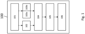
- Fig. 1 shows a positioning device 100 according to an embodiment of the present invention.
- the positioning device 100 is for calculating a position 106 of a mobile device.
- the positioning device 100 is configured to determine a measurement quality 102, and a reference signal type 103a and configuration 103b based on a positioning request 101.
- the positioning device 100 is also configured to determine a reference signal configuration request 104 based on at least the measurement quality 102, and the reference signal type 103a and configuration 103b, to obtain a measurement result 105 based on a reference signal configured according to the reference signal configuration request 104, and to calculate the position 106 based on at least the measurement result 105.
- the reference signal type 103a is a DL reference signal type in the invention. Alternatively, but not part of the invention, it can be at least one of an UL, reference signal type, or a SL reference signal type.
- the positioning device 100 can also be called positioning engine or "PosEng".
- the reference signal may also be called “RefSig”.
- a reference signal transmitter may be called “RefSig TX”
- a reference signal receiver may be called “RefSig RX”.
- the positioning request 101 may also be called location request.
- each of Fig. 2 to Fig 20 includes the function and features of the positioning device 100 as described in Fig. 1 . To this end, similar features are labelled with similar reference signs.
- Fig. 2 shows a schematic view of an operating manner of the positioning device 100.
- a generic signaling procedure for RAT-dependent positioning is depicted in Fig. 2 .
- the procedure can be characterized by the following steps:
- Each of the four functional blocks (i.e. the PosEng (that is, the positioning device 100), the RRC, the RefSig TX, and the RefSig RX) presented in Fig. 2 may be deployed/implemented in a different network entity, e.g. in the CN, in the radio access network (RAN), in a target UE or in a second UE.
- RAN radio access network
- Fig. 3 shows a schematic view of an operating manner of the positioning device 100, which can also be called downlink-assisted UE-based positioning.
- This manner refers to a system design where a target UE obtains radio signal measurements in downlink transmission and calculates its own position based on at least these RAT-based measurements.
- the positioning engine i.e. the positioning device 100
- the RAN controls the radio resource, therefore allocates a downlink radio resource for RAT-based measurements.
- the network provides the target UE positioning assistance in terms of assistance information and radio resource. Therefore, a charging policy may be applied.
- Fig. 4 shows a signaling procedure which is used for downlink-assisted UE-based positioning and which is performed by the positioning device 100.
- the steps of this procedure are the following:
- Fig. 5 shows a schematic view of an operating manner of the positioning device 100, which can also be called uplink-assisted UE-based positioning.
- This option refers to a system design where a target UE requests the uplink radio signal measurements and calculates its own position based on at least these RAT-based measurements.
- the positioning engine 100 is located in the target UE, that the RAN controls the radio resource, therefore allocates uplink radio resources for RAT-based measurements, and that the network provides the target UE positioning assistance in terms of assistance information and radio resource, therefore a charging policy may be applied.
- Fig. 6 shows a signaling procedure which is used for uplink-assisted UE-based positioning and which can be performed by the positioning device 100.
- the steps of this procedure are the following:
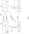
- Fig. 7 shows a schematic view of an operating manner of the positioning device 100, which can also be called sidelink-assisted network based positioning (CN-based).
- CN-based sidelink-assisted network based positioning
- This option refers to a system design where a location server in the CN or in a cloud collects any type of measurement and calculates the target UE position.
- the aim is to include sidelink measurements in addition to the prior-art types of measurements.
- the positioning engine 100 is implemented in the location server in CN or in the cloud. Further, the RAN controls the sidelink radio resources, therefore allocates sidelink radio resources for RAT-based measurements. Also the UEs support sidelink transmission and radio signal measurements.
- Fig. 8 shows a signaling procedure which is used for sidelink-assisted network based positioning and which can be performed by the positioning device 100.
- the steps of this procedure are the following:
- Fig. 9 shows a schematic view of an operating manner of the positioning device 100, which can also be called sidelink-assisted network-based positioning (RAN-based).
- RAN-based sidelink-assisted network-based positioning
- This option refers to a system design where a location server function is located in the RAN or in any entity associated with the RAN. The aim is to allow the location server function to obtain sidelink measurements.
- the positioning engine 100 is implemented in the RAN or in any entity associated with the RAN, such as a base station or a baseband unit. It is also assumed that the RAN controls the sidelink radio resource, therefore allocates sidelink radio resources for RAT-based measurements. Also, it is assumed that the UEs support sidelink transmission and radio signal measurements.
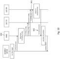
- Fig. 10 shows a signaling procedure which is used for sidelink-assisted network-based positioning (RAN-based) and which can be performed by the positioning device 100.
- the steps of this procedure are the following:
- Fig. 11 shows a schematic view of an operating manner of the positioning device 100, which can also be called sidelink-assisted UE-based Positioning (PosEng 100 at target UE).
- This option refers to a system design where the target UE obtains the radio signal measurements in the sidelink and calculates its own position based on at least the sidelink-based measurements.
- the positioning engine 100 is located in the target UE, that the target UE supports sidelink measurements, and that the sidelink radio resource is controlled by the RAN.
- Fig. 12 shows a signaling procedure which is used for sidelink-assisted UE-based Positioning (PosEng at target UE) and which can be performed by the positioning device 100.
- the steps of this procedure are the following:
- Fig. 13 shows a schematic view of an operating manner of the positioning device 100, which can also be called sidelink-assisted UE-based positioning (PosEng at a second UE).
- This option refers to a system design where a second UE with location server function, named a Master UE, obtains the radio signal measurements in the sidelink and calculates the target UE's position based on at least the sidelink-based measurements.
- the target UE cannot calculate the position, thus requests the Master UE.
- the Master UE decides which reference signal to be used.
- the positioning engine is located in the Master UE, that the Master UE collects any type or measurements and calculates the target UE's position based on the measurements, that the Master UE supports sidelink measurements, and that the sidelink radio resource is controlled by the RAN.
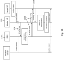
- Fig. 14 shows a signaling procedure which is used for sidelink-assisted UE-based Positioning (PosEng at a second UE) and which can be performed by the positioning device 100.
- the steps of this procedure are the following:
- Fig. 15 shows a schematic view of an operating manner of the positioning device 100, which can also be called sidelink-assisted UE-based positioning (RRC at target UE).
- RRC sidelink-assisted UE-based positioning
- This option refers to a system design where a target UE obtains radio signal measurements in the sidelink and calculates its own position based on at least the sidelink-based measurements.
- the positioning engine 100 is located in the target UE, that the sidelink radio resource is indirectly controlled by a RAN or out of the control of the RAN. Examples include using a resource pool and corresponding rules specified by the RAN for sidelink communication. However, the RAN is not involved in resource allocation for every single sidelink transmission. It is further assumed that the target UE takes control of the sidelink resource for reference signal transmission and supports sidelink measurements.
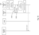
- Fig. 16 shows a signaling procedure which is used for sidelink-assisted UE-based positioning (RRC at target UE) and which can be performed by the positioning device 100.
- the steps of this procedure are the following:
- Fig. 17 shows a schematic view of an operating manner of the positioning device 100, which can also be called sidelink-assisted UE-based positioning (RRC at assist UE).
- RRC at assist UE refers to a system design where the target UE obtains the radio signal measurements in the sidelink and calculates its own position based on at least the sidelink-based measurements.
- the positioning engine is located in the target UE, that the sidelink radio resource is indirectly controlled by the RAN or out of the control of the RAN. Examples include using a resource pool and corresponding rules specified by the RAN for sidelink communication. However, RAN is not involved in resource allocation for every sidelink transmission. It is further assumed that the assist UE takes control of the sidelink resource for reference signal transmission, and that the target UE supports sidelink measurements.
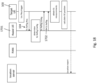
- Fig. 18 shows a signaling procedure which is used for sidelink-assisted UE-based positioning (RRC at assist UE) and which can be performed by the positioning device 100.
- the steps of this procedure are the following:
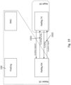
- Fig. 19 shows a schematic view of an operating manner of the positioning device 100, which can also be called Sidelink-assisted UE-based Positioning (PosEng at a second UE).
- This option refers to a system design where a Master UE with a location server function obtains radio signal measurements in the sidelink and calculates the target UE's position based on at least the sidelink-based measurements.
- the positioning engine is located in a Master UE, that the sidelink radio resource is indirectly controlled by the RAN or out of the control of the RAN. Examples include using a resource pool and corresponding rules specified by the RAN for sidelink communication.
- the RAN is not involved in resource allocation for every sidelink transmission.
- the Master UE takes control of the sidelink resource for reference signal transmission and supports sidelink measurements.
- Fig. 20 shows a signaling procedure which is used Sidelink-assisted UE-based positioning (RRC and PosEng at a second UE) and which can be performed by the positioning device 100.
- the steps of this procedure are the following:
- a location request generally may be regarded as a message sent by a location service client to a PosEng requesting any location-related service.
- a location service client to a PosEng requesting any location-related service.
- it may also include:
- a network/LTE-based method generally may imply that the PosEng is implemented in network/LTE.
- Downlink/uplink/sidelink-assist generally implies over which link the measurement is obtained.
- a RefSig request sent by the entity where PosEng is implemented may consist of at least one/some of the following information:
- a RefSig configuration sent by the RRC may consist of at least one/some of the following information:
- FIG. 21 shows a schematic view of an exemplary embodiment of the present invention, which is going to be described in the following.
- a location anchor service is going to be described.
- RAN elements like base stations or TRPs, whose geolocation are known, may serve as anchor points in GNSS-denied scenarios such as indoor or urban canyon.
- An LCS client may send a request for an anchor service from RAN.
- the request may consist of a number of anchors desired, and types and configuration of the RefSig required.
- the RAN shall determine the anchor TRPs from where the RefSig for positioning measurement can be scheduled.
- the network provider may apply a billing model for location anchor service. In such a way, the RAN elements transmit RefSig for positioning in an on-demand manner, enable the UE-type devices to obtain measurements.
- the positioning engine may retrieve these measurements and based on which derive the geolocation of the targets.
- the positioning engine is not necessarily part of the network provider.
- the positioning engine may fuse any types of measurements on hand, such as GPS/WiFi signals, sensors output, radar/Lidar, or camera, etc.
- This service enables efficient radio support for proprietary hybrid positioning methods and generates a new business model for network provider.
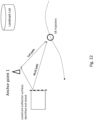
- FIG. 22 shows a schematic view of an exemplary embodiment of the present invention, which is going to be described in the following.
- simultaneous localization and mapping SLAM
- SLAM simultaneous localization and mapping
- SLAM which is traditionally applied for localizing a mobile robot in an unknown environment, functions by incrementally building a consistent map of this environment while simultaneously determining the robot's location within this map.
- a mapping application serving as a positioning engine, building up a landmark lists within the region of interest with the assistance of moving UEs.
- the positioning engine may request RefSig transmitted in certain directions so that a reflection path (NLoS path) can be measured. By continuously tracking the reflection path, this landmark can be identified, as illustrated in Fig. 22 .
- a moving UE identifies major transmission paths (LoS/NLoS) during the initial access (synchronization, beam-sweeping) phase.
- a PosEng may request, e.g. a beamformed RefSig transmitted to the direction of NLoS with its update period corresponding to the UE velocity.
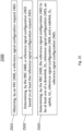
- Fig. 23 shows a method 2300 according partly to the present invention.
- the method 2300 is for operating the positioning device 100 and comprises a first step of determining 2301, by the positioning device 100, a measurement quality 102, and a reference signal type 103a and configuration 103b based on a location request 101.
- the method 2300 comprises a second step of determining 2302, by the positioning device 100, a reference signal configuration request 104 based on at least the measurement quality 102, and the reference signal type 103a and configuration 103b.
- the method 2300 comprises a third step of obtaining 2303, by the positioning device 100, a measurement result 105 based on a reference signal configured according to the reference signal configuration request 104.
- the method 2300 comprises a fourth step of calculating 2304, by the positioning device 100, the position 106, based on at least the measurement result 105.
- Fig. 24 shows a RRC 2400 according to an embodiment of the present invention.
- the RRC 2400 is configured to obtain a reference signal configuration request 2401, and to determine a reference signal configuration 2402 based on at least the reference signal configuration request 2401.
- the RRC 2400 is further configured to determine the reference signal configuration 2402 to be at least one of a downlink, DL, reference signal configuration 2403, an uplink, UL, reference signal configuration 2404, and a sidelink, SL, reference signal configuration 2405.
- Fig. 25 shows a method 2500 according to an embodiment of the present invention.
- the method 2500 is for operating the RRC 2400 and comprises a first step of obtaining 2501, by an RRC 2400, a reference signal configuration request 2401.
- the method 2500 comprises a second step of determining 2502, by the RRC 2400, a reference signal configuration 2402 based on at least the reference signal configuration request 2401.
- the method 2500 comprises a third step of determining 2503, by the RRC 2400, the reference signal configuration 2402 to be at least one of a downlink, DL, reference signal configuration 2403, an uplink, UL, reference signal configuration 2404, and a sidelink, SL, reference signal configuration 2405.
- Fig. 26 shows a system, e.g. a communication system, 2600 according to an embodiment of the present invention.
- the system is for position calculation of a mobile device (e.g. a UE), and comprises a positioning device 100 according to any one of Fig. 1 to Fig. 22 , a RRC 2400 according to Fig. 24 and/or at least one user equipment, UE.
Landscapes
- Engineering & Computer Science (AREA)
- Physics & Mathematics (AREA)
- General Physics & Mathematics (AREA)
- Radar, Positioning & Navigation (AREA)
- Remote Sensing (AREA)
- Computer Networks & Wireless Communication (AREA)
- Signal Processing (AREA)
- Position Fixing By Use Of Radio Waves (AREA)
- Mobile Radio Communication Systems (AREA)
Claims (4)
- Dispositif de positionnement (100) servant à calculer une position (106) d'un dispositif mobile, le dispositif de positionnement (100) étant configuré pour :- déterminer une qualité de mesure (102) ainsi qu'un type de signal de référence (103a) et une configuration (103b) sur la base d'une demande de positionnement (101),- déterminer une demande de configuration de signal de référence (104) sur la base, au moins, de la qualité de mesure (102) ainsi que du type de signal de référence (103a) et de la configuration (103b),- obtenir un résultat de mesure (105) sur la base d'un signal de référence configuré selon la demande de configuration de signal de référence (104),- calculer la position (106) sur la base, au moins, du résultat de mesure (105),le type de signal de référence (103a) étant un type de signal de référence DL, et la demande de configuration de signal de référence (104) comprenant une demande concernant un signal de référence DL, le dispositif de positionnement (100) étant en outre configuré pour :- envoyer la demande de configuration de signal de référence (104) à un contrôleur des ressources radio (RRC) (301),- recevoir une configuration de signal de référence DL (302),- recevoir un signal de référence DL (303) correspondant à la configuration de signal de référence (302), et- obtenir des mesures DL sur la base du signal de référence DL (303) reçu.
- Dispositif de positionnement (100) selon la revendication 1, dans lequel la demande de configuration de signal de référence (104) comprend une première configuration de rapport de mesure et/ou une configuration et/ou une périodicité et/ou un nombre de répétitions.
- Dispositif de positionnement (100) selon la revendication 1 ou 2, dans lequel la configuration de signal de référence (103b) comprend une seconde configuration de rapport de mesure et/ou une configuration accordée et/ou une périodicité et/ou un nombre de répétitions.
- Procédé (2300) de calcul d'une position (106) d'un dispositif mobile, le procédé (2300) comprenant les étapes consistant à :- déterminer (2301), par un dispositif de positionnement (100), une qualité de mesure (102) ainsi qu'un type de signal de référence (103a) et une configuration (103b) sur la base d'une demande de localisation (101),- déterminer (2302), par le dispositif de positionnement (100), une demande de configuration de signal de référence (104) sur la base, au moins, de la qualité de mesure (102) ainsi que du type de signal de référence (103a) et de la configuration (103b),- obtenir (2303), par le dispositif de positionnement (100), un résultat de mesure (105) sur la base d'un signal de référence configuré selon la demande de configuration de signal de référence (104),- calculer (2304), par le dispositif de positionnement (100), la position (106) sur la base, au moins, du résultat de mesure (105),le type de signal de référence (103a) étant un type de signal de référence DL, et la demande de configuration de signal de référence (104) comprenant une demande concernant un signal de référence DL,le procédé comprenant en outre les étapes consistant à : envoyer, par le dispositif de positionnement (100), la demande de configuration de signal de référence (104) à un contrôleur des ressources radio (RRC) (301) ; recevoir, par le dispositif de positionnement (100), une configuration de signal de référence DL (302) ; recevoir, par le dispositif de positionnement (100), un signal de référence DL (303) correspondant à la configuration de signal de référence (302) ; et obtenir, par le dispositif de positionnement (100), des mesures DL sur la base du signal de référence DL (303) reçu.
Applications Claiming Priority (1)
| Application Number | Priority Date | Filing Date | Title |
|---|---|---|---|
| PCT/EP2018/076422 WO2020064120A1 (fr) | 2018-09-28 | 2018-09-28 | Dispositif de positionnement et procédé de calcul d'une position d'un appareil mobile |
Publications (2)
| Publication Number | Publication Date |
|---|---|
| EP3847857A1 EP3847857A1 (fr) | 2021-07-14 |
| EP3847857B1 true EP3847857B1 (fr) | 2023-11-29 |
Family
ID=63708394
Family Applications (1)
| Application Number | Title | Priority Date | Filing Date |
|---|---|---|---|
| EP18779372.4A Active EP3847857B1 (fr) | 2018-09-28 | 2018-09-28 | Appareil de positionnement et procédé pour le calcul de la position d'un appareil mobile |
Country Status (4)
| Country | Link |
|---|---|
| US (1) | US11979793B2 (fr) |
| EP (1) | EP3847857B1 (fr) |
| CN (1) | CN112789912B (fr) |
| WO (1) | WO2020064120A1 (fr) |
Families Citing this family (53)
| Publication number | Priority date | Publication date | Assignee | Title |
|---|---|---|---|---|
| KR102708411B1 (ko) * | 2019-06-17 | 2024-09-23 | 엘지전자 주식회사 | Nr v2x에서 사이드링크 rtt를 이용한 포지셔닝 방법 및 장치 |
| WO2021061176A1 (fr) * | 2019-09-27 | 2021-04-01 | Nokia Technologies Oy | Procédé, appareil et programme informatique de localisation d'équipement utilisateur |
| WO2021092813A1 (fr) * | 2019-11-13 | 2021-05-20 | Nokia Shanghai Bell Co., Ltd. | Synchronisation précise de transmission de signal de référence de positionnement de liaison latérale |
| JP7455233B2 (ja) * | 2020-04-28 | 2024-03-25 | 華為技術有限公司 | 測位情報決定方法及び通信装置 |
| CN113709787A (zh) | 2020-05-20 | 2021-11-26 | 华为技术有限公司 | 一种管理上行测量的方法、装置和系统 |
| US11659515B2 (en) * | 2020-07-13 | 2023-05-23 | Mediatek Singapore Pte. Ltd. | Positioning methods facilitated by a server UE |
| CN116210288B (zh) * | 2020-07-31 | 2025-06-13 | 高通股份有限公司 | Ue到ue定位 |
| EP4191927A4 (fr) * | 2020-08-03 | 2024-08-28 | LG Electronics, Inc. | Procédé pour transmettre et recevoir un signal dans un système de communication sans fil, et appareil prenant en charge ce procédé |
| US12041511B2 (en) * | 2020-10-02 | 2024-07-16 | Qualcomm Incorporated | Measurement of a downlink positioning reference signal from a non-serving base station of a user equipment at a serving base station of the user equipment |
| US12535554B2 (en) | 2020-10-09 | 2026-01-27 | Nokia Technologies Oy | User equipment positioning |
| CN114599010A (zh) * | 2020-12-04 | 2022-06-07 | 维沃移动通信有限公司 | 副链路sl上的定位方法、装置及终端 |
| CN114982313B (zh) * | 2020-12-21 | 2025-12-30 | 北京小米移动软件有限公司 | 信息发送方法和装置、关系确定方法和装置 |
| CN114697903B (zh) * | 2020-12-30 | 2026-01-02 | 维沃移动通信有限公司 | 副链路sl上的定位方法、终端及网络侧设备 |
| US11609299B2 (en) * | 2021-02-02 | 2023-03-21 | Qualcomm Incorporated | Positioning reference signal measurement for joint positioning |
| CN116982361A (zh) | 2021-03-10 | 2023-10-31 | 华为技术有限公司 | 用于辅助在侧链路上定位的方法和装置 |
| JP7787900B2 (ja) * | 2021-03-18 | 2025-12-17 | クゥアルコム・インコーポレイテッド | サイドリンクユーザ機器識別測位 |
| CN115119139B (zh) * | 2021-03-18 | 2025-01-14 | 大唐移动通信设备有限公司 | 定位方法、装置、终端及存储介质 |
| US11638122B2 (en) | 2021-04-01 | 2023-04-25 | Nokia Technologies Oy | QoS associated on demand positioning signals for wireless networks |
| EP4071496A1 (fr) | 2021-04-06 | 2022-10-12 | Carrier Fire & Security EMEA BV | Procédés et systèmes de détection d'un objet |
| CN115250526B (zh) * | 2021-04-27 | 2025-08-05 | 大唐移动通信设备有限公司 | 终端设备的定位方法、装置及存储介质 |
| US12523736B2 (en) | 2021-05-10 | 2026-01-13 | Qualcomm Incorporated | On-demand positioning reference signal configuration |
| EP4349038B1 (fr) * | 2021-06-01 | 2026-04-29 | Sony Group Corporation | Procédés, dispositifs de communication, équipement d'infrastructure, et systèmes de télécommunications sans fil |
| WO2022258197A1 (fr) * | 2021-06-11 | 2022-12-15 | Nokia Technologies Oy | Gestion de signal de positionnement dans des réseaux aptes à une liaison latérale |
| CN117480825A (zh) * | 2021-06-22 | 2024-01-30 | 高通股份有限公司 | 用户设备发起的侧链路定位资源配置的选择 |
| EP4360372A1 (fr) * | 2021-06-22 | 2024-05-01 | Qualcomm Incorporated | Établissement de rapport d'équipement utilisateur de liaison latérale par l'intermédiaire d'une demande de données d'assistance pour le positionnement, et ses utilisations |
| WO2023272640A1 (fr) * | 2021-06-30 | 2023-01-05 | Oppo广东移动通信有限公司 | Procédé et appareil de positionnement de terminal, dispositif et support |
| CN117136599A (zh) * | 2021-07-12 | 2023-11-28 | Oppo广东移动通信有限公司 | 定位方法、装置、设备及介质 |
| EP4369818B1 (fr) * | 2021-07-27 | 2025-06-25 | Guangdong Oppo Mobile Telecommunications Corp., Ltd. | Procédé, appareil et dispositif d'acquisition d'emplacement, support, puce, produit et programme |
| US11641640B2 (en) | 2021-07-28 | 2023-05-02 | Qualcomm Incorporated | Sidelink-assisted position estimation procedure |
| CN117859379A (zh) * | 2021-08-30 | 2024-04-09 | Oppo广东移动通信有限公司 | 定位方法、终端和定位装置 |
| JP2023046094A (ja) * | 2021-09-22 | 2023-04-03 | 株式会社Soken | ユーザ装置、通信装置及び通信方法 |
| JP2023046097A (ja) * | 2021-09-22 | 2023-04-03 | 株式会社Soken | ユーザ装置及び通信方法 |
| JP2023046092A (ja) * | 2021-09-22 | 2023-04-03 | 株式会社Soken | ユーザ装置及び通信方法 |
| US12150010B2 (en) * | 2021-10-26 | 2024-11-19 | Qualcomm Incorporated | Priority assignment for sidelink-based positioning |
| DE102021130140A1 (de) | 2021-11-18 | 2023-05-25 | Audi Aktiengesellschaft | Verfahren und Ortungssystem zur Lokalisierung zumindest eines mobilen Systems sowie Produktionssystem mit zumindest einem fahrerlosen Transportfahrzeug |
| WO2023108631A1 (fr) * | 2021-12-17 | 2023-06-22 | Lenovo (Beijing) Limited | Procédés et appareils d'émission de signal de référence de positionnement de liaison latérale |
| KR20230103005A (ko) * | 2021-12-30 | 2023-07-07 | 주식회사 아이티엘 | 무선 통신 시스템에서 srs를 기반으로 사이드링크 포지셔닝을 수행하는 방법 및 장치 |
| KR20230103004A (ko) * | 2021-12-30 | 2023-07-07 | 주식회사 아이티엘 | 무선 통신 시스템에서 사이드링크 prs를 기반으로 포지셔닝을 수행하는 방법 및 장치 |
| CN116668937A (zh) * | 2022-02-18 | 2023-08-29 | 华为技术有限公司 | 一种定位信息传输方法、装置、存储介质和芯片系统 |
| CN116866820A (zh) * | 2022-03-28 | 2023-10-10 | 维沃移动通信有限公司 | 定位处理方法、装置、终端及网络侧设备 |
| CN116867058A (zh) * | 2022-03-28 | 2023-10-10 | 维沃移动通信有限公司 | 定位处理方法、装置、终端及网络侧设备 |
| US20250220622A1 (en) * | 2022-04-06 | 2025-07-03 | Beijing Xiaomi Mobile Software Co., Ltd. | Information determination method, information sending method, communication system, apparatus, and device |
| WO2023212355A1 (fr) * | 2022-04-28 | 2023-11-02 | Futurewei Technologies, Inc. | Initialisation de positionnement de liaison latérale dans des réseaux 5g |
| US20250294512A1 (en) * | 2022-05-06 | 2025-09-18 | Beijing Xiaomi Mobile Software Co., Ltd. | Ranging sidelink positioning method, and apparatus |
| CN119452595A (zh) * | 2022-07-05 | 2025-02-14 | Lg 电子株式会社 | 用于基于prs执行无线通信的方法和装置 |
| CN117500041A (zh) * | 2022-07-25 | 2024-02-02 | 北京三星通信技术研究有限公司 | 无线通信系统中用于定位的方法及装置 |
| EP4569852A1 (fr) * | 2022-08-12 | 2025-06-18 | Nokia Technologies Oy | Configuration de signal de référence de positionnement de liaison latérale |
| US12245101B2 (en) * | 2022-08-24 | 2025-03-04 | Qualcomm Incorporated | Location indication for uplink resources for positioning |
| US20260113161A1 (en) * | 2022-09-26 | 2026-04-23 | Sharp Kabushiki Kaisha | Sidelink positioning reference signal (sl-prs) capability communication to associate a device with a sidelink positioning group (spg) |
| EP4595467A1 (fr) * | 2022-09-30 | 2025-08-06 | Sony Group Corporation | Procédé et dispositif de coordination de positionnement de liaison latérale |
| CN120226418A (zh) * | 2022-12-02 | 2025-06-27 | 联想(北京)有限公司 | 用于混合定位的方法及设备 |
| WO2024183066A1 (fr) * | 2023-03-09 | 2024-09-12 | Nokia Shanghai Bell Co., Ltd. | Gestion de positionnement |
| WO2024229816A1 (fr) * | 2023-05-11 | 2024-11-14 | 北京小米移动软件有限公司 | Procédés de positionnement basés sur liaison latérale, et appareils |
Family Cites Families (14)
| Publication number | Priority date | Publication date | Assignee | Title |
|---|---|---|---|---|
| US9602990B2 (en) | 2011-04-11 | 2017-03-21 | Qualcomm Incorporated | Method for providing network-based measurements for user equipment-based positioning |
| US9432995B2 (en) * | 2011-04-18 | 2016-08-30 | Huawei Technologies Co., Ltd. | Method for arranging transmissions on a downlink carrier |
| CN103428749B (zh) * | 2012-05-18 | 2016-06-15 | 华为技术有限公司 | 一种下行多点信号质量测量方法和装置 |
| US9462448B2 (en) * | 2014-04-14 | 2016-10-04 | Qualcomm Incorporated | Adaptive positioning reference signal (PRS) for indoor location |
| US9713117B2 (en) * | 2014-09-25 | 2017-07-18 | Intel Corporation | Device-to-device assisted positioning in wireless cellular technologies |
| US9998856B2 (en) | 2016-05-13 | 2018-06-12 | Qualcomm Incorporated | Method and/or system for positioning of a mobile device |
| AR109331A1 (es) * | 2016-08-12 | 2018-11-21 | Ericsson Telefon Ab L M | Control de puntos de transmisión de referencia para mediciones rstd |
| US10420063B2 (en) * | 2017-02-02 | 2019-09-17 | Qualcomm Incorporated | On-demand user equipment positioning |
| US10070447B1 (en) * | 2017-03-02 | 2018-09-04 | Samsung Electronics Co., Ltd | Method and apparatus for enhanced reference (RSTD) measurement for long term evolution (LTE) positioning |
| CN107438258A (zh) * | 2017-06-05 | 2017-12-05 | 北京邮电大学深圳研究院 | 一种基于用户移动性管理的通信模式切换方法及装置 |
| CN113922938B (zh) * | 2017-11-17 | 2024-02-02 | 中兴通讯股份有限公司 | 一种参考信号信道特征配置方法和装置、及通信设备 |
| CN111566499A (zh) | 2018-04-13 | 2020-08-21 | 华为技术有限公司 | 用于确定目标用户设备的位置的设备和方法 |
| CN110557719B (zh) * | 2018-06-01 | 2021-03-30 | 电信科学技术研究院有限公司 | 定位方法及装置 |
| US11297589B2 (en) * | 2018-09-28 | 2022-04-05 | Qualcomm Incorporated | Systems and methods for network procedures for on-demand random access channel (RACH) |
-
2018
- 2018-09-28 WO PCT/EP2018/076422 patent/WO2020064120A1/fr not_active Ceased
- 2018-09-28 CN CN201880098272.6A patent/CN112789912B/zh active Active
- 2018-09-28 EP EP18779372.4A patent/EP3847857B1/fr active Active
-
2021
- 2021-03-26 US US17/213,646 patent/US11979793B2/en active Active
Also Published As
| Publication number | Publication date |
|---|---|
| CN112789912B (zh) | 2022-05-24 |
| EP3847857A1 (fr) | 2021-07-14 |
| US11979793B2 (en) | 2024-05-07 |
| CN112789912A (zh) | 2021-05-11 |
| WO2020064120A1 (fr) | 2020-04-02 |
| US20210219103A1 (en) | 2021-07-15 |
Similar Documents
| Publication | Publication Date | Title |
|---|---|---|
| US11979793B2 (en) | Positioning device and method for calculating a position of a mobile device | |
| US12452629B2 (en) | Apparatus for determining user position | |
| US20240430846A1 (en) | Systems and methods for positioning with channel measurements | |
| US12167298B2 (en) | Devices and methods for determining a position of a mobile terminal | |
| TWI786148B (zh) | 藉由一定位參考信號之波束成形以促進位置制定之系統及方法 | |
| US20220015059A1 (en) | Positioning methods facilitated by a server ue | |
| US20220070714A1 (en) | System and methods for rapid round-trip-time measurement | |
| US12439367B2 (en) | Determining a position of an entity of a wireless communication network | |
| Fischer | 5G NR positioning | |
| US8135416B2 (en) | Method and arrangement for determining terminal position | |
| US8914038B2 (en) | Method and arrangement for determining terminal position | |
| US20260095881A1 (en) | Combined one-to-many and many-to-one sidelink positioning | |
| EP4315892B1 (fr) | Appareil et procédé de transmission ou de réception d'une configuration de direction de faisceau | |
| WO2023195478A1 (fr) | Procédé et nœud de réseau | |
| JP2023531727A (ja) | 企業ネットワークについての位置ベースサービスのための方法および装置 | |
| EP4338325A1 (fr) | Appareil et procédé pour fournir, recevoir et utiliser une indication de caractéristiques de transmission pour des mesures de positionnement | |
| WO2023117057A1 (fr) | Dispositifs et procédés de positionnement de liaison latérale dans un réseau de communication mobile | |
| HK40017769B (zh) | 通过定位参考信号的波束成形以促进位置确定的系统及方法 | |
| HK40017769A (en) | Systems and methods to facilitate location determination by beamforming of a positioning reference signal |
Legal Events
| Date | Code | Title | Description |
|---|---|---|---|
| STAA | Information on the status of an ep patent application or granted ep patent |
Free format text: STATUS: UNKNOWN |
|
| STAA | Information on the status of an ep patent application or granted ep patent |
Free format text: STATUS: THE INTERNATIONAL PUBLICATION HAS BEEN MADE |
|
| PUAI | Public reference made under article 153(3) epc to a published international application that has entered the european phase |
Free format text: ORIGINAL CODE: 0009012 |
|
| STAA | Information on the status of an ep patent application or granted ep patent |
Free format text: STATUS: REQUEST FOR EXAMINATION WAS MADE |
|
| 17P | Request for examination filed |
Effective date: 20210407 |
|
| AK | Designated contracting states |
Kind code of ref document: A1 Designated state(s): AL AT BE BG CH CY CZ DE DK EE ES FI FR GB GR HR HU IE IS IT LI LT LU LV MC MK MT NL NO PL PT RO RS SE SI SK SM TR |
|
| DAV | Request for validation of the european patent (deleted) | ||
| DAX | Request for extension of the european patent (deleted) | ||
| STAA | Information on the status of an ep patent application or granted ep patent |
Free format text: STATUS: EXAMINATION IS IN PROGRESS |
|
| 17Q | First examination report despatched |
Effective date: 20220822 |
|
| GRAP | Despatch of communication of intention to grant a patent |
Free format text: ORIGINAL CODE: EPIDOSNIGR1 |
|
| STAA | Information on the status of an ep patent application or granted ep patent |
Free format text: STATUS: GRANT OF PATENT IS INTENDED |
|
| RIC1 | Information provided on ipc code assigned before grant |
Ipc: G01S 5/02 20100101ALI20230517BHEP Ipc: G01S 5/00 20060101ALI20230517BHEP Ipc: H04W 64/00 20090101AFI20230517BHEP |
|
| INTG | Intention to grant announced |
Effective date: 20230619 |
|
| GRAS | Grant fee paid |
Free format text: ORIGINAL CODE: EPIDOSNIGR3 |
|
| GRAA | (expected) grant |
Free format text: ORIGINAL CODE: 0009210 |
|
| STAA | Information on the status of an ep patent application or granted ep patent |
Free format text: STATUS: THE PATENT HAS BEEN GRANTED |
|
| AK | Designated contracting states |
Kind code of ref document: B1 Designated state(s): AL AT BE BG CH CY CZ DE DK EE ES FI FR GB GR HR HU IE IS IT LI LT LU LV MC MK MT NL NO PL PT RO RS SE SI SK SM TR |
|
| REG | Reference to a national code |
Ref country code: GB Ref legal event code: FG4D |
|
| REG | Reference to a national code |
Ref country code: CH Ref legal event code: EP |
|
| REG | Reference to a national code |
Ref country code: DE Ref legal event code: R096 Ref document number: 602018061860 Country of ref document: DE |
|
| REG | Reference to a national code |
Ref country code: IE Ref legal event code: FG4D |
|
| REG | Reference to a national code |
Ref country code: LT Ref legal event code: MG9D |
|
| REG | Reference to a national code |
Ref country code: NL Ref legal event code: MP Effective date: 20231129 |
|
| PG25 | Lapsed in a contracting state [announced via postgrant information from national office to epo] |
Ref country code: GR Free format text: LAPSE BECAUSE OF FAILURE TO SUBMIT A TRANSLATION OF THE DESCRIPTION OR TO PAY THE FEE WITHIN THE PRESCRIBED TIME-LIMIT Effective date: 20240301 |
|
| PG25 | Lapsed in a contracting state [announced via postgrant information from national office to epo] |
Ref country code: IS Free format text: LAPSE BECAUSE OF FAILURE TO SUBMIT A TRANSLATION OF THE DESCRIPTION OR TO PAY THE FEE WITHIN THE PRESCRIBED TIME-LIMIT Effective date: 20240329 |
|
| PG25 | Lapsed in a contracting state [announced via postgrant information from national office to epo] |
Ref country code: LT Free format text: LAPSE BECAUSE OF FAILURE TO SUBMIT A TRANSLATION OF THE DESCRIPTION OR TO PAY THE FEE WITHIN THE PRESCRIBED TIME-LIMIT Effective date: 20231129 |
|
| PG25 | Lapsed in a contracting state [announced via postgrant information from national office to epo] |
Ref country code: ES Free format text: LAPSE BECAUSE OF FAILURE TO SUBMIT A TRANSLATION OF THE DESCRIPTION OR TO PAY THE FEE WITHIN THE PRESCRIBED TIME-LIMIT Effective date: 20231129 |
|
| PG25 | Lapsed in a contracting state [announced via postgrant information from national office to epo] |
Ref country code: LT Free format text: LAPSE BECAUSE OF FAILURE TO SUBMIT A TRANSLATION OF THE DESCRIPTION OR TO PAY THE FEE WITHIN THE PRESCRIBED TIME-LIMIT Effective date: 20231129 Ref country code: IS Free format text: LAPSE BECAUSE OF FAILURE TO SUBMIT A TRANSLATION OF THE DESCRIPTION OR TO PAY THE FEE WITHIN THE PRESCRIBED TIME-LIMIT Effective date: 20240329 Ref country code: GR Free format text: LAPSE BECAUSE OF FAILURE TO SUBMIT A TRANSLATION OF THE DESCRIPTION OR TO PAY THE FEE WITHIN THE PRESCRIBED TIME-LIMIT Effective date: 20240301 Ref country code: ES Free format text: LAPSE BECAUSE OF FAILURE TO SUBMIT A TRANSLATION OF THE DESCRIPTION OR TO PAY THE FEE WITHIN THE PRESCRIBED TIME-LIMIT Effective date: 20231129 Ref country code: BG Free format text: LAPSE BECAUSE OF FAILURE TO SUBMIT A TRANSLATION OF THE DESCRIPTION OR TO PAY THE FEE WITHIN THE PRESCRIBED TIME-LIMIT Effective date: 20240229 |
|
| REG | Reference to a national code |
Ref country code: AT Ref legal event code: MK05 Ref document number: 1637399 Country of ref document: AT Kind code of ref document: T Effective date: 20231129 |
|
| PG25 | Lapsed in a contracting state [announced via postgrant information from national office to epo] |
Ref country code: NL Free format text: LAPSE BECAUSE OF FAILURE TO SUBMIT A TRANSLATION OF THE DESCRIPTION OR TO PAY THE FEE WITHIN THE PRESCRIBED TIME-LIMIT Effective date: 20231129 |
|
| PG25 | Lapsed in a contracting state [announced via postgrant information from national office to epo] |
Ref country code: SE Free format text: LAPSE BECAUSE OF FAILURE TO SUBMIT A TRANSLATION OF THE DESCRIPTION OR TO PAY THE FEE WITHIN THE PRESCRIBED TIME-LIMIT Effective date: 20231129 Ref country code: RS Free format text: LAPSE BECAUSE OF FAILURE TO SUBMIT A TRANSLATION OF THE DESCRIPTION OR TO PAY THE FEE WITHIN THE PRESCRIBED TIME-LIMIT Effective date: 20231129 Ref country code: PL Free format text: LAPSE BECAUSE OF FAILURE TO SUBMIT A TRANSLATION OF THE DESCRIPTION OR TO PAY THE FEE WITHIN THE PRESCRIBED TIME-LIMIT Effective date: 20231129 Ref country code: NO Free format text: LAPSE BECAUSE OF FAILURE TO SUBMIT A TRANSLATION OF THE DESCRIPTION OR TO PAY THE FEE WITHIN THE PRESCRIBED TIME-LIMIT Effective date: 20240229 Ref country code: NL Free format text: LAPSE BECAUSE OF FAILURE TO SUBMIT A TRANSLATION OF THE DESCRIPTION OR TO PAY THE FEE WITHIN THE PRESCRIBED TIME-LIMIT Effective date: 20231129 Ref country code: LV Free format text: LAPSE BECAUSE OF FAILURE TO SUBMIT A TRANSLATION OF THE DESCRIPTION OR TO PAY THE FEE WITHIN THE PRESCRIBED TIME-LIMIT Effective date: 20231129 Ref country code: HR Free format text: LAPSE BECAUSE OF FAILURE TO SUBMIT A TRANSLATION OF THE DESCRIPTION OR TO PAY THE FEE WITHIN THE PRESCRIBED TIME-LIMIT Effective date: 20231129 |
|
| PG25 | Lapsed in a contracting state [announced via postgrant information from national office to epo] |
Ref country code: DK Free format text: LAPSE BECAUSE OF FAILURE TO SUBMIT A TRANSLATION OF THE DESCRIPTION OR TO PAY THE FEE WITHIN THE PRESCRIBED TIME-LIMIT Effective date: 20231129 |
|
| PG25 | Lapsed in a contracting state [announced via postgrant information from national office to epo] |
Ref country code: CZ Free format text: LAPSE BECAUSE OF FAILURE TO SUBMIT A TRANSLATION OF THE DESCRIPTION OR TO PAY THE FEE WITHIN THE PRESCRIBED TIME-LIMIT Effective date: 20231129 Ref country code: AT Free format text: LAPSE BECAUSE OF FAILURE TO SUBMIT A TRANSLATION OF THE DESCRIPTION OR TO PAY THE FEE WITHIN THE PRESCRIBED TIME-LIMIT Effective date: 20231129 |
|
| PG25 | Lapsed in a contracting state [announced via postgrant information from national office to epo] |
Ref country code: SK Free format text: LAPSE BECAUSE OF FAILURE TO SUBMIT A TRANSLATION OF THE DESCRIPTION OR TO PAY THE FEE WITHIN THE PRESCRIBED TIME-LIMIT Effective date: 20231129 |
|
| PG25 | Lapsed in a contracting state [announced via postgrant information from national office to epo] |
Ref country code: SM Free format text: LAPSE BECAUSE OF FAILURE TO SUBMIT A TRANSLATION OF THE DESCRIPTION OR TO PAY THE FEE WITHIN THE PRESCRIBED TIME-LIMIT Effective date: 20231129 Ref country code: SK Free format text: LAPSE BECAUSE OF FAILURE TO SUBMIT A TRANSLATION OF THE DESCRIPTION OR TO PAY THE FEE WITHIN THE PRESCRIBED TIME-LIMIT Effective date: 20231129 Ref country code: RO Free format text: LAPSE BECAUSE OF FAILURE TO SUBMIT A TRANSLATION OF THE DESCRIPTION OR TO PAY THE FEE WITHIN THE PRESCRIBED TIME-LIMIT Effective date: 20231129 Ref country code: IT Free format text: LAPSE BECAUSE OF FAILURE TO SUBMIT A TRANSLATION OF THE DESCRIPTION OR TO PAY THE FEE WITHIN THE PRESCRIBED TIME-LIMIT Effective date: 20231129 Ref country code: EE Free format text: LAPSE BECAUSE OF FAILURE TO SUBMIT A TRANSLATION OF THE DESCRIPTION OR TO PAY THE FEE WITHIN THE PRESCRIBED TIME-LIMIT Effective date: 20231129 Ref country code: DK Free format text: LAPSE BECAUSE OF FAILURE TO SUBMIT A TRANSLATION OF THE DESCRIPTION OR TO PAY THE FEE WITHIN THE PRESCRIBED TIME-LIMIT Effective date: 20231129 Ref country code: CZ Free format text: LAPSE BECAUSE OF FAILURE TO SUBMIT A TRANSLATION OF THE DESCRIPTION OR TO PAY THE FEE WITHIN THE PRESCRIBED TIME-LIMIT Effective date: 20231129 Ref country code: AT Free format text: LAPSE BECAUSE OF FAILURE TO SUBMIT A TRANSLATION OF THE DESCRIPTION OR TO PAY THE FEE WITHIN THE PRESCRIBED TIME-LIMIT Effective date: 20231129 |
|
| PG25 | Lapsed in a contracting state [announced via postgrant information from national office to epo] |
Ref country code: PT Free format text: LAPSE BECAUSE OF FAILURE TO SUBMIT A TRANSLATION OF THE DESCRIPTION OR TO PAY THE FEE WITHIN THE PRESCRIBED TIME-LIMIT Effective date: 20240401 |
|
| PG25 | Lapsed in a contracting state [announced via postgrant information from national office to epo] |
Ref country code: PT Free format text: LAPSE BECAUSE OF FAILURE TO SUBMIT A TRANSLATION OF THE DESCRIPTION OR TO PAY THE FEE WITHIN THE PRESCRIBED TIME-LIMIT Effective date: 20240401 |
|
| REG | Reference to a national code |
Ref country code: DE Ref legal event code: R097 Ref document number: 602018061860 Country of ref document: DE |
|
| PLBE | No opposition filed within time limit |
Free format text: ORIGINAL CODE: 0009261 |
|
| STAA | Information on the status of an ep patent application or granted ep patent |
Free format text: STATUS: NO OPPOSITION FILED WITHIN TIME LIMIT |
|
| PG25 | Lapsed in a contracting state [announced via postgrant information from national office to epo] |
Ref country code: SI Free format text: LAPSE BECAUSE OF FAILURE TO SUBMIT A TRANSLATION OF THE DESCRIPTION OR TO PAY THE FEE WITHIN THE PRESCRIBED TIME-LIMIT Effective date: 20231129 |
|
| PG25 | Lapsed in a contracting state [announced via postgrant information from national office to epo] |
Ref country code: SI Free format text: LAPSE BECAUSE OF FAILURE TO SUBMIT A TRANSLATION OF THE DESCRIPTION OR TO PAY THE FEE WITHIN THE PRESCRIBED TIME-LIMIT Effective date: 20231129 |
|
| 26N | No opposition filed |
Effective date: 20240830 |
|
| PG25 | Lapsed in a contracting state [announced via postgrant information from national office to epo] |
Ref country code: MC Free format text: LAPSE BECAUSE OF FAILURE TO SUBMIT A TRANSLATION OF THE DESCRIPTION OR TO PAY THE FEE WITHIN THE PRESCRIBED TIME-LIMIT Effective date: 20231129 |
|
| REG | Reference to a national code |
Ref country code: CH Ref legal event code: PL |
|
| PG25 | Lapsed in a contracting state [announced via postgrant information from national office to epo] |
Ref country code: LU Free format text: LAPSE BECAUSE OF NON-PAYMENT OF DUE FEES Effective date: 20240928 |
|
| REG | Reference to a national code |
Ref country code: BE Ref legal event code: MM Effective date: 20240930 |
|
| PG25 | Lapsed in a contracting state [announced via postgrant information from national office to epo] |
Ref country code: BE Free format text: LAPSE BECAUSE OF NON-PAYMENT OF DUE FEES Effective date: 20240930 |
|
| PG25 | Lapsed in a contracting state [announced via postgrant information from national office to epo] |
Ref country code: FR Free format text: LAPSE BECAUSE OF NON-PAYMENT OF DUE FEES Effective date: 20240930 |
|
| PG25 | Lapsed in a contracting state [announced via postgrant information from national office to epo] |
Ref country code: CH Free format text: LAPSE BECAUSE OF NON-PAYMENT OF DUE FEES Effective date: 20240930 |
|
| PG25 | Lapsed in a contracting state [announced via postgrant information from national office to epo] |
Ref country code: IE Free format text: LAPSE BECAUSE OF NON-PAYMENT OF DUE FEES Effective date: 20240928 |
|
| PG25 | Lapsed in a contracting state [announced via postgrant information from national office to epo] |
Ref country code: FI Free format text: LAPSE BECAUSE OF FAILURE TO SUBMIT A TRANSLATION OF THE DESCRIPTION OR TO PAY THE FEE WITHIN THE PRESCRIBED TIME-LIMIT Effective date: 20231129 |
|
| PGFP | Annual fee paid to national office [announced via postgrant information from national office to epo] |
Ref country code: DE Payment date: 20250805 Year of fee payment: 8 |
|
| PGFP | Annual fee paid to national office [announced via postgrant information from national office to epo] |
Ref country code: GB Payment date: 20250807 Year of fee payment: 8 |
|
| PG25 | Lapsed in a contracting state [announced via postgrant information from national office to epo] |
Ref country code: CY Free format text: LAPSE BECAUSE OF FAILURE TO SUBMIT A TRANSLATION OF THE DESCRIPTION OR TO PAY THE FEE WITHIN THE PRESCRIBED TIME-LIMIT; INVALID AB INITIO Effective date: 20180928 |
|
| PG25 | Lapsed in a contracting state [announced via postgrant information from national office to epo] |
Ref country code: HU Free format text: LAPSE BECAUSE OF FAILURE TO SUBMIT A TRANSLATION OF THE DESCRIPTION OR TO PAY THE FEE WITHIN THE PRESCRIBED TIME-LIMIT; INVALID AB INITIO Effective date: 20180928 |