EP3848099B1 - Talon pourvu de cale de montée pour une fixation de randonnée - Google Patents
Talon pourvu de cale de montée pour une fixation de randonnée Download PDFInfo
- Publication number
- EP3848099B1 EP3848099B1 EP21150725.6A EP21150725A EP3848099B1 EP 3848099 B1 EP3848099 B1 EP 3848099B1 EP 21150725 A EP21150725 A EP 21150725A EP 3848099 B1 EP3848099 B1 EP 3848099B1
- Authority
- EP
- European Patent Office
- Prior art keywords
- climbing aid
- heel unit
- touring
- heel
- climbing
- Prior art date
- Legal status (The legal status is an assumption and is not a legal conclusion. Google has not performed a legal analysis and makes no representation as to the accuracy of the status listed.)
- Active
Links
Images



Classifications
-
- A—HUMAN NECESSITIES
- A63—SPORTS; GAMES; AMUSEMENTS
- A63C—SKATES; SKIS; ROLLER SKATES; DESIGN OR LAYOUT OF COURTS, RINKS OR THE LIKE
- A63C9/00—Ski bindings
- A63C9/006—Ski bindings with a climbing wedge
Definitions
- the present invention relates to a heel unit for a touring binding, comprising a binding body which is suitable for holding a heel section of a touring boot in a downhill position of the heel unit and for releasing the heel section of the touring boot in a touring position of the heel unit so that the touring boot can lift off the heel unit, and a climbing aid which is adjustable between an active position and a passive position, wherein in the touring position of the heel unit the climbing aid in its active position supports the heel section of the touring boot at a predetermined height above a gliding board plane.
- the present invention further relates to a heel unit for a touring binding, comprising a binding body which is suitable for holding a heel section of a touring boot in a downhill position of the heel unit and for releasing the heel section of the touring boot in a touring position of the heel unit so that the touring boot can lift off the heel unit, a first climbing aid which is adjustable between an active position and a passive position, wherein in the touring position of the heel unit the first climbing aid in its active position supports the heel section of the touring boot at a predetermined height above a gliding board plane, and a second climbing aid which is adjustable between an active position and a passive position, wherein in the touring position of the heel unit the second climbing aid in its active position supports the heel section of the touring boot at a predetermined height above a gliding board plane which is higher than the predetermined height of the first climbing aid.
- the EP 2 281 616 A2 an electronic climbing aid that can be locked or released in different positions by an adjusting element in order to be able to adjust the height of a support surface of the climbing aid above a sliding board level.
- the DE 10 2016 006 850 A1 discloses a ski binding with a heel holder that can be pivoted about an axis parallel to a gliding board plane and perpendicular to a gliding board longitudinal direction and has a section that functions as a climbing aid and can be activated by the pivoting movement of the heel holder in order to provide a climbing aid.
- the US 5,318,320 A discloses a ski binding with a pivoting heel holder which has a section acting as a climbing aid.
- a climbing aid is used in ski mountaineering to compensate for changes in the gradient of the terrain when walking.
- Steep terrain can be compensated for by switching on the climbing aid and thus increasing the support height for a heel section of a touring boot.
- Conventional touring bindings often have one or two climbing aids, so that in addition to a so-called zero position, in which no climbing aid is switched on and a heel section of the touring boot rests directly on a ski, a base or a brake pedal of the heel unit of the touring binding, one or two further support heights can be set by the user adjusting the climbing aid from a passive position to an active position.
- the climbing aid is often pivoted on the binding body of the heel unit and must be pivoted by the user into the active position by hand or with a ski pole in order to be adjusted from the passive position to the active position.
- the user must guide the climbing aid, particularly by pulling it with a ski pole, along the entire movement path or a large part of the movement path from the passive position to the active position.
- This adjustment can be quite difficult, especially since climbing aids are made of smaller and more difficult to grip components in order to save weight.
- the second climbing aid is often also pivotally mounted on the binding body, preferably on the same axis as the first climbing aid.
- the problems mentioned above also occur when adjusting the second climbing aid from the passive position to the active position.
- a further disadvantage can be that when the user intentionally adjusts the first climbing aid from the passive position to the active position, the second climbing aid is also accidentally grabbed and adjusted, meaning that the correct support height for the touring boot heel section cannot be found straight away.
- Heel units with other types of climbing aids are also known, but all of these are either difficult to use or have complex, relatively heavy and/or expensive to manufacture arrangements, for example pneumatic, hydraulic and/or electronic.
- a heel unit for a touring binding which enables simplified operation of one or possibly several climbing aids, which is comparatively simple in construction and has a low weight.
- the object underlying the invention is achieved by a heel unit for a touring binding according to claim 1.
- the climbing aid is pre-tensioned in the active position over the entire movement path and can also be locked in the passive position, it is sufficient To adjust the climbing aid from the locked, passive position to the active position, this lock must be released in order to achieve an adjustment.
- the climbing aid no longer has to be guided over its entire path of movement or part of its path of movement, but it is sufficient to release a locking mechanism, which can be a latching or hook mechanism, for example. All locking options are conceivable here.
- the lock can be released by pressing on the climbing aid with a ski pole, for example.
- pre-tensioning the climbing aid into the active position the climbing aid moves into the active position by itself after the lock is released.
- the adjustment of the climbing aid is therefore semi-automatic, so to speak, and operating the climbing aid is advantageously simplified.
- a pivoting version of the climbing aid offers the advantages of easy operation and the possibility of a space-saving arrangement.
- the preload into the active position can advantageously be achieved by a leg spring as an elastic element, which requires less installation space compared to other springs, such as compression or tension springs.
- the climbing aid can also be arranged so that it can be moved linearly on the heel unit, in particular on the binding body.
- a climbing aid that can be moved lengthways in the direction of the ski is intended here, which can be easily pushed forward after the lock is released in order to be brought into the active position. Operating a longitudinally movable climbing aid is also very simple.
- the climbing aid can be a first climbing aid and the heel unit can further comprise a second climbing aid which is adjustable between an active position and a passive position, wherein in the Touring position of the heel unit, the second climbing aid in its active position supports the heel section of the touring boot at a predetermined height above a gliding board level which is higher than the predetermined height of the first climbing aid.
- the second climbing aid can be mounted on the first climbing aid.
- Such an arrangement can in turn advantageously simplify operation of the climbing aids.
- the second climbing aid is mounted on an axis relatively far away from the ski, it can be designed to be smaller and therefore lighter, since less additional height has to be achieved from the high point on the first climbing aid for the support surface of the second climbing aid.
- the first climbing aid can be locked in the passive position by means of the second climbing aid.
- both climbing aids can advantageously be locked in the passive position by just one locking mechanism.
- the first climbing aid and/or the elastic element can be designed to transfer the second climbing aid into a standby position when the first climbing aid is adjusted from the passive position to the active position, which is located between the passive position and the active position of the second climbing aid. If the first climbing aid takes the second climbing aid along part of the path of movement when the first climbing aid is adjusted from the passive position to the active position, i.e. transfers the second climbing aid into a standby position, a shorter path must be overcome to adjust the second climbing aid into the active position.
- the second climbing aid can protrude from the heel unit or the binding body in the standby position and thus be easier to grip or operate, while in the passive position it is advantageously close to the binding body. In this way, operation of the second climbing aid can be simplified by moving it into the ready position when adjusting the first climbing aid.
- the elastic element can preferably provide a spring force for both the first climbing aid and the second climbing aid. In this way, only one spring is required for both climbing aids and costs and weight can be saved.
- the elastic element can transmit the spring force for the first climbing aid directly by being arranged on the first climbing aid, and transmit the spring force for the second climbing aid indirectly by being arranged on the first climbing aid and transmitting the spring force to the second climbing aid via the first climbing aid.
- the second climbing aid can be pre-tensioned into the active position by the elastic element, for example.
- the second climbing aid can assume a stable position in the standby position, in particular by an interaction of a fitting surface of the second climbing aid with a fitting surface of the binding body or the like and the elastic element. The exact position of the standby position can be set by an angle of the fitting surface of the binding body.
- the object underlying the invention is achieved by a heel unit for a touring binding according to claim 8.
- the first climbing aid takes the second climbing aid along part of the path of movement when the first climbing aid is adjusted from the passive position to the active position, i.e. if the second climbing aid is moved into a standby position, a shorter path must be overcome to adjust the second climbing aid to the active position.
- the second climbing aid can protrude from the heel unit or the binding body in the standby position and thus be easier to grip or operate. while in the passive position it can advantageously lie close to the binding body. In this way, operation of the second climbing aid is simplified by moving it into the ready position when adjusting the first climbing aid.
- the first climbing aid is pre-tensioned by means of the elastic element, either in its passive position or in its active position. If the first climbing aid exceeds the dead center at which the elastic element is most compressed when adjusting from the passive position to the active position, it "snaps" into the active position. Conversely, if the first climbing aid exceeds the dead center when adjusting from the active position to the passive position, it "snaps" into the passive position. This extremely intuitive operation means that user comfort can be further improved with this design.
- the first climbing aid can be pivotably mounted on the heel unit, in particular on the binding body.
- a pivotable design of the climbing aid can bring with it the advantages of being easy to use and the possibility of a space-saving arrangement.
- the preload in the active position can advantageously be achieved by a leg spring as an elastic element, which requires less installation space compared to other springs, such as compression or tension springs.
- the first climbing aid can be mounted on the heel unit, in particular on the binding body, in a linearly displaceable manner.
- a climbing aid that can be displaced longitudinally in the direction of the ski is envisaged here, which can be easily pushed forward after the lock is released in order to be brought into the active position.
- the operation of a longitudinally displaceable climbing aid is also very simple.
- the second climbing aid can be mounted on the first climbing aid.
- Such an arrangement can in turn advantageously simplify operation of the climbing aids.
- the second climbing aid can be made smaller and therefore lighter if it is mounted on an axis that is relatively far away from the ski, since less additional height has to be achieved from the high point on the first climbing aid for the support surface of the second climbing aid.
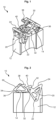
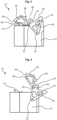
- the Figures 1 to 6 show a heel unit 10 according to a first embodiment of the present invention.
- the heel unit 10 comprises a binding body 12 and a climbing aid 20, which can be pivotally mounted on the binding body 12, in particular on an axis 22.
- the binding body 12 is suitable for holding a heel section of a touring boot (not shown) in a downhill position of the heel unit 10 and for releasing the heel section of the touring boot in a touring position of the heel unit 10, so that the touring boot can lift off the heel unit 10.
- the climbing aid 20 is adjustable between an active position, which is in the Figures 4 to 6 shown, and a passive position adjustable, which in the Figures 1 and 2 is shown.
- the climbing aid 20 in its active position supports the heel section of the touring boot at a predetermined height above a sliding board plane.
- the climbing aid 20 is pre-tensioned into the active position over its entire movement path by means of an elastic element (not shown).
- the elastic element can be implemented, for example, by a leg spring which is arranged on the axis 22 and transmits a spring force to the binding body 12 and to the climbing aid 20.
- other types of springs or other types of elastic elements are also conceivable in order to pre-tension the climbing aid 20 into the active position.
- the climbing aid 20 can be locked in the passive position, for example by means of locking projections or the like.
- the climbing aid 20 can be a first climbing aid 20 and a second climbing aid 30 can also be provided, which is also adjustable between an active position and a passive position, wherein in the touring position of the heel unit 10, the second climbing aid 30 in its active position supports the heel section of the touring boot at a predetermined height which is higher than the predetermined height of the first climbing aid 20.
- the second climbing aid 30 can be pivotally mounted on the first climbing aid 20 on an axis 32.
- the individual figures show a transition of the climbing aid 20 from the passive position to the active position.
- FIG. 1 and 2 a perspective view and a side view of the heel unit 10 according to the first embodiment with the first climbing aid 20 in the passive position and the second climbing aid 30 in the passive position are shown.
- the first climbing aid 20 can be locked in the passive position by means of the second climbing aid 30. Locking can be carried out, for example, by a locking projection 14 provided on the binding body 12 and a projection 36 provided on the second climbing aid 30, which engages with the locking projection 14.
- a projection provided on the first climbing aid 20 to engage with a locking projection provided on the binding body 12 in order to lock the first climbing aid 20 in the passive position.
- several locking projections and Complementary projections can be provided to lock the first climbing aid 20 and/or the second climbing aid 30 in the passive position.
- the locking which takes place via the second climbing aid 30 mounted on the first climbing aid 20, can be released by pressing either on the unlocking extension 38 on the second climbing aid 30 or on the unlocking surface 40 on the second climbing aid 30. This can be done by hand or with a ski pole, for example. In both options, the engagement between the projection 36 and the locking projection 14 and thus the locking of the first climbing aid 20 and the second climbing aid 30 can be released.
- FIG 3 a position of the climbing aids 20, 30 is shown shortly after the engagement between the projection 36 and the locking projection 14 has been released. Since the first climbing aid 20 is pre-tensioned into the active position over its entire movement path, it moves into the active position after the locking mechanism has been released. This is shown in Figure 4 shown.
- the heel section of the touring boot can be supported on a support surface 24 of the first climbing aid 20 at the predetermined height above the gliding board level.
- the elastic element can advantageously provide a spring force for both the first climbing aid 20 and the second climbing aid 30.
- this is achieved by the second climbing aid 30 being mounted on the first climbing aid 20, on which in turn the elastic element acts in the form of the leg spring (not shown).
- a fitting surface 42 of the second climbing aid 30 is pressed against an opposite fitting surface 16 of the binding body 12 by this spring force and the second climbing aid 30 is thereby held spring-loaded in a ready position in which it protrudes upwards from the binding body 12.
- This allows operation of the second climbing aid 30 or an adjustment of the second climbing aid 30 into its active position can be made considerably easier.
- the exact position of the ready position of the second climbing aid can be adjusted by an angle of the fitting surface 16 of the binding body 12.
- the second climbing aid 30 In order to adjust the second climbing aid 30 to the active position, it simply has to be moved from the standby position to the active position, for example by hand or ski pole. As soon as an edge between the fitting surface 40 and the release surface 42, which can slide over the fitting surface 16 of the binding body 12 during this adjustment, exceeds a certain point, the spring force of the elastic element can also pre-tension the second climbing aid 30 into the active position.
- This position is in Figure 5 as a side view of the heel unit 10 and in Figure 6 shown as a sectional view of the heel unit 10.
- the release surface 40 of the second climbing aid 30 can be pressed against the fitting surface 16 of the binding body 12 in order to hold the second climbing aid 30 in the active position by the spring force of the elastic element.
- the heel section of the touring boot can be supported on a support surface 34 of the second climbing aid 30 at the predetermined height above the gliding board level, which is higher than the predetermined height of the first climbing aid 20.
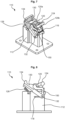
- the Figures 7 to 10 show a heel unit 110 according to a second embodiment of the present invention.
- the heel unit 110 comprises a binding body 112, a first climbing aid 120 and optionally a second climbing aid 130.
- the binding body 112 is suitable for holding a heel section of a touring boot (not shown) in a downhill position of the heel unit 110 and for releasing the heel section of the touring boot in a touring position of the heel unit 110, so that the touring boot can lift off the heel unit 110.
- the first climbing aid 120 is between an active position, which is in the Figures 9 and 10 shown, and a passive position adjustable, which in the Figures 7 and 8
- the first climbing aid 120 in its active position supports the heel section of the touring boot at a predetermined height above a gliding board plane.
- the second climbing aid 130 is between an active position, which is Figure 10 shown, and a passive position adjustable, which in the Figures 7 and 8 is shown.
- the second climbing aid 130 in its active position supports the heel section of the touring boot at a predetermined height above a gliding board plane, which is higher than the predetermined height of the first climbing aid 120.
- the first climbing aid 120 is pre-tensioned into the active position over its entire movement path by means of an elastic element (not shown).
- the elastic element can be implemented, for example, by a leg spring, a compression spring or a tension spring.
- the first climbing aid 120 can be locked in the passive position, for example, by means of locking projections or the like. Locking can be achieved, for example, by means of a locking projection 114 provided on the binding body 112 and a driver projection 126 provided on the first climbing aid 120, which engages with the locking projection 114.
- Several locking projections and projections designed to complement them can also be provided in order to lock the first climbing aid 120 and/or the second climbing aid 130 in the passive position.
- the first climbing aid 120 can also be designed to transfer the second climbing aid 130 into a standby position when the first climbing aid 120 is adjusted from the passive position to the active position, which is located between the passive position and the active position of the second climbing aid 130.
- the standby position of the second climbing aid 130 which is in Figure 9
- the second climbing aid 130 advantageously protrude upwards from the binding body 112 and is thus easier to grip or operate, while in the passive position it can advantageously lie close to the binding body 112. In this way, operation of the second climbing aid 130 is simplified.
- a shorter path has to be overcome to adjust the second climbing aid 130 to the active position.
- the first climbing aid 120 can take the second climbing aid 130 with it into the standby position via the driver projection 126, which rests on a surface of the second climbing aid 130, when the first climbing aid 120 is adjusted from the passive position to the active position.
- the first climbing aid 120 can be constructed from a first part 120a and a second part 120b.
- the first part 120a of the first climbing aid 120 can be mounted on the heel unit 110, in particular on the binding body 112, in a sliding, linearly displaceable manner in longitudinal grooves 116 formed in the binding body 112.
- the second part 120b of the first climbing aid 120 can be pivotally mounted on an axis 122 formed on the first part 120a of the first climbing aid 120.
- the first climbing aid 120 can be adjusted from the passive position to the active position by releasing the locking mechanism of the first climbing aid 120, the first part 120a of the first climbing aid 120 sliding forwards in the longitudinal direction of the ski and the second part 120b of the first climbing aid 120 pivoting forwards about the axis 122 and thereby taking the second climbing aid 130 into the standby position. This position is in Figure 9 shown.
- An axle 132 of the second climbing aid 130 can be mounted in grooves 118 formed on both sides of the binding body 112 so that they can be displaced longitudinally in the longitudinal direction of the ski and can also be connected to the first climbing aid 120 via tabs 150 formed on both sides. These tabs 150 can in particular be mounted at one end on the axle 122 of the first climbing aid 120 and at an opposite end on the axle 132 of the second climbing aid 130. For example, this makes it possible to that the elastic element can provide a spring force for both the first climbing aid 120 and the second climbing aid 130.
- the individual figures show a transition of the first climbing aid 120 from the passive position to the active position as well as a transition of the second climbing aid 130 from the passive position to the standby position and the active position.
- FIG. 7 and 8 a perspective view and a side view of the heel unit 110 according to the second embodiment with the first climbing aid 120 in the passive position and the second climbing aid 130 in the passive position are shown.
- FIG 9 is a side view of the heel unit 110 according to the second embodiment with the first climbing aid 120 in the active position and the second climbing aid 130 in the standby position. It can be seen that the heel section of the touring boot can be supported at the predetermined height above the gliding board level on a support surface 124 of the first climbing aid 120 in the touring position of the heel unit 110 in the active position of the first climbing aid 120.
- the second climbing aid 130 protrudes upwards and is easy to grip and operate.
- FIG 10 is a side view of the heel unit 110 according to the third embodiment with the first climbing aid 120 in the active position and the second climbing aid 130 in the active position.
- the heel section of the touring boot can be supported on a support surface 134 of the second climbing aid 130 at the predetermined height above the gliding board level, which is higher than the predetermined height of the first climbing aid 120.
- the Figures 11 to 14 show a heel unit 210 according to a third embodiment of the present invention.
- the heel unit 210 comprises a binding body 212, a first climbing aid 220 and a second climbing aid 230.
- the binding body 212 is suitable for holding a heel section of a touring boot (not shown) in a downhill position of the heel unit 210 and for releasing the heel section of the touring boot in a touring position of the heel unit 210 so that the touring boot can lift off the heel unit 210.
- the first climbing aid 220 is adjustable between an active position, which is in the Figures 13 and 14 shown, and a passive position adjustable, which in the Figures 11 and 12
- the first climbing aid 220 in its active position supports the heel section of the touring boot at a predetermined height above a gliding board plane.
- the second climbing aid 230 is between an active position, which is Figure 14 shown, and a passive position adjustable, which in the Figures 11 and 12 is shown.
- the second climbing aid 230 in its active position supports the heel section of the touring boot at a predetermined height above a gliding board level, which is higher than the predetermined height of the first climbing aid 220.
- the first climbing aid 220 is designed to transfer the second climbing aid 230 into a standby position when the first climbing aid 220 is adjusted from the passive position to the active position, which is located between the passive position and the active position of the second climbing aid 230.
- the second climbing aid 230 can advantageously protrude upwards from the binding body 212 and is thus easier to grip or operate, while in the passive position it can advantageously lie close to the binding body 212. In this way, operation of the second climbing aid 230 is simplified.
- the second climbing aid 230 is a shortened path to be overcome in the active position.
- the first climbing aid 220 can have a driver projection 226, which rests on a surface of the second climbing aid 230 and takes it with it into the standby position when the first climbing aid 220 is adjusted from the passive position to the active position.
- the first climbing aid 220 and/or the second climbing aid 230 can be pivotally mounted on the heel unit, in particular on the binding body 212. In the third embodiment, both the first climbing aid 220 and the second climbing aid 230 can be mounted on an axle 222.
- the first climbing aid 220 and/or the second climbing aid 230 can be pre-tensioned into the active position and/or the passive position via a resilient projection 240, which can be provided in particular on the binding body 212 and which interacts with lower ends of the first climbing aid 220 and/or the second climbing aid 230, or via another spring element.
- the individual figures show a transition of the first climbing aid 220 from the passive position to the active position as well as a transition of the second climbing aid 230 from the passive position to the standby position and the active position.
- FIG. 11 and 12 a perspective view and a side view of the heel unit 210 according to the third embodiment with the first climbing aid 220 in the passive position and the second climbing aid 230 in the passive position are shown.
- FIG 13 is a side view of the heel unit 210 according to the third embodiment with the first climbing aid 220 in the active position and the second climbing aid 230 is shown in the ready position. It can be seen that in the touring position of the heel unit 210 in the active position of the first climbing aid 220, the heel section of the touring boot can be supported at the predetermined height above the gliding board level on a support surface 224 of the first climbing aid 220. The second climbing aid 230 protrudes upwards and is easy to grip and operate.
- FIG 14 is a side view of the heel unit 210 according to the third embodiment with the first climbing aid 220 in the active position and the second climbing aid 230 in the active position.
- the heel section of the touring boot can be supported on a support surface 234 of the second climbing aid 230 at the predetermined height above the gliding board level, which is higher than the predetermined height of the first climbing aid 220.
- the Figures 15 to 18 show a heel unit 310 according to a fourth embodiment of the present invention.
- the heel unit 310 comprises a binding body 312, a first climbing aid 320 and a second climbing aid 330.
- the binding body 312 is suitable for holding a heel section of a touring boot (not shown) in a downhill position of the heel unit 310 and for releasing the heel section of the touring boot in a touring position of the heel unit 310 so that the touring boot can lift off the heel unit 310.
- the first climbing aid 320 is adjustable between a passive position, which is in the Figures 15 and 16 shown, and an active position adjustable, which in Figure 18
- the first climbing aid 320 in its active position supports the heel section of the touring boot on a support surface 324 at a predetermined height above a gliding board plane.
- the second climbing aid 330 is between a passive Position, which in the Figures 15 and 16 shown, and an active position not shown. In the touring position of the heel unit 310, the second climbing aid 330 in its active position supports the heel section of the touring boot on a support surface 334 at a predetermined height above a gliding board plane, which is higher than the predetermined height of the first climbing aid 320.
- the first climbing aid 320 can be pivotably mounted on the binding body 312 about an axis 322 and the second climbing aid 30 can be pivotably mounted on the first climbing aid 320 about an axis 332.
- the first climbing aid 320 is also designed to transfer the second climbing aid 330 into a standby position when the first climbing aid 320 is adjusted from the passive position to the active position, which standby position is located between the passive position and the active position of the second climbing aid 330.
- the second climbing aid 330 can advantageously protrude upwards from the binding body 312 and is thus easier to grip or operate, while in the passive position it can advantageously lie close to the binding body 312. In this way, operation of the second climbing aid 330 is simplified. In addition, a shortened path has to be overcome to adjust the second climbing aid 330 to the active position.
- the first climbing aid 320 is pre-tensioned by means of an elastic element (not shown) such as a spring or the like.
- an elastic element such as a spring or the like.
- it is pre-tensioned within a certain section of a movement path of the first climbing aid 320 between the active position and the passive position. active position and, after a dead center passage, it is preloaded into the passive position in the remaining portion of the motion path.
- Both the first climbing aid 320 and the second climbing aid 330 are shown in the passive position.
- the first climbing aid 320 is pre-tensioned into the passive position.
- the first climbing aid 320 can be moved about the axis 322 against the pre-tensioning force in the direction of the active position.
- FIG 17 the dead center passage of the first climbing aid 320 is shown.
- the elastic element that applies a spring force to the first climbing aid 320 is compressed to the greatest extent and gradually relaxes again as the first climbing aid 320 continues to move around the axis 322 in the direction of the active position beyond this point.
- the first climbing aid 320 is thus initially pre-tensioned into the passive position, pre-tensioned into the active position after passing the dead center and moves automatically further into the position shown in Figure 18 active position shown.
- the second climbing aid 330 is transferred to the standby position, as shown in the Figures 17 and 18 shown.
- a surface 325 of the first climbing aid 320 which is provided on a leg of the first climbing aid 320 facing the axis 322, comes into contact with a counter surface 315 provided on the binding body 312.
- the active position of the first climbing aid 320 is determined by the contact of the surface 325 provided on the leg of the first climbing aid 320 with the surface 315 provided on the binding body 312.
Landscapes
- Footwear And Its Accessory, Manufacturing Method And Apparatuses (AREA)
- Fittings On The Vehicle Exterior For Carrying Loads, And Devices For Holding Or Mounting Articles (AREA)
- Chairs For Special Purposes, Such As Reclining Chairs (AREA)
Claims (10)
- Unité de talon (10 ; 110) pour une fixation de ski de randonnée, comprenantun corps de fixation de ski (12 ; 112) qui, dans une position de descente de l'unité de talon (10 ; 110), est adapté pour retenir une partie talon d'une chaussure de ski de randonnée et, dans une position de randonnée de l'unité de talon (10 ; 110), pour libérer la partie talon de la chaussure de ski de randonnée, de sorte que la chaussure de ski de randonnée peut se soulever de l'unité de talon (10 ; 110), etune aide à la montée (20 ; 120) réglable entre une position active et une position passive, sachant que, dans la position de randonnée de l'unité de talon (10 ; 110), l'aide à la montée (20 ; 120), dans sa position active, supporte la partie talon de la chaussure de ski de randonnée à une hauteur prédéterminée au-dessus d'un plan de planche de glisse,l'aide à la montée (20 ; 120) étant précontrainte vers la position active sur toute sa trajectoire de déplacement au moyen d'un élément élastique et pouvant être bloquée dans la position passive,caractérisée en ce que l'aide à la montée (20 ; 120) est montée de manière pivotante sur l'unité de talon (10 ; 110), en particulier sur le corps de fixation de ski (12 ; 112).
- Unité de talon (110) selon la revendication 1,
caractérisée en ce que l'aide à la montée (120) est disposée sur l'unité de talon (110), en particulier sur le corps de fixation de ski (112), de manière à pouvoir être déplacée linéairement. - Unité de talon (10 ; 110) selon l'une des revendications précédentes,
caractérisée en ce que l'aide à la montée (20 ; 120) est une première aide à la montée (20 ; 120), et l'unité de talon (10 ; 110) comprend en outre une deuxième aide à la montée (30 ; 130) réglable entre une position active et une position passive, sachant que, dans la position de randonnée de l'unité de talon (10 ; 110), la deuxième aide à la montée (30 ; 130), dans sa position active, supporte la partie talon de la chaussure de ski de randonnée à une hauteur prédéterminée au-dessus d'un plan de planche de glisse, qui est plus élevée que la hauteur prédéterminée de la première aide à la montée (20 ; 120). - Unité de talon (10) selon la revendication 3,
caractérisée en ce que la deuxième aide à la montée (30) est montée sur la première aide à la montée (20). - Unité de talon (10) selon la revendication 3 ou la revendication 4,
caractérisée en ce que la première aide à la montée (20) peut être bloquée dans la position passive au moyen de la deuxième aide à la montée (30). - Unité de talon (10 ; 110) selon l'une des revendications 3 à 5,
caractérisée en ce que la première aide à la montée (20 ; 120) et/ou l'élément élastique est conçu(e) pour, lors d'un déplacement de la première aide à la montée (20 ; 120) de la position passive à la position active, faire passer la deuxième aide à la montée (30 ; 130) dans une position d'attente qui se trouve entre la position passive et la position active de la deuxième aide à la montée. - Unité de talon (10 ; 110) selon l'une des revendications 3 à 6,
caractérisée en ce que l'élément élastique fournit une force élastique à la fois pour la première aide à la montée (20 ; 120) et pour la deuxième aide à la montée (30 ; 130). - Unité de talon (210 ; 310) pour une fixation de ski de randonnée, comprenantun corps de fixation de ski (212 ; 312) qui, dans une position de descente de l'unité de talon (210 ; 310), est adapté pour retenir une partie talon d'une chaussure de ski de randonnée et, dans une position de randonnée de l'unité de talon (210 ; 310), pour libérer la partie talon de la chaussure de ski de randonnée, de sorte que la chaussure de ski de randonnée peut se soulever de l'unité de talon (210 ; 310),une première aide à la montée (220 ; 320) réglable entre une position active et une position passive, sachant que, dans la position de randonnée de l'unité de talon (210 ; 310), la première aide à la montée (220 ; 320), dans sa position active, supporte la partie talon de la chaussure de ski de randonnée à une hauteur prédéterminée au-dessus d'un plan de planche de glisse, et une deuxième aide à la montée (230 ; 330) réglable entre une position active et une position passive, sachant que dans la position de randonnée de l'unité de talon (210 ; 310), la deuxième aide à la montée (230 ; 330), dans sa position active, supporte la partie talon de la chaussure de ski de randonnée à une hauteur prédéterminée au-dessus d'un plan de planche de glisse, qui est plus élevée que la hauteur prédéterminée de la première aide à la montée (220 ; 320),la première aide à la montée (220 ; 320) étant conçue pour, lors d'un déplacement de la première aide à la montée (220 ; 320) de la position passive à la position active, entraîner la deuxième aide à la montée (230 ; 330) sur une partie de sa trajectoire de déplacement, afin de la faire passer dans une position d'attente qui se trouve entre la position passive et la position active de la deuxième aide à la montée (230 ; 330),caractérisée en ce quela première aide à la montée (220 ; 320) est précontrainte au moyen d'un élément élastique et est conçue pour dépasser un point mort lors d'un déplacement de la première aide à la montée (220 ; 320) de la position passive à la position active.
- Unité de talon (210 ; 310) selon la revendication 8,
caractérisée en ce quela première aide à la montée (220 ; 320) est montée de manière pivotante sur l'unité de talon (210 ; 310), en particulier sur le corps de fixation de ski (212 ; 312), ouen ce que la première aide à la montée (120) est montée sur l'unité de talon, en particulier sur le corps de fixation de ski, de manière à pouvoir être déplacée linéairement. - Unité de talon (310) selon la revendication 8 ou la revendication 9, caractérisée en ce que la deuxième aide à la montée (330) est montée sur la première aide à la montée (20 ; 320).
Applications Claiming Priority (1)
| Application Number | Priority Date | Filing Date | Title |
|---|---|---|---|
| DE102020200181.2A DE102020200181A1 (de) | 2020-01-09 | 2020-01-09 | Ferseneinheit mit steighilfe für eine tourenbindung |
Publications (3)
| Publication Number | Publication Date |
|---|---|
| EP3848099A1 EP3848099A1 (fr) | 2021-07-14 |
| EP3848099B1 true EP3848099B1 (fr) | 2024-11-13 |
| EP3848099C0 EP3848099C0 (fr) | 2024-11-13 |
Family
ID=74125096
Family Applications (1)
| Application Number | Title | Priority Date | Filing Date |
|---|---|---|---|
| EP21150725.6A Active EP3848099B1 (fr) | 2020-01-09 | 2021-01-08 | Talon pourvu de cale de montée pour une fixation de randonnée |
Country Status (3)
| Country | Link |
|---|---|
| US (1) | US20210213348A1 (fr) |
| EP (1) | EP3848099B1 (fr) |
| DE (1) | DE102020200181A1 (fr) |
Families Citing this family (2)
| Publication number | Priority date | Publication date | Assignee | Title |
|---|---|---|---|---|
| US11484774B2 (en) * | 2020-01-09 | 2022-11-01 | Salewa Sport Ag | Heel unit with climbing aid for an alpine touring binding |
| EP4574222A1 (fr) | 2023-12-21 | 2025-06-25 | Wehrli Maschinenbau AG | Talonniere pour une fixation de planche de glisse et planche de glisse |
Family Cites Families (5)
| Publication number | Priority date | Publication date | Assignee | Title |
|---|---|---|---|---|
| US5318320A (en) * | 1992-02-25 | 1994-06-07 | Ramer Products, Ltd. | Snow ski binding |
| DE102009036245A1 (de) * | 2009-08-05 | 2011-02-10 | Salewa Sport Ag | Gleitbrettausrüstung und Bindung für ein Gleitbrett |
| FR2997309B1 (fr) * | 2012-10-29 | 2016-01-22 | Salomon Sas | Dispositif de retenue de fixation de ski avec cales de montee separees |
| DE102016006850A1 (de) * | 2016-02-17 | 2017-08-31 | Reinhold Zoor | Schischuhalter mit schwenkbarem Trittsporn |
| DE102017120702A1 (de) * | 2017-09-07 | 2019-03-07 | Marker Deutschland Gmbh | Fersenhalter mit Funktionselement |
-
2020
- 2020-01-09 DE DE102020200181.2A patent/DE102020200181A1/de active Pending
-
2021
- 2021-01-08 EP EP21150725.6A patent/EP3848099B1/fr active Active
- 2021-01-08 US US17/144,668 patent/US20210213348A1/en not_active Abandoned
Also Published As
| Publication number | Publication date |
|---|---|
| EP3848099A1 (fr) | 2021-07-14 |
| US20210213348A1 (en) | 2021-07-15 |
| EP3848099C0 (fr) | 2024-11-13 |
| DE102020200181A1 (de) | 2021-07-15 |
Similar Documents
| Publication | Publication Date | Title |
|---|---|---|
| EP2659939B1 (fr) | Unité de talon pour une fixation de ski de randonnée | |
| EP2638937B1 (fr) | Unité de talon pour une fixation de ski de randonée | |
| EP2626116B1 (fr) | Unité avant pour la fixation d'une planche de glisse | |
| EP3566754B1 (fr) | Butée avant de fixation de ski | |
| EP3702005B1 (fr) | Talonnière | |
| EP2666525B1 (fr) | Talonnière avec cale de montée et ensemble stop-ski | |
| DE102009051185A1 (de) | Schibindung mit einer Positionier- und Fixiervorrichtung für deren Backenkörper | |
| EP3928842B1 (fr) | Unité avant pour une fixation de randonnée | |
| EP2452731B1 (fr) | Fixation de randonnée dotée d'un mécanisme de déclenchement et d'un mécanisme de verrouillage | |
| DE102009046396A1 (de) | Vorderbacken für eine Tourenskibindung und Skischuh für eine Tourenskibindung | |
| DE102013204065B4 (de) | Hinterbacken mit einer Skibremse für eine Skitourenbindung | |
| EP1385585A1 (fr) | Fixation de ski | |
| EP3195906B1 (fr) | Talonniere ayant une configuration de marche | |
| EP3848099A1 (fr) | Talon pourvu de cale de montée pour une fixation de randonnée | |
| EP3639901B1 (fr) | Verrouillage de la mâchoire avant d'une fixation de randonnee a ski à l'aide d'une chaussure de ski | |
| EP3167943B1 (fr) | Talonniere comprenant une structure d'appui de talon | |
| AT515189A2 (de) | Ferseneinheit für eine Tourenbindung und Tourenbindung | |
| EP3906980B1 (fr) | Talonnière pour une fixation de ski | |
| EP3219368B1 (fr) | Unité avant pour planche de glisse | |
| EP4147757B1 (fr) | Talonniere pour une fixation de planche pour sports de glisse dotée d'un agencement de déclenchement frontal comportant un ressort de torsion | |
| EP4374939A1 (fr) | Butée avant avec mâchoire abaissable | |
| EP2821114B1 (fr) | Système de fixation de sécurité | |
| EP1795236A1 (fr) | Fixation de ski | |
| DE102024129166A1 (de) | Ferseneinheit für eine Gleitbrettbindung | |
| DE202022107181U1 (de) | Fersenhalter mit Skibremse |
Legal Events
| Date | Code | Title | Description |
|---|---|---|---|
| PUAI | Public reference made under article 153(3) epc to a published international application that has entered the european phase |
Free format text: ORIGINAL CODE: 0009012 |
|
| STAA | Information on the status of an ep patent application or granted ep patent |
Free format text: STATUS: THE APPLICATION HAS BEEN PUBLISHED |
|
| AK | Designated contracting states |
Kind code of ref document: A1 Designated state(s): AL AT BE BG CH CY CZ DE DK EE ES FI FR GB GR HR HU IE IS IT LI LT LU LV MC MK MT NL NO PL PT RO RS SE SI SK SM TR |
|
| STAA | Information on the status of an ep patent application or granted ep patent |
Free format text: STATUS: REQUEST FOR EXAMINATION WAS MADE |
|
| 17P | Request for examination filed |
Effective date: 20211217 |
|
| RBV | Designated contracting states (corrected) |
Designated state(s): AL AT BE BG CH CY CZ DE DK EE ES FI FR GB GR HR HU IE IS IT LI LT LU LV MC MK MT NL NO PL PT RO RS SE SI SK SM TR |
|
| GRAP | Despatch of communication of intention to grant a patent |
Free format text: ORIGINAL CODE: EPIDOSNIGR1 |
|
| STAA | Information on the status of an ep patent application or granted ep patent |
Free format text: STATUS: GRANT OF PATENT IS INTENDED |
|
| RIC1 | Information provided on ipc code assigned before grant |
Ipc: A63C 9/00 20120101AFI20240612BHEP |
|
| INTG | Intention to grant announced |
Effective date: 20240705 |
|
| GRAS | Grant fee paid |
Free format text: ORIGINAL CODE: EPIDOSNIGR3 |
|
| GRAA | (expected) grant |
Free format text: ORIGINAL CODE: 0009210 |
|
| STAA | Information on the status of an ep patent application or granted ep patent |
Free format text: STATUS: THE PATENT HAS BEEN GRANTED |
|
| AK | Designated contracting states |
Kind code of ref document: B1 Designated state(s): AL AT BE BG CH CY CZ DE DK EE ES FI FR GB GR HR HU IE IS IT LI LT LU LV MC MK MT NL NO PL PT RO RS SE SI SK SM TR |
|
| REG | Reference to a national code |
Ref country code: GB Ref legal event code: FG4D Free format text: NOT ENGLISH |
|
| REG | Reference to a national code |
Ref country code: CH Ref legal event code: EP |
|
| REG | Reference to a national code |
Ref country code: DE Ref legal event code: R096 Ref document number: 502021005771 Country of ref document: DE |
|
| REG | Reference to a national code |
Ref country code: IE Ref legal event code: FG4D Free format text: LANGUAGE OF EP DOCUMENT: GERMAN |
|
| U01 | Request for unitary effect filed |
Effective date: 20241204 |
|
| U07 | Unitary effect registered |
Designated state(s): AT BE BG DE DK EE FI FR IT LT LU LV MT NL PT RO SE SI Effective date: 20241213 |
|
| U20 | Renewal fee for the european patent with unitary effect paid |
Year of fee payment: 5 Effective date: 20241227 |
|
| PG25 | Lapsed in a contracting state [announced via postgrant information from national office to epo] |
Ref country code: HR Free format text: LAPSE BECAUSE OF FAILURE TO SUBMIT A TRANSLATION OF THE DESCRIPTION OR TO PAY THE FEE WITHIN THE PRESCRIBED TIME-LIMIT Effective date: 20241113 Ref country code: IS Free format text: LAPSE BECAUSE OF FAILURE TO SUBMIT A TRANSLATION OF THE DESCRIPTION OR TO PAY THE FEE WITHIN THE PRESCRIBED TIME-LIMIT Effective date: 20250313 |
|
| PG25 | Lapsed in a contracting state [announced via postgrant information from national office to epo] |
Ref country code: ES Free format text: LAPSE BECAUSE OF FAILURE TO SUBMIT A TRANSLATION OF THE DESCRIPTION OR TO PAY THE FEE WITHIN THE PRESCRIBED TIME-LIMIT Effective date: 20241113 |
|
| PG25 | Lapsed in a contracting state [announced via postgrant information from national office to epo] |
Ref country code: NO Free format text: LAPSE BECAUSE OF FAILURE TO SUBMIT A TRANSLATION OF THE DESCRIPTION OR TO PAY THE FEE WITHIN THE PRESCRIBED TIME-LIMIT Effective date: 20250213 |
|
| PG25 | Lapsed in a contracting state [announced via postgrant information from national office to epo] |
Ref country code: GR Free format text: LAPSE BECAUSE OF FAILURE TO SUBMIT A TRANSLATION OF THE DESCRIPTION OR TO PAY THE FEE WITHIN THE PRESCRIBED TIME-LIMIT Effective date: 20250214 |
|
| PG25 | Lapsed in a contracting state [announced via postgrant information from national office to epo] |
Ref country code: PL Free format text: LAPSE BECAUSE OF FAILURE TO SUBMIT A TRANSLATION OF THE DESCRIPTION OR TO PAY THE FEE WITHIN THE PRESCRIBED TIME-LIMIT Effective date: 20241113 |
|
| PG25 | Lapsed in a contracting state [announced via postgrant information from national office to epo] |
Ref country code: RS Free format text: LAPSE BECAUSE OF FAILURE TO SUBMIT A TRANSLATION OF THE DESCRIPTION OR TO PAY THE FEE WITHIN THE PRESCRIBED TIME-LIMIT Effective date: 20250213 |
|
| PG25 | Lapsed in a contracting state [announced via postgrant information from national office to epo] |
Ref country code: SM Free format text: LAPSE BECAUSE OF FAILURE TO SUBMIT A TRANSLATION OF THE DESCRIPTION OR TO PAY THE FEE WITHIN THE PRESCRIBED TIME-LIMIT Effective date: 20241113 |
|
| PG25 | Lapsed in a contracting state [announced via postgrant information from national office to epo] |
Ref country code: SK Free format text: LAPSE BECAUSE OF FAILURE TO SUBMIT A TRANSLATION OF THE DESCRIPTION OR TO PAY THE FEE WITHIN THE PRESCRIBED TIME-LIMIT Effective date: 20241113 |
|
| PG25 | Lapsed in a contracting state [announced via postgrant information from national office to epo] |
Ref country code: CZ Free format text: LAPSE BECAUSE OF FAILURE TO SUBMIT A TRANSLATION OF THE DESCRIPTION OR TO PAY THE FEE WITHIN THE PRESCRIBED TIME-LIMIT Effective date: 20241113 |
|
| PG25 | Lapsed in a contracting state [announced via postgrant information from national office to epo] |
Ref country code: MC Free format text: LAPSE BECAUSE OF FAILURE TO SUBMIT A TRANSLATION OF THE DESCRIPTION OR TO PAY THE FEE WITHIN THE PRESCRIBED TIME-LIMIT Effective date: 20241113 |
|
| PLBE | No opposition filed within time limit |
Free format text: ORIGINAL CODE: 0009261 |
|
| STAA | Information on the status of an ep patent application or granted ep patent |
Free format text: STATUS: NO OPPOSITION FILED WITHIN TIME LIMIT |
|
| 26N | No opposition filed |
Effective date: 20250814 |
|
| GBPC | Gb: european patent ceased through non-payment of renewal fee |
Effective date: 20250213 |
|
| PG25 | Lapsed in a contracting state [announced via postgrant information from national office to epo] |
Ref country code: GB Free format text: LAPSE BECAUSE OF NON-PAYMENT OF DUE FEES Effective date: 20250213 |
|
| PG25 | Lapsed in a contracting state [announced via postgrant information from national office to epo] |
Ref country code: IE Free format text: LAPSE BECAUSE OF NON-PAYMENT OF DUE FEES Effective date: 20250108 |
|
| REG | Reference to a national code |
Ref country code: CH Ref legal event code: U11 Free format text: ST27 STATUS EVENT CODE: U-0-0-U10-U11 (AS PROVIDED BY THE NATIONAL OFFICE) Effective date: 20260201 |
|
| U20 | Renewal fee for the european patent with unitary effect paid |
Year of fee payment: 6 Effective date: 20251229 |
|
| PGFP | Annual fee paid to national office [announced via postgrant information from national office to epo] |
Ref country code: CH Payment date: 20260201 Year of fee payment: 6 |