EP4374939A1 - Butée avant avec mâchoire abaissable - Google Patents
Butée avant avec mâchoire abaissable Download PDFInfo
- Publication number
- EP4374939A1 EP4374939A1 EP23211473.6A EP23211473A EP4374939A1 EP 4374939 A1 EP4374939 A1 EP 4374939A1 EP 23211473 A EP23211473 A EP 23211473A EP 4374939 A1 EP4374939 A1 EP 4374939A1
- Authority
- EP
- European Patent Office
- Prior art keywords
- front unit
- holding device
- configuration
- sliding board
- shoe
- Prior art date
- Legal status (The legal status is an assumption and is not a legal conclusion. Google has not performed a legal analysis and makes no representation as to the accuracy of the status listed.)
- Pending
Links
Images


Classifications
-
- A—HUMAN NECESSITIES
- A63—SPORTS; GAMES; AMUSEMENTS
- A63C—SKATES; SKIS; ROLLER SKATES; DESIGN OR LAYOUT OF COURTS, RINKS OR THE LIKE
- A63C9/00—Ski bindings
- A63C9/08—Ski bindings yieldable or self-releasing in the event of an accident, i.e. safety bindings
- A63C9/0807—Ski bindings yieldable or self-releasing in the event of an accident, i.e. safety bindings for both towing and downhill skiing
-
- A—HUMAN NECESSITIES
- A63—SPORTS; GAMES; AMUSEMENTS
- A63C—SKATES; SKIS; ROLLER SKATES; DESIGN OR LAYOUT OF COURTS, RINKS OR THE LIKE
- A63C9/00—Ski bindings
- A63C9/005—Ski bindings with means for adjusting the position of a shoe holder or of the complete binding relative to the ski
- A63C9/0053—Ski bindings with means for adjusting the position of a shoe holder or of the complete binding relative to the ski for length adjustment
-
- A—HUMAN NECESSITIES
- A63—SPORTS; GAMES; AMUSEMENTS
- A63C—SKATES; SKIS; ROLLER SKATES; DESIGN OR LAYOUT OF COURTS, RINKS OR THE LIKE
- A63C9/00—Ski bindings
- A63C9/08—Ski bindings yieldable or self-releasing in the event of an accident, i.e. safety bindings
- A63C9/084—Ski bindings yieldable or self-releasing in the event of an accident, i.e. safety bindings with heel hold-downs, e.g. swingable
- A63C9/0846—Details of the release or step-in mechanism
-
- A—HUMAN NECESSITIES
- A63—SPORTS; GAMES; AMUSEMENTS
- A63C—SKATES; SKIS; ROLLER SKATES; DESIGN OR LAYOUT OF COURTS, RINKS OR THE LIKE
- A63C9/00—Ski bindings
- A63C9/08—Ski bindings yieldable or self-releasing in the event of an accident, i.e. safety bindings
- A63C9/085—Ski bindings yieldable or self-releasing in the event of an accident, i.e. safety bindings with sole hold-downs, e.g. swingable
- A63C9/08507—Ski bindings yieldable or self-releasing in the event of an accident, i.e. safety bindings with sole hold-downs, e.g. swingable with a plurality of mobile jaws
- A63C9/08514—Ski bindings yieldable or self-releasing in the event of an accident, i.e. safety bindings with sole hold-downs, e.g. swingable with a plurality of mobile jaws pivoting about a transversal axis
-
- A—HUMAN NECESSITIES
- A63—SPORTS; GAMES; AMUSEMENTS
- A63C—SKATES; SKIS; ROLLER SKATES; DESIGN OR LAYOUT OF COURTS, RINKS OR THE LIKE
- A63C9/00—Ski bindings
- A63C9/08—Ski bindings yieldable or self-releasing in the event of an accident, i.e. safety bindings
- A63C9/085—Ski bindings yieldable or self-releasing in the event of an accident, i.e. safety bindings with sole hold-downs, e.g. swingable
- A63C9/08507—Ski bindings yieldable or self-releasing in the event of an accident, i.e. safety bindings with sole hold-downs, e.g. swingable with a plurality of mobile jaws
- A63C9/08528—Ski bindings yieldable or self-releasing in the event of an accident, i.e. safety bindings with sole hold-downs, e.g. swingable with a plurality of mobile jaws pivoting about a longitudinal axis
-
- A—HUMAN NECESSITIES
- A63—SPORTS; GAMES; AMUSEMENTS
- A63C—SKATES; SKIS; ROLLER SKATES; DESIGN OR LAYOUT OF COURTS, RINKS OR THE LIKE
- A63C9/00—Ski bindings
- A63C9/08—Ski bindings yieldable or self-releasing in the event of an accident, i.e. safety bindings
- A63C9/085—Ski bindings yieldable or self-releasing in the event of an accident, i.e. safety bindings with sole hold-downs, e.g. swingable
- A63C9/08557—Details of the release mechanism
- A63C9/08578—Details of the release mechanism using a plurality of biasing elements
-
- A—HUMAN NECESSITIES
- A63—SPORTS; GAMES; AMUSEMENTS
- A63C—SKATES; SKIS; ROLLER SKATES; DESIGN OR LAYOUT OF COURTS, RINKS OR THE LIKE
- A63C9/00—Ski bindings
- A63C9/08—Ski bindings yieldable or self-releasing in the event of an accident, i.e. safety bindings
- A63C9/086—Ski bindings yieldable or self-releasing in the event of an accident, i.e. safety bindings using parts which are fixed on the shoe of the user and are releasable from the ski binding
-
- A—HUMAN NECESSITIES
- A63—SPORTS; GAMES; AMUSEMENTS
- A63C—SKATES; SKIS; ROLLER SKATES; DESIGN OR LAYOUT OF COURTS, RINKS OR THE LIKE
- A63C9/00—Ski bindings
- A63C2009/008—Ski bindings with a binding element sliding along a rail during use or setting
Definitions
- the present invention relates to a front unit for a touring binding, which is to be mounted on a sliding board and has a mounting surface facing in the direction of a sliding board surface, which defines a sliding board plane, wherein the front unit is adjustable between a downhill configuration and an ascent configuration, comprising a first holding device, which is designed to hold a front section of a sliding board shoe for a downhill ride with the touring binding in the downhill configuration of the front unit, wherein the first holding device is adjustable between an active position and a passive position and wherein the first holding device is set in the active position in the downhill configuration of the front unit and in the passive position in the ascent configuration of the front unit, and a second holding device, which is designed to hold a toe section of the sliding board shoe for an ascent with the touring binding in the ascent configuration of the front unit in such a way that the sliding board shoe can be pivoted about an axis of rotation that is essentially parallel to the sliding board plane and essentially perpendicular to a sliding board longitudinal axis.
- the front units discussed in the present disclosure are in particular front units of touring bindings that are to be mounted on skis.
- split boards (snowboards that can be split lengthwise and whose halves can be used as touring skis) or similar are equally suitable as a sliding board to which a front unit according to the present invention is to be attached, so that the invention also relates to front units for bindings of such sliding boards, although the following mainly deals with touring bindings without restricting the subject matter of the invention.
- top, bottom, “above”, “below”, “front”, “back”, “in front of”, “behind”, “side”, “beside”, “vertical”, “horizontal”, “height direction”, “transverse direction”, “width direction”, “longitudinal direction” and the like refer to the view of a user whose shoe is coupled to the front unit mounted on the sliding board, with the sliding board arranged in a horizontal plane (the sliding board plane), for ease of illustration.
- a front unit with such a first holding device is known in the art as the front part of a downhill binding and generally comprises a gliding board shoe holding projection which engages over a front, protruding portion of a gliding board shoe, as well as lateral contact portions which contact opposite front, lateral portions of the gliding board shoe, so that the front portion of the gliding board shoe is positively fixed to the front unit.
- Touring bindings are generally characterized by engagement means that have pivot bearing means for pivotally holding the gliding board shoe on a toe section thereof, so that climbing is possible using a climbing skin fixed to the running surface of the gliding board.
- the bearing means can be either bearing pins that face each other and are designed to engage lateral bearing openings of a gliding board shoe, so that the shoe is pivotally mounted on the axis of rotation defined by the bearing pins transversely to the longitudinal axis of the ski, or conversely bearing openings that are engaged by pins or projections on the gliding board shoe.
- Gliding board bindings with front units which have both such a first holding device and such a second holding device, are also called hybrid bindings and can be in the form of a Touring bindings can be used for climbing a mountain, but at the same time offer optimal riding characteristics and stability for a descent.
- a front unit of the type described above is, for example, from the EP 2 626 116 A1 known.
- second engagement means of a second holding device with separate bearing means for pivotally supporting a sliding board shoe for an ascent in a direction perpendicular to a sliding board plane are arranged above or directly on first engagement means of a first holding device for fixing a front section of the sliding board shoe for a descent.
- This arrangement results in different coupling heights between the front unit and the sliding board shoe above the sliding board plane for a descent and an ascent, in particular a significantly higher position of the sliding board shoe for the ascent.
- This arrangement brings with it several problems.
- the described significantly higher shoe position creates an unnatural walking sensation when ascending and, in addition, larger torques arise, particularly when crossing slopes, due to an increased lever arm, i.e. a larger distance between the sliding board and the bearing means of the second holding device.
- a front unit for a touring binding which is to be mounted on a gliding board and has a mounting surface facing towards a gliding board surface, which defines a gliding board plane
- the front unit is adjustable between a downhill configuration and an ascent configuration
- a first Holding device which is designed to fix a front section of a gliding board shoe for a descent with the touring binding in the downhill configuration of the front unit
- the first holding device is adjustable between an active position and a passive position and wherein the first holding device is set in the active position in the downhill configuration of the front unit and in the passive position in the ascent configuration of the front unit
- a second holding device which is designed to hold a toe section of the gliding board shoe for an ascent with the touring binding in the ascent configuration of the front unit such that the gliding board shoe can be pivoted about an axis of rotation which is substantially parallel to the
- the first holding device is therefore arranged lower in relation to a direction perpendicular or vertical to the gliding board plane in the ascent configuration of the front unit than in the descent configuration of the front unit.
- the first holding device in the descent configuration is arranged at a distance from the gliding board plane that ensures optimal descent properties and optimal user-friendliness with regard to a standing height of the gliding board shoe above the gliding board, i.e.
- the fact that the first holding device is arranged closer to the gliding board plane in the passive position than in the active position can achieve the advantageous effect that the second holding device can be arranged at a similar location to the first holding device in the active position, so that in the ascent configuration of the front unit, when the first holding device is set to the passive position and the gliding board shoe is coupled to the second holding device, a lower standing height above the gliding board can be achieved.
- the first holding device can be in the form of a conventional alpine front piece, which can, however, be lowered in any way
- the second holding device can be in the form of a conventional front unit of a so-called pin touring binding, in which projections of the front unit engage in complementary recesses on the gliding board shoe in order to hold it in place in a pivotable manner, whereby conversely it is also possible for projections on the gliding board shoe to engage in corresponding recesses provided on the front unit.
- the first holding device is mounted on a base of the front unit so as to be pivotable about an axis of rotation that is essentially parallel to the plane of the sliding board and essentially perpendicular to the longitudinal axis of the sliding board. This makes it possible for the first holding device to be lowered by a pivoting movement about this horizontal axis of rotation and thus to be adjustable from the active position to the passive position.
- the first holding device can comprise two clamping jaws, which have contact surfaces that are designed to come into contact with a front section of the sliding board shoe in order to hold the sliding board shoe when the front unit is set in the downhill configuration and the first holding device is set in the active position.
- the clamping jaws can each be pivoted together or, in particular, separately about vertical axes, so that the sliding board shoe can be released in the event of a fall, for example.
- the clamping jaws can comprise a holding projection that engages over or holds down a front section of the sliding board shoe in order to be able to fix the sliding board shoe even more stably in the downhill configuration.
- the clamping jaws can each have at least one contact roller for contacting the sliding board shoe.
- Such contact rollers which are known per se in the prior art, support a relative movement between the front section of the sliding board shoe and the clamping jaws during a release of the sliding board shoe in the event of a fall.
- the Contact rollers allow a reduction of undefined friction conditions in the contact area between the gliding board shoe and the front unit, so that the release behavior can be adjusted more precisely and reliably.
- the second holding device can also be adjustable between an active position and a passive position and can be set to the active position in the climbing configuration of the front unit and to the passive position in an entry configuration of the front unit.
- the front unit can also have an entry configuration by means of which it is possible for the user to couple his shoe to the second holding device.
- the first holding device can comprise, on its side facing away from the sliding board, a tread for a sole section of the sliding board shoe, wherein the front unit is configured such that by stepping on the tread of the first holding device with the sole section of the sliding board shoe, the first holding device is adjusted from the active position to the passive position and/or the second holding device is adjusted from the passive position to the active position.
- This configuration makes operation with regard to coupling the sliding board shoe to the second holding device particularly simple, since the user only has to step on the tread of the first holding device with the sole section of the sliding board shoe in order to engage the sliding board shoe and the second holding device.
- the second holding device can comprise two arms pivotably mounted on a base of the front unit, which have holding means which are designed to pivotally hold the gliding board shoe in the ascent configuration of the front unit, wherein an opening angle of the arms of the second holding device relative to one another is greater in an entry configuration of the front unit than in the descent configuration of the front unit and/or the ascent configuration of the front unit.
- These holding means can in particular be projections which are designed to engage in receptacles provided on the gliding board shoe and which are preferably made of a metallic material, or conversely, they can be receptacles which are designed to be engaged by projections provided on the gliding board shoe.
- Holding means in the form of projections are known per se in touring bindings.
- the use of bearing pins with conically tapered tips which engage in corresponding, opposite lateral bearing recesses of a gliding board shoe is widely used.
- the front unit according to the invention can then be used in the ascent configuration when the gliding board shoe is held on the bearing pins, and in the downhill configuration when the first holding device immobilizes the front section of the gliding board shoe.
- the bearing pins in particular are then not in engagement with the bearing recesses of the gliding board shoe.
- the two arms of the second holding device can preferably be pivotably mounted on the base of the front unit about axes of rotation that are essentially parallel to the sliding board longitudinal axis or about axes of rotation that are essentially parallel to the sliding board plane and essentially perpendicular to the sliding board longitudinal axis.
- This pivotable mounting can be used to move the two arms of the second holding device between a closed position and an open position, which can correspond to an active position or a passive position of the second holding device, in order to couple and uncouple the sliding board shoe.
- the pivotable mounting of the second engagement means can provide a trigger mechanism that can also ensure a fall release in the ascent configuration and thus offers increased safety even in the event of a fall when walking uphill.
- the first holding device can be arranged further back in a direction of travel parallel to the sliding board's longitudinal axis than the second holding device.
- the first holding device can therefore be arranged closer to a Heel unit of the touring binding can be arranged as the second holding device.
- the distances between the first holding device, second holding device and heel unit can be advantageously set in particular such that a heel section of the gliding board shoe can be coupled to the heel unit when descending with the touring binding in the downhill configuration of the front unit and is not disturbed by the heel unit when walking with the touring binding in the ascent configuration of the front unit.
- the front unit can further comprise a lever arrangement which comprises an opening lever which has an actuating section and a deflection mechanism, wherein the opening lever can be adjusted by means of the actuating section between a downhill position, an entry position and an ascent position and wherein the lever arrangement is designed to adjust the front unit between the downhill configuration, an entry configuration and the ascent configuration by adjusting the opening lever between the downhill position, the entry position and the ascent position.
- a lever arrangement makes the front unit easier to operate in that the actuating section can be operated in a simple manner manually or using a ski pole in order to switch between the entry position and the downhill position or ascent position.
- the opening lever can be pivotally mounted about a pivot axis, the pivot angle of the opening lever being at least about 90°, preferably at least about 120°, in particular at least about 150°.
- the pivot axis can be arranged in particular parallel to the sliding board plane and perpendicular to the sliding board longitudinal axis.
- the pivot angle is the angle at which the lever can pivot about the pivot axis.
- the opening lever can be arranged near a sliding board surface in the boarding position or essentially rest against it, protrude from the front unit in the ascent position and be arranged near the front unit or near the first holding device or essentially rest against it in the descent position.
- the sliding board surface and, on the other hand, the first holding device can provide a stop for the opening lever, so that the adjustment range of the opening lever is located between these two stops, whereby the pivot angle of the opening lever can be defined.
- the lever arrangement can also be advantageously designed to block the first holding device in the active position in the downhill position of the opening lever.
- the lever arrangement in addition to an operating function of switching between the entry position and the downhill position or ascent position, can also have a function of stabilizing the first holding device in the active position, whereby the front section of the gliding board shoe can be held more stably by the first holding device in the downhill position of the opening lever and thus also in the downhill configuration of the front unit, without additional components being required.
- the deflection mechanism can comprise a locking lever, which is in particular formed in one piece with the opening lever or is immovable with respect to the opening lever, and an adjustment lever, which is connected to the opening lever and/or the locking lever and which is designed to transmit an adjustment movement of the opening lever to the second holding device in order to cause a movement of the arms of the second holding device relative to one another, in particular to change the opening angle of the arms, wherein one end of the locking lever has a latching section, which is designed to be in the ascending position of the Opening lever to engage with a complementary locking portion provided on a base of the front unit in order to lock the second holding device in the climbing position of the front unit in the active position, and wherein the opening lever is pivotally mounted about a pivot axis such that the locking portion is able to pivot in front of and behind the complementary locking portion with respect to a direction parallel to the sliding board longitudinal axis.
- the locking portion of the locking lever can pivot in both directions beyond the locked position with the locking portion on the base. Only when a shoe is coupled to the second holding device does the locking portion of the locking lever lock into the complementary locking portion on the base in the climbing position. If, however, the shoe is to be coupled to the first holding device for the descent, the arms of the second holding device are closer together because they are not blocked by the shoe, and the deflection mechanism causes the locking section of the locking lever to pivot over the locking section on the base.
- a movement path of the locking section of the locking lever starting in the ascent position, initially runs past the complementary locking section on the base or pivots over it.
- the distance between the holding means provided on the arms also changes.
- this distance is larger than a width of the sliding board shoe at the point to be coupled in the entry position of the opening lever, so that the shoe can be guided between the holding means 44a, 44b, and slightly smaller than the width of the sliding board shoe at the point to be coupled in the ascent position, so that the sliding board shoe is clamped in place.
- the distance can be increased by the further movement of the opening lever over the
- the locking position can advantageously be set so small that the gliding board shoe cannot be coupled to the second holding device, but only to the first holding device, which is intended for the descent. In this way, a potentially serious misuse of the front unit during the descent can be prevented.
- the first holding device can comprise a release mechanism with at least one elastic element, wherein the release mechanism is designed to pre-tension the first holding device into a holding position in which the first holding device fixes the front section of the gliding board shoe, and when a predetermined release force acting on the first holding device is exceeded, to bring the first holding device into a release position in which the front section of the gliding board shoe is released, in particular wherein a spring pre-tension of the elastic element of the release mechanism is adjustable.
- a release mechanism can in particular be an Mz release mechanism and ensure a defined release behavior of the first holding device in the event of a fall. Mz and My are release torques of gliding board bindings.
- My is the torque for release when a torque is applied around a gliding board transverse axis (Y axis) if this torque exceeds a My release torque, or the torque that occurs when the board tilts forward, for example when it falls forward.
- Mz is the torque that occurs when the gliding board shoe rotates in the gliding board binding. Accordingly, an Mz safety release ensures that the gliding board shoe is released from the gliding board binding when a torque is applied around a Z axis if this torque exceeds an Mz release torque.
- the Z axis is perpendicular to the gliding board plane. Accordingly, such a release mechanism can improve safety for the user of the front unit.
- the second holding device may preferably comprise a tensioning mechanism with at least one elastic element, wherein the The clamping mechanism is designed to pre-tension the second holding device into the active position and/or into the passive position.
- a dead point can be passed through so that the second holding device is pre-tensioned by the clamping mechanism at any time either into the active position or into the passive position.
- the front unit can further comprise a tread section with a tread plate for a sole section of the sliding board shoe, wherein the tread section is mounted on a base of the front unit or on the sliding board and is designed to support the sole section of the sliding board shoe on the tread plate at a predetermined height above the sliding board plane, in particular wherein the tread plate is designed to move in a direction substantially parallel to the sliding board plane and substantially perpendicular to the sliding board longitudinal axis when the first holding device is released sideways.
- a lateral deflection of the tread plate advantageously leads to less friction occurring between the sole section of the sliding board shoe and the section of the front unit on which the sole section of the sliding board shoe is supported when the first holding device is released sideways (Mz release). As a result, the side release (Mz release) can take place in a better defined manner.
- the tread plate can preferably be height-adjustable in such a way that a distance between the tread plate and the sliding board level can be changed.
- the front unit can be adapted to different sole profiles or sole thicknesses. This is desirable because there are significant differences in this respect, particularly between shoes for alpine use and touring shoes, and the front unit according to the invention should have optimal properties for both fields of application. For example, alpine ski boots almost completely do without a tread sole, while for touring ski boots, with which certain passages are mastered on foot, e.g.
- the height of the step plate above the sliding board level can be adjusted relatively easily, for example using an adjusting screw, whereby the height of the step plate can be adjusted by rotating the screw.
- the inventive object formulated at the outset is achieved by a touring binding comprising a front unit according to the first aspect of the present invention, a heel unit and optionally a brake arrangement.
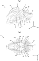
- FIG. 1 A front unit for a touring binding is generally designated 10.
- Figure 1 shows a perspective view of the front unit in a downhill configuration.
- a mounting surface of the front unit 10 pointing in the direction of a sliding board surface of a sliding board on which the front unit 10 is to be mounted defines a sliding board plane E.
- an X-axis running along a sliding board longitudinal axis L sliding board longitudinal direction or x-direction
- a Y-axis running orthogonal to the X-axis and parallel to the sliding board plane E sliding board transverse direction or y-direction
- a Z-axis running orthogonal to the sliding board plane E vertical direction or z-direction
- the front unit 10 can comprise a base 12, the underside of which defines the gliding board plane E.
- the base 12 can be in the form of a slide 12, which can be moved in the longitudinal direction of the gliding board by means of overlapping sections 14 on a base plate (not shown) in order to be able to adjust the length of the touring binding and thus adapt it to different sole lengths, wherein the base plate can be firmly mounted on the gliding board, for example by means of binding screws.
- the front unit 10 is between the Figure 1 shown departure configuration (see also Figure 2 ) and an ascent configuration (see e.g. Figure 4 ) and comprises a first holding device 20 and a second holding device 40.
- the first holding device 20 is designed to fix a front section of a gliding board shoe for a descent with the touring binding in the downhill configuration of the front unit 10.
- the first holding device 20 is adjustable between an active position and a passive position, wherein the first holding device 20 is set in the active position in the downhill configuration of the front unit 10 and is set in the passive position in the ascent configuration of the front unit 10.
- An essential idea of the invention is that the first holding device 20 is arranged closer to the sliding board plane E in the passive position than in the active position, i.e. in relation to a direction perpendicular to the sliding board plane E, it is arranged lower in the ascent configuration of the front unit 10 than in the descent configuration of the front unit 10.
- the first holding device 20 can comprise two clamping jaws 22a, 22b with contact surfaces 24a, 24b, which are designed to come into contact with a front section of the gliding board shoe in order to hold the gliding board shoe when the front unit 10 is set in the downhill configuration and the first holding device 20 is set in the active position.
- a clamping jaw 22a on the left in the direction of travel x can be pivotally mounted on the first holding device 20 about a pivot axis S2 that is substantially perpendicular to the gliding board plane E
- a clamping jaw 22b on the right in the direction of travel x can be pivotally mounted on the first holding device 20 about a pivot axis S3 that is substantially perpendicular to the gliding board plane E.
- the clamping jaws 22a, 22b can be pre-tensioned by at least one spring 30a, 30b such that they hold the sliding board shoe in place.
- the first holding device 20 in the present embodiment can be arranged further back in a direction of travel x parallel to the longitudinal axis L of the gliding board than the second holding device 40.
- the distances between the first holding device 20, the second holding device 40 and the heel unit (not shown) can in particular be set such that a heel section of the gliding board shoe can be coupled to the heel unit during a descent with the touring binding in the downhill configuration of the front unit 10 and is not disturbed by the heel unit during an ascent with the touring binding in the ascent configuration of the front unit 10.
- the second holding device 40 is designed to hold a toe section of the gliding board shoe for an ascent with the touring binding in the ascent configuration of the front unit 10 in such a way that the gliding board shoe can be pivoted about a rotation axis that is essentially parallel to the gliding board plane E and essentially perpendicular to the gliding board longitudinal axis L.
- the second holding device 40 can also be adjusted between an active position and a passive position, wherein it is set to the active position in the climbing configuration of the front unit 10 and is set to the passive position in the entry configuration of the front unit 10.
- Figure 5 shows a sectional view along the line AA in Figure 2 , ie the front unit 10 is shown in the downhill configuration
- Figure 6 shows a sectional view along the line BB in Figure 3
- ie the front unit 10 is shown in the entry-level configuration
- Figure 7 shows a sectional view along the line CC in Figure 4 , ie the front unit 10 is shown in the climbing position.
- the second holding device 40 can comprise two arms 42a, 42b pivotably mounted on the base 12.
- the two arms 42a, 42b can be mounted about axes of rotation S4, S5 that are essentially parallel to the sliding board longitudinal axis L, but alternatively it would also be conceivable for the two arms 42a, 42b to be pivotably mounted on the base 12 of the front unit 10 about axes of rotation that are essentially parallel to the sliding board plane E and essentially perpendicular to the sliding board longitudinal axis L, or for only one of the arms to be pivotably mounted and the other to be rigidly connected to the base 12 or formed integrally therewith.
- the pivotable mounting of the arms 42a, 42b can advantageously ensure that the two arms 42a, 42b of the second holding device 40 can be moved between a closed position and an open position in order to couple and uncouple the sliding board shoe.
- the closed position and the Opening position will be discussed later with reference to the Figures 8 to 10 described in more detail.
- An arm 42a of the two arms 42a, 42b that is on the left in the direction of travel x can have a left holding means 44a and an arm 42b of the two arms 42a, 42b that is on the right in the direction of travel x can have a right holding means 44b.
- These holding means 44a, 44b can in particular be projections 44a, 44b that are designed to engage in receptacles provided on the sliding board shoe.
- the holding means can be receptacles that are designed to be engaged by projections provided on the sliding board shoe.
- the holding means 44a, 44b can in particular be designed as bearing pins 44a, 44b with conically tapered tips that engage in corresponding, opposite lateral bearing recesses of a sliding board shoe.
- the front unit 10 can then be used in the ascent configuration when the gliding board shoe is held on the bearing pins, and in the descent configuration when the first holding device 20 immovably fixes the front section of the gliding board shoe.
- the bearing pins 44a, 44b in particular are then not in engagement with the bearing recesses of the gliding board shoe. Accordingly, the described holding means 44a, 44b can pivotally hold the gliding board shoe in the ascent configuration of the front unit 10.
- FIGs 5, 6 and 7 show sectional views of the front unit 10, where Figure 5 a sectional view along the line AA in Figure 2 shows, Figure 6 a sectional view along the line BB in Figure 3 shows and Figure 7 a sectional view along the line CC in Figure 4 shows. Accordingly, the front unit is in Figure 5 placed in the departure configuration, in Figure 6 placed in the entry-level configuration and in Figure 7 placed in the ascent configuration.
- the clamping jaw 22b can have a contact roller 26 and/or a retaining projection 25 in addition to the contact surface 24b or as a contact surface. This also applies equally to the clamping jaw 22a, which in the sectional views from the Figures 5 to 7 is not shown.
- the holding projection 25 can engage over or hold down a front section of the gliding board shoe in order to be able to hold the gliding board shoe even more securely in the downhill configuration.
- the contact roller is designed for contact with a front section of the gliding board shoe and supports a relative movement between the gliding board shoe and the clamping jaws during a release of the gliding board shoe in the event of a fall.
- the contact roller(s) 26 can thus ensure a reduction in friction in the contact area between the gliding board shoe and the front unit 10.
- the first holding device 20 can comprise a tread surface 27 for a sole section of the gliding board shoe on its side facing away from the gliding board.
- a user can move the first holding device 20 from the active position (see Figures 5 and 6 ) into the passive position (see Figure 7 ).
- the second holding device 40 can also be moved from the passive position ( Figure 6 ) to the active position ( Figure 7 ). This makes it possible for the user to simply step on the tread 27 of the first holding device 20 with the sole section of the sliding board shoe in order to engage the sliding board shoe and the second holding device 40.
- the first holding device 20 can be in the form of a housing 20 which can be pivoted about the axis of rotation S1 and in which a toggle lever system 62 described below is housed and on which the clamping jaws 22a, 22b are mounted so as to be pivotable about the axes of rotation S2, S3.
- the previously mentioned toggle lever system 62 can be part of a lever arrangement 60, 62 as a deflection mechanism 62, which further comprises an opening lever 60, which has an actuating section 61, in particular an exposed one.
- the opening lever 60 can in particular be pivotable about a lever axis H parallel to the sliding board plane E and perpendicular to the sliding board longitudinal axis L and can be adjusted by a pivoting movement about the lever axis H between a downhill position ( Figure 5 ), an entry-level position ( Figure 6 ) and a promotion position ( Figure 7 ).
- the front unit 10 By adjusting the opening lever 60 between the downhill position, the entry position and the ascent position by operating the operating section 61, the front unit 10 can be adjusted between the downhill configuration, the entry configuration and the ascent configuration.
- the opening lever 60 in the present embodiment is in Figure 5 in the departure configuration in a position close to the first holding device 20, in Figure 6 in the entry configuration in a position close to the gliding board and in Figure 7 in the ascent configuration in an upwardly projecting position, but other lever positions are also conceivable for the various configurations.
- the opening lever 60 can be pivoted at an angle of more than 90°, preferably more than 120° or even more than 150° about the pivot axis H in order to be able to provide the angular positions of the opening lever 60 described above.
- an adjusting movement of the opening lever 60 can be transmitted to the arms 42a, 42b of the second holding device 40 via a tensioning mechanism 50a, 50b, 52a, 52b described later, so that an opening angle of the arms 42a, 42b relative to one another is larger in the entry configuration than in the descent configuration and the ascent configuration (see also Figures 8 to 10 ).
- the adjusting lever 64 can for this purpose comprise a fork section 65 at the end, which engages around spring stops 52a, 52b of the tensioning mechanism. A more detailed operation will be explained later with reference to the Figures 8 to 10 described.
- the lever arrangement 60, 62 can also be designed to block the first holding device 20 in the active position in the down position of the opening lever 60 in order to stabilize it in the active position.
- the toggle lever system 62 can comprise a locking lever 66 which has a locking recess 68.
- the locking lever 66 can be designed as a locking section 66 of the opening lever 60 at an end of the opening lever 60 opposite the actuating section 61, in one piece with the opening lever 60.
- the locking lever 66 can be connected as a separate component rigidly to the opening lever 60 or immovably with respect to it.
- a locking projection 18 can be provided which is designed to be complementary to the locking recess 68 and which can engage with the locking recess 68 in the down configuration of the front unit 10 and the down position of the opening lever 60 in order to lock the first holding device 20 or to block it in its active position (see Figure 5 ).
- the deflection mechanism 62 can be configured such that the locking portion 68 can pivot in front of and behind the complementary locking portion 18 with respect to the direction x parallel to the sliding board longitudinal axis L, so that it can pivot in both directions beyond the locked position with the locking portion 18 on the base 12.
- the opening lever 60 is adjusted from the entry position to the departure position in such a way that the locking section 68 of the locking lever 66, starting from the ascent position, pivots over the complementary locking section 18 on the base 12.
- the adjustment movement of the opening lever 60 is, as previously mentioned, transmitted to the second holding device 40 in order to cause a movement of the arms 42a, 42b of the second holding device 40 relative to one another, in particular to change the opening angle of the arms 42a, 42b. This also changes the distance between the respective arms 42a, 42b provided holding means 44a, 44b.
- this distance is greater than a width of the sliding board shoe at the point to be coupled, so that the shoe can be guided between the holding means 44a, 44b.
- the distance between the holding means 44a, 44b is slightly smaller than the shoe width at the point to be coupled, so that the sliding board shoe is clamped.
- the distance between the holding means 44a, 44b can be set so small by the continued movement of the opening lever 60 beyond the locking position that the gliding board shoe cannot be coupled to the second holding device 40, but only to the first holding device 20, which is intended for the descent.
- a locking projection 18 complementary to the locking recess 68 can also be formed on the base 12, which can engage with the locking recess 68 in the ascending configuration of the front unit 10 and the ascending position of the opening lever 60 in order to lock the second holding device 40 or to block it in its active position (see Figure 7 ).
- a tread section 70 can also be seen, which has a tread plate 72 for a sole section of the sliding board shoe.
- the tread section 70 can be mounted on the base 12 or on the sliding board and can support the sole section of the sliding board shoe on the tread plate 72 at a predetermined height above the sliding board plane E.
- the tread plate 70 can be designed to move in a direction y substantially parallel to the sliding board plane E and substantially perpendicular to the sliding board longitudinal axis L when the first holding device 20 is released from the side.
- Mz release side release
- the tread plate 72 can be height-adjustable, for example by means of an adjusting screw 74, such that a distance between the tread plate 72 and the Gliding board level E is changeable.
- the front unit 10 can be adapted for different sole profiles or sole thicknesses.
- the height of the tread plate 72 above the gliding board level E can be adjusted in a relatively simple manner, for example by means of the adjusting screw 74, whereby the height of the tread plate 72 can be changed by rotating the screw 74.
- a crampon strap 90 for holding crampons can be attached, for example by means of screws, to the tread section 70 or to the sliding board itself.
- Figure 8 is a sectional view of the front unit 10 in the downhill configuration along the line DD in Figure 2
- Figure 9 is a sectional view of the front unit 10 in the ascent configuration along the line EE in Figure 4
- Figure 10 is a sectional view of the front unit 10 in the entry configuration along the line FF in Figure 3 .
- the second holding device 40 can comprise a tensioning mechanism 42a, 42b, 50a, 50b, 52a, 52b, which can be formed from the two arms 42a, 42b, for each arm 42a, 42b an elastic element in the form of compression springs 50a, 50b and for each spring 50a, 50b a spring stop.
- the tensioning mechanism 42a, 42b, 50a, 50b, 52a, 52b pre-tensions the second holding device 40 into the active position and/or into the passive position, wherein during the adjustment between the active position and the passive position, a dead point can be passed through in particular, so that the second holding device 40 is always either in the active position (see e.g. Figure 9 ) or in the passive position (see Figure 10 ) is prestressed.
- an opening angle of the arms 42a, 42b relative to each other in the entry configuration of the front unit 10 is larger than in the downhill configuration of the front unit 10 ( Figure 8 ) and the ascent configuration of the front unit 10 ( Figure 9 ).
- the compression springs 50a, 50b can be wound around mutually facing end sections of the arms 42a, 42b and press against the spring stops 52a, 52b at one spring end and press against a stepped section of the arms 42a, 42b at the respective opposite spring ends in order to pre-tension the second holding device 40 or the arms 42a, 42b.
- a dead point is passed through in which the clamping forces of the clamping mechanism are substantially cancelled out, so that the second holding device 40 can be pre-tensioned in both the passive position and the active position in each case.
- an end fork section 65 of the adjustment lever 64 of the toggle lever system 62 of the lever arrangement 60, 62 can engage around the spring stops 52a, 52b of the clamping mechanism of the second holding device 40.
- a pivoting movement of the opening lever 60 about the lever axis H can thereby be converted into a substantially vertical movement up and down of the spring stops 52a, 52b and thus into a pivoting movement of the arms 42a, 42b about the rotation axes S4, S5 in order to adjust the second holding device 40 between the active position and the passive position.
- Figure 11 is a sectional view of the front unit 10 in the downhill configuration along the line GG in Figure 2 .
- the first holding device 20 can comprise a release mechanism 22a, 22b, 30a, 30b, 32a, 32b, 34 with at least one elastic element 30a, 30b.
- two compression springs 30a, 30b can be provided as an elastic element, which press against spring guides 32a, 32b and whose spring preload can be changed, for example, by means of an adjusting screw 34 in order to be able to set a release force.
- the release mechanism 22a, 22b, 30a, 30b, 32a, 32b, 34 pre-tensions the first holding device 20 into a holding position by transferring the spring force of the springs 30a, 30b to the clamping jaws 22a, 22b such that they are pre-tensioned in one direction towards each other.
- the first holding device 20 holds the front section of the sliding board shoe by means of the clamping jaws 22a, 22b and when a predetermined release force acting on the contact surfaces 24a, 24b of the clamping jaws 22a, 22b is exceeded, which can be adjusted by changing the preload of the springs 30a, 30b, the first holding device 20 is brought into a release position in which the front section of the sliding board shoe is released, in particular by pivoting the contact surfaces 24a, 24b of the clamping jaws 22a, 22b away from each other about the rotation axes S2, S3.
- the release mechanism 22a, 22b, 30a, 30b, 32a, 32b, 34 can in particular be an Mz release mechanism.
Landscapes
- Braking Arrangements (AREA)
- Holders For Apparel And Elements Relating To Apparel (AREA)
Applications Claiming Priority (1)
| Application Number | Priority Date | Filing Date | Title |
|---|---|---|---|
| DE102022130901.0A DE102022130901A1 (de) | 2022-11-22 | 2022-11-22 | Vordereinheit mit absenkbarer Halteeinrichtung |
Publications (1)
| Publication Number | Publication Date |
|---|---|
| EP4374939A1 true EP4374939A1 (fr) | 2024-05-29 |
Family
ID=88923775
Family Applications (1)
| Application Number | Title | Priority Date | Filing Date |
|---|---|---|---|
| EP23211473.6A Pending EP4374939A1 (fr) | 2022-11-22 | 2023-11-22 | Butée avant avec mâchoire abaissable |
Country Status (3)
| Country | Link |
|---|---|
| US (1) | US20240165489A1 (fr) |
| EP (1) | EP4374939A1 (fr) |
| DE (1) | DE102022130901A1 (fr) |
Families Citing this family (1)
| Publication number | Priority date | Publication date | Assignee | Title |
|---|---|---|---|---|
| IT202200008585A1 (it) * | 2022-04-29 | 2023-10-29 | Atk Sports S R L | Puntale di attacco da sci alpino adattato per consentire anche la camminata in salita |
Citations (5)
| Publication number | Priority date | Publication date | Assignee | Title |
|---|---|---|---|---|
| EP2626116A1 (fr) | 2012-02-07 | 2013-08-14 | Fritz Barthel | Unité avant pour la fixation d'une planche de glisse |
| US9039031B2 (en) * | 2012-07-19 | 2015-05-26 | Salomon S.A.S. | Front retaining devices for a gliding board |
| US20200122016A1 (en) * | 2018-10-15 | 2020-04-23 | Marker Deutschland Gmbh | Front jaw |
| US11110338B1 (en) * | 2020-07-14 | 2021-09-07 | Thomas Alan Miller | Ski binding with heelless telemark coupling |
| EP4275770A1 (fr) | 2022-04-29 | 2023-11-15 | Atk Sports S.R.L. | Butée avant d'une fixation de ski adaptée pour également permettre la montée |
Family Cites Families (10)
| Publication number | Priority date | Publication date | Assignee | Title |
|---|---|---|---|---|
| DE102010029647A1 (de) * | 2010-06-02 | 2011-12-08 | Salewa Sport Ag | Tourenbindung |
| FR2966747B1 (fr) * | 2010-10-29 | 2013-01-11 | Salomon Sas | Fixation de securite pour la pratique du ski. |
| DE102012207959B4 (de) * | 2012-05-11 | 2020-11-12 | Fritz Barthel | Vordereinheit einer Gleitbrettbindung und Gleitbrettbindung |
| FR2997022B1 (fr) * | 2012-10-22 | 2015-01-02 | Salomon Sas | Butee avant d'un engin de glisse et engin de glisse equipe d'une telle fixation |
| EP2813268A1 (fr) * | 2013-06-12 | 2014-12-17 | Fritschi AG - Swiss Bindings | Automate avant |
| DE102014222052A1 (de) * | 2014-10-29 | 2016-05-04 | Fritz Barthel | Ferseneinheit für eine Gleitbrettbindung mit einer Bremsanordnung |
| EP3566754B1 (fr) * | 2018-05-08 | 2022-08-17 | Fritschi AG - Swiss Bindings | Butée avant de fixation de ski |
| DE102020116389B4 (de) * | 2020-06-22 | 2026-05-07 | Salewa Sport Ag | Vordereinheit für eine Tourenbindung mit Längspoitionierabschnitt |
| EP3851174A1 (fr) * | 2020-01-16 | 2021-07-21 | Fritschi AG - Swiss Bindings | Butée avant pour une fixation de ski |
| DE102020203278A1 (de) * | 2020-03-13 | 2021-09-16 | Salewa Sport Ag | Vordereinheit für eine Skibindung mit einer magnetischen Einstiegshilfe |
-
2022
- 2022-11-22 DE DE102022130901.0A patent/DE102022130901A1/de active Pending
-
2023
- 2023-11-22 EP EP23211473.6A patent/EP4374939A1/fr active Pending
- 2023-11-22 US US18/517,231 patent/US20240165489A1/en active Pending
Patent Citations (6)
| Publication number | Priority date | Publication date | Assignee | Title |
|---|---|---|---|---|
| EP2626116A1 (fr) | 2012-02-07 | 2013-08-14 | Fritz Barthel | Unité avant pour la fixation d'une planche de glisse |
| US9039031B2 (en) * | 2012-07-19 | 2015-05-26 | Salomon S.A.S. | Front retaining devices for a gliding board |
| US20200122016A1 (en) * | 2018-10-15 | 2020-04-23 | Marker Deutschland Gmbh | Front jaw |
| US11110338B1 (en) * | 2020-07-14 | 2021-09-07 | Thomas Alan Miller | Ski binding with heelless telemark coupling |
| EP4275770A1 (fr) | 2022-04-29 | 2023-11-15 | Atk Sports S.R.L. | Butée avant d'une fixation de ski adaptée pour également permettre la montée |
| EP4275770B1 (fr) * | 2022-04-29 | 2025-01-15 | Atk Sports S.R.L. | Butée avant d'une fixation de ski adaptée pour également permettre la montée |
Also Published As
| Publication number | Publication date |
|---|---|
| DE102022130901A1 (de) | 2024-05-23 |
| US20240165489A1 (en) | 2024-05-23 |
Similar Documents
| Publication | Publication Date | Title |
|---|---|---|
| DE102012201816B4 (de) | Vordereinheit für eine Gleitbrettbindung mit ersten und zweiten Eingriffsmitteln | |
| EP2762209B1 (fr) | Talonnière avec levier auxiliaire | |
| EP2666525B1 (fr) | Talonnière avec cale de montée et ensemble stop-ski | |
| EP2420306B1 (fr) | Elément de couplage pour une chaussure de ski et chaussure de ski | |
| DE9421380U1 (de) | Snowboardbindung | |
| EP3928842B1 (fr) | Unité avant pour une fixation de randonnée | |
| EP2662121A2 (fr) | Butée avant d'une fixation de planche de glisse et fixation de planche de glisse | |
| EP2452731A1 (fr) | Fixation de randonnée dotée d'un mécanisme de déclenchement et d'un mécanisme de verrouillage | |
| EP4374939A1 (fr) | Butée avant avec mâchoire abaissable | |
| EP3639901B1 (fr) | Verrouillage de la mâchoire avant d'une fixation de randonnee a ski à l'aide d'une chaussure de ski | |
| EP3878528B1 (fr) | Unité avant pour une fixation de ski doté d'une aide au chaussage | |
| EP3848099B1 (fr) | Talon pourvu de cale de montée pour une fixation de randonnée | |
| EP3906980B1 (fr) | Talonnière pour une fixation de ski | |
| EP2821113B1 (fr) | Butée avant dotée d'un moyen de chaussement | |
| EP4452430B1 (fr) | Système de fixation pour une fixation de ski de randonnée | |
| AT522136A2 (de) | Vordereinheit für eine Gleitbrettbindung | |
| DE102012214002B4 (de) | Touring-Ferse mit Hilfshebel | |
| EP2821114B1 (fr) | Système de fixation de sécurité | |
| EP0113415B1 (fr) | Fixation de sécurité pour ski de fond | |
| EP3714952A1 (fr) | Dispositif de freinage | |
| DE102020203278A1 (de) | Vordereinheit für eine Skibindung mit einer magnetischen Einstiegshilfe | |
| AT410176B (de) | Bindungskonstruktion | |
| EP3851174A1 (fr) | Butée avant pour une fixation de ski | |
| EP3878527B1 (fr) | Unité avant pour une fixation de ski présentant une butée d'ouverture définie sur la platine de base | |
| DE102024129167A1 (de) | Ferseneinheit für eine Tourenbindung |
Legal Events
| Date | Code | Title | Description |
|---|---|---|---|
| PUAI | Public reference made under article 153(3) epc to a published international application that has entered the european phase |
Free format text: ORIGINAL CODE: 0009012 |
|
| STAA | Information on the status of an ep patent application or granted ep patent |
Free format text: STATUS: THE APPLICATION HAS BEEN PUBLISHED |
|
| AK | Designated contracting states |
Kind code of ref document: A1 Designated state(s): AL AT BE BG CH CY CZ DE DK EE ES FI FR GB GR HR HU IE IS IT LI LT LU LV MC ME MK MT NL NO PL PT RO RS SE SI SK SM TR |
|
| STAA | Information on the status of an ep patent application or granted ep patent |
Free format text: STATUS: REQUEST FOR EXAMINATION WAS MADE |
|
| TPAC | Observations filed by third parties |
Free format text: ORIGINAL CODE: EPIDOSNTIPA |
|
| 17P | Request for examination filed |
Effective date: 20241126 |
|
| RBV | Designated contracting states (corrected) |
Designated state(s): AL AT BE BG CH CY CZ DE DK EE ES FI FR GB GR HR HU IE IS IT LI LT LU LV MC ME MK MT NL NO PL PT RO RS SE SI SK SM TR |
|
| STAA | Information on the status of an ep patent application or granted ep patent |
Free format text: STATUS: EXAMINATION IS IN PROGRESS |
|
| 17Q | First examination report despatched |
Effective date: 20250929 |