EP3848665A1 - Bloc de connexion d'échangeur de chaleur, ensemble échangeur de chaleur doté dudit bloc de connexion et procédé de fabrication dudit ensemble échangeur de chaleur - Google Patents
Bloc de connexion d'échangeur de chaleur, ensemble échangeur de chaleur doté dudit bloc de connexion et procédé de fabrication dudit ensemble échangeur de chaleur Download PDFInfo
- Publication number
- EP3848665A1 EP3848665A1 EP20461501.7A EP20461501A EP3848665A1 EP 3848665 A1 EP3848665 A1 EP 3848665A1 EP 20461501 A EP20461501 A EP 20461501A EP 3848665 A1 EP3848665 A1 EP 3848665A1
- Authority
- EP
- European Patent Office
- Prior art keywords
- connection block
- heat exchanger
- opening
- brazing
- tube
- Prior art date
- Legal status (The legal status is an assumption and is not a legal conclusion. Google has not performed a legal analysis and makes no representation as to the accuracy of the status listed.)
- Withdrawn
Links
Images

Classifications
-
- F—MECHANICAL ENGINEERING; LIGHTING; HEATING; WEAPONS; BLASTING
- F28—HEAT EXCHANGE IN GENERAL
- F28F—DETAILS OF HEAT-EXCHANGE AND HEAT-TRANSFER APPARATUS, OF GENERAL APPLICATION
- F28F9/00—Casings; Header boxes; Auxiliary supports for elements; Auxiliary members within casings
- F28F9/02—Header boxes; End plates
- F28F9/0246—Arrangements for connecting header boxes with flow lines
- F28F9/0251—Massive connectors, e.g. blocks; Plate-like connectors
-
- B—PERFORMING OPERATIONS; TRANSPORTING
- B23—MACHINE TOOLS; METAL-WORKING NOT OTHERWISE PROVIDED FOR
- B23K—SOLDERING OR UNSOLDERING; WELDING; CLADDING OR PLATING BY SOLDERING OR WELDING; CUTTING BY APPLYING HEAT LOCALLY, e.g. FLAME CUTTING; WORKING BY LASER BEAM
- B23K1/00—Soldering, e.g. brazing, or unsoldering
- B23K1/0008—Soldering, e.g. brazing, or unsoldering specially adapted for particular articles or work
- B23K1/0012—Brazing of heat exchangers
-
- B—PERFORMING OPERATIONS; TRANSPORTING
- B23—MACHINE TOOLS; METAL-WORKING NOT OTHERWISE PROVIDED FOR
- B23K—SOLDERING OR UNSOLDERING; WELDING; CLADDING OR PLATING BY SOLDERING OR WELDING; CUTTING BY APPLYING HEAT LOCALLY, e.g. FLAME CUTTING; WORKING BY LASER BEAM
- B23K1/00—Soldering, e.g. brazing, or unsoldering
- B23K1/008—Soldering within a furnace
-
- B—PERFORMING OPERATIONS; TRANSPORTING
- B23—MACHINE TOOLS; METAL-WORKING NOT OTHERWISE PROVIDED FOR
- B23K—SOLDERING OR UNSOLDERING; WELDING; CLADDING OR PLATING BY SOLDERING OR WELDING; CUTTING BY APPLYING HEAT LOCALLY, e.g. FLAME CUTTING; WORKING BY LASER BEAM
- B23K1/00—Soldering, e.g. brazing, or unsoldering
- B23K1/20—Preliminary treatment of work or areas to be soldered, e.g. in respect of a galvanic coating
-
- B—PERFORMING OPERATIONS; TRANSPORTING
- B23—MACHINE TOOLS; METAL-WORKING NOT OTHERWISE PROVIDED FOR
- B23K—SOLDERING OR UNSOLDERING; WELDING; CLADDING OR PLATING BY SOLDERING OR WELDING; CUTTING BY APPLYING HEAT LOCALLY, e.g. FLAME CUTTING; WORKING BY LASER BEAM
- B23K3/00—Tools, devices or special appurtenances for soldering, e.g. brazing, or unsoldering, not specially adapted for particular methods
- B23K3/08—Auxiliary devices therefor
-
- B—PERFORMING OPERATIONS; TRANSPORTING
- B23—MACHINE TOOLS; METAL-WORKING NOT OTHERWISE PROVIDED FOR
- B23K—SOLDERING OR UNSOLDERING; WELDING; CLADDING OR PLATING BY SOLDERING OR WELDING; CUTTING BY APPLYING HEAT LOCALLY, e.g. FLAME CUTTING; WORKING BY LASER BEAM
- B23K37/00—Auxiliary devices or processes, not specially adapted for a procedure covered by only one of the other main groups of this subclass
-
- B—PERFORMING OPERATIONS; TRANSPORTING
- B23—MACHINE TOOLS; METAL-WORKING NOT OTHERWISE PROVIDED FOR
- B23K—SOLDERING OR UNSOLDERING; WELDING; CLADDING OR PLATING BY SOLDERING OR WELDING; CUTTING BY APPLYING HEAT LOCALLY, e.g. FLAME CUTTING; WORKING BY LASER BEAM
- B23K37/00—Auxiliary devices or processes, not specially adapted for a procedure covered by only one of the other main groups of this subclass
- B23K37/04—Auxiliary devices or processes, not specially adapted for a procedure covered by only one of the other main groups of this subclass for holding or positioning work
-
- F—MECHANICAL ENGINEERING; LIGHTING; HEATING; WEAPONS; BLASTING
- F28—HEAT EXCHANGE IN GENERAL
- F28F—DETAILS OF HEAT-EXCHANGE AND HEAT-TRANSFER APPARATUS, OF GENERAL APPLICATION
- F28F9/00—Casings; Header boxes; Auxiliary supports for elements; Auxiliary members within casings
- F28F9/02—Header boxes; End plates
- F28F9/0246—Arrangements for connecting header boxes with flow lines
- F28F9/0251—Massive connectors, e.g. blocks; Plate-like connectors
- F28F9/0253—Massive connectors, e.g. blocks; Plate-like connectors with multiple channels, e.g. with combined inflow and outflow channels
-
- B—PERFORMING OPERATIONS; TRANSPORTING
- B23—MACHINE TOOLS; METAL-WORKING NOT OTHERWISE PROVIDED FOR
- B23K—SOLDERING OR UNSOLDERING; WELDING; CLADDING OR PLATING BY SOLDERING OR WELDING; CUTTING BY APPLYING HEAT LOCALLY, e.g. FLAME CUTTING; WORKING BY LASER BEAM
- B23K2101/00—Articles made by soldering, welding or cutting
- B23K2101/04—Tubular or hollow articles
- B23K2101/14—Heat exchangers
-
- F—MECHANICAL ENGINEERING; LIGHTING; HEATING; WEAPONS; BLASTING
- F28—HEAT EXCHANGE IN GENERAL
- F28F—DETAILS OF HEAT-EXCHANGE AND HEAT-TRANSFER APPARATUS, OF GENERAL APPLICATION
- F28F2275/00—Fastening; Joining
- F28F2275/04—Fastening; Joining by brazing
- F28F2275/045—Fastening; Joining by brazing with particular processing steps, e.g. by allowing displacement of parts during brazing or by using a reservoir for storing brazing material
-
- F—MECHANICAL ENGINEERING; LIGHTING; HEATING; WEAPONS; BLASTING
- F28—HEAT EXCHANGE IN GENERAL
- F28F—DETAILS OF HEAT-EXCHANGE AND HEAT-TRANSFER APPARATUS, OF GENERAL APPLICATION
- F28F2280/00—Mounting arrangements; Arrangements for facilitating assembling or disassembling of heat exchanger parts
- F28F2280/04—Means for preventing wrong assembling of parts
Definitions
- the invention relates to a heat exchanger connection block. Further, it relates to a heat exchanger manifold comprising said connection block and a heat exchanger comprising said connection block.
- the components may be connected to each other through various means and processes.
- One of them is brazing, in which a component made of material with melting temperature lower than in other components melts and then solidifies to connect said components.
- brazing ring which is a circular element constituted by a brazing material.
- Such brazing ring may for example be put around a circular opening, into which subsequently a cylindrical element is introduced. The whole assembly is then put into a brazing furnace and subjected to a temperature, which will cause melting of the brazing material but not of the components. After cooling of the assembly, the components are effectively brazed and immobilized with respect to each other.
- brazing ring will not for some reason be introduced properly into a desired place. It may also happen that the brazing ring will not be introduced at all. This is highly undesirable, as in such case the connection will not be performed properly and the components will not be sealingly connected. The result of such occurrence may be leaks of the heat exchange fluid or even falling out of the element intended to be connected, which leads to quality issues.
- the object of the invention is, among others, a heat exchanger connection block comprising an opening for a tube and a see-through channel tangent to the opening, the opening being adapted to receive a brazing ring, wherein the connection block is adapted to accommodate at least part of the brazing ring within the see-through channel.
- the see-through channel is exposed from the face of the opening.
- the see-through channel is covered with respect to the face of the opening.
- a tube is inserted into the opening.
- the tube comprises a collar adjacent to the opening.
- a brazing ring is received in the opening and accommodated at least partly within the see-through channel.
- the collar is brazed to the connection block and to the see-through channel.
- the opening comprises a stop portion for a tube, configured to enable only partial insertion of the tube.
- Another object of the invention is a manifold comprising a connection block as described above.
- Another object of the invention is a heat exchanger comprising a connection block as described above.
- Another object of the invention is a method of manufacturing of a heat exchanger assembly, comprising steps of: providing a heat exchanger assembly with a connection block and a tube introduced into the connection block; aligning the heat exchanger assembly in a position for determining of presence of a brazing ring between the connection block and the tube; determining presence of the brazing ring by means of a sensor and selecting between sending the heat exchanger assembly for brazing process in case of presence of the brazing ring and preventing the heat exchanger assembly from being sent for brazing process in case of absence of the brazing ring.
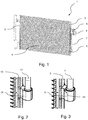
- Fig. 1 shows a heat exchanger 1 comprising a connection block 6 according to the invention.
- the heat exchanger 1 is a condenser.
- the invention may however apply to different heat exchangers in which a cylindrical element is connected to a connection block by use of a brazing ring.
- the heat exchanger 1 comprises manifolds 2, 3 connected fluidly to each other by means of heat exchange tubes 4.
- the heat exchanger 1 further comprises connection blocks 5, 6 serving as an inlet and outlet of the heat exchanger 1.
- the connection blocks 5, 6 are attached to manifold 3 to enable flow to and from heat exchange tubes 4.
- the heat exchange blocks 5, 6 may be located each on a separate manifold 2, 3 or on a common manifold 2, 3, depending on flow configuration within the heat exchanger 1.
- Connection block 6 is further connected with a so-called jumper line. In this case, this is a tube 7 introduced into the block 6.
- the function of the tube 7 is to convey the heat exchange fluid to or from a differently positioned place with respect to the connection block 6.
- the reason for such arrangement may be a requirement for placement of a socket 8, serving as a connection point for heat exchange conduits of the system to and/or from the heat exchanger, in a place different from the position of the inlet/outlet connection block resulting from preferred fluid flow arrangement within the heat exchanger.
- a socket 8 serving as a connection point for heat exchange conduits of the system to and/or from the heat exchanger, in a place different from the position of the inlet/outlet connection block resulting from preferred fluid flow arrangement within the heat exchanger.
- Fig. 2 shows a prior art connection block 16 in a perspective view, in an application analogous to the one from Fig. 1 .
- a connection block 16 is connected to manifold 13, while a tube 17 is connected to the connection block 16, so that a heat exchange fluid can be relayed between these elements.
- the connection block 16 is uniform in the region in which the tube 17 is introduced therein.
- the tube 17 may be connected to connection block 16 by use of a brazing ring.
- connection block 6 shows a connection block according to the invention in a perspective view.
- the connection block 6 is connected to the manifold 3, while tube 7 is connected to the connection block 6 so that fluid communication between them is enabled.
- the connection block 6 further comprises a see-through channel 22, which enables external, for example visual, determination of brazing ring presence, as will be explained below.
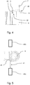
- Fig. 4 shows a connection block 6 according to the invention in a side view with a brazing ring 30 in place.
- the connection block 6 comprises an opening 20 in which tube 7 is insertable, wherein the connection block 6 further comprises an opening collar 21 to protect part of the connection.
- the opening 20 is adapted to receive a brazing ring 30.
- An example of such adaptation is a dedicated annular groove intended for placement of a brazing ring so that during brazing the brazing material will join the tube 7 with the connection block 6.
- the see-though channel 22 is configured so that when the brazing ring 30 is not received in the opening 20, it is possible for a see through the channel 22 from one side of the connection block 6 to another.
- the see-through channel 22 may be exposed from the face of the opening 20. This may allow to facilitate insertion of the brazing ring 30.
- the see-through channel 22 may be covered with respect to the face of the opening 20. In other words, the face of the opening 20 may be uniform when viewed along the axis of the opening 20, without any open channel being tangent to it.
- Covered see-through channel 22 may prevent the brazing ring 30 from falling out before insertion of tube 7. It may also protect the connection after brazing process.
- the opening 20 may comprise a stop portion for the tube 7, configured to enable only partial insertion of the tube 7 into the connection block 6.
- the stop portion may be a section of the opening 20 deeper within the connection block 6, with a reduced diameter so that the tube 7 will stop on it after insertion.
- the tube 7 may comprise a collar 9 adjacent to the opening 20, for facilitating brazing connection with the connection block.
- Fig. 5 shows checking of presence of a brazing ring 30 within the block 6 in case of brazing ring 30 presence.
- the check can be performed by means of sensors, for example by a system comprising an emitter 40a and a receiver 40b.
- the laser beam 41 sent by the emitter 40a is stopped by the brazing ring 30 within the see-through channel 22, and is prevented from reaching the receiver 40b. In such case, the presence of the brazing ring 30 can be confirmed and the heat exchanger can be sent for brazing process.
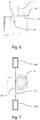
- Fig. 6 shows a connection block 6 according to the invention in a side view with no brazing ring 30 in place.
- the see-through channel 22 is unobstructed by the brazing ring 30.
- Fig. 7 shows checking of presence of a brazing ring 30 within the block 6 in case of brazing ring 30 absence.
- the laser beam 41 sent by an emitter 40a is not stopped by the brazing ring 30 within the see-through channel 22, therefore it can reach the receiver 40b. In such case, the absence of the brazing ring 30 can be confirmed and the heat exchanger can be prevented from being sent for brazing process.
- Fig. 8 shows a method of manufacturing of a heat exchanger according to the invention.
- a heat exchanger assembly with a connection block 6 and a tube 7 introduced into the connection block 6 is provided in step 101.
- the heat exchanger assembly is aligned in a position for determining of presence of a brazing ring 30 between the connection block 6 and the tube 7 in step 102.
- presence of the brazing ring is determined, by a human worker or automatically, for example by means of sensor means. Based on the results of the determination, the heat exchanger assembly can be sent for brazing process in case of presence of the brazing ring in step 104 or prevented from being sent for brazing process in case of absence of the brazing ring 30 in step 105.
Landscapes
- Engineering & Computer Science (AREA)
- Mechanical Engineering (AREA)
- Physics & Mathematics (AREA)
- Thermal Sciences (AREA)
- General Engineering & Computer Science (AREA)
- Optics & Photonics (AREA)
- Heat-Exchange Devices With Radiators And Conduit Assemblies (AREA)
- Details Of Heat-Exchange And Heat-Transfer (AREA)
Priority Applications (1)
| Application Number | Priority Date | Filing Date | Title |
|---|---|---|---|
| EP20461501.7A EP3848665A1 (fr) | 2020-01-08 | 2020-01-08 | Bloc de connexion d'échangeur de chaleur, ensemble échangeur de chaleur doté dudit bloc de connexion et procédé de fabrication dudit ensemble échangeur de chaleur |
Applications Claiming Priority (1)
| Application Number | Priority Date | Filing Date | Title |
|---|---|---|---|
| EP20461501.7A EP3848665A1 (fr) | 2020-01-08 | 2020-01-08 | Bloc de connexion d'échangeur de chaleur, ensemble échangeur de chaleur doté dudit bloc de connexion et procédé de fabrication dudit ensemble échangeur de chaleur |
Publications (1)
| Publication Number | Publication Date |
|---|---|
| EP3848665A1 true EP3848665A1 (fr) | 2021-07-14 |
Family
ID=69156346
Family Applications (1)
| Application Number | Title | Priority Date | Filing Date |
|---|---|---|---|
| EP20461501.7A Withdrawn EP3848665A1 (fr) | 2020-01-08 | 2020-01-08 | Bloc de connexion d'échangeur de chaleur, ensemble échangeur de chaleur doté dudit bloc de connexion et procédé de fabrication dudit ensemble échangeur de chaleur |
Country Status (1)
| Country | Link |
|---|---|
| EP (1) | EP3848665A1 (fr) |
Citations (3)
| Publication number | Priority date | Publication date | Assignee | Title |
|---|---|---|---|---|
| WO1999057501A1 (fr) * | 1998-05-05 | 1999-11-11 | Norsk Hydro Asa | Bloc collecteur pour echangeur de chaleur presentant une meilleure aptitude au brasage |
| EP1496329A2 (fr) * | 2003-07-03 | 2005-01-12 | Delphi Technologies, Inc. | Echangeur de chaleur et sa méthode de fabrication |
| US20080129043A1 (en) * | 2006-11-30 | 2008-06-05 | Matthew Holt | Conduit to component fitting having a leak detection mechanism |
-
2020
- 2020-01-08 EP EP20461501.7A patent/EP3848665A1/fr not_active Withdrawn
Patent Citations (3)
| Publication number | Priority date | Publication date | Assignee | Title |
|---|---|---|---|---|
| WO1999057501A1 (fr) * | 1998-05-05 | 1999-11-11 | Norsk Hydro Asa | Bloc collecteur pour echangeur de chaleur presentant une meilleure aptitude au brasage |
| EP1496329A2 (fr) * | 2003-07-03 | 2005-01-12 | Delphi Technologies, Inc. | Echangeur de chaleur et sa méthode de fabrication |
| US20080129043A1 (en) * | 2006-11-30 | 2008-06-05 | Matthew Holt | Conduit to component fitting having a leak detection mechanism |
Similar Documents
| Publication | Publication Date | Title |
|---|---|---|
| CN101482346B (zh) | 分配器管道子组件 | |
| US7021670B2 (en) | Joint for double pipe and brazing method thereof | |
| TWI619920B (zh) | 板式熱交換器及在該板式熱交換器中提供通孔的方法 | |
| US5098006A (en) | Header jig | |
| US7226089B2 (en) | Jacketed pipe flange | |
| EP3246609B1 (fr) | Tuyau caréné | |
| US11598470B2 (en) | Dual layer hose with venting port | |
| US5071174A (en) | Brazed tubing connector construction and method | |
| US9920864B2 (en) | Connecting device, and corresponding thermal exchanger, particularly for a motor vehicle | |
| US4653291A (en) | Coupling mechanism for an expansion device in a refrigeration system | |
| BR0208378B1 (pt) | Método de instalação de um oleoduto no fundo do mar e elemento anular para encaixe na extremidade de um primeiro tubo externo de um oleoduto | |
| US5398981A (en) | Self-centering, self-seating, double-sealing, intereference fit tube joint | |
| CN1739000B (zh) | 具有连接集流管的连接法兰的热交换器 | |
| CN109073490B (zh) | 用于制造压力传递系统的方法 | |
| US20230003331A1 (en) | Assembly for Engaging the Interior of a Pipe | |
| US6648375B1 (en) | Pilot insert seal for a tube fitting | |
| US20040256854A1 (en) | Fitting for fluid conveyance | |
| US20250164047A1 (en) | Piping system comprising pipe block | |
| EP2125152A1 (fr) | Dispositif de contrôle d'émissions | |
| US7077194B2 (en) | Brazed condenser jumper tube | |
| SE513540C2 (sv) | Ett förfarande för att framställa en plattvärmeväxlare samt en plattvärmeväxlare | |
| CN103192243A (zh) | 形成用于热交换器的连接部分的方法 | |
| CN113108639A (zh) | 连接器与同轴管状热交换器的密封连接 | |
| ITRM20000488A1 (it) | Apparecchio per il drenaggio di un fluido da un recipiente a pressione e procedimento per il suo impiego. | |
| EP3680594B1 (fr) | Connexion de fluide brasée pour un échangeur de chaleur |
Legal Events
| Date | Code | Title | Description |
|---|---|---|---|
| PUAI | Public reference made under article 153(3) epc to a published international application that has entered the european phase |
Free format text: ORIGINAL CODE: 0009012 |
|
| STAA | Information on the status of an ep patent application or granted ep patent |
Free format text: STATUS: THE APPLICATION HAS BEEN PUBLISHED |
|
| AK | Designated contracting states |
Kind code of ref document: A1 Designated state(s): AL AT BE BG CH CY CZ DE DK EE ES FI FR GB GR HR HU IE IS IT LI LT LU LV MC MK MT NL NO PL PT RO RS SE SI SK SM TR |
|
| STAA | Information on the status of an ep patent application or granted ep patent |
Free format text: STATUS: THE APPLICATION IS DEEMED TO BE WITHDRAWN |
|
| 18D | Application deemed to be withdrawn |
Effective date: 20220115 |