EP3848770A1 - Procédé de fonctionnement d'un système pourvu de deux appareils de traitement du sol autonome et système destiné à la mise en uvre d'un tel procédé - Google Patents
Procédé de fonctionnement d'un système pourvu de deux appareils de traitement du sol autonome et système destiné à la mise en uvre d'un tel procédé Download PDFInfo
- Publication number
- EP3848770A1 EP3848770A1 EP21150448.5A EP21150448A EP3848770A1 EP 3848770 A1 EP3848770 A1 EP 3848770A1 EP 21150448 A EP21150448 A EP 21150448A EP 3848770 A1 EP3848770 A1 EP 3848770A1
- Authority
- EP
- European Patent Office
- Prior art keywords
- soil cultivation
- cultivation device
- soil
- map
- activity
- Prior art date
- Legal status (The legal status is an assumption and is not a legal conclusion. Google has not performed a legal analysis and makes no representation as to the accuracy of the status listed.)
- Granted
Links
Images



Classifications
-
- G—PHYSICS
- G05—CONTROLLING; REGULATING
- G05D—SYSTEMS FOR CONTROLLING OR REGULATING NON-ELECTRIC VARIABLES
- G05D1/00—Control of position, course, altitude or attitude of land, water, air or space vehicles, e.g. using automatic pilots
- G05D1/60—Intended control result
- G05D1/69—Coordinated control of the position or course of two or more vehicles
- G05D1/692—Coordinated control of the position or course of two or more vehicles involving a plurality of disparate vehicles
-
- G—PHYSICS
- G05—CONTROLLING; REGULATING
- G05D—SYSTEMS FOR CONTROLLING OR REGULATING NON-ELECTRIC VARIABLES
- G05D1/00—Control of position, course, altitude or attitude of land, water, air or space vehicles, e.g. using automatic pilots
- G05D1/02—Control of position or course in two dimensions
- G05D1/021—Control of position or course in two dimensions specially adapted to land vehicles
- G05D1/0268—Control of position or course in two dimensions specially adapted to land vehicles using internal positioning means
- G05D1/0274—Control of position or course in two dimensions specially adapted to land vehicles using internal positioning means using mapping information stored in a memory device
-
- A—HUMAN NECESSITIES
- A47—FURNITURE; DOMESTIC ARTICLES OR APPLIANCES; COFFEE MILLS; SPICE MILLS; SUCTION CLEANERS IN GENERAL
- A47L—DOMESTIC WASHING OR CLEANING; SUCTION CLEANERS IN GENERAL
- A47L9/00—Details or accessories of suction cleaners, e.g. mechanical means for controlling the suction or for effecting pulsating action; Storing devices specially adapted to suction cleaners or parts thereof; Carrying-vehicles specially adapted for suction cleaners
- A47L9/28—Installation of the electric equipment, e.g. adaptation or attachment to the suction cleaner; Controlling suction cleaners by electric means
-
- A—HUMAN NECESSITIES
- A47—FURNITURE; DOMESTIC ARTICLES OR APPLIANCES; COFFEE MILLS; SPICE MILLS; SUCTION CLEANERS IN GENERAL
- A47L—DOMESTIC WASHING OR CLEANING; SUCTION CLEANERS IN GENERAL
- A47L11/00—Machines for cleaning floors, carpets, furniture, walls, or wall coverings
- A47L11/40—Parts or details of machines not provided for in groups A47L11/02 - A47L11/38, or not restricted to one of these groups, e.g. handles, arrangements of switches, skirts, buffers, levers
- A47L11/4061—Steering means; Means for avoiding obstacles; Details related to the place where the driver is accommodated
-
- G—PHYSICS
- G01—MEASURING; TESTING
- G01C—MEASURING DISTANCES, LEVELS OR BEARINGS; SURVEYING; NAVIGATION; GYROSCOPIC INSTRUMENTS; PHOTOGRAMMETRY OR VIDEOGRAMMETRY
- G01C21/00—Navigation; Navigational instruments not provided for in groups G01C1/00 - G01C19/00
- G01C21/005—Navigation; Navigational instruments not provided for in groups G01C1/00 - G01C19/00 with correlation of navigation data from several sources, e.g. map or contour matching
-
- G—PHYSICS
- G01—MEASURING; TESTING
- G01C—MEASURING DISTANCES, LEVELS OR BEARINGS; SURVEYING; NAVIGATION; GYROSCOPIC INSTRUMENTS; PHOTOGRAMMETRY OR VIDEOGRAMMETRY
- G01C21/00—Navigation; Navigational instruments not provided for in groups G01C1/00 - G01C19/00
- G01C21/20—Instruments for performing navigational calculations
-
- G—PHYSICS
- G05—CONTROLLING; REGULATING
- G05D—SYSTEMS FOR CONTROLLING OR REGULATING NON-ELECTRIC VARIABLES
- G05D1/00—Control of position, course, altitude or attitude of land, water, air or space vehicles, e.g. using automatic pilots
- G05D1/02—Control of position or course in two dimensions
- G05D1/021—Control of position or course in two dimensions specially adapted to land vehicles
- G05D1/0287—Control of position or course in two dimensions specially adapted to land vehicles involving a plurality of land vehicles, e.g. fleet or convoy travelling
- G05D1/0291—Fleet control
-
- G—PHYSICS
- G05—CONTROLLING; REGULATING
- G05D—SYSTEMS FOR CONTROLLING OR REGULATING NON-ELECTRIC VARIABLES
- G05D1/00—Control of position, course, altitude or attitude of land, water, air or space vehicles, e.g. using automatic pilots
- G05D1/20—Control system inputs
- G05D1/24—Arrangements for determining position or orientation
- G05D1/246—Arrangements for determining position or orientation using environment maps, e.g. simultaneous localisation and mapping [SLAM]
-
- G—PHYSICS
- G05—CONTROLLING; REGULATING
- G05D—SYSTEMS FOR CONTROLLING OR REGULATING NON-ELECTRIC VARIABLES
- G05D1/00—Control of position, course, altitude or attitude of land, water, air or space vehicles, e.g. using automatic pilots
- G05D1/20—Control system inputs
- G05D1/24—Arrangements for determining position or orientation
- G05D1/247—Arrangements for determining position or orientation using signals provided by artificial sources external to the vehicle, e.g. navigation beacons
- G05D1/249—Arrangements for determining position or orientation using signals provided by artificial sources external to the vehicle, e.g. navigation beacons from positioning sensors located off-board the vehicle, e.g. from cameras
-
- G—PHYSICS
- G05—CONTROLLING; REGULATING
- G05D—SYSTEMS FOR CONTROLLING OR REGULATING NON-ELECTRIC VARIABLES
- G05D1/00—Control of position, course, altitude or attitude of land, water, air or space vehicles, e.g. using automatic pilots
- G05D1/60—Intended control result
- G05D1/69—Coordinated control of the position or course of two or more vehicles
-
- A—HUMAN NECESSITIES
- A47—FURNITURE; DOMESTIC ARTICLES OR APPLIANCES; COFFEE MILLS; SPICE MILLS; SUCTION CLEANERS IN GENERAL
- A47L—DOMESTIC WASHING OR CLEANING; SUCTION CLEANERS IN GENERAL
- A47L2201/00—Robotic cleaning machines, i.e. with automatic control of the travelling movement or the cleaning operation
-
- A—HUMAN NECESSITIES
- A47—FURNITURE; DOMESTIC ARTICLES OR APPLIANCES; COFFEE MILLS; SPICE MILLS; SUCTION CLEANERS IN GENERAL
- A47L—DOMESTIC WASHING OR CLEANING; SUCTION CLEANERS IN GENERAL
- A47L2201/00—Robotic cleaning machines, i.e. with automatic control of the travelling movement or the cleaning operation
- A47L2201/04—Automatic control of the travelling movement; Automatic obstacle detection
Definitions
- the invention relates to a method for operating a system with an automatically moving first soil cultivation device and an automatically moving second soil cultivation device, the first soil cultivation device detecting environmental features of the surroundings of the first soil cultivation device, the first soil cultivation device or one of the first soil cultivation device and the second soil cultivation device in common associated computing device creates a first map of the surroundings based on the detected environmental features, and wherein the first soil cultivation device furthermore detects the second soil cultivation device and the position of the second soil cultivation device is then stored within the created first environmental map.
- the invention also relates to a system with a first soil cultivation device and a second soil cultivation device for carrying out a method of the aforementioned type.
- the soil cultivation devices can be, for example, soil cultivation robots such as cleaning robots, polishing robots, robotic lawn mowers or the like.
- At least One of the soil cultivation devices has a navigation and self-localization device which is suitable for creating a map of the surroundings and for locating and moving around on the basis of this map of the surroundings.
- the soil cultivation devices can access a common map of the surroundings, which is stored in an external storage device.
- the patent specification US 6,374,155 B1 further discloses a system with a plurality of robots, of which one of the robots serves as a navigation robot and at least one other robot can perform activities such as vacuuming, wiping or the like.
- the navigation robot creates a map of the surroundings and locates itself and one or more functional robots in the created map of the surroundings.
- the navigation robot then plans soil cultivation activities that are to be carried out by the functional robots.
- the disadvantage of the aforementioned system and method is that the navigation robot itself does not carry out any soil cultivation activities, but rather serves exclusively to create maps and plan operational activities for the functional robots. As a result, an additional robot is required to carry out the method known in the prior art.
- the second soil cultivation device receive information about a current position of the second soil cultivation device within the first environment map during a first soil cultivation activity carried out by the first soil cultivation device and control a second soil cultivation activity as soon as the first soil cultivation device has detected the second soil cultivation device .
- the system has at least one automatically moving soil cultivation device, which can automatically carry out soil cultivation activities within the environment and also detects environmental features of the environment and a current position of at least one other soil cultivation device.
- a map of the surroundings can be created either by the first soil cultivation device itself or also by a central computing device that is assigned to the soil cultivation devices of the system together. Since the first soil cultivation device thus simultaneously performs a soil cultivation activity and detects information about current positions of other soil cultivation devices, a second soil cultivation activity of a second soil cultivation device can be started according to the invention while the soil cultivation activity of the first soil cultivation device is still in progress.
- the cleaning activities of several soil cultivation devices can be coordinated with one another very quickly within a networked system of soil cultivation devices.
- the multiple soil cultivation devices access the same environment map, for example the environment map created by the first soil cultivation device and / or an environment map that is stored in a central storage device.
- This environment map can also be created by the first soil cultivation device, or also by another soil cultivation device or the common computing device of the system.
- each soil cultivation device then independently controls its movement and soil cultivation activity. Because soil cultivation activities of a plurality of soil cultivation devices take place in a temporally overlapping manner, the time required for soil cultivation in the area can be shortened. Because the second soil cultivation device does not have to create a map of the surroundings itself and localize itself in it, but rather receives information required for navigation based on the already created first map of the surroundings, navigation and self-localization tasks are carried out particularly quickly and efficiently.
- the system according to the invention can be used in a particularly advantageous manner where two soil cultivation devices are intended to carry out complementary soil cultivation activities in the vicinity.
- the soil cultivation devices can clean two different subareas of the environment at the same time or the same subarea in immediate succession in terms of time.
- the first soil cultivation device can be a vacuum robot and the second soil cultivation device a mopping robot.
- suction cleaning and wiping cleaning preferably follow one another immediately.
- the wiping cleaning of the second soil working device can be temporally integrated into the soil working run of the first soil working device in such a way that the wiping cleaning is started while the vacuum cleaning of the first soil working device is still running.
- the first soil cultivation device moves locally from a first environmental sub-area to a second environmental sub-area, so that a first, already vacuumed environmental sub-area is wiped by the second soil cultivation device while the first soil cultivation device is in operation still carries out a suction task in a next, second subarea.
- the second soil cultivation device is only started with a time delay if a subarea which is currently being processed by the first soil cultivation device or has already been processed does not yet reach a defined minimum size. This is particularly advantageous in the case where the first soil cultivation device already detects another, second soil cultivation device immediately after the start of a soil cultivation activity and is therefore still at the very beginning of the soil cultivation activity to be carried out.
- sub-areas of the environment can be defined in the environment map, for example delimited by detected walls, obstacles, floor coverings and the like, in order to only start a second soil cultivation activity by a second soil cultivation device when a defined sub-area of the environment has been completely worked by the first soil cultivation device.
- the second soil cultivation device can start its subsequent soil cultivation activity at a location in the subarea which is the shortest distance from the current location of the second soil cultivation device.
- the soil cultivation devices can have unique identification codes by means of which they can be recognized by one or more other soil cultivation devices.
- the soil cultivation devices networked in the system have corresponding detection devices with which the identification codes can be read out. If the code is, for example, an optical code, it is a corresponding one optical detection device necessary.
- the first soil cultivation device can for example have a camera which is designed to read out a QR code, color code or other optical code of another, second soil cultivation device.
- the code or the codes of several soil cultivation devices can be stored in a database which can be accessed by all soil cultivation devices.
- electronic tags can also be used, for example on the basis of RFID, NFC, Bluetooth beacons or others, which store a unique ID of the soil cultivation device.
- the identification of tillage implements can be supported by a communication between two or more tillage implements. If, for example, a first soil cultivation device recognizes a second soil cultivation device based on its external shape as a soil cultivation device, the first soil cultivation device can send out a request signal which all soil cultivation devices can preferably receive.
- This request signal can contain a request that the soil cultivation device receiving the request in turn detects the surroundings and searches for soil cultivation devices contained therein. That second soil cultivation device which another soil cultivation device sees in the environment it has detected is very likely to have the first soil cultivation device in front of it.
- the first soil cultivation device can thus conclude that it is currently detecting the second soil cultivation device, while the second soil cultivation device can conclude that it is currently detecting the first soil cultivation device.
- base stations assigned to certain soil cultivation devices can also have a unique identifier.
- the identified base station is used to determine the identity of a soil cultivation device in the area of this base station.
- the respective soil cultivation device detects environmental features within the surroundings of its base station and creates a local map of the surroundings. If now a second tillage device If a base station is detected within this environment, by comparing the current map information of the second soil cultivation device and the map information of the first soil cultivation device, a conclusion can be drawn about the identity of the base station or the soil cultivation device present in the vicinity.
- the first soil cultivation device creates the first map of the surroundings and transmits it directly to the second soil cultivation device.
- the soil cultivation devices it is not absolutely necessary for the soil cultivation devices to be connected to one another via a communication network, although the soil cultivation devices can also be part of a wireless communication network.
- the first soil cultivation device thus sends the created environment map directly to the second soil cultivation device, for example without intermediate storage in a server.
- a radio signal can advantageously be transmitted from the first soil cultivation device to the second soil cultivation device, in particular, for example, a Bluetooth signal or a WLAN signal.
- the first soil cultivation device transmits its currently created environment map together with an estimated position of the second soil cultivation device within the environment map to the second soil cultivation device.
- the second soil cultivation device receives the signal from the first soil cultivation device and receives information about its current position in relation to the coordinates of the map of the surroundings of the first soil cultivation device.
- the second soil cultivation device can then immediately start its own soil cultivation activity. With the environment map or stored in it, further information can be transmitted to the second soil cultivation device, for example information about which partial areas of the environment of the environment have already been processed by the first soil cultivation device, which floor coverings, pollution parameters or pollution quantities are present in the partial area of the environment.
- the first map of the surroundings of the first soil cultivation device and the position of the second soil cultivation device noted therein can be continuously updated while the first soil cultivation device is moving.
- the map of the surroundings is always kept up-to-date while the first soil cultivation device is moving within the surroundings.
- the detected position of the second soil cultivation device is also updated, so that the second soil cultivation device always has knowledge of where it is located within the map of the surroundings. It is therefore not necessary for the second soil cultivation device itself to also have a navigation and self-localization device.
- the progress of soil cultivation can also be entered in the map of the area.
- a user can preferably access and view the created map of the surroundings with an external terminal device.
- An application that can display the map of the surroundings is preferably installed on the terminal.
- the first soil cultivation device detects soil parameters of the surrounding subareas of the environment, a processing state of environmental subareas that have been worked or not worked on by means of the first soil cultivation device and / or a route of movement of the first soil cultivation device through one or more environment subareas and stores them in the first environment map, or alternatively - detected and transmitted to the common computing device.
- the soil parameters of the surrounding sub-areas can, for example, Type of soil, a type of pollution and / or a degree of pollution within the respective sub-area of the environment.
- a type of soiling can be classified according to its consistency (dry, liquid, sticky, or others) or according to its composition (fat, wine, or others).
- a degree of pollution can be defined as a percentage of a standardized maximum degree of pollution, with a degree of pollution of 100 percent representing a defined maximum degree of pollution, for example. It is also possible to define pollution categories, for example light pollution, medium pollution, heavy pollution.
- the degree of soiling can represent a degree of occupancy of the area of the surrounding subarea with dirt, an amount of dirt per surface area picked up by the first soil cultivation device, or the like.
- the second soil cultivation device can check which setting parameters are suitable for successful subsequent cleaning.
- the second soil cultivation device can also plan its own route through the environment.
- all information is available that the second soil cultivation device needs in order to be able to carry out successful soil cultivation.
- a second soil cultivation activity can be carried out at a location on a travel route of the first soil cultivation device.
- the second soil cultivation activity of the second soil cultivation device is only carried out in a specific sub-area of the surroundings if a first soil cultivation activity was previously carried out by the first soil cultivation device in this sub-area of the surroundings, and / or that the second soil cultivation activity of the second soil cultivation device is only carried out in a certain sub-area of the surroundings is carried out when the second soil cultivation device is suitable for soil cultivation of this subarea.
- the first-mentioned alternative takes into account a circumstance in which soil cultivation by the second soil cultivation device is dependent on successful previous soil cultivation by the first soil cultivation device in the same subarea. If the second soil cultivation device is, for example, a damp cleaning robot, it is recommended that a first soil cultivation device has performed vacuum cleaning beforehand.
- the soil cultivation activity of the second soil cultivation device in the proposed case wipe cleaning according to the second alternative, should only take place if the soil type of the relevant subarea is also suitable for soil cultivation by the second soil cultivation device, namely wet cleaning here.
- the first soil cultivation device has already worked on more than a single partial area of the environment by the point in time at which it detects a second soil cultivation device in the vicinity. If several subareas are suitable for a soil cultivation of the second soil cultivation device on the already traveled route of the first soil cultivation device, it is recommended that a control device of the second soil cultivation device defines its own transport route, which is advantageous for soil cultivation by the second soil cultivation device.
- a control device of the second soil cultivation device defines its own transport route, which is advantageous for soil cultivation by the second soil cultivation device.
- you can For example, distances between subareas of the surroundings are determined which are suitable for soil cultivation by the second soil cultivation device. The distances are added up in different combinations and such a route is selected to connect the subareas of the surroundings that has the smallest total route length. This simultaneously defines the order in which the second soil cultivation device processes the subareas of the surroundings and where a starting point and an end point of the travel route of the second soil cultivation device are located.
- the first soil cultivation device could not detect the second soil cultivation device while the first soil cultivation activity was being carried out, it is proposed that the first soil cultivation device send a status message about the completed first soil cultivation activity to the second soil cultivation device and / or the shared computing device after the end of the first soil cultivation activity transmitted.
- the second soil cultivation device cannot obtain any information about its position within the first map of the surroundings of the first soil cultivation device.
- the second soil cultivation device must therefore create maps and self-localize itself.
- the first soil cultivation device transmits a status message to the second soil cultivation device or a common computing device in order to inform the second soil cultivation device, for example, in which subareas of the surroundings soil cultivation has already taken place by the first soil cultivation device.
- the status message can refer to subareas of the surroundings which are stored in a map of the surroundings of the first soil cultivation device.
- the status message can be transmitted to the second soil cultivation device as soon as the first soil cultivation device has detected the second soil cultivation device.
- the first tillage device is the second tillage device thus not detected during the execution of the first tillage activity
- the first tillage device first ends the first tillage activity and then later transmits information and / or a request for a subsequent second tillage activity to the second tillage device.
- the second soil cultivation device then initially executes a standard cultivation mode without access to an already stored map of the surroundings. While the soil cultivation activity is being carried out, the second soil cultivation device advantageously creates its own map of the surroundings by using detection results detected by a separate detection device of the second soil cultivation device.
- the second soil cultivation device receive the status message from the first soil cultivation device and then start a second soil cultivation activity.
- the second soil cultivation device then preferably detects environmental features of the environment itself, creates a second map of the surroundings on the basis of the detected environmental features and carries out the second soil cultivation activity on the basis of the second map of the surroundings.
- the invention also proposes a system with a first soil cultivation device and a second soil cultivation device which is designed to carry out a previously described method.
- FIG. 1 First shows a system according to the invention with two soil cultivation devices 1, 2, namely a first soil cultivation device 1 and a second soil cultivation device 2.
- the soil cultivation devices 1, 2 are designed as self-moving cleaning robots and each have driven wheels 16 for moving the soil cultivation device 1, 2 within a sketched outlined environment, for example an apartment.
- the tillage devices 1, 2 each have different tillage elements 13, 14, 15 depending on the device type.
- the first soil cultivation device 1 is designed here, for example, as a vacuum robot and has a bristle roller (soil cultivation element 14) rotating about a horizontal axis and a side brush (soil cultivation element 13) which protrudes over a plan view of the housing of the soil cultivation device 1 and rotates around an essentially vertical axis can.
- the second floor treatment device 2 is designed here, for example, as a mopping robot and has a mopping plate (floor treatment element 15). Furthermore, each of the soil cultivation devices 1, 2 has a detection device 11 for detecting obstacles 17 within the environment.
- the obstacles 17 can be as in the Figures 2 and 3 shown to be pieces of furniture, walls or other objects within the environment.
- the detection device 11 is here, for example, a laser scanner which works according to the triangulation principle.
- a laser source (not shown) emits, for example, a laser beam which is diverted via optical elements in such a way that the laser beam leaves the soil cultivation device 1, 2 essentially parallel to a surface to be processed.
- Each of the soil cultivation devices 1, 2 also has a computing device 12, which processes the distance values to obstacles 17 detected by the detection device 11 to form a map 4 of the surroundings.
- a route 5, 10 of the first or second soil cultivation device 1, 2 can be planned.
- both soil cultivation devices 1, 2 have a detection device 11 and a computing device 12 for creating a map 4 of the surroundings
- a special one can Embodiment of the invention provide that, for example, only the first soil cultivation device 1 has such a detection device 11, while the second soil cultivation device 2 orients itself within the environment on the basis of the environment map created and transmitted by the first soil cultivation device 1.
- the soil cultivation devices 1, 2 have data communication devices (not shown), for example WLAN or Bluetooth radio modules, by means of which the soil cultivation devices 1, 2 with one another or with an external computing device 3 (see FIG Figure 4 ) to be able to communicate.
- the system with the illustrated two or more soil cultivation devices 1, 2 can advantageously have a wireless communication network, in particular a so-called smart home network.
- the network can also contain other devices, for example other household devices and / or computers.
- there can also be a communication connection to a mobile communication device such as a smartphone, a tablet PC or others.
- An application can be installed on the mobile communication device, by means of which a user of the system can control one or more soil cultivation devices 1, 2, view or change their surroundings map 4, or something else.
- the Figures 2 and 3 show below a mode of operation of the soil cultivation devices 1, 2, in which one in Figure 1
- the direct communication shown between the soil cultivation devices 1, 2 is used to transmit a map 4 of the surroundings of the first soil cultivation device 1 to the second soil cultivation device 2.
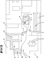
- Figure 2 shows a floor plan of an apartment within which the two soil cultivation devices 1, 2 are located.
- the apartment has a plurality of surrounding subareas 6, 7, 8, 9, of which the surrounding subareas 6, 9 are rooms of the apartment and the surrounding subareas 7, 8 are different areas of a room, namely a carpet (surrounding subarea 8), which is only used by the apartment First soil cultivation device 1 is to be cleaned, and the remaining area (subarea 9) of the room next to the carpet.
- Subareas 6, 7, 8, 9 of the surroundings can in principle be defined at will by a user of the system, in particular via the aforementioned application, or automatically determined by a computing device 12 of a soil cultivation device 1, 2.
- the first base station 18 is located in a first environmental sub-area 6 of the apartment, while the second base station 19 is here in a different subarea 9 of the surroundings.
- the soil cultivation devices 1, 2 and preferably also the base stations 18, 19 have a unique identification code by means of which they can be identified by other soil cultivation devices 1, 2 by means of a corresponding device.
- the identification code can be, for example, an optical code such as a barcode, QR code or the like.
- Electronic tags containing an identifiable code can also be used. Such tags can be, for example, RFID tags, NFC tags or Bluetooth beacons.
- the identification code of a soil cultivation device 1, 2 or a base station 18, 19 can be clearly identified and read out by appropriate detection devices.
- the identification codes are preferably stored in a memory device common to the soil cultivation devices 1, 2 or base stations 18, 19.
- the tillage devices 1, 2 have one or more Sensor devices for detecting a type of floor occurring in the subareas 6, 7, 8, 9, a type of soiling and / or a degree of soiling of a subarea 6, 7, 8, 9 of the environment .
- Hard floors include, for example, laminate, tiles and parquet.
- the devices for detecting the type of soil, the type of soiling or the degree of soiling can be optical or mechanical detection devices, for example.
- a camera with an image processing program can be used which is suitable for identifying a type of soil, type of soiling or a degree of soiling.
- the type of soiling can be, for example, soiling of different consistencies, for example liquid, solid, sticky or the like.
- the degree of pollution denotes a degree of pollution, for example divided into categories such as low, medium, high.
- a degree of soiling can also be specified as a percentage of the maximum possible soiling, as a dirt particle concentration per defined area subarea or the like.
- the first soil cultivation device 1 starts a journey to soil cultivation, for example starting from its base station 18, and follows a travel route 5 that meanders through the subareas 6, 7, 8, 9 of the surroundings, leaving out those areas which have obstacles 17 that cannot be driven under.
- the carpet in the surrounding subarea 8 can also be traversed and cleaned by the soil cultivation device 1.
- the detection device 11 detects the First soil cultivation device 1 Distances to obstacles 17, including room boundaries, within the surroundings of the first soil cultivation device 1.
- the environment map 4 contains a floor plan with the obstacles detected therein 17.
- the movement of the first soil preparation device 1 along the movement route 5 and the creation of the environment map 4 take place at the same time, so that the environment map 4 is continuously updated and expanded, the further the first soil cultivation device 1 proceeds along the travel route 5.
- a corresponding sensor system of the soil cultivation device 1 can recognize a type of soil, a degree of soiling and / or a type of soiling of one or more subareas 6, 7, 8, 9 and enter it directly in the map 4 of the environment, namely the subarea 6, 7, 8 concerned , Assign 9.
- the first soil cultivation device 1 is also designed to localize itself within the created environment map 4, ie to determine its own position and orientation within the environment.
- the first soil cultivation device 1 identifies the second soil cultivation device 2 on the basis of its unique identifier, namely, for example, a QR code applied to the housing of the second soil cultivation device 2, and clearly establishes its identity by comparing it with identification codes of various soil cultivation devices 1, 2 stored in a database.
- the unambiguous identification of the second soil cultivation device 2 by the first soil cultivation device 1 can furthermore also be supported by a communication between the two soil cultivation devices 1, 2.
- the first soil cultivation device 1 can send a request signal into the environment.
- This request signal can contain a request to other soil cultivation devices 1, 2 to look around in the area and also to search for soil cultivation devices 1, 2.
- That soil cultivation device 2, which then finds a soil cultivation device 1 in its surroundings, has detected the first soil cultivation device 1 with a high degree of probability. Both soil cultivation devices 1, 2 thus know which other soil cultivation device 1, 2 is in their vicinity.
- the first soil cultivation device 1 can, for example, detect the base station 19 of the second soil cultivation device 2 in the subarea 9 of the surroundings and recognize this on the basis of an identification code arranged on the base station 19. If the second soil cultivation device 2 has for its part created a local environment map 4, it can be determined which base station 18, 19 it is by comparing the local environment maps 4 of the second soil cultivation device 2 and the first soil cultivation device 1.
- the first soil cultivation device 1 now detects, as in FIG Figure 2
- the environment map 4 contains an estimated position of the second soil cultivation device 2.
- the second soil cultivation device 2 uses the received environment map 4, the second soil cultivation device 2 has knowledge of its current position in the area map 4 of the first Soil cultivation device 1, ie in the coordinates of the first soil cultivation device 1, information about cleaned areas on the route 5 of the first soil cultivation device 1 and information about soil types represented in the surrounding subareas 6, 7, 8, 9, for example also about the fact that in the surrounding subarea 8 a Carpet is lying, which cannot be cleaned by the second soil cultivation device 2 and should therefore not be driven on.
- the transmission of the environment map 4 to the second soil cultivation device 2 takes place in the exemplary embodiment according to FIG Figures 1 to 3 directly via wireless communication, without intermediate transmission to, for example, an external terminal, a server or the like.
- the second soil cultivation device 2 knows the information collected by the first soil cultivation device 1 about a soil type, a pollution type and / or a degree of pollution.
- the second soil cultivation device 2 has knowledge of the travel route 5 covered by the first soil cultivation device 1.
- the computing device 12 of the second soil cultivation device 2 can locally store the map 4 of the surroundings and plan its own travel route 10 for the second soil cultivation device 2, which here omits the subarea 8 of the surroundings, for example which contains the carpet.
- the first soil cultivation device 1 continues its soil cultivation activity and movement, that is, the soil cultivation of the second soil cultivation device 2 is started while the first tillage device 1 carries out its tillage activity.
- the soil cultivation activities can advantageously complement each other and be carried out in a time-saving manner, since the second soil cultivation device 2 does not wait must until the first tillage device 1 has finished its tillage activity.
- the second soil cultivation device 2 approaches those subareas 6, 7, 9 of the surroundings that are located on the travel route 5 of the first soil cultivation device 1 and have soil types that can or should be cleaned by the second soil cultivation device 2.
- the subarea 8 of the surroundings having the carpet is therefore not integrated into the travel route 10 of the second soil cultivation device 2.
- the first soil cultivation device 1 continues to detect obstacles 17 within the environment and expands or updates its environment map 4, which is then preferably continuously made available to the second soil cultivation device 2.
- a user of the system can, for example, have the progress of the soil cultivation activities of both soil cultivation devices 1, 2 displayed on an external terminal device, for example a mobile phone.
- the planning of the travel route 10 of the second soil cultivation device 2 can be linked to defined conditions. If, for example, the first soil cultivation device 1 has not yet cleaned a hard floor before the first soil cultivation device 1 has detected the second soil cultivation device 2, the second soil cultivation device 2, namely the mopping robot in this case, is not activated because it is only suitable for hard soil cultivation.
- the position of the second soil working device 2 detected by the first soil working device 1 is, however, noted within the map 4 of the surroundings.
- the first soil cultivation device 1 detects and cleans a hard floor, this is noted in the environment map 4 or a corresponding message is transmitted to the second soil cultivation device 2, so that the computing device 12 of the second soil cultivation device 2 carries out cleaning by the soil cultivation device 2 in this subarea 6 , 7, 9 can start.
- the start of the soil cultivation by the second soil cultivation device 2 can be made dependent on a minimum area size of a subarea 6, 7, 8, 9 to be cleaned. If the first soil cultivation device 1 only started cleaning a hard floor shortly before the detection of the second soil cultivation device 2, it makes sense to delay the start signal for soil cultivation by the second soil cultivation device 2 until a minimum area has been pre-cleaned, i.e. vacuumed, by the first soil cultivation device 1 , is. It is therefore proposed to start the second soil cultivation device 2 only when the hard floor surface that the first soil cultivation device 1 has already worked on has a minimum area size or has even been completely cleaned. At the same time, this means that that subarea 6, 7, 8, 9 could then also be completely mapped.
- the computing device 12 of the second soil cultivation device 2 starts a soil cultivation activity by the second soil cultivation device 2.
- a starting point for the soil cultivation activity of the second soil cultivation device 2 is preferably determined so that there is a shortest distance between one current location of the second soil cultivation device 2 and the subareas 6, 7, 9 to be cleaned or the planned route 10 of the second soil cultivation device 2 results. If the first soil cultivation device 1 has cleaned more than one hard floor surface to be cleaned by the second soil cultivation device 2, here the subareas 6, 7, 9, before the start of the second soil cultivation device 2, a shortest possible route 10 is planned for the second soil cultivation device 2, which contains all subareas 6, 7, 9 to be cleaned.
- the route of travel 10 of the second soil cultivation device 2 therefore does not have to be identical to the one Be the route of travel 5 of the first soil cultivation device 1.
- the time span and the amount of energy required for soil cultivation by the second soil cultivation device 2 can also be kept as low as possible.
- the travel route 10 for the second soil cultivation device 2 is advantageously changed or supplemented when the travel route 5 of the first soil cultivation device 1 also changes or supplements and relates to subareas 6, 7, 8, 9 that are also cleaned by the second soil cultivation device 2 should.
- the first tillage device 1 In the event that the first tillage device 1 does not detect any other tillage device 2 during its tillage activity, the first tillage device 1 ends its tillage activity according to plan and transmits information about its successful tillage to, for example, an external computing device 3 or other tillage devices 1, 2, which are known to the first soil cultivation device 1 within the system.
- a second soil cultivation device 2 can then carry out its own soil cultivation activity, although the first map 4 of the surroundings 4 of the first soil cultivation device 1 with a position of the second soil cultivation device 2 recorded therein is not available. Rather, the second soil cultivation device 2 must create its own map 4 of the surroundings, for which purpose the own detection device 11 of the second soil cultivation device 2 is used.
- the first soil cultivation device 1 can send a status notification to a so-called cloud after its soil cultivation activity has been successfully completed, by means of which the second soil cultivation device 2 in turn obtains information about the completed soil cultivation activity of the first soil cultivation device 1 and can start its own soil cultivation activity. Since the second soil cultivation device 2 therefore has no knowledge of the map 4 of the surroundings at the start of its soil cultivation activity, and also no knowledge of certain types of soil in partial areas of the surroundings 6, 7, 8, 9 of the environment, the second soil cultivation device 2 must first obtain its relevant information about the environment itself.
- FIG. 3 shows a further possible embodiment of the invention in which the soil cultivation devices 1, 2 do not communicate with one another directly, but rather via an external computing device 3.
- the first soil cultivation device 1 sends its environment map 4, created up to that point and continuously updated, to the external computing device 3.
- the environment map 4 is stored there and transmitted to the second soil cultivation device 2 or made available for retrieval.
- the environment map 4 is thus stored centrally within the external computing device 3 and is managed and updated there. Additional information about the subareas 6, 7, 8, 9 present in the environment map 4 is collected and / or exchanged, so that the tillage devices 1, 2 networked in the system basically only have to transmit status information and area information to the computing device 3.
- the computing device 3 can also have a cross-device, ie global, persistent environment map 4, in which information detected by the soil cultivation devices 1, 2, such as soil type, amount of dirt, dirt type and the like, is then entered.
- the soil cultivation devices 1, 2 can access the map of the surroundings 4 stored in the computing device 3 in order, for example, to transmit or obtain information about a current position and orientation of another soil cultivation device 1, 2.
Landscapes
- Engineering & Computer Science (AREA)
- Radar, Positioning & Navigation (AREA)
- Remote Sensing (AREA)
- Physics & Mathematics (AREA)
- Automation & Control Theory (AREA)
- General Physics & Mathematics (AREA)
- Aviation & Aerospace Engineering (AREA)
- Mechanical Engineering (AREA)
- Control Of Position, Course, Altitude, Or Attitude Of Moving Bodies (AREA)
- Management, Administration, Business Operations System, And Electronic Commerce (AREA)
- Electromagnetism (AREA)
- Computer Vision & Pattern Recognition (AREA)
- Multimedia (AREA)
- Processing Of Solid Wastes (AREA)
- Electric Vacuum Cleaner (AREA)
Applications Claiming Priority (1)
| Application Number | Priority Date | Filing Date | Title |
|---|---|---|---|
| DE102020100447.8A DE102020100447A1 (de) | 2020-01-10 | 2020-01-10 | Verfahren zum Betrieb eines Systems mit zwei sich selbsttätig fortbewegenden Bodenbearbeitungsgeräten sowie System zur Durchführung eines solchen Verfahrens |
Publications (2)
| Publication Number | Publication Date |
|---|---|
| EP3848770A1 true EP3848770A1 (fr) | 2021-07-14 |
| EP3848770B1 EP3848770B1 (fr) | 2022-07-27 |
Family
ID=74105864
Family Applications (1)
| Application Number | Title | Priority Date | Filing Date |
|---|---|---|---|
| EP21150448.5A Active EP3848770B1 (fr) | 2020-01-10 | 2021-01-07 | Procédé de fonctionnement d'un système pourvu de deux appareils de traitement du sol autonome et système destiné à la mise en oeuvre d'un tel procédé |
Country Status (5)
| Country | Link |
|---|---|
| US (1) | US11934199B2 (fr) |
| EP (1) | EP3848770B1 (fr) |
| CN (1) | CN113100661B (fr) |
| DE (1) | DE102020100447A1 (fr) |
| ES (1) | ES2926855T3 (fr) |
Families Citing this family (3)
| Publication number | Priority date | Publication date | Assignee | Title |
|---|---|---|---|---|
| DE102022202326A1 (de) | 2022-03-08 | 2023-09-14 | BSH Hausgeräte GmbH | Kooperative Bodenbearbeitung |
| CN116269044B (zh) * | 2023-01-10 | 2026-04-14 | 海尔机器人科技(青岛)有限公司 | 双子清洁机的清洁方法、装置、设备及产品 |
| US20240329640A1 (en) * | 2023-03-31 | 2024-10-03 | Omron Corporation | Systems and methods for map transformation between mobile robots |
Citations (5)
| Publication number | Priority date | Publication date | Assignee | Title |
|---|---|---|---|---|
| US6374155B1 (en) | 1999-11-24 | 2002-04-16 | Personal Robotics, Inc. | Autonomous multi-platform robot system |
| US20030212472A1 (en) * | 2002-05-10 | 2003-11-13 | Royal Appliance Mfg. Co. | Autonomous multi-platform robot system |
| EP3344104A1 (fr) * | 2015-09-03 | 2018-07-11 | Aktiebolaget Electrolux | Système de dispositifs de nettoyage robotisés |
| US20180344114A1 (en) * | 2017-06-05 | 2018-12-06 | Bissell Homecare, Inc. | Autonomous floor cleaning system |
| WO2020004824A1 (fr) * | 2018-06-25 | 2020-01-02 | Lg Electronics Inc. | Pluralité de dispositifs de nettoyage autonomes et procédé de commande associé |
Family Cites Families (9)
| Publication number | Priority date | Publication date | Assignee | Title |
|---|---|---|---|---|
| WO2014113091A1 (fr) * | 2013-01-18 | 2014-07-24 | Irobot Corporation | Systèmes de gestion environnementale comprenant des robots mobiles et procédés les utilisant |
| EP3293325B1 (fr) * | 2016-09-13 | 2021-08-25 | Maytronics Ltd. | Ensemble de robots de nettoyage de piscine |
| DE102016125224A1 (de) * | 2016-12-21 | 2018-06-21 | Vorwerk & Co. Interholding Gmbh | Verfahren zur Navigation und Selbstlokalisierung eines sich autonom fortbewegenden Bearbeitungsgerätes |
| DE102017113286A1 (de) * | 2017-06-16 | 2018-12-20 | Vorwerk & Co. Interholding Gmbh | System mit mindestens zwei sich selbsttätig fortbewegenden Bodenbearbeitungsgeräten |
| DE102017113288A1 (de) * | 2017-06-16 | 2018-12-20 | Vorwerk & Co. Interholding Gmbh | System mit mindestens zwei Bodenbearbeitungseinrichtungen |
| DE102017113287A1 (de) * | 2017-06-16 | 2018-12-20 | Vorwerk & Co. Interholding Gmbh | System mit mindestens zwei Bodenbearbeitungsgeräten |
| US11274929B1 (en) * | 2017-10-17 | 2022-03-15 | AI Incorporated | Method for constructing a map while performing work |
| US11614746B2 (en) * | 2018-01-05 | 2023-03-28 | Irobot Corporation | Mobile cleaning robot teaming and persistent mapping |
| US11341781B2 (en) * | 2019-10-18 | 2022-05-24 | Toyota Motor Engineering And Manufacturing North America, Inc. | Vehicular communications through identifiers and online systems |
-
2020
- 2020-01-10 DE DE102020100447.8A patent/DE102020100447A1/de not_active Withdrawn
-
2021
- 2021-01-07 ES ES21150448T patent/ES2926855T3/es active Active
- 2021-01-07 EP EP21150448.5A patent/EP3848770B1/fr active Active
- 2021-01-08 US US17/144,404 patent/US11934199B2/en active Active
- 2021-01-11 CN CN202110029916.XA patent/CN113100661B/zh active Active
Patent Citations (5)
| Publication number | Priority date | Publication date | Assignee | Title |
|---|---|---|---|---|
| US6374155B1 (en) | 1999-11-24 | 2002-04-16 | Personal Robotics, Inc. | Autonomous multi-platform robot system |
| US20030212472A1 (en) * | 2002-05-10 | 2003-11-13 | Royal Appliance Mfg. Co. | Autonomous multi-platform robot system |
| EP3344104A1 (fr) * | 2015-09-03 | 2018-07-11 | Aktiebolaget Electrolux | Système de dispositifs de nettoyage robotisés |
| US20180344114A1 (en) * | 2017-06-05 | 2018-12-06 | Bissell Homecare, Inc. | Autonomous floor cleaning system |
| WO2020004824A1 (fr) * | 2018-06-25 | 2020-01-02 | Lg Electronics Inc. | Pluralité de dispositifs de nettoyage autonomes et procédé de commande associé |
Also Published As
| Publication number | Publication date |
|---|---|
| US11934199B2 (en) | 2024-03-19 |
| CN113100661B (zh) | 2025-03-11 |
| CN113100661A (zh) | 2021-07-13 |
| ES2926855T3 (es) | 2022-10-31 |
| DE102020100447A1 (de) | 2021-07-15 |
| US20210216080A1 (en) | 2021-07-15 |
| EP3848770B1 (fr) | 2022-07-27 |
Similar Documents
| Publication | Publication Date | Title |
|---|---|---|
| EP3415070B1 (fr) | Système pourvu d'au moins deux dispositifs de traitement du sol | |
| EP3822730B1 (fr) | Procédé de fonctionnement d'un appareil de nettoyage de sol et appareil de nettoyage de sol | |
| EP3814067B1 (fr) | Exploration d'une zone d'intervention d'un robot par un robot mobile autonome | |
| EP2812766B1 (fr) | Procédé de déclenchement automatique d'une auto-localisation | |
| EP2898382B1 (fr) | Robot et procédé d'inspection autonome ou de traitement de surface | |
| EP3417350B1 (fr) | Procédé de contrôle d'un robot mobile autonome | |
| DE102011006062B4 (de) | Verfahren zur autonomen Inspektion einer Umgebung oder Bearbeitung von Bodenflächen | |
| EP3538967B1 (fr) | Procédé et dispositif de fonctionnement d'un robot se déplaçant de façon autonome | |
| EP3848770B1 (fr) | Procédé de fonctionnement d'un système pourvu de deux appareils de traitement du sol autonome et système destiné à la mise en oeuvre d'un tel procédé | |
| EP3416018B1 (fr) | Système pourvu d'au moins deux appareils de traitement du sol | |
| DE102014110104B4 (de) | System zur Steuerung von beweglichen Mobileinheiten | |
| DE102017104427A1 (de) | Verfahren zur Steuerung eines autonomen, mobilen Roboters | |
| WO2018202337A1 (fr) | Procédé de commande d'appareils de nettoyage | |
| WO2007036487A2 (fr) | Procédé permettant de faire fonctionner un appareil électroménager à déplacement autonome et procédé permettant de faire fonctionner une station de base | |
| DE102017127180A1 (de) | Bodenbearbeitung mittels eines autonomen mobilen Roboters | |
| EP3367200A1 (fr) | Procédé de fonctionnement d'un robot en mouvement de manière automatique | |
| EP3559773B1 (fr) | Procédé de navigation et localisation automatique d'un appareil d'usinage à déplacement autonome | |
| EP3825802A1 (fr) | Système comprenant au moins deux robots autonomes de nettoyage et procédé d'exploitation du système | |
| EP3812869B1 (fr) | Procédé d'établissement d'une carte d'environnement pour un appareil de traitement du sol autonome, ainsi qu'un système de deux appareils de traitement du sol autonome | |
| DE102021205620A1 (de) | Verfahren zum Bestimmen eines Bewegungspfades auf einem Untergrund | |
| EP3851929B1 (fr) | Procédé de fonctionnement d'un système comprenant au moins deux appareils de traitement du sol mobiles automatiques ainsi que système de mise en oeuvre d'un tel procédé | |
| DE102018131732A1 (de) | System aus mindestens einem Bodenbearbeitungsgerät und mindestens einer Signalsendeeinrichtung sowie Betriebsverfahren dafür | |
| DE102018132175A1 (de) | System mit zwei Bodenbearbeitungsgeräten und Verfahren dafür | |
| DE102024208730A1 (de) | Verfahren zum Bestimmen eines Bewegungspfads für ein mobiles Gerät |
Legal Events
| Date | Code | Title | Description |
|---|---|---|---|
| PUAI | Public reference made under article 153(3) epc to a published international application that has entered the european phase |
Free format text: ORIGINAL CODE: 0009012 |
|
| STAA | Information on the status of an ep patent application or granted ep patent |
Free format text: STATUS: THE APPLICATION HAS BEEN PUBLISHED |
|
| AK | Designated contracting states |
Kind code of ref document: A1 Designated state(s): AL AT BE BG CH CY CZ DE DK EE ES FI FR GB GR HR HU IE IS IT LI LT LU LV MC MK MT NL NO PL PT RO RS SE SI SK SM TR |
|
| STAA | Information on the status of an ep patent application or granted ep patent |
Free format text: STATUS: REQUEST FOR EXAMINATION WAS MADE |
|
| 17P | Request for examination filed |
Effective date: 20210907 |
|
| RBV | Designated contracting states (corrected) |
Designated state(s): AL AT BE BG CH CY CZ DE DK EE ES FI FR GB GR HR HU IE IS IT LI LT LU LV MC MK MT NL NO PL PT RO RS SE SI SK SM TR |
|
| GRAP | Despatch of communication of intention to grant a patent |
Free format text: ORIGINAL CODE: EPIDOSNIGR1 |
|
| STAA | Information on the status of an ep patent application or granted ep patent |
Free format text: STATUS: GRANT OF PATENT IS INTENDED |
|
| INTG | Intention to grant announced |
Effective date: 20220223 |
|
| GRAS | Grant fee paid |
Free format text: ORIGINAL CODE: EPIDOSNIGR3 |
|
| GRAA | (expected) grant |
Free format text: ORIGINAL CODE: 0009210 |
|
| STAA | Information on the status of an ep patent application or granted ep patent |
Free format text: STATUS: THE PATENT HAS BEEN GRANTED |
|
| AK | Designated contracting states |
Kind code of ref document: B1 Designated state(s): AL AT BE BG CH CY CZ DE DK EE ES FI FR GB GR HR HU IE IS IT LI LT LU LV MC MK MT NL NO PL PT RO RS SE SI SK SM TR |
|
| REG | Reference to a national code |
Ref country code: CH Ref legal event code: EP |
|
| REG | Reference to a national code |
Ref country code: AT Ref legal event code: REF Ref document number: 1507480 Country of ref document: AT Kind code of ref document: T Effective date: 20220815 |
|
| REG | Reference to a national code |
Ref country code: DE Ref legal event code: R096 Ref document number: 502021000079 Country of ref document: DE |
|
| REG | Reference to a national code |
Ref country code: IE Ref legal event code: FG4D Free format text: LANGUAGE OF EP DOCUMENT: GERMAN |
|
| REG | Reference to a national code |
Ref country code: ES Ref legal event code: FG2A Ref document number: 2926855 Country of ref document: ES Kind code of ref document: T3 Effective date: 20221031 |
|
| REG | Reference to a national code |
Ref country code: LT Ref legal event code: MG9D |
|
| REG | Reference to a national code |
Ref country code: NL Ref legal event code: MP Effective date: 20220727 |
|
| PG25 | Lapsed in a contracting state [announced via postgrant information from national office to epo] |
Ref country code: SE Free format text: LAPSE BECAUSE OF FAILURE TO SUBMIT A TRANSLATION OF THE DESCRIPTION OR TO PAY THE FEE WITHIN THE PRESCRIBED TIME-LIMIT Effective date: 20220727 Ref country code: RS Free format text: LAPSE BECAUSE OF FAILURE TO SUBMIT A TRANSLATION OF THE DESCRIPTION OR TO PAY THE FEE WITHIN THE PRESCRIBED TIME-LIMIT Effective date: 20220727 Ref country code: PT Free format text: LAPSE BECAUSE OF FAILURE TO SUBMIT A TRANSLATION OF THE DESCRIPTION OR TO PAY THE FEE WITHIN THE PRESCRIBED TIME-LIMIT Effective date: 20221128 Ref country code: NO Free format text: LAPSE BECAUSE OF FAILURE TO SUBMIT A TRANSLATION OF THE DESCRIPTION OR TO PAY THE FEE WITHIN THE PRESCRIBED TIME-LIMIT Effective date: 20221027 Ref country code: NL Free format text: LAPSE BECAUSE OF FAILURE TO SUBMIT A TRANSLATION OF THE DESCRIPTION OR TO PAY THE FEE WITHIN THE PRESCRIBED TIME-LIMIT Effective date: 20220727 Ref country code: LV Free format text: LAPSE BECAUSE OF FAILURE TO SUBMIT A TRANSLATION OF THE DESCRIPTION OR TO PAY THE FEE WITHIN THE PRESCRIBED TIME-LIMIT Effective date: 20220727 Ref country code: LT Free format text: LAPSE BECAUSE OF FAILURE TO SUBMIT A TRANSLATION OF THE DESCRIPTION OR TO PAY THE FEE WITHIN THE PRESCRIBED TIME-LIMIT Effective date: 20220727 Ref country code: FI Free format text: LAPSE BECAUSE OF FAILURE TO SUBMIT A TRANSLATION OF THE DESCRIPTION OR TO PAY THE FEE WITHIN THE PRESCRIBED TIME-LIMIT Effective date: 20220727 |
|
| PG25 | Lapsed in a contracting state [announced via postgrant information from national office to epo] |
Ref country code: PL Free format text: LAPSE BECAUSE OF FAILURE TO SUBMIT A TRANSLATION OF THE DESCRIPTION OR TO PAY THE FEE WITHIN THE PRESCRIBED TIME-LIMIT Effective date: 20220727 Ref country code: IS Free format text: LAPSE BECAUSE OF FAILURE TO SUBMIT A TRANSLATION OF THE DESCRIPTION OR TO PAY THE FEE WITHIN THE PRESCRIBED TIME-LIMIT Effective date: 20221127 Ref country code: HR Free format text: LAPSE BECAUSE OF FAILURE TO SUBMIT A TRANSLATION OF THE DESCRIPTION OR TO PAY THE FEE WITHIN THE PRESCRIBED TIME-LIMIT Effective date: 20220727 Ref country code: GR Free format text: LAPSE BECAUSE OF FAILURE TO SUBMIT A TRANSLATION OF THE DESCRIPTION OR TO PAY THE FEE WITHIN THE PRESCRIBED TIME-LIMIT Effective date: 20221028 |
|
| PG25 | Lapsed in a contracting state [announced via postgrant information from national office to epo] |
Ref country code: SM Free format text: LAPSE BECAUSE OF FAILURE TO SUBMIT A TRANSLATION OF THE DESCRIPTION OR TO PAY THE FEE WITHIN THE PRESCRIBED TIME-LIMIT Effective date: 20220727 Ref country code: RO Free format text: LAPSE BECAUSE OF FAILURE TO SUBMIT A TRANSLATION OF THE DESCRIPTION OR TO PAY THE FEE WITHIN THE PRESCRIBED TIME-LIMIT Effective date: 20220727 Ref country code: DK Free format text: LAPSE BECAUSE OF FAILURE TO SUBMIT A TRANSLATION OF THE DESCRIPTION OR TO PAY THE FEE WITHIN THE PRESCRIBED TIME-LIMIT Effective date: 20220727 Ref country code: CZ Free format text: LAPSE BECAUSE OF FAILURE TO SUBMIT A TRANSLATION OF THE DESCRIPTION OR TO PAY THE FEE WITHIN THE PRESCRIBED TIME-LIMIT Effective date: 20220727 |
|
| REG | Reference to a national code |
Ref country code: DE Ref legal event code: R097 Ref document number: 502021000079 Country of ref document: DE |
|
| PG25 | Lapsed in a contracting state [announced via postgrant information from national office to epo] |
Ref country code: SK Free format text: LAPSE BECAUSE OF FAILURE TO SUBMIT A TRANSLATION OF THE DESCRIPTION OR TO PAY THE FEE WITHIN THE PRESCRIBED TIME-LIMIT Effective date: 20220727 Ref country code: EE Free format text: LAPSE BECAUSE OF FAILURE TO SUBMIT A TRANSLATION OF THE DESCRIPTION OR TO PAY THE FEE WITHIN THE PRESCRIBED TIME-LIMIT Effective date: 20220727 |
|
| PLBE | No opposition filed within time limit |
Free format text: ORIGINAL CODE: 0009261 |
|
| STAA | Information on the status of an ep patent application or granted ep patent |
Free format text: STATUS: NO OPPOSITION FILED WITHIN TIME LIMIT |
|
| P01 | Opt-out of the competence of the unified patent court (upc) registered |
Effective date: 20230517 |
|
| PG25 | Lapsed in a contracting state [announced via postgrant information from national office to epo] |
Ref country code: AL Free format text: LAPSE BECAUSE OF FAILURE TO SUBMIT A TRANSLATION OF THE DESCRIPTION OR TO PAY THE FEE WITHIN THE PRESCRIBED TIME-LIMIT Effective date: 20220727 |
|
| 26N | No opposition filed |
Effective date: 20230502 |
|
| PG25 | Lapsed in a contracting state [announced via postgrant information from national office to epo] |
Ref country code: SI Free format text: LAPSE BECAUSE OF FAILURE TO SUBMIT A TRANSLATION OF THE DESCRIPTION OR TO PAY THE FEE WITHIN THE PRESCRIBED TIME-LIMIT Effective date: 20220727 |
|
| PG25 | Lapsed in a contracting state [announced via postgrant information from national office to epo] |
Ref country code: LU Free format text: LAPSE BECAUSE OF NON-PAYMENT OF DUE FEES Effective date: 20230107 |
|
| REG | Reference to a national code |
Ref country code: BE Ref legal event code: MM Effective date: 20230131 |
|
| REG | Reference to a national code |
Ref country code: DE Ref legal event code: R079 Ref document number: 502021000079 Country of ref document: DE Free format text: PREVIOUS MAIN CLASS: G05D0001020000 Ipc: G05D0001430000 |
|
| PG25 | Lapsed in a contracting state [announced via postgrant information from national office to epo] |
Ref country code: BE Free format text: LAPSE BECAUSE OF NON-PAYMENT OF DUE FEES Effective date: 20230131 |
|
| PG25 | Lapsed in a contracting state [announced via postgrant information from national office to epo] |
Ref country code: IE Free format text: LAPSE BECAUSE OF NON-PAYMENT OF DUE FEES Effective date: 20230107 |
|
| PG25 | Lapsed in a contracting state [announced via postgrant information from national office to epo] |
Ref country code: MC Free format text: LAPSE BECAUSE OF FAILURE TO SUBMIT A TRANSLATION OF THE DESCRIPTION OR TO PAY THE FEE WITHIN THE PRESCRIBED TIME-LIMIT Effective date: 20220727 |
|
| PG25 | Lapsed in a contracting state [announced via postgrant information from national office to epo] |
Ref country code: MC Free format text: LAPSE BECAUSE OF FAILURE TO SUBMIT A TRANSLATION OF THE DESCRIPTION OR TO PAY THE FEE WITHIN THE PRESCRIBED TIME-LIMIT Effective date: 20220727 |
|
| REG | Reference to a national code |
Ref country code: CH Ref legal event code: PL |
|
| PG25 | Lapsed in a contracting state [announced via postgrant information from national office to epo] |
Ref country code: CH Free format text: LAPSE BECAUSE OF NON-PAYMENT OF DUE FEES Effective date: 20240131 |
|
| PG25 | Lapsed in a contracting state [announced via postgrant information from national office to epo] |
Ref country code: CH Free format text: LAPSE BECAUSE OF NON-PAYMENT OF DUE FEES Effective date: 20240131 |
|
| PG25 | Lapsed in a contracting state [announced via postgrant information from national office to epo] |
Ref country code: BG Free format text: LAPSE BECAUSE OF FAILURE TO SUBMIT A TRANSLATION OF THE DESCRIPTION OR TO PAY THE FEE WITHIN THE PRESCRIBED TIME-LIMIT Effective date: 20220727 |
|
| PG25 | Lapsed in a contracting state [announced via postgrant information from national office to epo] |
Ref country code: BG Free format text: LAPSE BECAUSE OF FAILURE TO SUBMIT A TRANSLATION OF THE DESCRIPTION OR TO PAY THE FEE WITHIN THE PRESCRIBED TIME-LIMIT Effective date: 20220727 |
|
| PGFP | Annual fee paid to national office [announced via postgrant information from national office to epo] |
Ref country code: AT Payment date: 20250417 Year of fee payment: 5 |
|
| PG25 | Lapsed in a contracting state [announced via postgrant information from national office to epo] |
Ref country code: CY Free format text: LAPSE BECAUSE OF FAILURE TO SUBMIT A TRANSLATION OF THE DESCRIPTION OR TO PAY THE FEE WITHIN THE PRESCRIBED TIME-LIMIT; INVALID AB INITIO Effective date: 20210107 |
|
| PG25 | Lapsed in a contracting state [announced via postgrant information from national office to epo] |
Ref country code: HU Free format text: LAPSE BECAUSE OF FAILURE TO SUBMIT A TRANSLATION OF THE DESCRIPTION OR TO PAY THE FEE WITHIN THE PRESCRIBED TIME-LIMIT; INVALID AB INITIO Effective date: 20210107 |
|
| GBPC | Gb: european patent ceased through non-payment of renewal fee |
Effective date: 20250107 |
|
| PG25 | Lapsed in a contracting state [announced via postgrant information from national office to epo] |
Ref country code: GB Free format text: LAPSE BECAUSE OF NON-PAYMENT OF DUE FEES Effective date: 20250107 |
|
| PG25 | Lapsed in a contracting state [announced via postgrant information from national office to epo] |
Ref country code: TR Free format text: LAPSE BECAUSE OF FAILURE TO SUBMIT A TRANSLATION OF THE DESCRIPTION OR TO PAY THE FEE WITHIN THE PRESCRIBED TIME-LIMIT Effective date: 20220727 |
|
| PGFP | Annual fee paid to national office [announced via postgrant information from national office to epo] |
Ref country code: ES Payment date: 20260217 Year of fee payment: 6 |
|
| PGFP | Annual fee paid to national office [announced via postgrant information from national office to epo] |
Ref country code: DE Payment date: 20260120 Year of fee payment: 6 |
|
| PGFP | Annual fee paid to national office [announced via postgrant information from national office to epo] |
Ref country code: IT Payment date: 20260130 Year of fee payment: 6 |
|
| PGFP | Annual fee paid to national office [announced via postgrant information from national office to epo] |
Ref country code: FR Payment date: 20260121 Year of fee payment: 6 |