EP3851157A1 - Instrument de physiothérapie douce et son procédé d'utilisation - Google Patents
Instrument de physiothérapie douce et son procédé d'utilisation Download PDFInfo
- Publication number
- EP3851157A1 EP3851157A1 EP20209517.0A EP20209517A EP3851157A1 EP 3851157 A1 EP3851157 A1 EP 3851157A1 EP 20209517 A EP20209517 A EP 20209517A EP 3851157 A1 EP3851157 A1 EP 3851157A1
- Authority
- EP
- European Patent Office
- Prior art keywords
- functional layers
- carbon nanotube
- layer
- electrodes
- flexible
- Prior art date
- Legal status (The legal status is an assumption and is not a legal conclusion. Google has not performed a legal analysis and makes no representation as to the accuracy of the status listed.)
- Granted
Links
Images


Classifications
-
- A—HUMAN NECESSITIES
- A61—MEDICAL OR VETERINARY SCIENCE; HYGIENE
- A61N—ELECTROTHERAPY; MAGNETOTHERAPY; RADIATION THERAPY; ULTRASOUND THERAPY
- A61N1/00—Electrotherapy; Circuits therefor
- A61N1/02—Details
- A61N1/04—Electrodes
- A61N1/0404—Electrodes for external use
- A61N1/0408—Use-related aspects
- A61N1/0452—Specially adapted for transcutaneous muscle stimulation [TMS]
-
- A—HUMAN NECESSITIES
- A61—MEDICAL OR VETERINARY SCIENCE; HYGIENE
- A61N—ELECTROTHERAPY; MAGNETOTHERAPY; RADIATION THERAPY; ULTRASOUND THERAPY
- A61N1/00—Electrotherapy; Circuits therefor
- A61N1/18—Applying electric currents by contact electrodes
- A61N1/32—Applying electric currents by contact electrodes alternating or intermittent currents
- A61N1/328—Applying electric currents by contact electrodes alternating or intermittent currents for improving the appearance of the skin, e.g. facial toning or wrinkle treatment
-
- A—HUMAN NECESSITIES
- A45—HAND OR TRAVELLING ARTICLES
- A45D—HAIRDRESSING OR SHAVING EQUIPMENT; EQUIPMENT FOR COSMETICS OR COSMETIC TREATMENTS, e.g. FOR MANICURING OR PEDICURING
- A45D44/00—Other cosmetic or toiletry articles, e.g. for hairdressers' rooms
- A45D44/002—Masks for cosmetic treatment of the face
-
- A—HUMAN NECESSITIES
- A61—MEDICAL OR VETERINARY SCIENCE; HYGIENE
- A61N—ELECTROTHERAPY; MAGNETOTHERAPY; RADIATION THERAPY; ULTRASOUND THERAPY
- A61N1/00—Electrotherapy; Circuits therefor
- A61N1/02—Details
- A61N1/04—Electrodes
- A61N1/0404—Electrodes for external use
- A61N1/0408—Use-related aspects
- A61N1/0456—Specially adapted for transcutaneous electrical nerve stimulation [TENS]
-
- A—HUMAN NECESSITIES
- A61—MEDICAL OR VETERINARY SCIENCE; HYGIENE
- A61N—ELECTROTHERAPY; MAGNETOTHERAPY; RADIATION THERAPY; ULTRASOUND THERAPY
- A61N1/00—Electrotherapy; Circuits therefor
- A61N1/02—Details
- A61N1/04—Electrodes
- A61N1/0404—Electrodes for external use
- A61N1/0472—Structure-related aspects
- A61N1/0476—Array electrodes (including any electrode arrangement with more than one electrode for at least one of the polarities)
-
- A—HUMAN NECESSITIES
- A61—MEDICAL OR VETERINARY SCIENCE; HYGIENE
- A61N—ELECTROTHERAPY; MAGNETOTHERAPY; RADIATION THERAPY; ULTRASOUND THERAPY
- A61N1/00—Electrotherapy; Circuits therefor
- A61N1/02—Details
- A61N1/04—Electrodes
- A61N1/0404—Electrodes for external use
- A61N1/0472—Structure-related aspects
- A61N1/0492—Patch electrodes
-
- A—HUMAN NECESSITIES
- A61—MEDICAL OR VETERINARY SCIENCE; HYGIENE
- A61N—ELECTROTHERAPY; MAGNETOTHERAPY; RADIATION THERAPY; ULTRASOUND THERAPY
- A61N1/00—Electrotherapy; Circuits therefor
- A61N1/18—Applying electric currents by contact electrodes
- A61N1/32—Applying electric currents by contact electrodes alternating or intermittent currents
- A61N1/36—Applying electric currents by contact electrodes alternating or intermittent currents for stimulation
- A61N1/36014—External stimulators, e.g. with patch electrodes
-
- A—HUMAN NECESSITIES
- A61—MEDICAL OR VETERINARY SCIENCE; HYGIENE
- A61N—ELECTROTHERAPY; MAGNETOTHERAPY; RADIATION THERAPY; ULTRASOUND THERAPY
- A61N1/00—Electrotherapy; Circuits therefor
- A61N1/18—Applying electric currents by contact electrodes
- A61N1/32—Applying electric currents by contact electrodes alternating or intermittent currents
- A61N1/36—Applying electric currents by contact electrodes alternating or intermittent currents for stimulation
- A61N1/36014—External stimulators, e.g. with patch electrodes
- A61N1/3603—Control systems
-
- A—HUMAN NECESSITIES
- A61—MEDICAL OR VETERINARY SCIENCE; HYGIENE
- A61N—ELECTROTHERAPY; MAGNETOTHERAPY; RADIATION THERAPY; ULTRASOUND THERAPY
- A61N1/00—Electrotherapy; Circuits therefor
- A61N1/02—Details
- A61N1/04—Electrodes
- A61N1/0404—Electrodes for external use
- A61N1/0472—Structure-related aspects
- A61N1/0484—Garment electrodes worn by the patient
-
- A—HUMAN NECESSITIES
- A61—MEDICAL OR VETERINARY SCIENCE; HYGIENE
- A61N—ELECTROTHERAPY; MAGNETOTHERAPY; RADIATION THERAPY; ULTRASOUND THERAPY
- A61N1/00—Electrotherapy; Circuits therefor
- A61N1/02—Details
- A61N1/04—Electrodes
- A61N1/0404—Electrodes for external use
- A61N1/0472—Structure-related aspects
- A61N1/0492—Patch electrodes
- A61N1/0496—Patch electrodes characterised by using specific chemical compositions, e.g. hydrogel compositions, adhesives
-
- A—HUMAN NECESSITIES
- A61—MEDICAL OR VETERINARY SCIENCE; HYGIENE
- A61N—ELECTROTHERAPY; MAGNETOTHERAPY; RADIATION THERAPY; ULTRASOUND THERAPY
- A61N1/00—Electrotherapy; Circuits therefor
- A61N1/18—Applying electric currents by contact electrodes
- A61N1/20—Applying electric currents by contact electrodes continuous direct currents
- A61N1/205—Applying electric currents by contact electrodes continuous direct currents for promoting a biological process
Definitions
- the subject matter herein generally relates to a soft physiotherapy instrument.
- contact is defined as a direct and physical contact.
- substantially is defined to be that while essentially conforming to the particular dimension, shape, or other feature that is described, the component is not or need not be exactly conforming to the description.
- comprising when utilized, means “including, but not necessarily limited to”; it specifically indicates open-ended inclusion or membership in the so-described combination, group, series, and the like.
- the soft physiotherapy instrument 10 includes a flexible sheet 100, a controller 112 and a connection wire 114, the controller 112 is used for controlling the flexible sheet 100 via the connection wire 114.
- the controller 112 is movably connected with the flexible sheet 100 via the connection wire 114.
- the flexible sheet 100 includes a first flexible layer 102 and a second flexible layer 106 overlapped with each other (for clarity of display, in FIG. 2 , the first flexible layer 102 and the second flexible layer 106 are separately shown), the first flexible layer 102 and the second flexible layer 106 have corresponding eye and mouth openings (not labeled).
- the flexible sheet 100 further includes a plurality of functional layers 104 sandwiched between the first flexible layer 102 and the second flexible layer 106, the plurality of functional layers 104 are symmetrically distributed or regularly distributed, and a plurality of electrodes 108, each of the plurality of electrodes 108 is electrically connected with a single functional layer 104 or a pair of functional layers 104.
- the controller 112 is electrically connected with the plurality of electrodes 108 via the connection wire.
- the flexible sheet 100 defines a first region (not labeled) and a second region (not labeled).
- the plurality of functional layers 104 comprises a plurality of first functional layers 104a and a plurality of second functional layers 104b.
- the plurality of first functional layers 104a are located in the first region.
- the plurality of second functional layers 104b are located in the second region.
- a quantity of the first functional layers 104a is 2K
- a quantity of the second functional layers 104b is M
- K is greater than or equal to M.
- the 2K first functional layers 104a are symmetrically distributed on the first region of flexible sheet 100.
- a quantity of pairs of the first functional layers 104a is the same as the quantity of the electrodes 108, and number of each pair of the first functional layers 104a is the same as the number of electrode 108 electrically connected with the pair of first functional layers 104a.
- Each of the plurality of second functional layers 104b is electrically connected with one electrode. Numbers of two electrodes electrically connected with adjacent second functional layers 104b is x and y, and a difference between x and y is greater than or equal to 2.
- the quantity of plurality of first functional layers 104a is 8, of which the 8 first functional layers 104a are symmetrically distributed in the first region of the flexible facial mask 100; and 2 second functional layers 104b are located in the second region of the flexible facial mask 100.
- Each electrode 108 is numbered 1, 2, 3, and 4 in order from the left to the right of the end position connected to the controller 112, corresponding to the number of the electrode 108, and each pair of symmetrical main functional layers 104a are sequentially numbered from top to bottom of the flexible facial mask 100.
- one of the second functional layers 104b is electrically connected to the electrode 108 numbered 1, and the other functional layer 104b is connected to the electrode numbered 4. That is, the difference between x and y is 3.
- the controller 112 is configured to control the plurality of functional layers 104 in the flexible sheet 100 through the K electrodes 108.
- the K electrodes extend from the inside of the flexible facial mask 100 and converge in the connection wire 114, and the controller 112 is connected with the flexible sheet 100 through the connection wire 114.
- the controller 112 comprises a plurality of buttons for controlling the flexible sheet 100.
- the controller 112 is used to input a voltage between two of the plurality of electrodes 108 to produce current in the plurality of functional layers 104.
- a circuit is formed between the controller, the two of the plurality of electrodes 108, the plurality of functional layers 104 electrically connected with the two of the plurality of electrodes 108, and the skin of the user.
- the current flows through the controller, the two of the plurality of electrodes 108, the plurality of functional layers 104 electrically connected with the two of the plurality of electrodes 108, and the skin of the user.
- Each of the plurality of function buttons can control the current magnitude, the frequency of the current, the position of the input current, etc., to control the plurality of functional layers 104 inside the flexible sheet 100.
- the flexible sheet 100 can be movably coupled to the controller 200.
- the first flexible layer 102 or the second flexible layer 106 can include a window 110, and the plurality of electrodes 108 a first electrode lead 114 and a second electrode lead 116 are exposed from the window 110 and electrically connected to the controller 200 via a plurality of lead wires 108a.
- the window 110 is provided with an access port through which the controller 200 is connected to the flexible sheet 100.
- the flexible sheet 100 can be replaced as needed.
- the flexible sheet 100 can also be cleaned for reuse.
- the K electrodes 108 are electrically connected to the K pairs of first functional layers 104a, and at the same time, are electrically connected to the M second functional layers 104b. This connection mode does not require additional electrodes to be electrically connected to the M second functional layers 104b except the K electrodes 108.
- the quantity of electrodes 108 is saved. Since the K electrodes 108 extend from the flexible sheet 100 and converge in the connection wire 114, the diameter of the connection wire 114 can be small. It can be understood that the smaller the diameter of the connection wire 114, the better the flexibility of the connection wire 114.
- the flexible sheet 100 and the controller 112 are connected by the connection wire 114. The better the flexibility of the connecting wire 114, the better the user experience.
- Each of the plurality of electrodes 108 is electrically connected with a pair of first functional layers 104a.
- the flexible sheet 100 is applied on a user's skin, and a voltage is applied to two electrodes 108, the voltage is applied between the two electrodes 108 in cycles of 1 and 2, 2 and 3, 3 and 4... K-1 and K, so as to circulate the two pairs of first functional layers 104a corresponding to each two electrodes 108.
- a loop is formed between the controller 112, the two electrodes 108, two pairs of first functional layers 104a, the skin of the user between the two first functional layers 104a on one side, the skin of the user between the two first functional layers 104a on the other side.
- a current is generated in the loop, as such, the skin of the user between the two first functional layers 104a on one side and the skin of the user between the two first functional layers 104a on the other side are stimulated.
- the two electrodes 108 with two neighbor number, e,g., K-1 and K, are connected with the two pair of first functional layer 104a, wherein the two functional layers 104a on the same side are located adjacent with each other and named adjacent functional layers, and there is no other functional layer 104a located between the adjacent functional layers on the same side.
- the user's skin located between the adjacent functional layers is stimulated. In this way, by sequentially or selectively applying voltage to the two electrodes 108 with adjacent numbers, the purpose of sequentially or selectively stimulating the skin of the user at different positions in the first region can be achieved.
- the controller 112 can also input a voltage between two electrodes 108 that are not adjacent in number.
- the two pairs of first function layers 104a corresponding to the two electrodes 108 comprises two first functional layers 104a on the same side separated with each other.
- the two first functional layers 104a on the same side is separated by at least one first functional layer 104a on the same side of the flexible sheet 100.
- the two electrodes 108 numbered x and y are respectively connected to two second functional layers 104b, input voltage on the two electrodes 108, then another loop is formed between the two electrodes 108, the two second functional layers 104b, the facial skin between the two second functional layers 104b and the controller 112. Since the two electrically connected second functional layers 104b are adjacent to each other, the current value is relatively large, which can stimulate the skin between the two secondary functional layers 104b. As such, the skin in the second area is stimulated.
- the controller 112 when the controller 112 chooses to apply a voltage between two electrodes 108 that have numbers not adjacent, it will not stimulate the skin between the first functional layers 104a in the first region, but it can stimulate the skin between the second functional layers 104b in the second region.
- a material of the first flexible layer 102 or the second flexible layer 106 can be a flexible material such as non-woven fabric, silk, flexible cloth, porous flexible paper, or silica gel, and can be directly attached to a person's skin.
- a thickness of the first flexible layer 102 or the second flexible layer 106 can be set according to actual needs. In this embodiment, the thickness of the first flexible layer 102 or the second flexible layer 106 is in a range from 10 to 100 micrometers. In use of the soft physiotherapy instrument, the second flexible layer 106 will be directly attached on a skin.
- the second flexible layer 106 can have a porous structure.
- the flexible sheet 100 can be applied to any part of the human body, such as the back, legs, knees, and abdomen.
- the flexible sheet 100 can also be a part of clothes or other wearables.
- the flexible sheet 100 can be arranged on a clothes (not labeled) to serve as a shoulder and neck physiotherapy device, and the controller 112 can be built into clothing. It can be understood that, in other embodiments, the controller may also be placed outside the clothes.
- the flexible sheet 100 can also be directly made into clothing or other wearing objects.
- a material of the electrode 108 can be metal, alloy, indium tin oxide (ITO), antimony tin oxide (ATO), conductive silver paste, conductive polymer, or conductive carbon nanotube.
- the metal or the alloy can be aluminum, copper, tungsten, molybdenum, gold, titanium, rhodium, palladium, iridium, or any alloy thereof.
- the K electrodes 108 are all copper wires with a diameter of 1 micrometer.
- an insulating layer can be coated on the out surface of each of the K electrodes 108.
- a material of the insulating layer can be a flexible material.
- Each of the plurality of functional layer 104 can comprise a carbon nanotube layer or can be the carbon nanotube layer.
- the carbon nanotube layer includes a plurality of carbon nanotubes joined by van der Waals attractive force therebetween.
- the carbon nanotube layer can be a substantially pure structure of carbon nanotubes, with few impurities.
- the carbon nanotube layer can be a freestanding structure, that is, the carbon nanotube layer can be supported by itself without a substrate. For example, if at least one point of the carbon nanotube layer is held, the entire carbon nanotube layer can be lifted while remaining its structural integrity.
- the carbon nanotubes in the carbon nanotube layer can be orderly or disorderly arranged.
- the term 'disordered carbon nanotube layer' refers to a structure where the carbon nanotubes are arranged along different directions, and the aligning directions of the carbon nanotubes are random.
- the number of the carbon nanotubes arranged along each different direction can be almost the same (e.g. uniformly disordered).
- the disordered carbon nanotube layer can be isotropic, namely the carbon nanotube layer has properties identical in all directions of the carbon nanotube layer.
- the carbon nanotubes in the disordered carbon nanotube layer can be entangled with each other.
- the carbon nanotube layer including ordered carbon nanotubes is an ordered carbon nanotube layer.
- the term 'ordered carbon nanotube layer' refers to a structure where the carbon nanotubes are arranged in a consistently systematic manner, e.g., the carbon nanotubes are arranged approximately along a same direction and/or have two or more sections within each of which the carbon nanotubes are arranged approximately along a same direction (different sections can have different directions).
- the carbon nanotubes in the carbon nanotube layer can be selected from single-walled, double-walled, and/or multi-walled carbon nanotubes.
- the carbon nanotube layer may include at least one carbon nanotube film.
- the carbon nanotube layer is composed of one carbon nanotube film or at least two carbon nanotube films.
- the carbon nanotube layer consists one carbon nanotube film or at least two carbon nanotube films.
- the carbon nanotube film can be a drawn carbon nanotube film.
- the drawn carbon nanotube film includes a number of successive and oriented carbon nanotubes joined end-to-end by van der Waals attractive force therebetween.
- the drawn carbon nanotube film is a freestanding film.
- Each drawn carbon nanotube film includes a number of successively oriented carbon nanotube segments joined end-to-end by van der Waals attractive force therebetween.
- each carbon nanotube segment 143 includes a number of carbon nanotubes 145 substantially parallel to each other, and joined by van der Waals attractive force therebetween.
- the drawn carbon nanotube film can be treated with an organic solvent to increase mechanical strength and toughness of the drawn carbon nanotube film and reduce coefficient of friction of the drawn carbon nanotube film.
- a thickness of the drawn carbon nanotube film may range from about 0.5 nanometers to about 100 micrometers.
- the drawn carbon nanotube film can be used as a carbon nanotube layer directly.
- the carbon nanotubes in the drawn carbon nanotube film can be single-walled, double-walled, and/or multi-walled carbon nanotubes.
- the diameters of the single-walled carbon nanotubes may range from about 0.5 nanometers to about 50 nanometers.
- the diameters of the double-walled carbon nanotubes may range from about 1 nanometer to about 50 nanometers.
- the diameters of the multi-walled carbon nanotubes may range from about 1.5 nanometers to about 50 nanometers.
- the lengths of the carbon nanotubes may range from about 200 micrometers to about 900 micrometers.
- the carbon nanotube layer may include at least two stacked drawn carbon nanotube films.
- the carbon nanotubes in the drawn carbon nanotube film are aligned along one preferred orientation, an angle can exist between the orientations of carbon nanotubes in adjacent drawn carbon nanotube films, whether stacked or adjacent.
- An angle between the aligned directions of the carbon nanotubes in two adjacent drawn carbon nanotube films may range from about 0 degrees to about 90 degrees (e.g. about 15 degrees, 45 degrees, or 60 degrees).
- the carbon nanotube film can be a flocculated carbon nanotube film.
- the flocculated carbon nanotube film may include a plurality of long, curved, and disordered carbon nanotubes entangled with each other.
- the flocculated carbon nanotube film can be isotropic.
- the carbon nanotubes can be substantially uniformly dispersed in the flocculated carbon nanotube film. Adjacent carbon nanotubes are acted upon by van der Waals attractive force to obtain an entangled structure with micropores defined therein.
- the carbon nanotube layer employing the flocculated carbon nanotube film has excellent durability, and can be fashioned into desired shapes with a low risk to the integrity of the carbon nanotube layer.
- a thickness of the flocculated carbon nanotube film may range from about 0.5 nanometers to about 1 millimeter.
- the carbon nanotube film can be a pressed carbon nanotube film.
- the pressed carbon nanotube film is formed by pressing a carbon nanotube array.
- the carbon nanotubes in the pressed carbon nanotube film are arranged along a same direction or along different directions.
- the carbon nanotubes in the pressed carbon nanotube film can rest upon each other. Adjacent carbon nanotubes are attracted to each other and are joined by van der Waals attractive force.
- An angle between a primary alignment direction of the carbon nanotubes and a surskin of the pressed carbon nanotube film is in a range from 0 degrees to 15 degrees. The greater the pressure applied, the smaller the angle obtained.
- the carbon nanotubes in the pressed carbon nanotube film are arranged along different directions, the carbon nanotube layer can be isotropic.
- a thickness of the pressed carbon nanotube film may range from about 0.5 nanometers to about 1 millimeter.
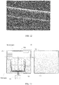
- the carbon nanotube layer may include a plurality of carbon nanotube wires. Referring to FIG. 8 , a plurality of carbon nanotube wires 16 can be crossed with each other to form the carbon nanotube layer. Referring to FIG.9 , a plurality of carbon nanotube wires 16 can be waved with each other to form the carbon nanotube layer. In other embodiments, the carbon nanotube layer may include only one carbon nanotube wire. Referring to FIG. 10 , one carbon nanotube wire 16 can be bended to form the carbon nanotube layer.
- the carbon nanotube wire can be untwisted or twisted.
- an untwisted carbon nanotube wire includes a plurality of carbon nanotubes substantially oriented along a same direction (i.e., a direction along the length direction of the untwisted carbon nanotube wire).
- the untwisted carbon nanotube wire can be a pure structure of carbon nanotubes.
- the untwisted carbon nanotube wire can be a freestanding structure.
- the carbon nanotubes are substantially parallel to the axis of the untwisted carbon nanotube wire.
- the untwisted carbon nanotube wire may include a plurality of successive carbon nanotube segments joined end to end by van der Waals attractive force therebetween.
- Each carbon nanotube segment may include a plurality of carbon nanotubes substantially parallel to each other, and combined by van der Waals attractive force therebetween.
- the carbon nanotube segments can vary in width, thickness, uniformity, and shape.
- the length of the untwisted carbon nanotube wire can be arbitrarily set as desired.
- a diameter of the untwisted carbon nanotube wire may range from about 50 nanometers to about 100 micrometers.
- a twisted carbon nanotube wire may include a plurality of carbon nanotubes helically oriented around an axial direction of the twisted carbon nanotube wire.
- the twisted carbon nanotube wire can be a pure structure of carbon nanotubes.
- the twisted carbon nanotube wire can be a freestanding structure.
- the twisted carbon nanotube wire may include a plurality of successive carbon nanotube segments joined end to end by van der Waals attractive force therebetween.
- Each carbon nanotube segment may include a plurality of carbon nanotubes substantially parallel to each other, and combined by van der Waals attractive force therebetween.
- the length of the carbon nanotube wire can be set as desired.
- a diameter of the twisted carbon nanotube wire may range from about 50 nanometers to about 100 micrometers.
- the twisted carbon nanotube wire can be treated with a volatile organic solvent after being twisted. After being soaked by the organic solvent, the adjacent substantially parallel carbon nanotubes in the twisted carbon nanotube wire will bundle together, due to a surskin tension of the organic solvent when the organic solvent volatilizes. The density and strength of the twisted carbon nanotube wire will increase.
- the carbon nanotube layer has a better flexibility than the first flexible layer 102 and/or the second flexible layer 106.
- the flexibility of the entire flexible sheet 100 is not decreased by the functional layer 104.
- the carbon nanotube layer has a large strength, as such, no matter how the flexible sheet 100 is bent or pulled, and the carbon nanotube layer is not damaged.
- each of the plurality of functional layer 104 can further comprise a graphene layer.
- the graphene layer includes at least one graphene.
- the graphene layer is a pure structure of graphenes.
- the graphene layer structure can include a single graphene or a plurality of graphenes.
- the graphene layer includes a plurality of graphenes, the plurality of graphenes is stacked with each other and/or located side by side. The plurality of graphenes is combined with each other by van der Waals attractive force.
- the graphene layer can be a continuous integrated structure.
- the soft physiotherapy instrument 20 comprises a flexible sheet (not labeled) and a controller 212.
- the flexible sheet includes a first flexible layer 202 and a second flexible layer 206, the first flexible layer 202 and the second flexible layer 206 are stacked with each other.
- the flexible sheet further includes a plurality of functional layers 204 sandwiched between the first flexible layer 202 and the second flexible layer 206 and a plurality of electrodes 208 electrically connected with the plurality of functional layers 204.
- the plurality of functional layers 204 includes a plurality of first functional layers 204a located in a first region and a plurality of second functional layers 204b located in a second region.
- Each of the plurality of electrodes 208 is electrically connected with a pair of first functional layers 204a, and is electrically connected with a second functional layer 204b.
- the plurality of functional layers 204 includes ten first functional layers 204a symmetrically distributed in the first region, and include three functional layers 204b in the second region.
- the ten first functional layers 204b include five pairs of first functional layers 204b, and each pair of first functional 204b is numbered 1, 2, 3, 4 and 5 in order from top to bottom of the flexible sheet.
- the electrodes electrically connected with the five pairs of first functional layers 204a is numbered 1, 2, 3, 4 and 5, which is the same as the number of the first functional layers 204a.
- the three second functional layers 204b are electrically connected with the three electrodes numbered 1, 3 and 5. That is, a difference of the number x and y of the adjacent second functional layers 204b is 2.
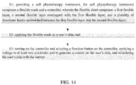
- the present disclosure further provides a method of using a soft physiotherapy instrument, the method comprises the steps of:
- the soft physiotherapy instrument is any one of the soft physiotherapy instruments 10, 20 and 30 discussed above.
- the controller includes a plurality of function buttons for controlling the flexible sheet.
- Each of the plurality of function buttons is used to control the functional layer inside the flexible sheet to achieve the stimulating function.
- Each of the plurality of function buttons can be configured to control a current magnitude, a current frequency, a position of the functional layer which the current is input.
- the voltage applied on each two electrodes can be kept for a power-on time, and the voltage is stop for a dwell time, then the voltage is applied to another two electrodes for another power-on time and another dwell time.
- step S3 the voltage is applied between the two electrodes in cycles of 1 and 2, 2 and 3, 3 and 4... K-1 and K, so as to circulate the two pairs of first functional layers corresponding to each two electrodes.
- a loop is formed between the controller, the two electrodes, two pairs of first functional layers, the skin of the user between the two first functional layers on one side, the skin of the user between the two first functional layers on the other side.
- a current is generated in the loop, as such, the skin of the user between the two first functional layers on one side and the skin of the user between the two first functional layers on the other side in the first region are stimulated.
- the two electrodes 108 with two neighbor number, e,g., K-1 and K are connected with the two pairs of first functional layer 104a with two neighbor number, e,g., K-1 and K. And there is no other functional layer 104a located between the adjacent functional layers on the same side.
- the user's skin located between the adjacent functional layers is stimulated. In this way, by sequentially or selectively applying voltage to the two electrodes 108 with adjacent numbers, the purpose of sequentially or selectively stimulating the skin of the user at different positions in the first region can be achieved.
- the controller can also input a voltage between two electrodes that are not adjacent in number.
- the two pairs of first function layers corresponding to the two electrodes comprises two first functional layers on the same side separated with each other.
- the two first functional layers on the same side is separated by at least one first functional layer on the same side of the flexible sheet.
- the controller chooses to apply a voltage between two electrodes that are not adjacent to the number, it will not stimulate the skin between the first functional layers in the first region, but it can stimulate the skin between the second functional layers in the second region.
- the electrodes 108 are energized according to the circulation pattern of the electrodes numbered 1 and 2, 2 and 3, and 3 and 4, thereby sequentially or selectively generating micro-currents in the two pairs of first functional layers, which in turn stimulate the skin in the first region.
- the power-on time of each pair of electrodes 108 is 1 s and the dwell time is 1 s. That is, with a cycle of 2 s, the power is first applied for 1 s, and then stopped for 1 s, and this cycle is performed.
- the voltage applied on each two electrodes is in a range of 20V-36V and the frequency of the voltage is 90Khz.
- the soft physiotherapy instrument Compared with the prior art, the soft physiotherapy instrument provided by the present invention has the following advantages: first, it can directly fit on a user's skin without the need to hold it by hand, which frees the user's hands. Secondly, through controlling a circuit by the controller, the skin on the user's skin can be selectively stimulated, and the skin parts to be stimulated can be selected more accurately without causing facial asymmetry. Third, the carbon nanotube layer is used as the functional layer, the carbon nanotube layer has a better flexibility than the first flexible layer or / and the second flexible layer, and the flexibility of the entire flexible sheet will not be reduced due to the setting of the functional layers, the flexible sheet can fit on the user's skin well, and the user has a high comfort degree. Fourth, the carbon nanotube layer is used as a functional layer, a strength of the carbon nanotube layer is relatively large, no matter how to bend and pull or clean the flexible sheet, the carbon nanotube layer will not be damaged, and the flexible sheet has a long life.
Landscapes
- Health & Medical Sciences (AREA)
- Life Sciences & Earth Sciences (AREA)
- Public Health (AREA)
- Veterinary Medicine (AREA)
- Radiology & Medical Imaging (AREA)
- Biomedical Technology (AREA)
- Animal Behavior & Ethology (AREA)
- General Health & Medical Sciences (AREA)
- Engineering & Computer Science (AREA)
- Nuclear Medicine, Radiotherapy & Molecular Imaging (AREA)
- Biophysics (AREA)
- Heart & Thoracic Surgery (AREA)
- Oral & Maxillofacial Surgery (AREA)
- Plastic & Reconstructive Surgery (AREA)
- Electrotherapy Devices (AREA)
- Pharmaceuticals Containing Other Organic And Inorganic Compounds (AREA)
- Materials For Medical Uses (AREA)
Applications Claiming Priority (2)
| Application Number | Priority Date | Filing Date | Title |
|---|---|---|---|
| CN202010043624.7A CN113117231B (zh) | 2020-01-15 | 2020-01-15 | 贴敷式理疗仪 |
| CN202010044331.0A CN113117233B (zh) | 2020-01-15 | 2020-01-15 | 贴敷式理疗仪的使用方法 |
Publications (2)
| Publication Number | Publication Date |
|---|---|
| EP3851157A1 true EP3851157A1 (fr) | 2021-07-21 |
| EP3851157B1 EP3851157B1 (fr) | 2023-06-28 |
Family
ID=73597778
Family Applications (1)
| Application Number | Title | Priority Date | Filing Date |
|---|---|---|---|
| EP20209517.0A Active EP3851157B1 (fr) | 2020-01-15 | 2020-11-24 | Instrument de physiothérapie douce et son procédé d'utilisation |
Country Status (5)
| Country | Link |
|---|---|
| EP (1) | EP3851157B1 (fr) |
| JP (1) | JP7159280B2 (fr) |
| KR (1) | KR102590089B1 (fr) |
| ES (1) | ES2951418T3 (fr) |
| FI (1) | FI3851157T3 (fr) |
Families Citing this family (3)
| Publication number | Priority date | Publication date | Assignee | Title |
|---|---|---|---|---|
| CN118356577A (zh) * | 2023-01-17 | 2024-07-19 | 北京富纳特创新科技有限公司 | 3d面膜式美容仪及其工作方法 |
| CN118356578A (zh) * | 2023-01-17 | 2024-07-19 | 北京富纳特创新科技有限公司 | 3d贴敷式理疗仪及其工作方法 |
| KR20250000979U (ko) | 2023-12-18 | 2025-06-25 | 풍림전자 주식회사 | 미세전류 자극기 |
Citations (5)
| Publication number | Priority date | Publication date | Assignee | Title |
|---|---|---|---|---|
| WO2016016015A1 (fr) * | 2014-07-29 | 2016-02-04 | L'oreal | Masque électrique souple multi-électrode |
| CN107260390A (zh) * | 2017-07-17 | 2017-10-20 | 苏州捷迪纳米科技有限公司 | 一种美容面罩及其制备方法 |
| US20180099143A1 (en) * | 2016-10-06 | 2018-04-12 | Lg Electronics Inc. | Skin care device |
| CN208838309U (zh) * | 2018-03-20 | 2019-05-10 | 苏州捷迪纳米科技有限公司 | 一种柔性加热面罩 |
| EP3804668A1 (fr) * | 2019-10-11 | 2021-04-14 | Beijing Funate Innovation Technology Co., Ltd. | Instrument de beauté doté d'un masque et instrument de physiothérapie douce |
Family Cites Families (6)
| Publication number | Priority date | Publication date | Assignee | Title |
|---|---|---|---|---|
| FI106364B (fi) * | 1999-06-21 | 2001-01-31 | Lehtoluoto Eeva Liisa | Ihonpuhdistuslaite |
| GB0603464D0 (en) * | 2006-02-21 | 2006-04-05 | Goreszeniuk Teodor | Improvements in & relating to external neurostimulation |
| CN106456964A (zh) * | 2014-02-04 | 2017-02-22 | 莱雅公司 | 包括至少两个隔室的电面膜 |
| JP2017108758A (ja) * | 2015-12-14 | 2017-06-22 | パナソニックIpマネジメント株式会社 | 生体用電気刺激デバイスと生体用電気刺激装置 |
| CN206275917U (zh) * | 2016-06-07 | 2017-06-27 | 广州三得医疗科技有限公司 | 用于疼痛康复治疗或预防的可贴覆面部低频理疗面膜 |
| JP2018183480A (ja) * | 2017-04-27 | 2018-11-22 | 株式会社 Mtg | 筋肉電気刺激装置 |
-
2020
- 2020-11-24 FI FIEP20209517.0T patent/FI3851157T3/fi active
- 2020-11-24 EP EP20209517.0A patent/EP3851157B1/fr active Active
- 2020-11-24 ES ES20209517T patent/ES2951418T3/es active Active
- 2020-12-08 KR KR1020200170881A patent/KR102590089B1/ko active Active
- 2020-12-25 JP JP2020217519A patent/JP7159280B2/ja active Active
Patent Citations (5)
| Publication number | Priority date | Publication date | Assignee | Title |
|---|---|---|---|---|
| WO2016016015A1 (fr) * | 2014-07-29 | 2016-02-04 | L'oreal | Masque électrique souple multi-électrode |
| US20180099143A1 (en) * | 2016-10-06 | 2018-04-12 | Lg Electronics Inc. | Skin care device |
| CN107260390A (zh) * | 2017-07-17 | 2017-10-20 | 苏州捷迪纳米科技有限公司 | 一种美容面罩及其制备方法 |
| CN208838309U (zh) * | 2018-03-20 | 2019-05-10 | 苏州捷迪纳米科技有限公司 | 一种柔性加热面罩 |
| EP3804668A1 (fr) * | 2019-10-11 | 2021-04-14 | Beijing Funate Innovation Technology Co., Ltd. | Instrument de beauté doté d'un masque et instrument de physiothérapie douce |
Also Published As
| Publication number | Publication date |
|---|---|
| KR102590089B1 (ko) | 2023-10-16 |
| JP7159280B2 (ja) | 2022-10-24 |
| EP3851157B1 (fr) | 2023-06-28 |
| FI3851157T3 (fi) | 2023-07-26 |
| ES2951418T3 (es) | 2023-10-20 |
| KR20210092668A (ko) | 2021-07-26 |
| JP2021109100A (ja) | 2021-08-02 |
Similar Documents
| Publication | Publication Date | Title |
|---|---|---|
| US11413448B2 (en) | Soft physiotherapy instrument and method for using the same | |
| EP3851157B1 (fr) | Instrument de physiothérapie douce et son procédé d'utilisation | |
| US11577070B2 (en) | Soft physiotherapy instrument | |
| US11229791B2 (en) | Beauty instrument with mask | |
| US11589668B2 (en) | Beauty instrument with mask | |
| US11260217B2 (en) | Mask-type beauty instrument | |
| US11504522B2 (en) | Method for using mask-type beauty instrument | |
| EP3851156B1 (fr) | Instrument de beauté de type masque | |
| US12220574B2 (en) | Mask instrument and method for using the same | |
| EP3804668B1 (fr) | Instrument de beauté doté d'un masque et instrument de physiothérapie douce | |
| US11413447B2 (en) | Method for using beauty instrument with mask | |
| US20210106460A1 (en) | Method for using beauty instrument with mask | |
| US20210106119A1 (en) | Beauty instrument with mask | |
| US11464974B2 (en) | Method for using soft physiotherapy instrument | |
| US20230027020A1 (en) | Physiotherapy sheet and method for using the same | |
| US11529512B2 (en) | Method for using beauty instrument with mask |
Legal Events
| Date | Code | Title | Description |
|---|---|---|---|
| PUAI | Public reference made under article 153(3) epc to a published international application that has entered the european phase |
Free format text: ORIGINAL CODE: 0009012 |
|
| STAA | Information on the status of an ep patent application or granted ep patent |
Free format text: STATUS: THE APPLICATION HAS BEEN PUBLISHED |
|
| AK | Designated contracting states |
Kind code of ref document: A1 Designated state(s): AL AT BE BG CH CY CZ DE DK EE ES FI FR GB GR HR HU IE IS IT LI LT LU LV MC MK MT NL NO PL PT RO RS SE SI SK SM TR |
|
| STAA | Information on the status of an ep patent application or granted ep patent |
Free format text: STATUS: REQUEST FOR EXAMINATION WAS MADE |
|
| 17P | Request for examination filed |
Effective date: 20210820 |
|
| RBV | Designated contracting states (corrected) |
Designated state(s): AL AT BE BG CH CY CZ DE DK EE ES FI FR GB GR HR HU IE IS IT LI LT LU LV MC MK MT NL NO PL PT RO RS SE SI SK SM TR |
|
| GRAP | Despatch of communication of intention to grant a patent |
Free format text: ORIGINAL CODE: EPIDOSNIGR1 |
|
| STAA | Information on the status of an ep patent application or granted ep patent |
Free format text: STATUS: GRANT OF PATENT IS INTENDED |
|
| RIC1 | Information provided on ipc code assigned before grant |
Ipc: A61N 1/32 20060101ALN20230214BHEP Ipc: A61N 1/20 20060101ALN20230214BHEP Ipc: A45D 44/00 20060101ALI20230214BHEP Ipc: A61F 7/02 20060101ALI20230214BHEP Ipc: A61F 7/00 20060101ALI20230214BHEP Ipc: A61N 1/36 20060101ALI20230214BHEP Ipc: A61N 1/04 20060101AFI20230214BHEP |
|
| INTG | Intention to grant announced |
Effective date: 20230313 |
|
| GRAS | Grant fee paid |
Free format text: ORIGINAL CODE: EPIDOSNIGR3 |
|
| GRAA | (expected) grant |
Free format text: ORIGINAL CODE: 0009210 |
|
| STAA | Information on the status of an ep patent application or granted ep patent |
Free format text: STATUS: THE PATENT HAS BEEN GRANTED |
|
| AK | Designated contracting states |
Kind code of ref document: B1 Designated state(s): AL AT BE BG CH CY CZ DE DK EE ES FI FR GB GR HR HU IE IS IT LI LT LU LV MC MK MT NL NO PL PT RO RS SE SI SK SM TR |
|
| REG | Reference to a national code |
Ref country code: CH Ref legal event code: EP |
|
| P01 | Opt-out of the competence of the unified patent court (upc) registered |
Effective date: 20230526 |
|
| REG | Reference to a national code |
Ref country code: AT Ref legal event code: REF Ref document number: 1582176 Country of ref document: AT Kind code of ref document: T Effective date: 20230715 |
|
| REG | Reference to a national code |
Ref country code: IE Ref legal event code: FG4D |
|
| REG | Reference to a national code |
Ref country code: DE Ref legal event code: R096 Ref document number: 602020012976 Country of ref document: DE |
|
| REG | Reference to a national code |
Ref country code: FI Ref legal event code: FGE |
|
| REG | Reference to a national code |
Ref country code: NL Ref legal event code: FP |
|
| REG | Reference to a national code |
Ref country code: LT Ref legal event code: MG9D |
|
| REG | Reference to a national code |
Ref country code: ES Ref legal event code: FG2A Ref document number: 2951418 Country of ref document: ES Kind code of ref document: T3 Effective date: 20231020 |
|
| PG25 | Lapsed in a contracting state [announced via postgrant information from national office to epo] |
Ref country code: SE Free format text: LAPSE BECAUSE OF FAILURE TO SUBMIT A TRANSLATION OF THE DESCRIPTION OR TO PAY THE FEE WITHIN THE PRESCRIBED TIME-LIMIT Effective date: 20230628 Ref country code: NO Free format text: LAPSE BECAUSE OF FAILURE TO SUBMIT A TRANSLATION OF THE DESCRIPTION OR TO PAY THE FEE WITHIN THE PRESCRIBED TIME-LIMIT Effective date: 20230928 |
|
| REG | Reference to a national code |
Ref country code: AT Ref legal event code: MK05 Ref document number: 1582176 Country of ref document: AT Kind code of ref document: T Effective date: 20230628 |
|
| PG25 | Lapsed in a contracting state [announced via postgrant information from national office to epo] |
Ref country code: RS Free format text: LAPSE BECAUSE OF FAILURE TO SUBMIT A TRANSLATION OF THE DESCRIPTION OR TO PAY THE FEE WITHIN THE PRESCRIBED TIME-LIMIT Effective date: 20230628 Ref country code: LV Free format text: LAPSE BECAUSE OF FAILURE TO SUBMIT A TRANSLATION OF THE DESCRIPTION OR TO PAY THE FEE WITHIN THE PRESCRIBED TIME-LIMIT Effective date: 20230628 Ref country code: LT Free format text: LAPSE BECAUSE OF FAILURE TO SUBMIT A TRANSLATION OF THE DESCRIPTION OR TO PAY THE FEE WITHIN THE PRESCRIBED TIME-LIMIT Effective date: 20230628 Ref country code: HR Free format text: LAPSE BECAUSE OF FAILURE TO SUBMIT A TRANSLATION OF THE DESCRIPTION OR TO PAY THE FEE WITHIN THE PRESCRIBED TIME-LIMIT Effective date: 20230628 Ref country code: GR Free format text: LAPSE BECAUSE OF FAILURE TO SUBMIT A TRANSLATION OF THE DESCRIPTION OR TO PAY THE FEE WITHIN THE PRESCRIBED TIME-LIMIT Effective date: 20230929 |
|
| PG25 | Lapsed in a contracting state [announced via postgrant information from national office to epo] |
Ref country code: SK Free format text: LAPSE BECAUSE OF FAILURE TO SUBMIT A TRANSLATION OF THE DESCRIPTION OR TO PAY THE FEE WITHIN THE PRESCRIBED TIME-LIMIT Effective date: 20230628 |
|
| PG25 | Lapsed in a contracting state [announced via postgrant information from national office to epo] |
Ref country code: IS Free format text: LAPSE BECAUSE OF FAILURE TO SUBMIT A TRANSLATION OF THE DESCRIPTION OR TO PAY THE FEE WITHIN THE PRESCRIBED TIME-LIMIT Effective date: 20231028 |
|
| PG25 | Lapsed in a contracting state [announced via postgrant information from national office to epo] |
Ref country code: SM Free format text: LAPSE BECAUSE OF FAILURE TO SUBMIT A TRANSLATION OF THE DESCRIPTION OR TO PAY THE FEE WITHIN THE PRESCRIBED TIME-LIMIT Effective date: 20230628 Ref country code: SK Free format text: LAPSE BECAUSE OF FAILURE TO SUBMIT A TRANSLATION OF THE DESCRIPTION OR TO PAY THE FEE WITHIN THE PRESCRIBED TIME-LIMIT Effective date: 20230628 Ref country code: RO Free format text: LAPSE BECAUSE OF FAILURE TO SUBMIT A TRANSLATION OF THE DESCRIPTION OR TO PAY THE FEE WITHIN THE PRESCRIBED TIME-LIMIT Effective date: 20230628 Ref country code: PT Free format text: LAPSE BECAUSE OF FAILURE TO SUBMIT A TRANSLATION OF THE DESCRIPTION OR TO PAY THE FEE WITHIN THE PRESCRIBED TIME-LIMIT Effective date: 20231030 Ref country code: IS Free format text: LAPSE BECAUSE OF FAILURE TO SUBMIT A TRANSLATION OF THE DESCRIPTION OR TO PAY THE FEE WITHIN THE PRESCRIBED TIME-LIMIT Effective date: 20231028 Ref country code: EE Free format text: LAPSE BECAUSE OF FAILURE TO SUBMIT A TRANSLATION OF THE DESCRIPTION OR TO PAY THE FEE WITHIN THE PRESCRIBED TIME-LIMIT Effective date: 20230628 Ref country code: CZ Free format text: LAPSE BECAUSE OF FAILURE TO SUBMIT A TRANSLATION OF THE DESCRIPTION OR TO PAY THE FEE WITHIN THE PRESCRIBED TIME-LIMIT Effective date: 20230628 Ref country code: AT Free format text: LAPSE BECAUSE OF FAILURE TO SUBMIT A TRANSLATION OF THE DESCRIPTION OR TO PAY THE FEE WITHIN THE PRESCRIBED TIME-LIMIT Effective date: 20230628 |
|
| PG25 | Lapsed in a contracting state [announced via postgrant information from national office to epo] |
Ref country code: PL Free format text: LAPSE BECAUSE OF FAILURE TO SUBMIT A TRANSLATION OF THE DESCRIPTION OR TO PAY THE FEE WITHIN THE PRESCRIBED TIME-LIMIT Effective date: 20230628 |
|
| REG | Reference to a national code |
Ref country code: DE Ref legal event code: R097 Ref document number: 602020012976 Country of ref document: DE |
|
| PG25 | Lapsed in a contracting state [announced via postgrant information from national office to epo] |
Ref country code: DK Free format text: LAPSE BECAUSE OF FAILURE TO SUBMIT A TRANSLATION OF THE DESCRIPTION OR TO PAY THE FEE WITHIN THE PRESCRIBED TIME-LIMIT Effective date: 20230628 |
|
| PLBE | No opposition filed within time limit |
Free format text: ORIGINAL CODE: 0009261 |
|
| STAA | Information on the status of an ep patent application or granted ep patent |
Free format text: STATUS: NO OPPOSITION FILED WITHIN TIME LIMIT |
|
| 26N | No opposition filed |
Effective date: 20240402 |
|
| REG | Reference to a national code |
Ref country code: CH Ref legal event code: PL |
|
| PG25 | Lapsed in a contracting state [announced via postgrant information from national office to epo] |
Ref country code: MC Free format text: LAPSE BECAUSE OF FAILURE TO SUBMIT A TRANSLATION OF THE DESCRIPTION OR TO PAY THE FEE WITHIN THE PRESCRIBED TIME-LIMIT Effective date: 20230628 |
|
| PG25 | Lapsed in a contracting state [announced via postgrant information from national office to epo] |
Ref country code: LU Free format text: LAPSE BECAUSE OF NON-PAYMENT OF DUE FEES Effective date: 20231124 |
|
| PG25 | Lapsed in a contracting state [announced via postgrant information from national office to epo] |
Ref country code: CH Free format text: LAPSE BECAUSE OF NON-PAYMENT OF DUE FEES Effective date: 20231130 |
|
| PG25 | Lapsed in a contracting state [announced via postgrant information from national office to epo] |
Ref country code: MC Free format text: LAPSE BECAUSE OF FAILURE TO SUBMIT A TRANSLATION OF THE DESCRIPTION OR TO PAY THE FEE WITHIN THE PRESCRIBED TIME-LIMIT Effective date: 20230628 Ref country code: LU Free format text: LAPSE BECAUSE OF NON-PAYMENT OF DUE FEES Effective date: 20231124 Ref country code: CH Free format text: LAPSE BECAUSE OF NON-PAYMENT OF DUE FEES Effective date: 20231130 Ref country code: SI Free format text: LAPSE BECAUSE OF FAILURE TO SUBMIT A TRANSLATION OF THE DESCRIPTION OR TO PAY THE FEE WITHIN THE PRESCRIBED TIME-LIMIT Effective date: 20230628 |
|
| REG | Reference to a national code |
Ref country code: BE Ref legal event code: MM Effective date: 20231130 |
|
| REG | Reference to a national code |
Ref country code: IE Ref legal event code: MM4A |
|
| PG25 | Lapsed in a contracting state [announced via postgrant information from national office to epo] |
Ref country code: IE Free format text: LAPSE BECAUSE OF NON-PAYMENT OF DUE FEES Effective date: 20231124 |
|
| PG25 | Lapsed in a contracting state [announced via postgrant information from national office to epo] |
Ref country code: BE Free format text: LAPSE BECAUSE OF NON-PAYMENT OF DUE FEES Effective date: 20231130 |
|
| PG25 | Lapsed in a contracting state [announced via postgrant information from national office to epo] |
Ref country code: IE Free format text: LAPSE BECAUSE OF NON-PAYMENT OF DUE FEES Effective date: 20231124 Ref country code: BE Free format text: LAPSE BECAUSE OF NON-PAYMENT OF DUE FEES Effective date: 20231130 |
|
| PG25 | Lapsed in a contracting state [announced via postgrant information from national office to epo] |
Ref country code: BG Free format text: LAPSE BECAUSE OF FAILURE TO SUBMIT A TRANSLATION OF THE DESCRIPTION OR TO PAY THE FEE WITHIN THE PRESCRIBED TIME-LIMIT Effective date: 20230628 |
|
| PG25 | Lapsed in a contracting state [announced via postgrant information from national office to epo] |
Ref country code: BG Free format text: LAPSE BECAUSE OF FAILURE TO SUBMIT A TRANSLATION OF THE DESCRIPTION OR TO PAY THE FEE WITHIN THE PRESCRIBED TIME-LIMIT Effective date: 20230628 |
|
| PG25 | Lapsed in a contracting state [announced via postgrant information from national office to epo] |
Ref country code: CY Free format text: LAPSE BECAUSE OF FAILURE TO SUBMIT A TRANSLATION OF THE DESCRIPTION OR TO PAY THE FEE WITHIN THE PRESCRIBED TIME-LIMIT; INVALID AB INITIO Effective date: 20201124 |
|
| PG25 | Lapsed in a contracting state [announced via postgrant information from national office to epo] |
Ref country code: HU Free format text: LAPSE BECAUSE OF FAILURE TO SUBMIT A TRANSLATION OF THE DESCRIPTION OR TO PAY THE FEE WITHIN THE PRESCRIBED TIME-LIMIT; INVALID AB INITIO Effective date: 20201124 |
|
| PG25 | Lapsed in a contracting state [announced via postgrant information from national office to epo] |
Ref country code: TR Free format text: LAPSE BECAUSE OF FAILURE TO SUBMIT A TRANSLATION OF THE DESCRIPTION OR TO PAY THE FEE WITHIN THE PRESCRIBED TIME-LIMIT Effective date: 20230628 |
|
| PGFP | Annual fee paid to national office [announced via postgrant information from national office to epo] |
Ref country code: NL Payment date: 20251127 Year of fee payment: 6 |
|
| PGFP | Annual fee paid to national office [announced via postgrant information from national office to epo] |
Ref country code: GB Payment date: 20251226 Year of fee payment: 6 |
|
| PGFP | Annual fee paid to national office [announced via postgrant information from national office to epo] |
Ref country code: IT Payment date: 20251106 Year of fee payment: 6 Ref country code: FI Payment date: 20251124 Year of fee payment: 6 |
|
| PGFP | Annual fee paid to national office [announced via postgrant information from national office to epo] |
Ref country code: FR Payment date: 20251128 Year of fee payment: 6 |
|
| PGFP | Annual fee paid to national office [announced via postgrant information from national office to epo] |
Ref country code: ES Payment date: 20251212 Year of fee payment: 6 |
|
| PGFP | Annual fee paid to national office [announced via postgrant information from national office to epo] |
Ref country code: DE Payment date: 20251231 Year of fee payment: 6 |