EP3851271A1 - Procédé et dispositif de fabrication de pièces tubulaires individuelles, ainsi que pièces tubulaires et sacs - Google Patents
Procédé et dispositif de fabrication de pièces tubulaires individuelles, ainsi que pièces tubulaires et sacs Download PDFInfo
- Publication number
- EP3851271A1 EP3851271A1 EP21020009.3A EP21020009A EP3851271A1 EP 3851271 A1 EP3851271 A1 EP 3851271A1 EP 21020009 A EP21020009 A EP 21020009A EP 3851271 A1 EP3851271 A1 EP 3851271A1
- Authority
- EP
- European Patent Office
- Prior art keywords
- hose
- folded edge
- tube
- front wall
- rear wall
- Prior art date
- Legal status (The legal status is an assumption and is not a legal conclusion. Google has not performed a legal analysis and makes no representation as to the accuracy of the status listed.)
- Pending
Links
- 238000004519 manufacturing process Methods 0.000 title claims abstract description 17
- 238000000034 method Methods 0.000 title claims description 15
- 239000000853 adhesive Substances 0.000 claims abstract description 33
- 230000001070 adhesive effect Effects 0.000 claims abstract description 33
- 238000000926 separation method Methods 0.000 claims abstract description 4
- 239000003292 glue Substances 0.000 claims description 45
- 239000000463 material Substances 0.000 claims description 29
- 238000004049 embossing Methods 0.000 claims description 11
- 239000011344 liquid material Substances 0.000 claims description 2
- 239000007788 liquid Substances 0.000 description 7
- 238000004026 adhesive bonding Methods 0.000 description 5
- 230000015572 biosynthetic process Effects 0.000 description 2
- 239000012459 cleaning agent Substances 0.000 description 2
- 238000001816 cooling Methods 0.000 description 2
- 238000005520 cutting process Methods 0.000 description 2
- 238000001035 drying Methods 0.000 description 2
- 239000012943 hotmelt Substances 0.000 description 2
- 239000004033 plastic Substances 0.000 description 2
- 229920002472 Starch Polymers 0.000 description 1
- 230000004888 barrier function Effects 0.000 description 1
- 230000001419 dependent effect Effects 0.000 description 1
- 239000000428 dust Substances 0.000 description 1
- 230000002093 peripheral effect Effects 0.000 description 1
- 239000002985 plastic film Substances 0.000 description 1
- 230000002787 reinforcement Effects 0.000 description 1
- 239000011265 semifinished product Substances 0.000 description 1
- 235000019698 starch Nutrition 0.000 description 1
- 239000008107 starch Substances 0.000 description 1
- 239000000126 substance Substances 0.000 description 1
- 230000008961 swelling Effects 0.000 description 1
- XLYOFNOQVPJJNP-UHFFFAOYSA-N water Substances O XLYOFNOQVPJJNP-UHFFFAOYSA-N 0.000 description 1
Images

Classifications
-
- B—PERFORMING OPERATIONS; TRANSPORTING
- B31—MAKING ARTICLES OF PAPER, CARDBOARD OR MATERIAL WORKED IN A MANNER ANALOGOUS TO PAPER; WORKING PAPER, CARDBOARD OR MATERIAL WORKED IN A MANNER ANALOGOUS TO PAPER
- B31B—MAKING CONTAINERS OF PAPER, CARDBOARD OR MATERIAL WORKED IN A MANNER ANALOGOUS TO PAPER
- B31B70/00—Making flexible containers, e.g. envelopes or bags
- B31B70/008—Stiffening or reinforcing
-
- B—PERFORMING OPERATIONS; TRANSPORTING
- B31—MAKING ARTICLES OF PAPER, CARDBOARD OR MATERIAL WORKED IN A MANNER ANALOGOUS TO PAPER; WORKING PAPER, CARDBOARD OR MATERIAL WORKED IN A MANNER ANALOGOUS TO PAPER
- B31B—MAKING CONTAINERS OF PAPER, CARDBOARD OR MATERIAL WORKED IN A MANNER ANALOGOUS TO PAPER
- B31B2155/00—Flexible containers made from webs
- B31B2155/002—Flexible containers made from webs by joining superimposed webs, e.g. with separate bottom webs
-
- B—PERFORMING OPERATIONS; TRANSPORTING
- B31—MAKING ARTICLES OF PAPER, CARDBOARD OR MATERIAL WORKED IN A MANNER ANALOGOUS TO PAPER; WORKING PAPER, CARDBOARD OR MATERIAL WORKED IN A MANNER ANALOGOUS TO PAPER
- B31B—MAKING CONTAINERS OF PAPER, CARDBOARD OR MATERIAL WORKED IN A MANNER ANALOGOUS TO PAPER
- B31B2170/00—Construction of flexible containers
- B31B2170/20—Construction of flexible containers having multi-layered walls, e.g. laminated or lined
-
- B—PERFORMING OPERATIONS; TRANSPORTING
- B31—MAKING ARTICLES OF PAPER, CARDBOARD OR MATERIAL WORKED IN A MANNER ANALOGOUS TO PAPER; WORKING PAPER, CARDBOARD OR MATERIAL WORKED IN A MANNER ANALOGOUS TO PAPER
- B31B—MAKING CONTAINERS OF PAPER, CARDBOARD OR MATERIAL WORKED IN A MANNER ANALOGOUS TO PAPER
- B31B70/00—Making flexible containers, e.g. envelopes or bags
- B31B70/14—Cutting, e.g. perforating, punching, slitting or trimming
-
- B—PERFORMING OPERATIONS; TRANSPORTING
- B31—MAKING ARTICLES OF PAPER, CARDBOARD OR MATERIAL WORKED IN A MANNER ANALOGOUS TO PAPER; WORKING PAPER, CARDBOARD OR MATERIAL WORKED IN A MANNER ANALOGOUS TO PAPER
- B31B—MAKING CONTAINERS OF PAPER, CARDBOARD OR MATERIAL WORKED IN A MANNER ANALOGOUS TO PAPER
- B31B70/00—Making flexible containers, e.g. envelopes or bags
- B31B70/26—Folding sheets, blanks or webs
- B31B70/262—Folding sheets, blanks or webs involving longitudinally folding, i.e. along a line parallel to the direction of movement
-
- B—PERFORMING OPERATIONS; TRANSPORTING
- B31—MAKING ARTICLES OF PAPER, CARDBOARD OR MATERIAL WORKED IN A MANNER ANALOGOUS TO PAPER; WORKING PAPER, CARDBOARD OR MATERIAL WORKED IN A MANNER ANALOGOUS TO PAPER
- B31B—MAKING CONTAINERS OF PAPER, CARDBOARD OR MATERIAL WORKED IN A MANNER ANALOGOUS TO PAPER
- B31B70/00—Making flexible containers, e.g. envelopes or bags
- B31B70/26—Folding sheets, blanks or webs
- B31B70/36—Folding sheets, blanks or webs by continuously feeding them to stationary members, e.g. plates, ploughs or cores
-
- B—PERFORMING OPERATIONS; TRANSPORTING
- B31—MAKING ARTICLES OF PAPER, CARDBOARD OR MATERIAL WORKED IN A MANNER ANALOGOUS TO PAPER; WORKING PAPER, CARDBOARD OR MATERIAL WORKED IN A MANNER ANALOGOUS TO PAPER
- B31B—MAKING CONTAINERS OF PAPER, CARDBOARD OR MATERIAL WORKED IN A MANNER ANALOGOUS TO PAPER
- B31B70/00—Making flexible containers, e.g. envelopes or bags
- B31B70/60—Uniting opposed surfaces or edges; Taping
- B31B70/62—Uniting opposed surfaces or edges; Taping by adhesives
- B31B70/628—Applying glue on moving webs to form tubular webs
-
- B—PERFORMING OPERATIONS; TRANSPORTING
- B31—MAKING ARTICLES OF PAPER, CARDBOARD OR MATERIAL WORKED IN A MANNER ANALOGOUS TO PAPER; WORKING PAPER, CARDBOARD OR MATERIAL WORKED IN A MANNER ANALOGOUS TO PAPER
- B31B—MAKING CONTAINERS OF PAPER, CARDBOARD OR MATERIAL WORKED IN A MANNER ANALOGOUS TO PAPER
- B31B70/00—Making flexible containers, e.g. envelopes or bags
- B31B70/74—Auxiliary operations
- B31B70/88—Printing; Embossing
Definitions
- the invention relates to a method and device for producing individual pieces of tubing, as well as pieces of tubing and sacks which comprise such pieces of tubing.
- a tube is usually first produced from a flat web, which comprises paper, by turning over the side areas.
- the fold-over is carried out in such a way that the turned-over side areas overlap along an overlap area.
- a sticky substance for example in glue, in particular a starch glue, is applied to this overlap area so that the two side areas adhere permanently to one another in this overlap area.
- the hose created in this way is separated into hose pieces.
- the tube pieces are cut off from the tube or torn off along perforations previously made in the flat web.
- a tube piece comprises a front wall and a rear wall, one of these two walls comprising the overlap area.
- Both walls are connected to one another via a first and a second folded edge running in the longitudinal direction of the hose piece. In each case, it is a single folded edge.
- Multi-layer tube sections can also be provided, in which case a flat web can initially be brought together with a further flat web.
- a plastic sheet and / or a further flat sheet made of paper can often be provided as a further flat sheet in order to achieve a certain strength, but also a Provide moisture barrier.
- Tubing pieces in which the walls comprise two or three layers are often produced in this way.
- a device in which the aforementioned steps are carried out is referred to as a hose machine. It includes a corresponding device for each of the steps described.
- Rotary feeders are known from paper sack production.
- the functional principle of the rotary feeder is to use a vacuum suction device to pick up the bottom piece of tubing from a stack of tubing pieces and to feed it for further processing.
- the separation is made possible by so-called support fingers, which oppose the gripping with an adjustable resistance force and thereby hold back the hose pieces located above the sucked-in hose section.
- Rotary feeders usually form the first module of a paper sack bottom layer, with which one or two ends of bottoms can be formed on each tube piece in order to be able to produce, for example, bags that are open on one side or closed bags. In the latter case, additional valves are usually incorporated through which the bags can be filled later.
- the object of the present invention is therefore to develop a method and a device for producing individual pieces of tubing for the production of bags or sacks in such a way that the desired papers can also be processed reliably even at high machine speeds.
- the rigidity of the front wall and / or the rear wall is increased in the region of the first and / or the second folded edge in the longitudinal direction.
- the invention is based on the knowledge that the incorrect suction in the rotary feeder is caused by the lack of rigidity of the material of the tube pieces.
- the use of thicker paper, on the other hand, is generally not desired.
- the material of the hose pieces is thus only partially reinforced, specifically at the points that are relevant in the rotary feeder.
- the suction cups of a rotary feeder detect that they are at a distance from one of the folded edges. This distance can be in the range of a few millimeters, in particular a maximum of 10 mm. It is advantageous if the area in which the rigidity is increased is a maximum of 10 cm from the folded edge are away.
- the width of the area that is to say the extent transversely to the longitudinal direction of the tube piece, can in particular be in the range from 1 mm to 30 cm, depending on the type of generation of the increased rigidity.
- the rigidity is increased, with a liquid material being applied to the flat web, to the hose and / or to each hose piece, which material solidifies and / or hardens after application.
- a liquid here means a liquid or a liquefied medium. It is also possible, especially after application, to speak of a strength-enhancing medium which is applied to the flat web.
- a so-called hot-melt material can be provided, which is liquefied within a hot-melt application device and applied to the hose. After application, the material solidifies, with no sticking, in particular not when the tube is formed. A similar procedure results when plastic is liquefied by the action of heat.
- Glue or another adhesive for example also a two-component adhesive, can also be used as the liquid according to the invention.
- the material is applied before the formation of the tube is complete.
- the liquid is applied when there is still a flat web.
- a drying device or a cooling device can be provided.
- the liquid can be applied continuously or intermittently, for example depending on the inherent rigidity of the type of paper used.
- Another advantageous embodiment relates to hose pieces, the front wall and rear wall of which each have several layers.
- a second flat web is provided, which is brought together with the first flat web, and that at least one continuous or intermittent glue line is applied, with which the first and the second flat web are connected to one another.
- At least one glue line is therefore preferably applied, in particular by means of at least one glue nozzle or at least one glue roller, before the two Flat tracks are merged.
- glue nozzles and / or glue rolls can be easily integrated into devices according to the state of the art, since device components are already present for the connection of the individual flat webs, especially in the area of the later cutting or tear-off lines, and only functional need to be expanded in order to be able to apply another glue line in the mentioned area of the folded edges.
- glue application elements such.
- glue nozzles which intermittently apply several points of glue in front of and behind a later cutting edge or in front of and behind an already introduced perforation in the transverse direction, which serve to ensure that the individual layers cannot be separated from each other after the hose has been separated into hose pieces.
- glue application elements are arranged at a point in the transport of the flat webs at which the flat webs have not yet been brought together.
- glue application element for. B. a glue nozzle, a continuous or interrupted glue track in the area of and parallel to the later folded edges, so that according to the invention the rigidity of the later hose pieces is increased.
- a material strip running in the longitudinal direction is placed on the flat web and / or on the hose and / or on the hose piece and, in particular, is connected to it, the width of the material strip being a maximum of half the width of the flat web.
- This strip of material can thus be understood as a reinforcement strip.
- the running direction of the material strip corresponds to that of the flat web or the tube.
- the material strip can be placed in such a way that it protrudes beyond the later folded edge. This means that the material strip is also folded in the tube formation during folding. This prevents the strip of material from slipping. In addition, this fold increases the rigidity.
- the strip of material can also consist of paper.
- the material strip preferably has the same grammage as the flat web, so that when the flat web and the material strip are unwound from one roll each, both rolls always have a comparable diameter and must therefore be changed at the same time. The downtime of a device for producing individual pieces of tubing is thus minimized.
- the flat web and / or the tube and / or each tube piece are deformed, in particular provided with embossing.
- a deformation makes it possible to introduce a higher geometrical moment of inertia.
- longitudinal deformations can be provided, which thus run parallel to a later folded edge.
- Such a deformation can be, for example, a longitudinal, continuous or intermittent embossing or an additional folded edge.
- the roller carrying the perforating knife moves in a revolving manner, so that continuous embossing by means of an embossing disk can be implemented in a cost-effective manner.
- the overlap area is placed in the area of the first or second folded edge and / or that the overlap area is enlarged, the overlap area protruding into the area of the first or second folded edge .
- the overlap area itself already provides increased rigidity. According to this variant, it is now possible to relocate this area of increased rigidity to the area that is important for suction in the rotary feeder.
- this device is characterized in that a device for increasing the rigidity of the front wall and / or the rear wall is provided in the region of the first and / or the second folded edge in the longitudinal direction.
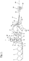
- the Figure 1 shows a schematic side view of a so-called hose machine for producing hose sections which are used as semi-finished products for the production of sacks.
- this hose machine consists of three processing points, not shown, in which web rolls 1, 2, 3 arranged one behind the other are held, from which flat webs of material 4, 5, 6 are withdrawn via guide rollers and unwinding and / or take-off devices.
- the webs 4 and 6 are made of paper and the web 5 is made of plastic.
- perforating cylinders 8, 9, 10, preferably provided with their own drives, are mounted in a perforating station 7, the perforating knives 11 of which interact with counter-knife cylinders 8 ', 9', 10 '.
- the perforating cylinders 8, 9, 10 can at the same time have embossing disks with which a longitudinal embossing can be introduced into one of the tracks.
- embossing disk 40 of the perforating station 8 is shown.
- Such an embossing disk can of course be provided in one or more perforating stations 8, 9, 10.
- transverse adhesive cylinders 12, 13 In the running direction of the mutually spaced webs, transverse adhesive cylinders 12, 13 provided with drives are mounted behind the transverse perforating cylinders 8 to 10 in the machine frame, the transverse adhesive strips of which provide the paper webs 5 and 6 with transverse adhesive applications.
- the transverse adhesive strips 14 of the transverse adhesive cylinders 12, 13 receive their adhesive applications in the usual manner from adhesive application rollers.
- only two cross glue cylinders are necessary.
- transverse gluing is carried out so that the individual layers do not move against one another when the areas of the tube pieces are folded during the manufacture of sacks.
- longitudinal adhesive strips 41 are also conceivable, of which only the longitudinal adhesive strip of the transverse adhesive cylinder 12 is shown.
- the transverse adhesive cylinder 13 can also be equipped with such a bar.
- the transverse adhesive cylinders can also be replaced by a plurality of glue nozzles arranged in the transverse direction, some of which can be controlled intermittently and thus assume the function of the transverse adhesive strips.
- Another part can be open continuously or almost continuously and can thus take over the function of the longitudinal adhesive strips.
- the area of the perforations in particular should preferably be excluded from the longitudinal gluing in order to prevent glue from later swelling out at the ends of the tube piece.
- the paper webs 4, 5, 6 are brought together to form a multi-layer web 15 for gluing them.
- This glue application device 30 can comprise several glue application valves 31, which release the glue flow onto the material webs or can interrupt this glue flow.
- the glue application valves receive the glue via various supply lines, of which the glue hose 32 is shown, which is fed with glue from a glue reservoir via a pump. Further feed lines are provided, but not shown in detail.
- the glue application valves 31 are distributed on one or more nozzle plates 33, in which non-visible glue channels which open into glue outlet openings are incorporated.
- the nozzle plate 33 is arranged on a support body 34, which in turn is connected in a suitable manner to the machine frame (not shown).
- the support body 34 can be arranged on a rod 35 about which it can be pivoted.
- the pivoted position is shown by a broken line. In this pivoted position, the so-called rinsing position, the glue application valves 31, the glue channels and other glue line components can be rinsed with a suitable cleaning agent, often water. The cleaning agent can be collected and drained off with the tub 36.
- the support body can be pivoted even further into a service position (not shown) so that components of the glue application device 30 are more accessible. It may be desirable, for example, to replace the nozzle plates 33 with others in which the distance between the glue outlet openings is changed transversely to the transport direction of the material web.
- one or more longitudinal adhesive rolls designed as glue application disks can also be provided, with which the later longitudinal seams can be provided with adhesive applications.
- a longitudinal adhesive roll is assigned to each layer.
- the longitudinal adhesive rollers receive their adhesive applications in the usual way from an adhesive application roller or scoop roller (not shown).
- a counter roller is provided on which the multilayer web is supported when it is provided with the longitudinal adhesive.
- the multi-layer web prepared in the manner described is then folded in a hose forming device 18 to form a hose 22, the respective non-overlapping edge regions of the individual layers sticking to one another.
- the tear-off station 19 In the tear-off station 19, individual tube sections 20 are then torn off the tube from the paper tube.
- the tear-off station is provided with a conventional tear-off mechanism, which comprises two rollers driven at different peripheral speeds, of which the front forms a holding roller and the rear forms a tear-off roller, with the individual sections 20 being torn off by a roller 21 provided with cams in a movable one Supported counter rollers are pressed against the holding and tear-off rollers.
- the Figure 2 shows a perspective view of a first hose section 20 according to the invention, which can be produced with a method according to the invention and with a device according to the invention.
- This hose piece comprises a rear wall 50 and a front wall 51, through a first Folding edge 52 and a second folding edge 53 are connected.
- the front wall can include the overlap area 54, in which the side areas of the previous flat webs 4, 5, 6 overlap and are connected to one another by the longitudinal adhesive.
- the tube piece 20 comprises an area, shown as line 55, with an increased rigidity of the tube piece. This area can comprise a solidified liquid and / or a strip of material and / or a deformation (mechanical deformation).
- the Figure 3 shows a further embodiment of a hose piece 20 according to the invention, in which a material strip 56 protrudes beyond the folded edge 53 and was thus also folded over when the hose was formed.
- the strip of material therefore has its own folded edge 57.
- List of reference symbols 1 Flat web roll 2 Flat web roll 3 Flat web roll 4th Flat track 5 Flat track 6th Flat track 7th Perforating station 8th Perforating cylinder 9 Perforating cylinder 10 Perforating cylinder 8th' Counter knife cylinder 9 ' Counter knife cylinder 10 ' Counter knife cylinder 11 Perforating knife 12th Cross gluing cylinder 13th Cross gluing cylinder 14th Transverse adhesive strips 15th multilayer web 16 17th 18th Hose forming device 19th Tear-off station 20th Individual hose sections 21 Camed roller 22nd hose 23 24 25th 26th 27 28 29 30th Glue application device 31 Glue application valve 32 Glue hose 33 Nozzle plate 34 Support body 35 pole 36 Tub 37 38 39 40 Embossing disk 41 Longitud
Landscapes
- Making Paper Articles (AREA)
Applications Claiming Priority (1)
| Application Number | Priority Date | Filing Date | Title |
|---|---|---|---|
| DE102020200408.0A DE102020200408A1 (de) | 2020-01-14 | 2020-01-14 | Verfahren und Vorrichtung zur Herstellung einzelner Schlauchstücke sowie Schlauchstücke und Säcke |
Publications (1)
| Publication Number | Publication Date |
|---|---|
| EP3851271A1 true EP3851271A1 (fr) | 2021-07-21 |
Family
ID=74180933
Family Applications (1)
| Application Number | Title | Priority Date | Filing Date |
|---|---|---|---|
| EP21020009.3A Pending EP3851271A1 (fr) | 2020-01-14 | 2021-01-12 | Procédé et dispositif de fabrication de pièces tubulaires individuelles, ainsi que pièces tubulaires et sacs |
Country Status (2)
| Country | Link |
|---|---|
| EP (1) | EP3851271A1 (fr) |
| DE (1) | DE102020200408A1 (fr) |
Cited By (1)
| Publication number | Priority date | Publication date | Assignee | Title |
|---|---|---|---|---|
| CN117901207A (zh) * | 2023-12-20 | 2024-04-19 | 惠州恒铭达电子科技有限公司 | 一种纸卡全自动折弯冲切加工工艺 |
Families Citing this family (1)
| Publication number | Priority date | Publication date | Assignee | Title |
|---|---|---|---|---|
| CN116512672B (zh) * | 2023-03-17 | 2025-08-19 | 佛山市达肯包装机械有限公司 | 零折位夹纸装置 |
Citations (5)
| Publication number | Priority date | Publication date | Assignee | Title |
|---|---|---|---|---|
| GB248037A (en) * | 1924-11-20 | 1926-02-22 | Harold Gotch Robinson | Improvements in and relating to paper bags, and bag-making tubes, and to the manufacture thereof |
| US2114625A (en) * | 1937-05-01 | 1938-04-19 | Edna May Bergstein | Method of forming containers |
| EP1106508A1 (fr) * | 1999-12-01 | 2001-06-13 | Rovema Verpackungsmaschinen GmbH | Macine pour fabriquer des sacs tubulaires |
| US20110002561A1 (en) * | 2010-06-24 | 2011-01-06 | Vir Narula | Reinforced bag |
| EP2392452A2 (fr) * | 2010-06-02 | 2011-12-07 | Windmöller & Hölscher KG | Dispositif et procédé de production de tuyaux ou de sections de tuyaux |
-
2020
- 2020-01-14 DE DE102020200408.0A patent/DE102020200408A1/de active Pending
-
2021
- 2021-01-12 EP EP21020009.3A patent/EP3851271A1/fr active Pending
Patent Citations (5)
| Publication number | Priority date | Publication date | Assignee | Title |
|---|---|---|---|---|
| GB248037A (en) * | 1924-11-20 | 1926-02-22 | Harold Gotch Robinson | Improvements in and relating to paper bags, and bag-making tubes, and to the manufacture thereof |
| US2114625A (en) * | 1937-05-01 | 1938-04-19 | Edna May Bergstein | Method of forming containers |
| EP1106508A1 (fr) * | 1999-12-01 | 2001-06-13 | Rovema Verpackungsmaschinen GmbH | Macine pour fabriquer des sacs tubulaires |
| EP2392452A2 (fr) * | 2010-06-02 | 2011-12-07 | Windmöller & Hölscher KG | Dispositif et procédé de production de tuyaux ou de sections de tuyaux |
| US20110002561A1 (en) * | 2010-06-24 | 2011-01-06 | Vir Narula | Reinforced bag |
Cited By (1)
| Publication number | Priority date | Publication date | Assignee | Title |
|---|---|---|---|---|
| CN117901207A (zh) * | 2023-12-20 | 2024-04-19 | 惠州恒铭达电子科技有限公司 | 一种纸卡全自动折弯冲切加工工艺 |
Also Published As
| Publication number | Publication date |
|---|---|
| DE102020200408A1 (de) | 2021-07-15 |
Similar Documents
| Publication | Publication Date | Title |
|---|---|---|
| EP2276628B1 (fr) | Dispositif et procédé pour produire des sacs | |
| EP1437202B1 (fr) | Dispositif et procédé pour la séparation de poses dans une machine pour la production d'éléments plans découpés à partir d'une bande | |
| EP2464510B1 (fr) | Procédé de production d'un sac ou sachet à l'aide d'une voile de matière plastique | |
| EP3603948B1 (fr) | Installation de fabrication de carton ondulé | |
| EP2049327A1 (fr) | Procédé de fabrication de sachets d'emballage avec une zone de fond renforcée ainsi que dispositif de réalisation du procédé | |
| EP2608954A2 (fr) | Sac, procédé et dispositif de fabrication de sacs | |
| EP2276613B1 (fr) | Cylindre à aiguilles | |
| EP0744365A2 (fr) | Méthode pour changer le rouleau dans une machine à enrouler et machine à enrouler pour l'application de cette méthode | |
| DE102009000893B4 (de) | Verfahren und Vorrichtung zum Transport von flachen Werkstücken | |
| DE102020200408A1 (de) | Verfahren und Vorrichtung zur Herstellung einzelner Schlauchstücke sowie Schlauchstücke und Säcke | |
| EP2392452B1 (fr) | Dispositif et procédé de production de tuyaux ou de sections de tuyaux | |
| DE9217023U1 (de) | Verpackungsbeutel aus Papier oder Kunststoff | |
| EP1842814A2 (fr) | Dispositif pour remplacer une première bande de matériau par une deuxième bande de matériau | |
| EP1976789A1 (fr) | Dispositif de freinage de feuilles, notamment de feuilles de papier ou de carton destinées à être déposées sur une pile | |
| WO2016005284A1 (fr) | Procédé de fabrication de sacs ou de poches ainsi que sacs ou poches | |
| EP3059092B1 (fr) | Dispositif de fabrication de produits imprimes relies par encollage | |
| DE2642708A1 (de) | Verfahren und vorrichtung zum herstellen von insbesondere zigarettenpackungen | |
| DE2218992C3 (de) | Verfahren und Vorrichtung zum wahlweisen Herstellen von Briefhüllen aus Vorratsrollen und vom Blatt bzw. vom Stapel | |
| EP1429698B1 (fr) | Groupement de materiaux sous forme de pellicules ou de feuilles | |
| DE102011003380B4 (de) | Verfahren und ein System zum Abarbeiten zumindest zweier aufeinander folgender Aufträge zur Herstellung von Säcken | |
| DE3614917A1 (de) | Verfahren und vorrichtung zum verpacken von produkten | |
| CH694528A5 (de) | Vorrichtung zum Aufbringen eines Klebers auf eine Materialbahn. | |
| DE102021115984A1 (de) | Vorrichtung und Verfahren der Tabak verarbeitenden Industrie zum Verbinden zweier Materialbahnen | |
| DE102013201901B4 (de) | Verfahren und Vorrichtung zur Herstellung eines mehrlagigen Druckproduktes sowie Druckmaschine | |
| DE2752123A1 (de) | Verfahren zum herstellen von drucksachentaschen |
Legal Events
| Date | Code | Title | Description |
|---|---|---|---|
| PUAI | Public reference made under article 153(3) epc to a published international application that has entered the european phase |
Free format text: ORIGINAL CODE: 0009012 |
|
| STAA | Information on the status of an ep patent application or granted ep patent |
Free format text: STATUS: THE APPLICATION HAS BEEN PUBLISHED |
|
| AK | Designated contracting states |
Kind code of ref document: A1 Designated state(s): AL AT BE BG CH CY CZ DE DK EE ES FI FR GB GR HR HU IE IS IT LI LT LU LV MC MK MT NL NO PL PT RO RS SE SI SK SM TR |
|
| STAA | Information on the status of an ep patent application or granted ep patent |
Free format text: STATUS: REQUEST FOR EXAMINATION WAS MADE |
|
| 17P | Request for examination filed |
Effective date: 20220121 |
|
| RBV | Designated contracting states (corrected) |
Designated state(s): AL AT BE BG CH CY CZ DE DK EE ES FI FR GB GR HR HU IE IS IT LI LT LU LV MC MK MT NL NO PL PT RO RS SE SI SK SM TR |