EP3851621A2 - Système de porte coulissante - Google Patents
Système de porte coulissante Download PDFInfo
- Publication number
- EP3851621A2 EP3851621A2 EP20209433.0A EP20209433A EP3851621A2 EP 3851621 A2 EP3851621 A2 EP 3851621A2 EP 20209433 A EP20209433 A EP 20209433A EP 3851621 A2 EP3851621 A2 EP 3851621A2
- Authority
- EP
- European Patent Office
- Prior art keywords
- fastening
- bolt
- sliding door
- door leaf
- running rail
- Prior art date
- Legal status (The legal status is an assumption and is not a legal conclusion. Google has not performed a legal analysis and makes no representation as to the accuracy of the status listed.)
- Granted
Links
Images


Classifications
-
- E—FIXED CONSTRUCTIONS
- E05—LOCKS; KEYS; WINDOW OR DOOR FITTINGS; SAFES
- E05D—HINGES OR SUSPENSION DEVICES FOR DOORS, WINDOWS OR WINGS
- E05D5/00—Construction of single parts, e.g. the parts for attachment
- E05D5/02—Parts for attachment, e.g. flaps
- E05D5/0246—Parts for attachment, e.g. flaps for attachment to glass panels
-
- E—FIXED CONSTRUCTIONS
- E05—LOCKS; KEYS; WINDOW OR DOOR FITTINGS; SAFES
- E05D—HINGES OR SUSPENSION DEVICES FOR DOORS, WINDOWS OR WINGS
- E05D15/00—Suspension arrangements for wings
- E05D15/06—Suspension arrangements for wings for wings sliding horizontally more or less in their own plane
- E05D15/0621—Details, e.g. suspension or supporting guides
- E05D15/0626—Details, e.g. suspension or supporting guides for wings suspended at the top
- E05D15/063—Details, e.g. suspension or supporting guides for wings suspended at the top on wheels with fixed axis
- E05D15/0634—Details, e.g. suspension or supporting guides for wings suspended at the top on wheels with fixed axis with height adjustment
-
- E—FIXED CONSTRUCTIONS
- E05—LOCKS; KEYS; WINDOW OR DOOR FITTINGS; SAFES
- E05F—DEVICES FOR MOVING WINGS INTO OPEN OR CLOSED POSITION; CHECKS FOR WINGS; WING FITTINGS NOT OTHERWISE PROVIDED FOR, CONCERNED WITH THE FUNCTIONING OF THE WING
- E05F1/00—Closers or openers for wings, not otherwise provided for in this subclass
- E05F1/08—Closers or openers for wings, not otherwise provided for in this subclass spring-actuated, e.g. for horizontally sliding wings
- E05F1/16—Closers or openers for wings, not otherwise provided for in this subclass spring-actuated, e.g. for horizontally sliding wings for sliding wings
-
- E—FIXED CONSTRUCTIONS
- E05—LOCKS; KEYS; WINDOW OR DOOR FITTINGS; SAFES
- E05F—DEVICES FOR MOVING WINGS INTO OPEN OR CLOSED POSITION; CHECKS FOR WINGS; WING FITTINGS NOT OTHERWISE PROVIDED FOR, CONCERNED WITH THE FUNCTIONING OF THE WING
- E05F5/00—Braking devices, e.g. checks; Stops; Buffers
- E05F5/003—Braking devices, e.g. checks; Stops; Buffers for sliding wings
-
- E—FIXED CONSTRUCTIONS
- E05—LOCKS; KEYS; WINDOW OR DOOR FITTINGS; SAFES
- E05Y—INDEXING SCHEME ASSOCIATED WITH SUBCLASSES E05D AND E05F, RELATING TO CONSTRUCTION ELEMENTS, ELECTRIC CONTROL, POWER SUPPLY, POWER SIGNAL OR TRANSMISSION, USER INTERFACES, MOUNTING OR COUPLING, DETAILS, ACCESSORIES, AUXILIARY OPERATIONS NOT OTHERWISE PROVIDED FOR, APPLICATION THEREOF
- E05Y2201/00—Constructional elements; Accessories therefor
- E05Y2201/20—Brakes; Disengaging means; Holders; Stops; Valves; Accessories therefor
- E05Y2201/218—Holders
- E05Y2201/22—Locks
-
- E—FIXED CONSTRUCTIONS
- E05—LOCKS; KEYS; WINDOW OR DOOR FITTINGS; SAFES
- E05Y—INDEXING SCHEME ASSOCIATED WITH SUBCLASSES E05D AND E05F, RELATING TO CONSTRUCTION ELEMENTS, ELECTRIC CONTROL, POWER SUPPLY, POWER SIGNAL OR TRANSMISSION, USER INTERFACES, MOUNTING OR COUPLING, DETAILS, ACCESSORIES, AUXILIARY OPERATIONS NOT OTHERWISE PROVIDED FOR, APPLICATION THEREOF
- E05Y2201/00—Constructional elements; Accessories therefor
- E05Y2201/40—Motors; Magnets; Springs; Weights; Accessories therefor
- E05Y2201/404—Function thereof
- E05Y2201/41—Function thereof for closing
- E05Y2201/412—Function thereof for closing for the final closing movement
-
- E—FIXED CONSTRUCTIONS
- E05—LOCKS; KEYS; WINDOW OR DOOR FITTINGS; SAFES
- E05Y—INDEXING SCHEME ASSOCIATED WITH SUBCLASSES E05D AND E05F, RELATING TO CONSTRUCTION ELEMENTS, ELECTRIC CONTROL, POWER SUPPLY, POWER SIGNAL OR TRANSMISSION, USER INTERFACES, MOUNTING OR COUPLING, DETAILS, ACCESSORIES, AUXILIARY OPERATIONS NOT OTHERWISE PROVIDED FOR, APPLICATION THEREOF
- E05Y2201/00—Constructional elements; Accessories therefor
- E05Y2201/40—Motors; Magnets; Springs; Weights; Accessories therefor
- E05Y2201/46—Magnets
- E05Y2201/462—Electromagnets
-
- E—FIXED CONSTRUCTIONS
- E05—LOCKS; KEYS; WINDOW OR DOOR FITTINGS; SAFES
- E05Y—INDEXING SCHEME ASSOCIATED WITH SUBCLASSES E05D AND E05F, RELATING TO CONSTRUCTION ELEMENTS, ELECTRIC CONTROL, POWER SUPPLY, POWER SIGNAL OR TRANSMISSION, USER INTERFACES, MOUNTING OR COUPLING, DETAILS, ACCESSORIES, AUXILIARY OPERATIONS NOT OTHERWISE PROVIDED FOR, APPLICATION THEREOF
- E05Y2201/00—Constructional elements; Accessories therefor
- E05Y2201/60—Suspension or transmission members; Accessories therefor
- E05Y2201/622—Suspension or transmission members elements
- E05Y2201/64—Carriers
-
- E—FIXED CONSTRUCTIONS
- E05—LOCKS; KEYS; WINDOW OR DOOR FITTINGS; SAFES
- E05Y—INDEXING SCHEME ASSOCIATED WITH SUBCLASSES E05D AND E05F, RELATING TO CONSTRUCTION ELEMENTS, ELECTRIC CONTROL, POWER SUPPLY, POWER SIGNAL OR TRANSMISSION, USER INTERFACES, MOUNTING OR COUPLING, DETAILS, ACCESSORIES, AUXILIARY OPERATIONS NOT OTHERWISE PROVIDED FOR, APPLICATION THEREOF
- E05Y2600/00—Mounting or coupling arrangements for elements provided for in this subclass
- E05Y2600/50—Mounting methods; Positioning
- E05Y2600/502—Clamping
-
- E—FIXED CONSTRUCTIONS
- E05—LOCKS; KEYS; WINDOW OR DOOR FITTINGS; SAFES
- E05Y—INDEXING SCHEME ASSOCIATED WITH SUBCLASSES E05D AND E05F, RELATING TO CONSTRUCTION ELEMENTS, ELECTRIC CONTROL, POWER SUPPLY, POWER SIGNAL OR TRANSMISSION, USER INTERFACES, MOUNTING OR COUPLING, DETAILS, ACCESSORIES, AUXILIARY OPERATIONS NOT OTHERWISE PROVIDED FOR, APPLICATION THEREOF
- E05Y2800/00—Details, accessories and auxiliary operations not otherwise provided for
- E05Y2800/67—Materials; Strength alteration thereof
- E05Y2800/672—Glass
-
- E—FIXED CONSTRUCTIONS
- E05—LOCKS; KEYS; WINDOW OR DOOR FITTINGS; SAFES
- E05Y—INDEXING SCHEME ASSOCIATED WITH SUBCLASSES E05D AND E05F, RELATING TO CONSTRUCTION ELEMENTS, ELECTRIC CONTROL, POWER SUPPLY, POWER SIGNAL OR TRANSMISSION, USER INTERFACES, MOUNTING OR COUPLING, DETAILS, ACCESSORIES, AUXILIARY OPERATIONS NOT OTHERWISE PROVIDED FOR, APPLICATION THEREOF
- E05Y2900/00—Application of doors, windows, wings or fittings thereof
- E05Y2900/10—Application of doors, windows, wings or fittings thereof for buildings or parts thereof
- E05Y2900/13—Type of wing
- E05Y2900/132—Doors
Definitions
- the present invention relates to a sliding door system with a running rail extending in a longitudinal direction and a door leaf guided thereon with at least one carriage, the carriage having a carriage guided in the running rail and a fastening device connected to the carriage, via which the carriage on an upper edge of the door leaf is attached.
- Such sliding door systems are generally known.
- the door leaf is carried by the running rail via the drive so that the weight of the door leaf is transferred to the running rail via the carriage.
- the carriage rolls with one or more rollers in a track of the running rail.
- sliding door systems in which the running rail has a track for the running gear, the carriage of the running gear having one or more running rollers on one side, which are guided in the running track.
- the door leaf with the mounted running gear is usually hooked into the running rail from the longitudinal side of the running rail during assembly.
- Such a sliding door system is, for example, off DE 10 2011 012 286 A1 known to the applicant.
- the sliding door system according to the invention is defined by the features of claim 1.
- the at least one running gear has a carriage guided in the running rail by means of at least one roller and one with the carriage connected fastening device, wherein the at least one drive is fastened to an upper edge of the door leaf, wherein the fastening device has an upwardly projecting fastening portion.
- the invention is characterized in that the fastening device in the fastening section has a recess, which has an opening directed in the longitudinal direction of the running rail, for receiving a fastening part of the carriage, the recess extending in the longitudinal direction of the running rail and in the vertical direction, and one in the Recess protruding projection is formed and the recess forms a limited by the projection and a portion of the fastening portion opposite the projection seat for the fastening part, wherein the fastening part of the carriage is insertable through the opening into the recess and movable into the seat and wherein the fastening part of the The carriage can be fastened to the fastening device via at least one fastening means in the position resting on the seat.
- the sliding door system according to the invention makes it possible, in a simple manner, that the carriage is initially inserted into a compactly designed running rail can be used and then moved in the longitudinal direction of the running rail to be connected to the fastening device of the door leaf.
- the fastening part of the carriage Through the opening of the recess directed in the longitudinal direction of the running rail, the fastening part of the carriage can be easily inserted into the recess and moved into the seat when the carriage is moved in the running rail.
- the weight of the door leaf can advantageously be transmitted via the fastening device to the carriage and thus to the running rail.
- the projection and the section lying opposite the projection can be connected to form the seat, wherein, for example, the seat can have an arcuate shape.
- the shape of the seat is adapted to the shape of the fastening part.
- the projection and the section of the fastening section opposite the projection can prevent a relative movement of the carriage and the fastening device in a form-fitting manner in that the projection and the section opposite the projection bear against the fastening part.
- the recess can basically have a shape that corresponds to an L-shape.
- the arrangement according to the invention also enables the fastening means to provide only a small force for fastening the carriage to the fastening device, since the recess and the seat formed therein a form-fitting connection is formed between the carriage and the fastening device, the weight force being transmitted from the fastening device to the carriage via a form-fit connection.
- the carriage is guided in the running rail in that at least one roller can roll on at least one running track of the running rail. It is preferably provided that the carriage only has one or more rollers on one side, which are guided in a track of the running rail. In this way, a particularly compact design of the running rail and running gear is possible.
- the running rail can have a rail projection which extends in the longitudinal direction of the running rail and which forms a securing device for the carriage.
- the rail projection is arranged, for example, in the vertical direction above the track. The distance in the vertical direction between the rail projection and the track can be selected so that the roller can be swiveled in under the rail projection when the carriage is inserted without a door leaf.
- the rail projection can also be arranged so close to the track that when the carriage is in the inserted state, there is only a distance of a few millimeters or even less than one millimeter from the roller, so that the carriage cannot be swiveled in. In this case, the carriage is to be introduced from a longitudinal end of the running rail.
- the door leaf is understood to mean the plate-shaped part of the sliding door / the door leaf.
- the drive is an add-on part on the door leaf and is therefore not to be understood as part of the door leaf.
- the sliding door system according to the invention is particularly suitable for glass doors in which the door leaf consists of glass or largely of glass.
- the fastening part is designed as a cylindrical axis extending in the horizontal direction transversely to the longitudinal direction of the running rail, the at least one roller being connected to the cylindrical axis directly or via a roller block.
- the order in the horizontal direction transversely to the longitudinal direction of the running rail is present in the suspended state of the door leaf.
- the formation of the fastening part as a cylindrical axis enables a structurally simple design of the fastening part, with the fastening part being insertable into the recess in a simple manner. Furthermore, when the fastening part is arranged in the seat, it can advantageously be fastened independently of its rotational orientation.
- a roller axis can be arranged eccentrically to a central axis of the cylindrical axis. This makes it possible for the position of the roller to be adjusted in the vertical direction (when the door leaf is suspended in the running rail) by rotating the fastening part about the central axis of the cylindrical axis, so that a height adjustment device is formed. In other words: for height adjustment it is only necessary to rotate the fastening part and to fix it in a desired position by means of the at least one fastening means.
- the cylindrical axis can be rotated in a released state in the seat, the axis being able to be fastened in a rotational position in the seat via the at least one fastening means.
- the at least one fastening means can be a screw nut which can be screwed onto a thread of the cylindrical shaft. A frictional force with a surface of the fastening section, which fixes the fastening part, can be produced via the screw nut. In this way, the fastening of the fastening part is possible in a simple manner.
- the opening of the recess can be arranged facing in the longitudinal direction of the running rail on the first side edge of the door leaf.
- the recess is arranged in a central section of the fastening section, with a bolt receptacle for receiving a bolt of a bolt device fastened at least indirectly on or in the running rail being formed on the opening in the direction facing away from the recess.
- the drive according to the invention can advantageously be combined with a locking device for locking the sliding door system, with a compact design of the drive and the sliding door system being maintained.
- the latch receptacle has a receiving plate which is arranged laterally on the fastening section and extends parallel to the fastening section.
- the receiving plate can advantageously be fastened to the fastening device, for example also after the door leaf has been hung in, it being possible to maintain a compact design of the drive.
- the receiving plate has a latch retainer.
- the bolt retainer In the locked state of the locking device, the bolt retainer can hold back the bolt received in the bolt recess so that the door leaf is locked.
- the lock device formed by the locking device which can advantageously lock the door leaf in a closed position, preferably has the following configuration.
- the bolt receptacle can furthermore have a bolt actuator which is spaced apart from the bolt actuator.
- the bolt can be inserted between the bolt actuator and the bolt retainer when the door is closed, the bolt actuator guiding the bolt into a retaining position when the door is closed against an automatic return force.
- the bolt engages behind the bolt retainer, the bolt device having a bolt holding device which holds the bolt in the retaining position when the lock device is in the locked state.
- the bolt actuator guides the bolt into the restraint position when the door leaf is closed, no separate drive is required for the bolt, which reduces the complexity of the bolt device.
- the bolt is driven by the closing movement of the door. For example, the latch operator can push the latch into the restraint position.
- the bolt holding device can also be designed in such a way that the bolt holding device can be activated before the door leaf is closed and the bolt is then lifted from the basic position into the retaining position by the bolt operator despite the holding force of the bolt holding device and then by the bolt holding device can be held in the restraint position.
- the bolt can thus engage in the bolt receptacle in the closed state of the door leaf and in the locked state of the lock device the bolt receptacle holds the bolt back. It can be provided that in the restraint position the bolt is arranged between the bolt actuator and bolt retainer.
- the automatic return force can, for example, take place via gravity.
- a spring device is arranged on the bolt, which pulls the bolt in the direction of the basic position.
- the bolt operator guides the bolt from the restraint position into the basic position when the door leaf is opened in the unlocked state of the lock apparatus, with the automatic return force pressing the bolt against the bolt operator.
- the bolt can be guided in an advantageous manner when the door leaf is opened, since the bolt always rests against the bolt actuator due to the return force.
- the bolt holding device can be operated electrically, whereby when the bolt holding device is switched off, it releases the bolt, so that the bolt is then guided into the basic position due to the independent return force when the door leaf is opened can.
- the door leaf of the sliding door system according to the invention can therefore always be opened.
- the bolt has a pivot bearing and the bolt actuator guides the bolt in a pivoting movement.
- the bolt can be guided in a particularly advantageous manner into the retention position in which the bolt engages behind the bolt retainer.
- the pivot bearing can, for example, have an axis of rotation arranged in the horizontal direction transversely to the longitudinal direction of the running rail.
- the bolt can be pivoted in a vertical plane extending in the longitudinal direction of the running rail.
- the bolt actuator and the bolt retainer are arranged spaced apart in the vertical direction, preferably arranged one above the other.
- the bolt holding device is designed as a controllable magnet and the bolt consists at least partially of a ferromagnetic material.
- the lock device can advantageously be operated electrically by using an electromagnet.
- the magnet pulls the bolt when actuated until the bolt rests against the magnet.
- the bolt can be held in the retaining position in a particularly advantageous manner by means of the bolt holding device. The fact that the bolt rests against the magnet creates a frictional force between the magnet and bolt, whereby the bolt can advantageously be held in the retaining position.
- the magnet attracts the bolt in a direction transverse to the plane in which the bolt can be moved from the basic position into the retention position.
- the magnet thus attracts the bolt transversely to the pivoting plane.
- the magnet thus acts transversely to the direction in which the automatic return force acts.
- the frictional force generated between the magnet and the bolt thus counteracts the automatic return force.
- the bolt holding device in which the bolt holding device is designed as a controllable magnet, the bolt holding device can advantageously be activated before the door leaf is closed and the bolt can be lifted from the basic position into the retaining position by the bolt actuator despite the holding force of the bolt holding device .
- the locking device is attached to a limiting device for limiting the path of travel of the door leaf.
- the locking device can thus form a structural unit with the limiting device. This simplifies the assembly of the sliding door system according to the invention, since only the combination of limiting device and locking device has to be fastened in the running rail. In addition, installation errors are avoided, since it is ensured that the bolt is in the correct position in relation to the end position of the door leaf predetermined by the limiting device.
- the bolt actuator and the bolt retainer are designed as projections which preferably extend in the horizontal direction transversely to the longitudinal direction of the running rail. In this way, the bolt actuator and the bolt retainer can be provided in a structurally simple manner.
- the bolt actuator and the bolt retainer are designed symmetrically to a central plane of the bolt retainer extending in the longitudinal direction of the bolt retainer.
- the receiving plate of the bolt receptacle can advantageously be used on a drive arranged on the left or right-hand side by correspondingly turning the receiving plate.
- the fastening device is designed as a clamping device, a main body of the limiting device forming clamping jaws on both sides of the door leaf, a clamping plate being arranged on one clamping jaw, which can be displaced in the direction of the door leaf.
- a fastening device of this type can be fastened in a particularly advantageous manner to a door leaf, in particular to a door leaf made of glass, even with different material thicknesses of the glass.
- the main body is an extruded profile, preferably an extruded aluminum profile. In this way, the main body and thus the fastening device can be produced in a simple manner.
- the clamping plate can be made of sheet metal, for example, and can be moved in the direction of the door leaf by means of screws to provide the clamping force.
- the recess can be produced by means of a milling process.
- the clamping jaws each have a thickening. In this way, greater stability of the clamping jaw is made possible, in particular in the transition area to the remaining part of the main body.
- the fastening section adjoins one of the clamping jaws in the vertical direction.
- the vertical direction refers to the hinged state of the door leaf.
- a damper unit with a pull-in function arranged in the running rail is provided and a coupler is arranged on the drive which engages with an engaging part of the damper unit in a latching manner, the damper unit initially moving the door leaf towards an end position brakes and then drives into the end position, and wherein the coupler is adjustable in the vertical direction.
- the vertical direction refers to the hooked one State of the door leaf.
- the damper unit with pull-in function By means of the damper unit with pull-in function, it can advantageously be made possible that the door leaf can initially be moved freely when it is moved into the end position, then is braked by the damper unit with pull-in function, the coupler engaging with an engaging part and finally by the damper unit with pull-in function is gently driven into its end position.
- the coupler in the vertical direction By adjusting the coupler in the vertical direction, the system formed from the damper unit and coupler can advantageously be adapted to the door leaf adjusted by means of the height adjustment.
- the damper unit is attached or fixed to the delimitation device for delimiting the path of travel of the door leaf.
- the damper unit and the limiting device can form a structural unit so that assembly is simplified and installation errors are avoided.
- the damper unit can be fixed on the limiting device, for example, by means of a dowel pin.
- the structural unit can consist of a damper unit, a limiting device and a locking device.
- the coupler can have a fastening section with an elongated hole which extends in the vertical direction and through which a screw engages.
- the vertical direction refers to the hinged state of the door leaf. In this way, an adjustment of the coupler in the vertical direction is possible in a simple manner.
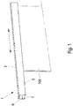
- FIG. 1 a sliding door system 1 according to the invention is shown schematically in a perspective illustration.
- the sliding door system 1 has a running rail 3 extending in the longitudinal direction, in which a door leaf with an in Figure 1 Not drive 4 shown is performed.
- the longitudinal direction is indicated by a double arrow.
- the running rail 3 has an essentially C-shaped cross section, the interior of the running rail 3 being concealed from the viewer via a panel 5.
- the running rail 3 forms a running track 7 for the running gear 4.
- a rail projection 6 which extends in the longitudinal direction of the running rail 3 and forms a securing device for the door leaf 100.
- the drive 4 consists of a carriage 9 which is fastened to a fastening device 11.
- the drive 4 is fastened to an upper edge 100a of the door leaf 100 via the fastening device 11.
- the fastening device has an upwardly projecting fastening section 12.
- the fastening section 12 has a recess 13 which has an opening 15 directed in the longitudinal direction of the running rail.
- the recess 13 has an approximately L-shaped course, so that in the in Figure 2b shown upright position of the door leaf 100, which corresponds to the position of the door leaf 100 in the suspended state, the recess 13 initially runs essentially in the longitudinal direction of the running rail 3 and then vertically upwards.
- the fastening part 23 of the carriage 9 which can be designed as a cylindrical axis, for example, can be inserted through the opening 15 into the recess 13 and pushed into the seat 21 so that the seat 21 rests against the fastening part 23.
- the carriage 9 can be fastened to the fastening section 12 by means of a fastening means 25 in the form of a nut. In the suspended state of the door leaf 100, the weight of the door leaf 100 is positively transmitted via the seat 21 to the carriage 9.
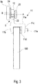
- FIG. 3 shows, in which a schematic view of the door leaf 100 is shown in the longitudinal direction of the running rail 3, the fastening device 11 is designed as a clamping device, with a main body 11a on both sides of the door leaf 100 forming jaws 11b, 11c.
- the clamping jaws 11b, 11c each have a thickening.
- a clamping plate 11d is arranged on one of the clamping jaws 11c on the side facing the door leaf 100, the clamping plate 11d being displaceable in the direction of the door leaf 100 by means of screws 11e to apply the clamping force.
- the carriage 9 has a roller 9a which is fastened to a roller block 24.
- the roller block 24 is connected to the fastening part 23, an eccentric arrangement of the roller 9a being formed, the roller axis B being arranged eccentrically to the central axis A of the fastening part 23.
- the fastening part 23 can be rotated in the seat 21, so that the position of the roller 9a can be changed in the vertical direction and thus a height adjustment of the door leaf 100 is made possible.
- the carriage 9 can be fastened again to the fastening device 11 by means of the fastening means 25.
- the opening 15 is arranged in the longitudinal direction of the running rail 3 facing a first side edge 100b of the door leaf, whereby the carriage 9 can advantageously be inserted into the opening 15 after being inserted into the running rail 3 and fastened to the fastening device 11.
- the fastening section 12 extends in the vertical direction adjoining the clamping jaw 11b.
- the main body 11a of the fastening device 11, the jaws 11b, 11c and the Has fastening portion 12, can be formed from an extruded profile, wherein the recess 13 can be milled out.
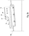
- FIG. 4 a second embodiment of the sliding door system according to the invention is shown schematically in a perspective view.
- the running rail 3 is in Fig. 4 shown without the aperture 5.
- the drive 4 arranged on the upper edge of the door leaf 100 has essentially the same structure as the drive described above.
- the sliding door system 1 differs from the previously described sliding door system in that a damper unit 27 with a pull-in function is arranged in the running rail 3 and interacts with a coupler 29 arranged on the carriage 4.
- the damper unit 27 has an engaging part 31 with which the coupler 29 engages in a latching manner.
- the door leaf 100 is first braked via the damper unit 27 and then driven into the end position in which it rests against the limiting device 33.
- the coupler 29 is designed to be adjustable in height.
- the coupler 29 has an adjustment section 29a which has an elongated hole extending in the vertical direction through which a screw 29b engages.
- the coupler 29 is fastened to the drive 4 via the screw. By loosening the screw, the adjustment section 29a and thus the coupler 29 can be adjusted in the vertical direction and fastened in the desired position via the screw 29b.
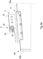
- FIG. 13 is a view of the embodiment of FIG Figure 4 shown in the longitudinal direction of the running rail 3 in the state inserted into the running rail 3.
- the running rail 3 can be made very compact, since the drive 4 is also very compact.
- the roller 9a is inserted into the track 7.
- the running rail 3 has a rail projection 6 which extends in the longitudinal direction of the running rail and which is located above the running track 7 and forms a safety device for the carriage 9 to be unhooked.
- the distance in the vertical direction between the rail projection 6 and the track 7 is selected so that the roller 9a can be pivoted into the track 3 when the carriage 9 is inserted.
- the carriage 9 is inserted in the detached state from the fastening device 11 and thus without the door leaf 100. After the carriage 9 has been inserted into the track 7, the carriage 9 can be moved in the longitudinal direction of the track 3 and after being inserted into the recess 13 the fastening device 11 are attached.
- the sliding door system 1 has a lock device 35.
- the lock device 35 has a bolt receptacle 37 which is arranged on the drive 4, as well as a bolt device 39 which is fastened in the running rail.
- the locking device 29 can, for example, form a structural unit together with a limiting device for limiting the travel path of the door leaf 100.
- the bolt receptacle has a receiving plate 37a which is fastened to the fastening section 12 of the fastening device 11.
- the bolt receptacle 37 is not shown for the sake of clarity.
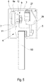
- a receiving space 37b for a bolt 41 of the locking device 39 is formed on the opening 15 of the recess 13 via the bolt receptacle 37 in the direction facing away from the recess 13.
- the locking device 39 has a locking bar 41 which extends essentially in the longitudinal direction of the running rail 3 and has a hook-shaped section 41a at its end.
- the bolt 41 is pivotably mounted in a vertical plane extending in the longitudinal direction of the running rail 3.
- the bolt 41 has a pivot bearing 43 which engages the end of the bolt 41 opposite the hook-shaped section 41a.
- the pivot bearing 43 forms an axis of rotation for the bolt 41 running in the horizontal direction transversely to the longitudinal direction of the running rail 3.
- the bolt 41 also has a guide device 45. The pivoting movement of the bolt 41 is guided via the guide device 45 and limited upwards and downwards.
- the bolt 41 engages in the bolt receptacle 37.
- the hook-shaped section 41a and a further part of the bolt are located in the receiving space 37b of the bolt receptacle 37.
- the bolt receptacle 37 has a bolt actuator 47 and a bolt retainer 49, which in vertical Direction are arranged spaced from each other.
- the bolt device 39 also has a bolt holding device 51 which holds the bolt 41 in a retaining position in the locked state of the door leaf 100. In this position, opening of the door leaf 100 is prevented in that the bolt 41 interacts with the bolt retainer 49 via its hook-shaped section 41a.
- the bolt 41 In a state in which the bolt 41 has not yet been inserted into the bolt receptacle 37 and the bolt holding device 51 is deactivated, the bolt 41 is in a basic position into which the bolt 41 is due to a by the Automatic feedback force formed by gravity is moved.
- the basic position is in Fig. 7 shown.
- the bolt 41 is first inserted with the hook-shaped section 41a into the opening formed between the bolt actuator 47 and the bolt retainer 49.
- the bolt actuator 47 pushes against the bolt device 39 and, as the door leaf 100 continues to move towards the end position, pushes the bolt 41 against the automatic return force and regardless of whether the bolt retaining device 51 is activated or deactivated, upwards into the restraint position.
- the bolt holding device 51 is designed as a controllable magnet.
- the bolt 41 is made of a ferromagnetic material. When the magnet is actuated, it pulls the bolt 41 in a horizontal direction transversely to the longitudinal direction of the running rail 3, so that the bolt 41 rests partially on the magnet. As a result, a frictional connection is formed between the magnet and the bolt 41, so that the bolt cannot return to the basic position due to the automatic return force.
- the locking device 51 can be activated before the door leaf 100 is closed.
- the bolt 41 is then raised by the bolt actuator 47 from the basic position into the retaining position despite the holding force of the bolt retaining device 51 and then held in the retaining position by the bolt retaining device 51.
- the activation of the bolt holding device 51 before the door leaf 100 is closed has the advantage that the locking process of the door leaf 100 can be initiated regardless of its position, whereby it is ensured that the door leaf 100 is locked in its closed position after the next procedure.
- the bolt actuator 47 and the bolt retainer 49 are designed as projections which extend in the horizontal direction transversely to the longitudinal direction of the running rail 3 extend.
- the bolt actuator 47 and the bolt retainer 49 are designed symmetrically with respect to a horizontally extending center plane of the bolt retainer 37 extending in the longitudinal direction of the bolt retainer 37 and thus in the longitudinal direction of the running rail 3.
- the lock device 19 of the sliding door system 1 has the advantage that only the bolt holding device 51 has to be actuated for the locking process of the lock device 19, which pulls the bolt 41 and holds it in the retaining position.
- the bolt holding device therefore does not have to cause any movement of the bolt 41. Rather, the movement of the bolt 41 is caused by the movement of the door leaf 100 or the automatic return force.
- the complexity of the locking device 39 in terms of device technology is kept low.
Landscapes
- Engineering & Computer Science (AREA)
- Mechanical Engineering (AREA)
- Support Devices For Sliding Doors (AREA)
- Power-Operated Mechanisms For Wings (AREA)
Applications Claiming Priority (1)
| Application Number | Priority Date | Filing Date | Title |
|---|---|---|---|
| DE102020100657.8A DE102020100657A1 (de) | 2020-01-14 | 2020-01-14 | Schiebetürsystem |
Publications (3)
| Publication Number | Publication Date |
|---|---|
| EP3851621A2 true EP3851621A2 (fr) | 2021-07-21 |
| EP3851621A3 EP3851621A3 (fr) | 2021-09-22 |
| EP3851621B1 EP3851621B1 (fr) | 2025-09-10 |
Family
ID=73554290
Family Applications (1)
| Application Number | Title | Priority Date | Filing Date |
|---|---|---|---|
| EP20209433.0A Active EP3851621B1 (fr) | 2020-01-14 | 2020-11-24 | Système de porte coulissante |
Country Status (2)
| Country | Link |
|---|---|
| EP (1) | EP3851621B1 (fr) |
| DE (1) | DE102020100657A1 (fr) |
Families Citing this family (1)
| Publication number | Priority date | Publication date | Assignee | Title |
|---|---|---|---|---|
| US11891847B2 (en) * | 2020-04-30 | 2024-02-06 | Dirtt Environmental Solutions Ltd. | Compact sliding door system with soft-close and locking functionality |
Citations (2)
| Publication number | Priority date | Publication date | Assignee | Title |
|---|---|---|---|---|
| DE102011012286A1 (de) | 2011-02-24 | 2012-08-30 | Gebr. Willach Gmbh | Laufwerk für eine Schiebetür |
| DE102016202774A1 (de) | 2016-02-23 | 2017-08-24 | Gebr. Willach Gmbh | Schiebetürsystem |
Family Cites Families (8)
| Publication number | Priority date | Publication date | Assignee | Title |
|---|---|---|---|---|
| US904393A (en) * | 1908-04-01 | 1908-11-17 | Edson G Worden | Door-hanger. |
| AU438982B2 (en) * | 1969-07-16 | 1973-08-07 | Vincent Anthony Silvio | Suspending means for sliding doors and the like |
| JP3878526B2 (ja) * | 2002-08-20 | 2007-02-07 | 株式会社Skb | ランナー |
| DE10354313A1 (de) * | 2003-11-20 | 2005-06-30 | Bernhard Feigl | Vorrichtung zur verfahrbaren Abstützung einer Platte |
| DE102007038842A1 (de) * | 2007-08-16 | 2009-02-19 | Dorma Gmbh + Co. Kg | Schiebetüraufhängung |
| DE102012004941B4 (de) * | 2012-03-12 | 2013-10-10 | Frascio Deutschland Gmbh | Klemmbeschlag |
| DE202013005586U1 (de) * | 2013-06-21 | 2014-09-22 | Gebr. Willach Gmbh | Laufwerk für eine Schiebetür |
| CN203476037U (zh) * | 2013-07-30 | 2014-03-12 | 佛山市爱迪尔卫浴有限公司 | 具有自动关门功能的淋浴门组件 |
-
2020
- 2020-01-14 DE DE102020100657.8A patent/DE102020100657A1/de active Pending
- 2020-11-24 EP EP20209433.0A patent/EP3851621B1/fr active Active
Patent Citations (2)
| Publication number | Priority date | Publication date | Assignee | Title |
|---|---|---|---|---|
| DE102011012286A1 (de) | 2011-02-24 | 2012-08-30 | Gebr. Willach Gmbh | Laufwerk für eine Schiebetür |
| DE102016202774A1 (de) | 2016-02-23 | 2017-08-24 | Gebr. Willach Gmbh | Schiebetürsystem |
Also Published As
| Publication number | Publication date |
|---|---|
| EP3851621B1 (fr) | 2025-09-10 |
| EP3851621A3 (fr) | 2021-09-22 |
| DE102020100657A1 (de) | 2021-07-15 |
Similar Documents
| Publication | Publication Date | Title |
|---|---|---|
| AT522465B1 (de) | Führungssystem zur Führung wenigstens eines Türflügels | |
| EP2851497B1 (fr) | Dispositif de montage réglable pour un élément coulissant et dispositif coulissant | |
| EP2607580A2 (fr) | Dispositif de verrouillage pour une porte coulissante | |
| AT520427B1 (de) | Befestigungsvorrichtung zum lösbaren Befestigen einer Frontblende an einer Schublade | |
| EP3042016B1 (fr) | Ferrure pour porte coulissante | |
| EP1605796A1 (fr) | Tiroir | |
| EP3859110B1 (fr) | Ferrure de porte coulissante et procédé de déplacement d'un dispositif de commande | |
| EP3296493B1 (fr) | Système support pour porte coulissante | |
| EP3859107A1 (fr) | Porte coulissante | |
| EP3851621B1 (fr) | Système de porte coulissante | |
| EP2843169B1 (fr) | Porte coulissante avec système de support | |
| EP3420166B1 (fr) | Dispositif anti-relèvement pour un battant à coulissement parallèle se présentant sous forme d'oscillo-battant coulissant ou de battant coulissant | |
| DE29601966U1 (de) | Zusatzschloß für Flügel von Türen, Fenstern o.dgl. | |
| EP0806163A1 (fr) | Dispositif pour supporter un élément encastré coulissant et pivotant dans une unité d'armoire | |
| EP3816383B1 (fr) | Agencement de porte coulissante | |
| EP4382714A1 (fr) | Dispositif d'étanchéité | |
| EP3757325B1 (fr) | Système de porte coulissante | |
| DE102018129581B4 (de) | Hilfsantrieb für ein motorisch angetriebenes Torblatt, sowie Tor mit einem Hilfsantrieb | |
| EP3625420B1 (fr) | Meuble et procédé de montage d'un élément coulissant sur un corps de meuble | |
| EP3757324B1 (fr) | Système de porte coulissante | |
| EP3101207B1 (fr) | Dispositif de porte coulissante | |
| EP2148028B1 (fr) | Organe de verrouillage pour portes | |
| WO2011063535A1 (fr) | Mécanisme de roulement pour une porte coulissante | |
| EP4174268A1 (fr) | Ferrure roulante de porte coulissante et agencement de porte coulissante associé | |
| EP4621173A1 (fr) | Dispositif de serrure pour porte à deux battants avec un battant passif et un battant actif et dispositif d'ouverture de porte avec un dispositif de serrure pour une porte avec un cadre dormant |
Legal Events
| Date | Code | Title | Description |
|---|---|---|---|
| PUAI | Public reference made under article 153(3) epc to a published international application that has entered the european phase |
Free format text: ORIGINAL CODE: 0009012 |
|
| STAA | Information on the status of an ep patent application or granted ep patent |
Free format text: STATUS: THE APPLICATION HAS BEEN PUBLISHED |
|
| AK | Designated contracting states |
Kind code of ref document: A2 Designated state(s): AL AT BE BG CH CY CZ DE DK EE ES FI FR GB GR HR HU IE IS IT LI LT LU LV MC MK MT NL NO PL PT RO RS SE SI SK SM TR |
|
| PUAL | Search report despatched |
Free format text: ORIGINAL CODE: 0009013 |
|
| AK | Designated contracting states |
Kind code of ref document: A3 Designated state(s): AL AT BE BG CH CY CZ DE DK EE ES FI FR GB GR HR HU IE IS IT LI LT LU LV MC MK MT NL NO PL PT RO RS SE SI SK SM TR |
|
| RIC1 | Information provided on ipc code assigned before grant |
Ipc: E05F 5/00 20170101ALI20210816BHEP Ipc: E05F 1/16 20060101ALI20210816BHEP Ipc: E05D 15/06 20060101ALI20210816BHEP Ipc: E05D 5/02 20060101AFI20210816BHEP |
|
| STAA | Information on the status of an ep patent application or granted ep patent |
Free format text: STATUS: REQUEST FOR EXAMINATION WAS MADE |
|
| 17P | Request for examination filed |
Effective date: 20220315 |
|
| RBV | Designated contracting states (corrected) |
Designated state(s): AL AT BE BG CH CY CZ DE DK EE ES FI FR GB GR HR HU IE IS IT LI LT LU LV MC MK MT NL NO PL PT RO RS SE SI SK SM TR |
|
| STAA | Information on the status of an ep patent application or granted ep patent |
Free format text: STATUS: EXAMINATION IS IN PROGRESS |
|
| 17Q | First examination report despatched |
Effective date: 20220503 |
|
| GRAP | Despatch of communication of intention to grant a patent |
Free format text: ORIGINAL CODE: EPIDOSNIGR1 |
|
| STAA | Information on the status of an ep patent application or granted ep patent |
Free format text: STATUS: GRANT OF PATENT IS INTENDED |
|
| INTG | Intention to grant announced |
Effective date: 20250403 |
|
| P01 | Opt-out of the competence of the unified patent court (upc) registered |
Free format text: CASE NUMBER: APP_17499/2025 Effective date: 20250410 |
|
| GRAS | Grant fee paid |
Free format text: ORIGINAL CODE: EPIDOSNIGR3 |
|
| GRAA | (expected) grant |
Free format text: ORIGINAL CODE: 0009210 |
|
| STAA | Information on the status of an ep patent application or granted ep patent |
Free format text: STATUS: THE PATENT HAS BEEN GRANTED |
|
| AK | Designated contracting states |
Kind code of ref document: B1 Designated state(s): AL AT BE BG CH CY CZ DE DK EE ES FI FR GB GR HR HU IE IS IT LI LT LU LV MC MK MT NL NO PL PT RO RS SE SI SK SM TR |
|
| REG | Reference to a national code |
Ref country code: GB Ref legal event code: FG4D Free format text: NOT ENGLISH |
|
| REG | Reference to a national code |
Ref country code: CH Ref legal event code: EP |
|
| REG | Reference to a national code |
Ref country code: DE Ref legal event code: R096 Ref document number: 502020011853 Country of ref document: DE |
|
| REG | Reference to a national code |
Ref country code: IE Ref legal event code: FG4D Free format text: LANGUAGE OF EP DOCUMENT: GERMAN |
|
| PGFP | Annual fee paid to national office [announced via postgrant information from national office to epo] |
Ref country code: DE Payment date: 20251117 Year of fee payment: 6 |
|
| PG25 | Lapsed in a contracting state [announced via postgrant information from national office to epo] |
Ref country code: NO Free format text: LAPSE BECAUSE OF FAILURE TO SUBMIT A TRANSLATION OF THE DESCRIPTION OR TO PAY THE FEE WITHIN THE PRESCRIBED TIME-LIMIT Effective date: 20251210 |
|
| REG | Reference to a national code |
Ref country code: LT Ref legal event code: MG9D |
|
| PGFP | Annual fee paid to national office [announced via postgrant information from national office to epo] |
Ref country code: AT Payment date: 20251127 Year of fee payment: 6 |
|
| PG25 | Lapsed in a contracting state [announced via postgrant information from national office to epo] |
Ref country code: FI Free format text: LAPSE BECAUSE OF FAILURE TO SUBMIT A TRANSLATION OF THE DESCRIPTION OR TO PAY THE FEE WITHIN THE PRESCRIBED TIME-LIMIT Effective date: 20250910 |
|
| REG | Reference to a national code |
Ref country code: NL Ref legal event code: MP Effective date: 20250910 |
|
| PG25 | Lapsed in a contracting state [announced via postgrant information from national office to epo] |
Ref country code: HR Free format text: LAPSE BECAUSE OF FAILURE TO SUBMIT A TRANSLATION OF THE DESCRIPTION OR TO PAY THE FEE WITHIN THE PRESCRIBED TIME-LIMIT Effective date: 20250910 |
|
| PG25 | Lapsed in a contracting state [announced via postgrant information from national office to epo] |
Ref country code: GR Free format text: LAPSE BECAUSE OF FAILURE TO SUBMIT A TRANSLATION OF THE DESCRIPTION OR TO PAY THE FEE WITHIN THE PRESCRIBED TIME-LIMIT Effective date: 20251211 |
|
| PG25 | Lapsed in a contracting state [announced via postgrant information from national office to epo] |
Ref country code: SE Free format text: LAPSE BECAUSE OF FAILURE TO SUBMIT A TRANSLATION OF THE DESCRIPTION OR TO PAY THE FEE WITHIN THE PRESCRIBED TIME-LIMIT Effective date: 20250910 |
|
| PG25 | Lapsed in a contracting state [announced via postgrant information from national office to epo] |
Ref country code: LV Free format text: LAPSE BECAUSE OF FAILURE TO SUBMIT A TRANSLATION OF THE DESCRIPTION OR TO PAY THE FEE WITHIN THE PRESCRIBED TIME-LIMIT Effective date: 20250910 |
|
| PG25 | Lapsed in a contracting state [announced via postgrant information from national office to epo] |
Ref country code: PL Free format text: LAPSE BECAUSE OF FAILURE TO SUBMIT A TRANSLATION OF THE DESCRIPTION OR TO PAY THE FEE WITHIN THE PRESCRIBED TIME-LIMIT Effective date: 20250910 Ref country code: BG Free format text: LAPSE BECAUSE OF FAILURE TO SUBMIT A TRANSLATION OF THE DESCRIPTION OR TO PAY THE FEE WITHIN THE PRESCRIBED TIME-LIMIT Effective date: 20250910 |
|
| PG25 | Lapsed in a contracting state [announced via postgrant information from national office to epo] |
Ref country code: RS Free format text: LAPSE BECAUSE OF FAILURE TO SUBMIT A TRANSLATION OF THE DESCRIPTION OR TO PAY THE FEE WITHIN THE PRESCRIBED TIME-LIMIT Effective date: 20251210 |
|
| PG25 | Lapsed in a contracting state [announced via postgrant information from national office to epo] |
Ref country code: ES Free format text: LAPSE BECAUSE OF FAILURE TO SUBMIT A TRANSLATION OF THE DESCRIPTION OR TO PAY THE FEE WITHIN THE PRESCRIBED TIME-LIMIT Effective date: 20250910 |
|
| PG25 | Lapsed in a contracting state [announced via postgrant information from national office to epo] |
Ref country code: NL Free format text: LAPSE BECAUSE OF FAILURE TO SUBMIT A TRANSLATION OF THE DESCRIPTION OR TO PAY THE FEE WITHIN THE PRESCRIBED TIME-LIMIT Effective date: 20250910 |