EP3757325B1 - Système de porte coulissante - Google Patents
Système de porte coulissante Download PDFInfo
- Publication number
- EP3757325B1 EP3757325B1 EP20182064.4A EP20182064A EP3757325B1 EP 3757325 B1 EP3757325 B1 EP 3757325B1 EP 20182064 A EP20182064 A EP 20182064A EP 3757325 B1 EP3757325 B1 EP 3757325B1
- Authority
- EP
- European Patent Office
- Prior art keywords
- latch
- bolt
- door leaf
- actuator
- sliding door
- Prior art date
- Legal status (The legal status is an assumption and is not a legal conclusion. Google has not performed a legal analysis and makes no representation as to the accuracy of the status listed.)
- Active
Links
Images

Classifications
-
- E—FIXED CONSTRUCTIONS
- E05—LOCKS; KEYS; WINDOW OR DOOR FITTINGS; SAFES
- E05D—HINGES OR SUSPENSION DEVICES FOR DOORS, WINDOWS OR WINGS
- E05D15/00—Suspension arrangements for wings
- E05D15/06—Suspension arrangements for wings for wings sliding horizontally more or less in their own plane
- E05D15/0621—Details, e.g. suspension or supporting guides
- E05D15/0626—Details, e.g. suspension or supporting guides for wings suspended at the top
-
- E—FIXED CONSTRUCTIONS
- E05—LOCKS; KEYS; WINDOW OR DOOR FITTINGS; SAFES
- E05B—LOCKS; ACCESSORIES THEREFOR; HANDCUFFS
- E05B65/00—Locks or fastenings for special use
- E05B65/08—Locks or fastenings for special use for sliding wings
- E05B65/0811—Locks or fastenings for special use for sliding wings the bolts pivoting about an axis perpendicular to the wings
- E05B65/0829—Locks or fastenings for special use for sliding wings the bolts pivoting about an axis perpendicular to the wings mounted on the slide guide, e.g. the rail
-
- E—FIXED CONSTRUCTIONS
- E05—LOCKS; KEYS; WINDOW OR DOOR FITTINGS; SAFES
- E05D—HINGES OR SUSPENSION DEVICES FOR DOORS, WINDOWS OR WINGS
- E05D15/00—Suspension arrangements for wings
- E05D15/06—Suspension arrangements for wings for wings sliding horizontally more or less in their own plane
- E05D15/0621—Details, e.g. suspension or supporting guides
- E05D15/0626—Details, e.g. suspension or supporting guides for wings suspended at the top
- E05D15/063—Details, e.g. suspension or supporting guides for wings suspended at the top on wheels with fixed axis
-
- E—FIXED CONSTRUCTIONS
- E05—LOCKS; KEYS; WINDOW OR DOOR FITTINGS; SAFES
- E05F—DEVICES FOR MOVING WINGS INTO OPEN OR CLOSED POSITION; CHECKS FOR WINGS; WING FITTINGS NOT OTHERWISE PROVIDED FOR, CONCERNED WITH THE FUNCTIONING OF THE WING
- E05F5/00—Braking devices, e.g. checks; Stops; Buffers
- E05F5/003—Braking devices, e.g. checks; Stops; Buffers for sliding wings
-
- E—FIXED CONSTRUCTIONS
- E05—LOCKS; KEYS; WINDOW OR DOOR FITTINGS; SAFES
- E05Y—INDEXING SCHEME ASSOCIATED WITH SUBCLASSES E05D AND E05F, RELATING TO CONSTRUCTION ELEMENTS, ELECTRIC CONTROL, POWER SUPPLY, POWER SIGNAL OR TRANSMISSION, USER INTERFACES, MOUNTING OR COUPLING, DETAILS, ACCESSORIES, AUXILIARY OPERATIONS NOT OTHERWISE PROVIDED FOR, APPLICATION THEREOF
- E05Y2201/00—Constructional elements; Accessories therefor
- E05Y2201/20—Brakes; Disengaging means; Holders; Stops; Valves; Accessories therefor
- E05Y2201/218—Holders
- E05Y2201/22—Locks
-
- E—FIXED CONSTRUCTIONS
- E05—LOCKS; KEYS; WINDOW OR DOOR FITTINGS; SAFES
- E05Y—INDEXING SCHEME ASSOCIATED WITH SUBCLASSES E05D AND E05F, RELATING TO CONSTRUCTION ELEMENTS, ELECTRIC CONTROL, POWER SUPPLY, POWER SIGNAL OR TRANSMISSION, USER INTERFACES, MOUNTING OR COUPLING, DETAILS, ACCESSORIES, AUXILIARY OPERATIONS NOT OTHERWISE PROVIDED FOR, APPLICATION THEREOF
- E05Y2201/00—Constructional elements; Accessories therefor
- E05Y2201/40—Motors; Magnets; Springs; Weights; Accessories therefor
- E05Y2201/404—Function thereof
- E05Y2201/41—Function thereof for closing
- E05Y2201/412—Function thereof for closing for the final closing movement
-
- E—FIXED CONSTRUCTIONS
- E05—LOCKS; KEYS; WINDOW OR DOOR FITTINGS; SAFES
- E05Y—INDEXING SCHEME ASSOCIATED WITH SUBCLASSES E05D AND E05F, RELATING TO CONSTRUCTION ELEMENTS, ELECTRIC CONTROL, POWER SUPPLY, POWER SIGNAL OR TRANSMISSION, USER INTERFACES, MOUNTING OR COUPLING, DETAILS, ACCESSORIES, AUXILIARY OPERATIONS NOT OTHERWISE PROVIDED FOR, APPLICATION THEREOF
- E05Y2900/00—Application of doors, windows, wings or fittings thereof
- E05Y2900/10—Application of doors, windows, wings or fittings thereof for buildings or parts thereof
- E05Y2900/13—Type of wing
- E05Y2900/132—Doors
Definitions
- the present invention relates to a sliding door system with at least one guide rail extending in a longitudinal direction, and a door leaf guided thereon with at least one drive, wherein the drive is fastened to an upper edge of the door leaf, and with a locking device for locking the door leaf in a closed position, wherein the locking device has a locking device with a bolt and a bolt receptacle.
- Sliding door systems especially for glass sliding doors, usually have a guide rail in which a door leaf is guided via a drive.
- the path of the drive and thus of the door leaf is limited by a limiting device.
- Such a sliding door system is made, for example, of DE 20 2007 014 567 U1 previously known.
- Sliding doors are often used to lock rooms. In order to prevent unauthorized access to a room closed with a sliding door, it is therefore necessary to lock the sliding door using a lock.
- Known solutions usually provide a lock that is arranged on one side edge of the door leaf, similar to a conventional swing door. However, such a solution is difficult to implement, particularly with glass sliding doors, or is aesthetically unfavourable because the lock is visible due to the glass door.
- the locking device consists of a lock that is attached to the guide rail and a flat arm that protrudes from the running gear in the direction of travel and acts as an engaging element for a bolt of the lock.
- the bolt of the lock can be pivoted around a horizontal axis that runs in the direction of the guide rail. This means that more space is required to pivot the bolt in a direction perpendicular to the longitudinal direction of the guide rail.
- an overhang of the guide rail laterally over the door leaf when the door leaf is closed is not desirable.
- the drive of the door leaf should also be arranged at a small distance from the side edge of the door leaf so that the door leaf can be guided with high stability and smooth running.
- a locking device of the lock forms a structural unit with a limiting device that limits the travel of the drive.
- the locking device has a bolt, with an automatic restoring force moving the bolt into an unlocking position.
- the bolt can be actuated into a locking position by an electric drive against the automatic restoring force.
- EP 2 672 041 A2 A sliding door system with a locking device for locking the door leaf is known, whereby the locking device is released by a correspondingly large force on the door leaf.
- the invention is defined by the features of claim 1.
- the sliding door system has at least one guide rail extending in a longitudinal direction and a door leaf guided thereon with at least one drive, the drive being fastened to an upper edge of the door leaf.
- a lock device is provided for locking the door leaf in a closed position, the lock device having a locking device with a bolt and a bolt receptacle, the bolt receptacle having a bolt actuator and a bolt retainer spaced apart from the bolt actuator.
- the bolt can be inserted between the bolt actuator and the bolt retainer when the door leaf is closed, the bolt actuator guiding the bolt into a retaining position against an automatic return force when the door leaf is closed.
- the bolt engages behind the bolt retainer, the locking device having a bolt retaining device which holds the bolt in the retaining position when the lock device is locked and the door leaf can be locked by actuating the bolt retaining device.
- the latch actuator moves the latch into the retaining position when the door leaf is closed, no separate drive is required for the latch, which reduces the technical effort required for the latch device.
- the latch is driven by the closing movement of the door. For example, the latch actuator can push the latch into the retaining position.
- the sliding door system according to the invention has the special feature that the bolt is guided into the retaining position each time the door leaf is closed. However, locking only occurs when the bolt holding device is actuated, which holds the bolt in the retaining position when the lock device is locked.
- This has the particular advantage that the movement of the bolt into the retaining position and the actual locking process by holding the bolt via the bolt holding device are two different processes.
- the door leaf can be opened if the bolt holding device does not hold the bolt, so that when the door leaf is opened, the bolt is returned from the retaining position to a basic position by means of the automatic return force. Without any further external influence, the latch is always in the basic position after the door leaf has been opened, so that the door leaf can then be closed without any problems.
- the latch holding device can also be designed in such a way that the latch holding device can be activated before the door leaf is closed and the latch can then be raised from the basic position into the retaining position by the latch actuator despite the holding force of the latch holding device and then held in the retaining position by the latch holding device.
- This can be possible, for example, with designs of the latch holding device in which the latch holding device holds the latch by means of a frictional connection. Designs of the latch holding device are also possible in which the latch holding device holds the latch in the retaining position by means of a positive connection.
- the bolt can thus engage in the bolt holder when the door leaf is closed and when the lock device is locked, the bolt holder holds the bolt back. It can be provided that in the retaining position the bolt is arranged between the bolt actuator and the bolt retainer.
- the automatic return force can be achieved by gravity, for example.
- a Spring device is arranged which pulls the latch towards the basic position.
- the latch actuator guides the latch from the retaining position to the basic position when the door leaf is opened in the unlocked state of the lock device, with the automatic return force pressing the latch against the latch actuator. This makes it possible to guide the latch in an advantageous manner when the door leaf is opened, since the return force means that the latch always rests against the latch actuator.
- the latch holding device is electrically actuated, whereby when the latch holding device is de-energized, it releases the latch so that the latch can then be guided into the basic position due to the independent return force when the door leaf is opened.
- the door leaf of the sliding door system according to the invention can therefore always be opened.
- the bolt has a pivot bearing and the bolt actuator guides the bolt in a pivoting movement. This allows the bolt to be guided in a particularly advantageous manner into the retaining position in which the bolt engages behind the bolt retainer.
- the pivot bearing can, for example, have a rotation axis arranged in a horizontal direction transverse to the longitudinal direction of the guide rail.
- the bolt can be pivoted in a vertical plane extending in the longitudinal direction of the guide rail.
- the bolt actuator and the bolt retainer are arranged at a distance in the vertical direction, preferably one above the other.
- the bolt it is also possible for the bolt to be arranged "lying down" so that the entire arrangement is rotated by 90°.
- the bolt can move in a horizontal plane and the bolt actuator and bolt retainer are arranged at a distance in a horizontal direction transverse to the longitudinal direction of the guide rail.
- the bolt holding device is designed as a controllable magnet and the bolt is at least partially made of a ferromagnetic material.
- the bolt holding device magnetically holds the bolt in the retaining position.
- the lock device can be operated electrically by using an electromagnet.
- the magnet attracts the bolt when actuated until the bolt rests against the magnet. This allows the bolt to be held in the retaining position in a particularly advantageous manner by means of the bolt holding device.
- the fact that the bolt rests against the magnet creates a frictional force between the magnet and the bolt, whereby the bolt can be advantageously held in the retaining position.
- the magnet attracts the bolt in a direction transverse to the plane in which the bolt can be moved from the basic position to the retaining position.
- the magnet thus attracts the bolt transverse to the pivoting plane.
- the magnet therefore acts perpendicular to the direction in which the automatic return force acts.
- the frictional force generated between the magnet and the latch thus counteracts the automatic return force.
- the latch holding device in which the latch holding device is designed as a controllable magnet, can advantageously be activated even before the door leaf is closed and the latch can be lifted from the basic position into the retaining position by the latch actuator despite the holding force of the latch holding device.
- the magnet can, for example, be a pot magnet.
- the latch has a slot, the slot being arranged opposite the magnet.
- the latch does not completely cover the contact surface of the magnet.
- the slot is narrower than the contact surface of the magnet.
- the locking device is arranged in the guide rail and the locking receptacle is arranged on the carriage or door leaf.
- the locking device is fastened in or on the guide rail and the locking receptacle is carried along with the door leaf.
- the locking receptacle can be part of the carriage or be fastened to it.
- the locking device is attached to a limiting device for limiting the path of the door leaf.
- the locking device can thus form a structural unit with the limiting device. This simplifies the assembly of the sliding door system according to the invention, since only the combination of limiting device and locking device needs to be attached to the guide rail. In addition, installation errors are avoided, since it is ensured that the locking device is in the correct position in relation to the end position of the door leaf specified by the limiting device.
- the latch actuator and the latch retainer are designed as projections, which preferably extend in horizontal direction transverse to the longitudinal direction of the guide rail. In this way, the latch actuator and the latch retainer can be provided in a structurally simple manner.
- the bolt actuator and the bolt retainer are designed symmetrically to a center plane of the bolt retainer running in the longitudinal direction of the bolt retainer. Due to the symmetrical arrangement, the bolt retainer can advantageously be used on a drive arranged on the left or right by turning the bolt retainer accordingly.
- the bolt retainer can be arranged as an additional attachment to a drive, for example.
- the bolt retainer can also be part of a carriage of the drive, for example.
- the center plane of the bolt retainer runs horizontally.
- the drive has a carriage guided in the guide rail and a fastening device connected to the carriage.
- the drive is fastened to an upper edge of the door leaf via the fastening device.
- the carriage can be fastened to the fastening device via at least one fastening means, for example via at least one screw extending in the longitudinal direction of the guide rail.
- the at least one fastening means can press the carriage and the fastening device against each other in the longitudinal direction of the guide rail, wherein at least one projection is arranged on the carriage, which extends in the longitudinal direction of the guide rail and engages in a recess of the fastening device and/or wherein at least one projection is arranged on the fastening device, which extends in the longitudinal direction of the guide rail and engages in a recess of the carriage.
- the sliding door system enables the carriage to be easily moved into a compact can be inserted into the guide rail and is then moved in the longitudinal direction of the guide rail in order to be connected to the fastening device of the door leaf.
- the at least one projection which extends in the longitudinal direction of the guide rail, engages in the corresponding recess so that the weight force can be transferred from the fastening device to the carriage via a positive connection.
- the latch receptacle has a space extending horizontally from the latch actuator and the latch retainer, into which the latch is inserted in the retaining position, wherein the space has a free space extending horizontally beyond the latch in the retaining position, which extends horizontally over a length X, wherein the length X is greater than the maximum spring travel of an elastic stop buffer for the door leaf.
- the elastic stop buffer can, for example, be part of the limiting device.
- the latch When the stop buffer is compressed when the door leaf hits, the latch can thus plunge into the free space, preventing the latch from striking the latch receptacle and thus damaging the latch.
- the space formed in the bolt holder is longer than the part of the bolt that enters the space in the retaining position, which prevents the bolt from hitting the space.
- the bolt has a first guide surface which has a contoured course, wherein the bolt actuator rests against the first guide surface when guiding the bolt.
- the first guide surface has a predetermined course with a contour.
- the contour can consist of straight and curved sections.
- the bolt actuator a second guide surface which has an arcuate profile, the second guide surface resting on the first guide surface when the bolt is guided.
- the first guide surface can, for example, have a first straight section with a first slope, a second straight section with a second slope and further curved sections.
- the bolt actuator then presses against the second section of the first guide surface.
- the shape of the first guide surface ensures that the bolt is advantageously pressed into the retention position.
- the profile of the first guide surface also ensures that it functions reliably even in embodiments of the sliding door system in which the bolt retention is arranged on the drive and can be adjusted in the vertical direction by adjusting the height of the door leaf relative to the locking device.
- the curved shape of the second guide surface which is arranged on the latch actuator, ensures that jamming between the first guide surface and the second guide surface is avoided.
- the latch retainer has a latch contact surface which is arranged on the side of the latch retainer facing away from the latch device, runs obliquely in the longitudinal direction of the latch receptacle away from the latch device and in the direction of the latch actuator, wherein the latch has a hook-shaped section which has a latch surface which runs obliquely in the same direction in the latch retaining position.
- the latch contact surface thus runs in a direction sloping away from the latch device.
- the bolt retainer can also have an inclined surface that runs diagonally in the longitudinal direction of the bolt holder away from the bolt device and towards the bolt actuator. This can ensure that in the event of a manipulative misoperation of the locking device, in which the bolt is manually pressed into the retaining position when the door leaf is open and the bolt retaining device is actuated so that the locking device is already in the locked state, the bolt is pressed towards the bolt actuator by the inclined surface of the bolt retainer when the door leaf is closed until the bolt can be inserted between the bolt retainer and the bolt actuator.
- a manipulative misoperation of the locking device in which the bolt is manually pressed into the retaining position when the door leaf is open and the bolt retaining device is actuated so that the locking device is already in the locked state, the bolt is pressed towards the bolt actuator by the inclined surface of the bolt retainer when the door leaf is closed until the bolt can be inserted between the bolt retainer and the bolt actuator.
- the carriage has rollers on one side.
- the locking receptacle can be arranged on the side of the carriage opposite the rollers. This allows a very compact design of the carriage.
- the locking receptacle is arranged together with the rollers on a carriage that can be fastened to the door leaf by means of a fastening device.
- the latch can have a bulge area adjoining the latch surface of the hook-shaped section.
- the latch retainer When the latch is held in the retaining position, the latch retainer only abuts against the latch surface when the door leaf is opened, the bulge area preventing the latch retainer from pressing the latch in the direction of the basic position.
- the door leaf can, for example, be made entirely or partially of glass.
- the door leaf is understood to be the plate-shaped part of the sliding door/door leaf.
- the drive is an attachment to the door leaf and is therefore not to be understood as part of the door leaf.
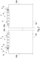
- FIG. 1 a sliding door system 1 according to the invention is shown schematically in a perspective view.
- the sliding door system 1 has a longitudinally extending guide rail 3 in which a door leaf with a Figure 1 not shown drive 4.
- the longitudinal direction is indicated by a double arrow.
- the guide rail 3 has a substantially C-shaped cross-section, with the interior of the guide rail 3 being concealed from the viewer by a cover 5.
- the guide rail 3 forms a track 7 for the running gear 4.
- FIG 2 the door leaf 100 with two drives 4 attached to it is shown in a schematic side view.
- the drives 4 are arranged on an upper edge 100a of the door leaf 100.
- the drive 4 consists of a carriage 9 and a fastening device 11.
- the fastening device 11 is clamped to the door leaf 100.
- the carriage 9 is attached to the fastening device 11 via fastening means not shown.
- the drives 4 are arranged in a mirror image, that is, the carriage is arranged on the side of the fastening device 11 facing the respective outer edge 100b of the door leaf 100.
- the carriages 9 can be arranged very close to the outer edge 100b, whereby a large distance can be created between the carriages 9, whereby a particularly smooth running of the door leaf 100 can be achieved.
- the carriages 9 each have two rollers 13 which are rotatably attached to a roller block 15.
- the roller block 15 is mounted on an axle 17, with the axle 17 located between the two rollers 13.
- the roller block 15 can be plate-shaped.
- the roller block can perform a rocker-like movement via the bearing of the axle 17, so that if one of the rollers 13 threatens to lift off due to an uneven surface, the other roller 13 is pressed in the direction of the track.
- the rollers 13 can roll on the track 7 of the guide rail 3.
- the design of the carriage 9 allows the door leaf 100 to be guided in the guide rail 3 with particular smoothness and ensures that both rollers 13 carry approximately the same load.
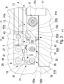
- FIG 3 a locking device 19 of the sliding door system 1 according to the invention is shown schematically in a detailed representation.
- the locking device 19 consists of a locking device 21 and a locking receiver 23.
- the locking mechanism 23 is arranged on the carriage 9 on the side opposite the rollers. As can be seen from Figure 3 As can be seen, the Axle 17 of the roller block 15 for the rollers 13 is secured on this side by means of a nut 17a.
- the locking device 21 forms a structural unit together with a limiting device 25.
- the limiting device 25 limits the travel path of the carriage 4 in the longitudinal direction of the guide rail 3.
- the longitudinal direction of the guide rail 3 is in the Figure 3 represented by a double arrow.
- the limiting device 25 has a stop buffer 27 against which the carriage 9 is pushed when the door leaf 100 is moved into its end position, which is Figure 3 shown.
- the structural unit consisting of the locking device 21 and the limiting device 25 is fastened in the guide rail 3 via a clamping device 29.
- the locking device 21 has a latch 31 which extends essentially in the longitudinal direction of the guide rail 3 and has a hook-shaped section 31a at its end.
- the bolt 31 is pivotably mounted in a vertical plane extending in the longitudinal direction of the guide rail 3.
- the bolt 31 has a pivot bearing 33 which engages the end of the bolt 31 opposite the hook-shaped section 31a.
- the pivot bearing 33 forms a rotation axis for the bolt 31 which runs in a horizontal direction transverse to the longitudinal direction of the guide rail 3.
- the bolt 31 also has a guide device 35 which consists of a guide slot 37 with a bolt inserted into the guide slot 37. The pivoting movement of the bolt 31 is guided via the guide device 35 and limited upwards and downwards.
- the bolt 31 engages in the bolt receptacle 23.
- the bolt receptacle 23 forms a space 41 in which the hook-shaped section 31a and another part of the bolt are located in the end position of the door leaf 100.
- the bolt receptacle 23 has a bolt actuator 43 and a bolt retainer 45, which are spaced apart from one another in the vertical direction. are arranged at a distance.
- the locking device 21 further comprises a locking device 47 which holds the locking device 31 in the locked state of the door leaf 100 in the Figure 3 shown retaining position.
- the bolt 31 In a state in which the bolt 31 has not yet been inserted into the bolt receptacle 23 and the bolt holding device 47 is deactivated, the bolt 31 is in a basic position in which the bolt 31 rests against the bolt 39 with the upper end of the guide slot 37 due to an automatic return force formed by gravity.
- the bolt 31 is first inserted with the hook-shaped section 31a into the opening formed between the bolt actuator 43 and the bolt retainer 45.
- the bolt actuator 43 thereby strikes a first guide surface 31b of the bolt device 21 and, as the door leaf 100 continues to move in the direction of the end position, presses the bolt 31 upwards in the direction of the Figure 3 shown retaining position.
- the latch actuator 43 has a second guide surface 43a which has an arcuate shape, whereby snagging between the latch actuator 43 and latch 31 is avoided.
- the first guide surface 31b has a partially curved profile, with a first section running diagonally at a first angle and a second section running at a second angle.
- the second guide surface 43a of the latch actuator 43 thus initially rests against the first section of the first guide surface 31b and then against the second section.
- the first guide surface 31b is designed in such a way that the latch 31 functions reliably even when the height of the door leaf is adjusted, in which the height of the drive 4 is adjusted relative to the rollers and the roller block and thus a relative adjustment between the latch holder 23 and the latch device 21 also takes place in the vertical direction.
- the latch holding device 47 is designed as a controllable magnet that forms a contact surface 47a.
- the latch 31 is made of a ferromagnetic material. When the magnet is actuated, it attracts the latch 31 in a horizontal direction transverse to the longitudinal direction of the guide rail 3, so that the latch 31 partially rests on the contact surface 47a of the magnet. This creates a frictional connection between the magnet and the latch 31, so that the latch cannot return to the home position due to the automatic return force.
- the latch holding device 47 can be activated even before the door leaf 100 is closed.
- the latch 31 is then raised by the latch actuator 43 from the basic position into the retaining position despite the holding force of the latch holding device 47 and is then held in the retaining position by the latch holding device 47.
- the activation of the latch holding device 47 before the door leaf 100 is closed has the advantage that the locking process of the door leaf 100 can be initiated regardless of its position, ensuring that the door leaf 100 is locked after the next movement into its closed position.
- the latch 31 has an elongated hole 49 opposite the magnet, so that when the magnet is actuated, only part of the contact surface 47a of the magnet rests against the latch 31. This prevents excessive residual magnetism from remaining in the latch 31 after the magnet, which can be a pot magnet, for example, is switched off, which could lead to a delay in the release of the latch 31.
- the latch actuator 43 and the latch retainer 45 are designed as projections which extend in a horizontal direction transverse to the longitudinal direction of the guide rail 3.
- the latch actuator 43 and the latch retainer 45 are opposite a longitudinal direction of the latch receptacle 23 and thus in The horizontally extending central plane of the latch holder 23 extending in the longitudinal direction of the guide rail 3 is formed symmetrically.
- the carriage 9 also has a symmetry with respect to its central plane. As a result, the carriage 9 with the latch holder 23 can also be rotated by 180° and arranged at another end of the door leaf 100 or at another door leaf.
- the space 41 has a free space 41a in the longitudinal direction of the guide rail that extends beyond the bolt 31 in the retaining position. This extends horizontally over a length X that is greater than the maximum spring travel of the elastic stop buffer 27. This ensures that even if the carriage 9 hits the elastic stop buffer 27 at high speed, where the stop buffer 27 compresses, the bolt 31 does not strike the end of the space 41.
- the bolt retainer 45 has a bolt contact surface 45a which, on the side of the bolt retainer 45 facing away from the bolt device 21, extends obliquely in the longitudinal direction of the bolt receptacle 23 away from the bolt device 21 and in the direction of the bolt actuator 43, in Figure 3 i.e., runs diagonally downwards.
- the hook-shaped section 31a has a locking surface 31c which runs diagonally in essentially the same direction in the retaining position of the bolt 31. If the door leaf 100 is moved in the direction of the opening position in the retaining position of the bolt 31 in the locked state, in which the bolt holding device holds the bolt in the retaining position, the locking surface 31c strikes the bolt contact surface 45a. Due to the diagonal course, the bolt retainer 45 is prevented from pressing the bolt 31 downwards in the direction of its basic position.
- an inclined surface 45b is arranged, which runs obliquely in the longitudinal direction of the latch receptacle 23 away from the latch device 21 and in the direction of the latch actuator 43.
- the inclined surface 45b can be parallel to the Bolt contact surface 45a.
- the locking device 19 of the sliding door system 1 has the advantage that for the locking process of the locking device 19, only the bolt holding device 47 has to be actuated, which attracts the bolt 31 and holds it in the retaining position.
- the bolt holding device therefore does not have to cause any movement of the bolt 31. Rather, the movement of the bolt 31 is caused by the movement of the door leaf 100 or the automatic return force. This keeps the technical complexity of the locking device 21 to a minimum.
Landscapes
- Engineering & Computer Science (AREA)
- Mechanical Engineering (AREA)
- Power-Operated Mechanisms For Wings (AREA)
- Lock And Its Accessories (AREA)
Claims (13)
- Système de porte coulissante (1) doté d'au moins une glissière (3) s'étendant dans une direction longitudinale et d'un battant de porte (100) guidé sur celle-ci par au moins un chariot (4), dans lequel le chariot (4) est fixé à un bord supérieur (100a) du battant de porte (100), et doté d'un dispositif de fermeture (19) destiné à clore le battant de porte (100) dans une position fermée, dans lequel le dispositif de fermeture (19) comporte un dispositif de verrou (21) doté d'un loquet (31), dans lequel le dispositif de fermeture (19) comporte une gâche (23), dans lequel la gâche (23) comporte un actionneur de loquet (43) et une retenue de loquet (45) située à distance de l'actionneur de loquet (43), dans lequel le loquet (31) peut s'insérer entre l'actionneur de loquet (43) et la retenue de loquet (45) en cas de fermeture du battant de porte (100)
caractérisé en ce que l'actionneur de loquet (43) guide le loquet (31) dans une position de retenue contre une force de rappel automatique en cas de fermeture du battant de porte (100), dans lequel le loquet (31), en position de retenue, s'engage dans la retenue de loquet (45), dans lequel le dispositif de verrou (21) comporte un dispositif de maintien de loquet (47), lequel maintient le loquet (31) en position de retenue dans l'état clos du dispositif de fermeture (19) et dans lequel le battant de porte (100) peut être clos par un actionnement du dispositif de maintien de loquet (47). - Système de porte coulissante selon la revendication 1, caractérisé en ce que l'actionneur de loquet (43) guide le loquet (31) hors de la position de retenue et vers une position de base en cas d'ouverture du battant de porte (100) dans l'état fermé du dispositif de fermeture (19), dans lequel la force de rappel pousse le loquet (31) contre l'actionneur de loquet (43).
- Système de porte coulissante selon la revendication 1 ou 2, caractérisé en ce que le loquet (31) comporte un palier tournant et l'actionneur de loquet (43) guide le loquet (31) dans une course de pivotement.
- Système de porte coulissante selon l'une des revendications 1 à 3, caractérisé en ce que le dispositif de maintien de loquet (47) est réalisé comme aimant commandable et le loquet (31) est constitué au moins en partie d'un matériau ferromagnétique.
- Système de porte coulissante selon la revendication 4, caractérisé en ce que le loquet (31) comporte un trou oblong (49), dans lequel le trou oblong est disposé à l'opposé de l'aimant.
- Système de porte coulissante selon l'une des revendications 1 à 5, caractérisé en ce que le dispositif de verrou (21) est disposé dans la glissière et la gâche (23) est disposée sur le chariot (4) ou sur le battant de porte (100).
- Système de porte coulissante selon la revendication 6, caractérisé en ce que le dispositif de verrou (21) est fixé à un dispositif de délimitation (25) destiné à délimiter la course du battant de porte (100).
- Système de porte coulissante selon l'une des revendications 1 à 7, caractérisé en ce que l'actionneur de loquet (43) et la retenue de loquet (45) sont réalisés comme des saillies s'étendant en oblique par rapport à la direction longitudinale de la glissière, de préférence dans la direction horizontale.
- Système de porte coulissante selon l'une des revendications 1 à 8, caractérisé en ce que l'actionneur de loquet (43) et la retenue de loquet (45) sont réalisés comme symétriques par rapport à un plan médian de la gâche (23) s'étendant dans la direction longitudinale de la gâche (23) .
- Système de porte coulissante selon l'une des revendications 1 à 9, caractérisé en ce que la gâche (23) comporte un espace s'étendant dans la direction horizontale depuis l'actionneur de loquet (43) et la retenue de loquet (45), à l'intérieur duquel s'introduit le loquet (31) dans la position de retenue, dans lequel l'espace comporte dans la direction longitudinale de la glissière un espace libre s'étendant au-delà du loquet (31) dans la position de retenue et sur une longueur x dans la direction longitudinale, dans lequel la longueur x est supérieure au débattement maximal d'un tampon de butée élastique (27) pour le battant de porte (100).
- Système de porte coulissante selon l'une des revendications 1 à 10, caractérisé en ce que le loquet (31) comporte une première surface de guidage (31b), laquelle comporte un tracé partiellement recourbé, dans lequel l'actionneur de loquet (43) s'appuie sur la première surface de guidage (31b) lors du guidage du loquet (31).
- Système de porte coulissante selon la revendication 11, caractérisé en ce que l'actionneur de loquet (43) comporte une deuxième surface de guidage (43a), laquelle comporte un tracé en forme d'arc, dans lequel la deuxième surface de guidage (43a) s'appuie sur la première surface de guidage (31b) lors du guidage du loquet (31).
- Système de porte coulissante selon l'une des revendications 1 à 12, caractérisé en ce que la retenue de loquet (45) comporte une surface d'appui de loquet (45a), laquelle s'étend en biais dans la direction longitudinale de la gâche (23) depuis le dispositif de verrou (21) et en direction de l'actionneur de loquet (43), dans lequel le loquet (31) comporte une section en forme de crochet, laquelle comporte une surface de loquet (31c) s'étendant en biais dans la même direction dans la position de retenue du loquet (31).
Applications Claiming Priority (1)
| Application Number | Priority Date | Filing Date | Title |
|---|---|---|---|
| DE102019117401.5A DE102019117401A1 (de) | 2019-06-27 | 2019-06-27 | Schiebetürsystem |
Publications (2)
| Publication Number | Publication Date |
|---|---|
| EP3757325A1 EP3757325A1 (fr) | 2020-12-30 |
| EP3757325B1 true EP3757325B1 (fr) | 2024-09-04 |
Family
ID=71143583
Family Applications (1)
| Application Number | Title | Priority Date | Filing Date |
|---|---|---|---|
| EP20182064.4A Active EP3757325B1 (fr) | 2019-06-27 | 2020-06-24 | Système de porte coulissante |
Country Status (2)
| Country | Link |
|---|---|
| EP (1) | EP3757325B1 (fr) |
| DE (1) | DE102019117401A1 (fr) |
Family Cites Families (8)
| Publication number | Priority date | Publication date | Assignee | Title |
|---|---|---|---|---|
| US489221A (en) * | 1893-01-03 | Sliding-door lock | ||
| US4872287A (en) * | 1988-05-13 | 1989-10-10 | C. Hager & Sons Hinge Manufacturing Company | Latching mechanism for trolley-hung doors |
| DE19510002A1 (de) * | 1995-03-22 | 1996-09-26 | Rahrbach Gmbh | Schiebetürverriegelung |
| DE202007014567U1 (de) * | 2007-10-16 | 2007-12-13 | Häfele GmbH & Co. KG | Dämpfungs- und Einziehvorrichtung |
| DE102011089121B3 (de) * | 2011-12-20 | 2013-01-31 | Geze Gmbh | Verriegelungsvorrichtung für eine Schiebetür |
| DE102012104853A1 (de) * | 2012-06-05 | 2013-12-05 | Dorma Gmbh + Co. Kg | Führungsschienenanordnung |
| DE102013217541A1 (de) * | 2013-09-03 | 2015-03-05 | Gebr. Willach Gmbh | Tragsystem für eine Schiebetür, sowie Schiebetür |
| DE102016217664B3 (de) * | 2016-09-15 | 2017-08-17 | Gebr. Willach Gmbh | Tragsystem für eine Schiebetür |
-
2019
- 2019-06-27 DE DE102019117401.5A patent/DE102019117401A1/de not_active Withdrawn
-
2020
- 2020-06-24 EP EP20182064.4A patent/EP3757325B1/fr active Active
Also Published As
| Publication number | Publication date |
|---|---|
| DE102019117401A1 (de) | 2020-12-31 |
| EP3757325A1 (fr) | 2020-12-30 |
Similar Documents
| Publication | Publication Date | Title |
|---|---|---|
| DE68917202T2 (de) | Öffnungs-/Schliessvorrichtung für eine Tür. | |
| EP2607580B1 (fr) | Dispositif de verrouillage pour une porte coulissante | |
| EP2594713B1 (fr) | Ouverture de porte | |
| DE102009029023A1 (de) | Kraftfahrzeugschloss | |
| EP3156565A1 (fr) | Ouverture de porte | |
| EP3042016B1 (fr) | Ferrure pour porte coulissante | |
| EP3296493B1 (fr) | Système support pour porte coulissante | |
| EP2843169B1 (fr) | Porte coulissante avec système de support | |
| EP0635612B1 (fr) | Dispositif de verrouillage pour porte | |
| EP3757325B1 (fr) | Système de porte coulissante | |
| DE102019111871A1 (de) | Entriegelungsvorrichtung mit Sperrvorrichtung | |
| EP4571020A1 (fr) | Serrure à pêne pivotant | |
| EP2951374A1 (fr) | Pièce coulissante servant à guider une partie de meuble dans un sens de guidage sur une glissière et ferrure de meuble | |
| EP3851621B1 (fr) | Système de porte coulissante | |
| EP4448896B1 (fr) | Dispositif de verrouillage pour porte | |
| EP2695843B1 (fr) | Coupleur de porte avec décharge du verrou de porte palière | |
| EP3208407B1 (fr) | Verrou dote d'un dispositif de securite | |
| EP4042846B1 (fr) | Armoire de distribution comprenant un élément de fermeture précontraint dans une position d'ouverture | |
| EP3167134B1 (fr) | Ferrure pour une porte coulissante | |
| EP3656958B1 (fr) | Entraînement auxiliaire pourvu de dispositif d'amortissement pour un battant de portail motorisée ainsi que portail, dont battant de portail est équipé d'un entraînement auxiliaire contenant un dispositif d'amortissement | |
| EP1702126A2 (fr) | Gache electrique telecommandee | |
| DE10255118B4 (de) | Verriegelungseinrichtung zum Verriegeln des Deckels einer Kassenlade an einem Kassenladenunterteil | |
| DE102006001560B4 (de) | Ruhestromtüröffner | |
| EP4400677B1 (fr) | Serrure, notamment pour portes, avec un pêne pivotant verrouillable | |
| EP3757324B1 (fr) | Système de porte coulissante |
Legal Events
| Date | Code | Title | Description |
|---|---|---|---|
| PUAI | Public reference made under article 153(3) epc to a published international application that has entered the european phase |
Free format text: ORIGINAL CODE: 0009012 |
|
| STAA | Information on the status of an ep patent application or granted ep patent |
Free format text: STATUS: THE APPLICATION HAS BEEN PUBLISHED |
|
| AK | Designated contracting states |
Kind code of ref document: A1 Designated state(s): AL AT BE BG CH CY CZ DE DK EE ES FI FR GB GR HR HU IE IS IT LI LT LU LV MC MK MT NL NO PL PT RO RS SE SI SK SM TR |
|
| AX | Request for extension of the european patent |
Extension state: BA ME |
|
| STAA | Information on the status of an ep patent application or granted ep patent |
Free format text: STATUS: REQUEST FOR EXAMINATION WAS MADE |
|
| 17P | Request for examination filed |
Effective date: 20210629 |
|
| RBV | Designated contracting states (corrected) |
Designated state(s): AL AT BE BG CH CY CZ DE DK EE ES FI FR GB GR HR HU IE IS IT LI LT LU LV MC MK MT NL NO PL PT RO RS SE SI SK SM TR |
|
| STAA | Information on the status of an ep patent application or granted ep patent |
Free format text: STATUS: EXAMINATION IS IN PROGRESS |
|
| 17Q | First examination report despatched |
Effective date: 20230830 |
|
| GRAP | Despatch of communication of intention to grant a patent |
Free format text: ORIGINAL CODE: EPIDOSNIGR1 |
|
| STAA | Information on the status of an ep patent application or granted ep patent |
Free format text: STATUS: GRANT OF PATENT IS INTENDED |
|
| INTG | Intention to grant announced |
Effective date: 20240411 |
|
| P01 | Opt-out of the competence of the unified patent court (upc) registered |
Effective date: 20240424 |
|
| GRAS | Grant fee paid |
Free format text: ORIGINAL CODE: EPIDOSNIGR3 |
|
| GRAA | (expected) grant |
Free format text: ORIGINAL CODE: 0009210 |
|
| STAA | Information on the status of an ep patent application or granted ep patent |
Free format text: STATUS: THE PATENT HAS BEEN GRANTED |
|
| AK | Designated contracting states |
Kind code of ref document: B1 Designated state(s): AL AT BE BG CH CY CZ DE DK EE ES FI FR GB GR HR HU IE IS IT LI LT LU LV MC MK MT NL NO PL PT RO RS SE SI SK SM TR |
|
| REG | Reference to a national code |
Ref country code: GB Ref legal event code: FG4D Free format text: NOT ENGLISH |
|
| REG | Reference to a national code |
Ref country code: CH Ref legal event code: EP |
|
| REG | Reference to a national code |
Ref country code: IE Ref legal event code: FG4D Free format text: LANGUAGE OF EP DOCUMENT: GERMAN |
|
| REG | Reference to a national code |
Ref country code: DE Ref legal event code: R096 Ref document number: 502020009072 Country of ref document: DE |
|
| REG | Reference to a national code |
Ref country code: LT Ref legal event code: MG9D |
|
| REG | Reference to a national code |
Ref country code: NL Ref legal event code: MP Effective date: 20240904 |
|
| PG25 | Lapsed in a contracting state [announced via postgrant information from national office to epo] |
Ref country code: NO Free format text: LAPSE BECAUSE OF FAILURE TO SUBMIT A TRANSLATION OF THE DESCRIPTION OR TO PAY THE FEE WITHIN THE PRESCRIBED TIME-LIMIT Effective date: 20241204 |
|
| PG25 | Lapsed in a contracting state [announced via postgrant information from national office to epo] |
Ref country code: GR Free format text: LAPSE BECAUSE OF FAILURE TO SUBMIT A TRANSLATION OF THE DESCRIPTION OR TO PAY THE FEE WITHIN THE PRESCRIBED TIME-LIMIT Effective date: 20241205 Ref country code: FI Free format text: LAPSE BECAUSE OF FAILURE TO SUBMIT A TRANSLATION OF THE DESCRIPTION OR TO PAY THE FEE WITHIN THE PRESCRIBED TIME-LIMIT Effective date: 20240904 Ref country code: PL Free format text: LAPSE BECAUSE OF FAILURE TO SUBMIT A TRANSLATION OF THE DESCRIPTION OR TO PAY THE FEE WITHIN THE PRESCRIBED TIME-LIMIT Effective date: 20240904 |
|
| PG25 | Lapsed in a contracting state [announced via postgrant information from national office to epo] |
Ref country code: BG Free format text: LAPSE BECAUSE OF FAILURE TO SUBMIT A TRANSLATION OF THE DESCRIPTION OR TO PAY THE FEE WITHIN THE PRESCRIBED TIME-LIMIT Effective date: 20240904 |
|
| PG25 | Lapsed in a contracting state [announced via postgrant information from national office to epo] |
Ref country code: LV Free format text: LAPSE BECAUSE OF FAILURE TO SUBMIT A TRANSLATION OF THE DESCRIPTION OR TO PAY THE FEE WITHIN THE PRESCRIBED TIME-LIMIT Effective date: 20240904 |
|
| PG25 | Lapsed in a contracting state [announced via postgrant information from national office to epo] |
Ref country code: HR Free format text: LAPSE BECAUSE OF FAILURE TO SUBMIT A TRANSLATION OF THE DESCRIPTION OR TO PAY THE FEE WITHIN THE PRESCRIBED TIME-LIMIT Effective date: 20240904 |
|
| PG25 | Lapsed in a contracting state [announced via postgrant information from national office to epo] |
Ref country code: ES Free format text: LAPSE BECAUSE OF FAILURE TO SUBMIT A TRANSLATION OF THE DESCRIPTION OR TO PAY THE FEE WITHIN THE PRESCRIBED TIME-LIMIT Effective date: 20240904 Ref country code: RS Free format text: LAPSE BECAUSE OF FAILURE TO SUBMIT A TRANSLATION OF THE DESCRIPTION OR TO PAY THE FEE WITHIN THE PRESCRIBED TIME-LIMIT Effective date: 20241204 |
|
| PG25 | Lapsed in a contracting state [announced via postgrant information from national office to epo] |
Ref country code: RS Free format text: LAPSE BECAUSE OF FAILURE TO SUBMIT A TRANSLATION OF THE DESCRIPTION OR TO PAY THE FEE WITHIN THE PRESCRIBED TIME-LIMIT Effective date: 20241204 Ref country code: PL Free format text: LAPSE BECAUSE OF FAILURE TO SUBMIT A TRANSLATION OF THE DESCRIPTION OR TO PAY THE FEE WITHIN THE PRESCRIBED TIME-LIMIT Effective date: 20240904 Ref country code: NO Free format text: LAPSE BECAUSE OF FAILURE TO SUBMIT A TRANSLATION OF THE DESCRIPTION OR TO PAY THE FEE WITHIN THE PRESCRIBED TIME-LIMIT Effective date: 20241204 Ref country code: LV Free format text: LAPSE BECAUSE OF FAILURE TO SUBMIT A TRANSLATION OF THE DESCRIPTION OR TO PAY THE FEE WITHIN THE PRESCRIBED TIME-LIMIT Effective date: 20240904 Ref country code: HR Free format text: LAPSE BECAUSE OF FAILURE TO SUBMIT A TRANSLATION OF THE DESCRIPTION OR TO PAY THE FEE WITHIN THE PRESCRIBED TIME-LIMIT Effective date: 20240904 Ref country code: GR Free format text: LAPSE BECAUSE OF FAILURE TO SUBMIT A TRANSLATION OF THE DESCRIPTION OR TO PAY THE FEE WITHIN THE PRESCRIBED TIME-LIMIT Effective date: 20241205 Ref country code: FI Free format text: LAPSE BECAUSE OF FAILURE TO SUBMIT A TRANSLATION OF THE DESCRIPTION OR TO PAY THE FEE WITHIN THE PRESCRIBED TIME-LIMIT Effective date: 20240904 Ref country code: ES Free format text: LAPSE BECAUSE OF FAILURE TO SUBMIT A TRANSLATION OF THE DESCRIPTION OR TO PAY THE FEE WITHIN THE PRESCRIBED TIME-LIMIT Effective date: 20240904 Ref country code: BG Free format text: LAPSE BECAUSE OF FAILURE TO SUBMIT A TRANSLATION OF THE DESCRIPTION OR TO PAY THE FEE WITHIN THE PRESCRIBED TIME-LIMIT Effective date: 20240904 |
|
| PG25 | Lapsed in a contracting state [announced via postgrant information from national office to epo] |
Ref country code: NL Free format text: LAPSE BECAUSE OF FAILURE TO SUBMIT A TRANSLATION OF THE DESCRIPTION OR TO PAY THE FEE WITHIN THE PRESCRIBED TIME-LIMIT Effective date: 20240904 |
|
| PG25 | Lapsed in a contracting state [announced via postgrant information from national office to epo] |
Ref country code: IS Free format text: LAPSE BECAUSE OF FAILURE TO SUBMIT A TRANSLATION OF THE DESCRIPTION OR TO PAY THE FEE WITHIN THE PRESCRIBED TIME-LIMIT Effective date: 20250104 Ref country code: PT Free format text: LAPSE BECAUSE OF FAILURE TO SUBMIT A TRANSLATION OF THE DESCRIPTION OR TO PAY THE FEE WITHIN THE PRESCRIBED TIME-LIMIT Effective date: 20250106 |
|
| PG25 | Lapsed in a contracting state [announced via postgrant information from national office to epo] |
Ref country code: RO Free format text: LAPSE BECAUSE OF FAILURE TO SUBMIT A TRANSLATION OF THE DESCRIPTION OR TO PAY THE FEE WITHIN THE PRESCRIBED TIME-LIMIT Effective date: 20240904 Ref country code: SM Free format text: LAPSE BECAUSE OF FAILURE TO SUBMIT A TRANSLATION OF THE DESCRIPTION OR TO PAY THE FEE WITHIN THE PRESCRIBED TIME-LIMIT Effective date: 20240904 |
|
| PG25 | Lapsed in a contracting state [announced via postgrant information from national office to epo] |
Ref country code: EE Free format text: LAPSE BECAUSE OF FAILURE TO SUBMIT A TRANSLATION OF THE DESCRIPTION OR TO PAY THE FEE WITHIN THE PRESCRIBED TIME-LIMIT Effective date: 20240904 |
|
| PG25 | Lapsed in a contracting state [announced via postgrant information from national office to epo] |
Ref country code: CZ Free format text: LAPSE BECAUSE OF FAILURE TO SUBMIT A TRANSLATION OF THE DESCRIPTION OR TO PAY THE FEE WITHIN THE PRESCRIBED TIME-LIMIT Effective date: 20240904 |
|
| PG25 | Lapsed in a contracting state [announced via postgrant information from national office to epo] |
Ref country code: IT Free format text: LAPSE BECAUSE OF FAILURE TO SUBMIT A TRANSLATION OF THE DESCRIPTION OR TO PAY THE FEE WITHIN THE PRESCRIBED TIME-LIMIT Effective date: 20240904 Ref country code: SK Free format text: LAPSE BECAUSE OF FAILURE TO SUBMIT A TRANSLATION OF THE DESCRIPTION OR TO PAY THE FEE WITHIN THE PRESCRIBED TIME-LIMIT Effective date: 20240904 |
|
| REG | Reference to a national code |
Ref country code: DE Ref legal event code: R097 Ref document number: 502020009072 Country of ref document: DE |
|
| PGFP | Annual fee paid to national office [announced via postgrant information from national office to epo] |
Ref country code: DE Payment date: 20250617 Year of fee payment: 6 |
|
| PG25 | Lapsed in a contracting state [announced via postgrant information from national office to epo] |
Ref country code: DK Free format text: LAPSE BECAUSE OF FAILURE TO SUBMIT A TRANSLATION OF THE DESCRIPTION OR TO PAY THE FEE WITHIN THE PRESCRIBED TIME-LIMIT Effective date: 20240904 |
|
| PLBE | No opposition filed within time limit |
Free format text: ORIGINAL CODE: 0009261 |
|
| STAA | Information on the status of an ep patent application or granted ep patent |
Free format text: STATUS: NO OPPOSITION FILED WITHIN TIME LIMIT |
|
| PGFP | Annual fee paid to national office [announced via postgrant information from national office to epo] |
Ref country code: AT Payment date: 20250616 Year of fee payment: 6 |
|
| 26N | No opposition filed |
Effective date: 20250605 |
|
| PG25 | Lapsed in a contracting state [announced via postgrant information from national office to epo] |
Ref country code: SE Free format text: LAPSE BECAUSE OF FAILURE TO SUBMIT A TRANSLATION OF THE DESCRIPTION OR TO PAY THE FEE WITHIN THE PRESCRIBED TIME-LIMIT Effective date: 20240904 |
|
| PGFP | Annual fee paid to national office [announced via postgrant information from national office to epo] |
Ref country code: CH Payment date: 20250701 Year of fee payment: 6 |
|
| PG25 | Lapsed in a contracting state [announced via postgrant information from national office to epo] |
Ref country code: MC Free format text: LAPSE BECAUSE OF FAILURE TO SUBMIT A TRANSLATION OF THE DESCRIPTION OR TO PAY THE FEE WITHIN THE PRESCRIBED TIME-LIMIT Effective date: 20240904 |
|
| PG25 | Lapsed in a contracting state [announced via postgrant information from national office to epo] |
Ref country code: LU Free format text: LAPSE BECAUSE OF NON-PAYMENT OF DUE FEES Effective date: 20250624 |
|
| GBPC | Gb: european patent ceased through non-payment of renewal fee |
Effective date: 20250624 |
|
| REG | Reference to a national code |
Ref country code: BE Ref legal event code: MM Effective date: 20250630 |
|
| PG25 | Lapsed in a contracting state [announced via postgrant information from national office to epo] |
Ref country code: GB Free format text: LAPSE BECAUSE OF NON-PAYMENT OF DUE FEES Effective date: 20250624 |
|
| PG25 | Lapsed in a contracting state [announced via postgrant information from national office to epo] |
Ref country code: IE Free format text: LAPSE BECAUSE OF NON-PAYMENT OF DUE FEES Effective date: 20250624 |
|
| PG25 | Lapsed in a contracting state [announced via postgrant information from national office to epo] |
Ref country code: BE Free format text: LAPSE BECAUSE OF NON-PAYMENT OF DUE FEES Effective date: 20250630 |
|
| PG25 | Lapsed in a contracting state [announced via postgrant information from national office to epo] |
Ref country code: FR Free format text: LAPSE BECAUSE OF NON-PAYMENT OF DUE FEES Effective date: 20250630 |