EP3851626A1 - Buse d'extrusion, procédé d'extrusion et utilisation de la buse d'extrusion - Google Patents
Buse d'extrusion, procédé d'extrusion et utilisation de la buse d'extrusion Download PDFInfo
- Publication number
- EP3851626A1 EP3851626A1 EP20152099.6A EP20152099A EP3851626A1 EP 3851626 A1 EP3851626 A1 EP 3851626A1 EP 20152099 A EP20152099 A EP 20152099A EP 3851626 A1 EP3851626 A1 EP 3851626A1
- Authority
- EP
- European Patent Office
- Prior art keywords
- extrusion nozzle
- extrusion
- head
- openings
- nozzle head
- Prior art date
- Legal status (The legal status is an assumption and is not a legal conclusion. Google has not performed a legal analysis and makes no representation as to the accuracy of the status listed.)
- Withdrawn
Links
Images


Classifications
-
- B—PERFORMING OPERATIONS; TRANSPORTING
- B29—WORKING OF PLASTICS; WORKING OF SUBSTANCES IN A PLASTIC STATE IN GENERAL
- B29C—SHAPING OR JOINING OF PLASTICS; SHAPING OF MATERIAL IN A PLASTIC STATE, NOT OTHERWISE PROVIDED FOR; AFTER-TREATMENT OF THE SHAPED PRODUCTS, e.g. REPAIRING
- B29C48/00—Extrusion moulding, i.e. expressing the moulding material through a die or nozzle which imparts the desired form; Apparatus therefor
- B29C48/25—Component parts, details or accessories; Auxiliary operations
- B29C48/30—Extrusion nozzles or dies
- B29C48/3001—Extrusion nozzles or dies characterised by the material or their manufacturing process
- B29C48/3003—Materials, coating or lining therefor
-
- B—PERFORMING OPERATIONS; TRANSPORTING
- B29—WORKING OF PLASTICS; WORKING OF SUBSTANCES IN A PLASTIC STATE IN GENERAL
- B29C—SHAPING OR JOINING OF PLASTICS; SHAPING OF MATERIAL IN A PLASTIC STATE, NOT OTHERWISE PROVIDED FOR; AFTER-TREATMENT OF THE SHAPED PRODUCTS, e.g. REPAIRING
- B29C48/00—Extrusion moulding, i.e. expressing the moulding material through a die or nozzle which imparts the desired form; Apparatus therefor
- B29C48/16—Articles comprising two or more components, e.g. co-extruded layers
- B29C48/18—Articles comprising two or more components, e.g. co-extruded layers the components being layers
-
- B—PERFORMING OPERATIONS; TRANSPORTING
- B29—WORKING OF PLASTICS; WORKING OF SUBSTANCES IN A PLASTIC STATE IN GENERAL
- B29C—SHAPING OR JOINING OF PLASTICS; SHAPING OF MATERIAL IN A PLASTIC STATE, NOT OTHERWISE PROVIDED FOR; AFTER-TREATMENT OF THE SHAPED PRODUCTS, e.g. REPAIRING
- B29C48/00—Extrusion moulding, i.e. expressing the moulding material through a die or nozzle which imparts the desired form; Apparatus therefor
- B29C48/25—Component parts, details or accessories; Auxiliary operations
- B29C48/266—Means for allowing relative movements between the apparatus parts, e.g. for twisting the extruded article or for moving the die along a surface to be coated
-
- B—PERFORMING OPERATIONS; TRANSPORTING
- B29—WORKING OF PLASTICS; WORKING OF SUBSTANCES IN A PLASTIC STATE IN GENERAL
- B29C—SHAPING OR JOINING OF PLASTICS; SHAPING OF MATERIAL IN A PLASTIC STATE, NOT OTHERWISE PROVIDED FOR; AFTER-TREATMENT OF THE SHAPED PRODUCTS, e.g. REPAIRING
- B29C48/00—Extrusion moulding, i.e. expressing the moulding material through a die or nozzle which imparts the desired form; Apparatus therefor
- B29C48/25—Component parts, details or accessories; Auxiliary operations
- B29C48/30—Extrusion nozzles or dies
- B29C48/345—Extrusion nozzles comprising two or more adjacently arranged ports, for simultaneously extruding multiple strands, e.g. for pelletising
-
- E—FIXED CONSTRUCTIONS
- E06—DOORS, WINDOWS, SHUTTERS, OR ROLLER BLINDS IN GENERAL; LADDERS
- E06B—FIXED OR MOVABLE CLOSURES FOR OPENINGS IN BUILDINGS, VEHICLES, FENCES OR LIKE ENCLOSURES IN GENERAL, e.g. DOORS, WINDOWS, BLINDS, GATES
- E06B3/00—Window sashes, door leaves, or like elements for closing wall or like openings; Layout of fixed or moving closures, e.g. windows in wall or like openings; Features of rigidly-mounted outer frames relating to the mounting of wing frames
- E06B3/66—Units comprising two or more parallel glass or like panes permanently secured together
- E06B3/673—Assembling the units
- E06B3/67339—Working the edges of already assembled units
- E06B3/67343—Filling or covering the edges with synthetic hardenable substances
- E06B3/67347—Filling or covering the edges with synthetic hardenable substances by extrusion techniques
-
- B—PERFORMING OPERATIONS; TRANSPORTING
- B33—ADDITIVE MANUFACTURING TECHNOLOGY
- B33Y—ADDITIVE MANUFACTURING, i.e. MANUFACTURING OF THREE-DIMENSIONAL [3D] OBJECTS BY ADDITIVE DEPOSITION, ADDITIVE AGGLOMERATION OR ADDITIVE LAYERING, e.g. BY 3D PRINTING, STEREOLITHOGRAPHY OR SELECTIVE LASER SINTERING
- B33Y80/00—Products made by additive manufacturing
-
- E—FIXED CONSTRUCTIONS
- E06—DOORS, WINDOWS, SHUTTERS, OR ROLLER BLINDS IN GENERAL; LADDERS
- E06B—FIXED OR MOVABLE CLOSURES FOR OPENINGS IN BUILDINGS, VEHICLES, FENCES OR LIKE ENCLOSURES IN GENERAL, e.g. DOORS, WINDOWS, BLINDS, GATES
- E06B3/00—Window sashes, door leaves, or like elements for closing wall or like openings; Layout of fixed or moving closures, e.g. windows in wall or like openings; Features of rigidly-mounted outer frames relating to the mounting of wing frames
- E06B3/66—Units comprising two or more parallel glass or like panes permanently secured together
- E06B3/673—Assembling the units
- E06B3/67391—Apparatus travelling around the periphery of the pane or the unit
Definitions
- the invention relates to an extrusion nozzle, a method for extrusion and the use of the extrusion nozzle.
- glass panes are first joined with a spacer.
- the spacer is not applied directly to the edge of the glass panes, but at a distance from the edge of the glass panes, so that a cavity is created between the glass panes, delimited by the spacer, which is filled with an adhesive or a polymer as a profile strand.
- the extruded profile can be sealed by means of a sliding shoe in such a way that material is prevented from escaping.
- the material overflows at the corners of the glass, so that these areas have to be reworked manually afterwards.
- extrusion nozzles are known, in particular for different purposes. So is from the WO2013 / 091988 A1 an extrusion nozzle for extrusion of a variable profile strand is known.
- the known extrusion nozzle comprises an extrusion nozzle body which extends along a direction of extent, a nozzle opening in the extrusion nozzle body and a slide for regulating a height of the profile strand.
- Such an extrusion nozzle has a comparatively high complexity.
- DE 42 32 554 C1 discloses a method for producing a glass pane provided with a molded frame made of a thermoplastic polymer and a corresponding device. Before the actual extrusion, the glass pane to be processed is placed on a heated forming bed which protrudes beyond the edges of the glass pane. The profile strand produced protrudes over the glass pane according to the mold bed. For this purpose, a nozzle with an angled nozzle attachment can be used, which engages in the gap between the glass pane and a shaped surface of the surface.
- DE 39 30 414 A1 discloses a glass pane with a profiled frame which is produced by extrusion and curing on the pane.
- the object of the invention is to provide an improved extrusion nozzle, and a method for extrusion and a use of the extrusion nozzle are also to be specified.
- the extrusion nozzle according to the invention for applying a profile strand comprises an extrusion nozzle body with an extrusion nozzle head, the extrusion nozzle body being designed on a first side for connection to a connecting element and having the extrusion nozzle head on a second side. At least two extrusion nozzle openings are arranged on an upper side of the extrusion nozzle head. Furthermore, the extrusion nozzle comprises a distributor element which is arranged on the extrusion nozzle head.
- the advantage of the nozzle according to the invention is an improved distribution of the applied material.
- the at least two extrusion nozzle openings are both arranged on the top of the extrusion nozzle head.
- the at least two extrusion nozzle openings can be arranged next to one another or one behind the other in a feed direction of the extrusion nozzle.
- extrusion nozzle, extrusion nozzle head and / or distributor element are in particular formed in one piece or can be firmly connected to one another.
- the extrusion nozzle head expediently has an upper side which comprises at least one upper surface. From this upper surface, two side surfaces extend, which extend essentially parallel to the feed direction, and a rear surface, which is formed essentially perpendicular to the side surfaces. The distance between the two side surfaces forms a width of the extrusion nozzle head, which is selected to be slightly narrower than a gap width for extrusion into a gap, for example between two panes of glass.
- the extrusion nozzle openings expediently have a square or rectangular opening area.
- the extrusion nozzle body can also be firmly connected to the connecting element or be designed in one piece with it.
- the extrusion nozzle body has a curved or cranked shape.
- a cranked shape should be understood to mean a shape which, after a region directed towards the connecting element, has essentially a U-shape perpendicular thereto, wherein the legs of the U can be designed to be of different lengths or the same length.
- the extrusion nozzle is suitable for being introduced with the extrusion nozzle head into a gap between two glass plates in order to carry out the extrusion there.
- the extrusion nozzle has at least three extrusion nozzle openings, the extrusion nozzle openings being arranged in particular in a row. Expediently, exactly three extrusion nozzle openings are arranged in a row which extends perpendicular to the feed direction. An opening cross section of the outer extrusion nozzle openings is expediently smaller than an opening cross section of the extrusion nozzle openings located between them. Thus, with three extrusion nozzle openings, in particular the middle extrusion nozzle opening is larger than the two outer extrusion nozzle openings.
- the ratio of the opening areas can be 1: 1 to 3: 1, preferably 2: 1, between the central extrusion nozzle opening area and the outer extrusion nozzle opening area.
- the extrusion nozzle openings can also be arranged in two rows arranged one behind the other, which extend perpendicular to the feed direction.
- the distributor element is arranged on the extrusion nozzle head in a feed direction and tapers in the feed direction.
- the distributor element has a surface which is connected to the surface of the extrusion nozzle head.
- the surface of the distributor element and the distributor surface of the extrusion nozzle head expediently have an angle ⁇ .
- This angle ⁇ lies in a plane that extends from the feed direction and the surface normal of the top of the extrusion nozzle head, or in the case of a non-planar surface on the top of the extrusion nozzle head a normal of the Section plane, which includes the upper edges of the side surfaces, is formed.
- the angle ⁇ is preferably between 15 ° and 30 °, in particular between 20 ° to 25 °, the angle ⁇ is preferably 22.5 °.
- the distributor element is particularly suitable for pushing extrusion material in front of the nozzle.
- the extrusion nozzle head has an indentation on two opposite sides, which are arranged in particular in a rear region of the extrusion nozzle head in the feed direction. These indentations are expediently arranged in an upper rear area of the side surfaces of the extrusion nozzle head. These indentations serve as material reservoirs and can thus accommodate excess extrusion material.
- a surface of the top of the extrusion nozzle head is flat, concave, convex or roof-shaped.
- the extrusion nozzle body has an identical number of separate channels to the number of extrusion nozzle openings, with the channels on the first side of the extrusion nozzle body in particular having the cross section of a segment of a circle and the cross section changing along the extrusion nozzle body to the cross-sectional area of the extrusion nozzle opening.
- the extrusion nozzle can have three extrusion nozzle openings.
- the extrusion nozzle then expediently has three channels which run separately from one another through the extrusion nozzle body. The shape of the channels changes from an inlet shape at the inlet of the channels to the shape of the extrusion nozzle openings.
- the extrusion nozzle is expediently produced using a 3-D printing process or by means of injection molding.
- the extrusion nozzle body is preferably made of metals or temperature-stable plastics, preferably iron, chromium, cobalt, nickel, titanium, manganese, aluminum, chromium, niobium, tungsten, molybdenum, vanadium and / or mixtures or alloys thereof.
- the extrusion nozzle openings preferably have an area within an imaginary rectangle with edge lengths from 5 mm to 50 mm and 2 mm to 20 mm, preferably within an imaginary rectangle with edge lengths 10 mm to 30 mm and 5 mm to 15 mm.
- the exact geometry of the nozzle opening is variable and depends on the later shape of the extruded profile seal.
- the nozzle opening preferably has a maximum diameter (a) of 0.1 cm to 3 cm, preferably 0.5 cm to 2 cm.
- the nozzle opening preferably has a maximum height in cross section of 0.1 cm to 3 cm, preferably 0.5 cm to 2 cm.
- the method according to the invention for extrusion of a profile strand onto a substrate comprises the application of a polymer to a substrate by means of the extrusion nozzle according to the invention.
- the polymer must be pasty and extrudable.
- a thermoplastic polymer preferably polyurethane (PU), is expediently used as the extrusion material.
- the extrusion nozzle according to the invention is used for the extrusion of a profile strand on glass, polymers or metals, in particular on vehicle glazing, building glass glazing or laminated glass.
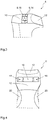
- Fig. 1 shows an embodiment of an extrusion nozzle 2.
- the extrusion nozzle 2 has an extrusion nozzle body 4, which on a first side with a Connecting element 22 is connected and has an extrusion nozzle head 6 on a second side.
- the extrusion nozzle body 4 has a cranked shape.
- the extrusion nozzle body 4 can have a round, rectangular or square cross section.
- the exact shape is adapted in particular to the material to be coated, in particular the gap to be coated or filled.
- the connecting element 22 is adapted to the connection present on the extrusion device. This connecting element 22 can be connected to the extrusion nozzle 2 or is firmly connected.
- the extrusion nozzle head 6 has an upper side 10 on which the extrusion nozzle openings 8 are arranged.
- a distributor element 12 extends from the extrusion nozzle head 6 in the feed direction V.
- the distributor element 12 forms a protrusion or bow on the extrusion die head.
- a surface of the distributor element is tilted by an angle ⁇ to a surface of the extrusion nozzle head.
- the angle ⁇ is in the in Fig. 2 level shown. In the example shown, the angle ⁇ is 20 °.
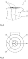
- Fig. 3 shows a view of the top 10 of the extrusion nozzle head 6.
- the extrusion nozzle openings 8 have a rectangular opening area.
- the middle extrusion nozzle opening 16 is larger, in particular larger in a ratio of 2: 1, than the two outer extrusion nozzle openings 14.
- the area of the surface 10 is delimited in the middle area of the extrusion nozzle head 6 by parallel edges.
- the distributor element 12 extends forward therefrom with essentially the same width. On the side facing away from the distributor element 12, the surface becomes narrower.
- indentations 20 to the rear of the extrusion nozzle openings 8 on the side surfaces 18, which indentations 20 extend up to the upper side 10 of the extrusion nozzle head 6. These indentations 20 serve as material reservoirs.
- Fig. 5 it is also shown that the surface in the example is convex, which is what the in Fig. 2 caused the curved transition edge between the surface of the extrusion nozzle head and the surface of the distributor element.
- Fig. 6 shows a view of the connecting element 22. This has three channels 24 in the central area, which extend through the extrusion nozzle body to the extrusion nozzle openings. In the area of the connecting element 22 or on the first side of the extrusion nozzle body 4, the channels are designed as circular segments 24.
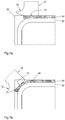
- Fig. 7 shows the application of a profile strand between two glass panes 30.
- the glass panes 30 are provided with a spacer 32, as in FIG Fig. 7d shown, arranged at a predetermined distance from one another, so that a gap with a predetermined width b is formed. Furthermore, the spacer is arranged at a predetermined depth t from an edge of the glass panes 30.
- the extrusion nozzle head 6 can be introduced between the two glass panes 30.
- the width of the extrusion nozzle head 6 is adapted to the gap width b.
- the extrusion nozzle openings 8 are directed towards the spacer 32.
- the distributor element 12 is arranged in the feed direction V of the extrusion nozzle 2 along the gap in front of the extrusion nozzle head 6.
- the extrusion material emerges from the extrusion nozzle openings 8, wherein expediently more extrusion material emerges from the central extrusion nozzle opening or openings 16 than from the outer extrusion nozzle openings 14.
- FIGS Figures 7a to 7c the extrusion nozzle is shown around the corner. In this case, part of the extrusion material with the distributor element 12 is pushed forward in front of the extrusion nozzle 2 and then brought to the desired thickness due to the decreasing distance between the surface and spacer 32. Any excess material can be accommodated in the indentations 20.
- the extrusion profile obtained in this way does not have to be manually reworked in the area of the corners after the extrusion process has ended.
Landscapes
- Engineering & Computer Science (AREA)
- Mechanical Engineering (AREA)
- Manufacturing & Machinery (AREA)
- Civil Engineering (AREA)
- Structural Engineering (AREA)
- Extrusion Moulding Of Plastics Or The Like (AREA)
Priority Applications (1)
| Application Number | Priority Date | Filing Date | Title |
|---|---|---|---|
| EP20152099.6A EP3851626A1 (fr) | 2020-01-16 | 2020-01-16 | Buse d'extrusion, procédé d'extrusion et utilisation de la buse d'extrusion |
Applications Claiming Priority (1)
| Application Number | Priority Date | Filing Date | Title |
|---|---|---|---|
| EP20152099.6A EP3851626A1 (fr) | 2020-01-16 | 2020-01-16 | Buse d'extrusion, procédé d'extrusion et utilisation de la buse d'extrusion |
Publications (1)
| Publication Number | Publication Date |
|---|---|
| EP3851626A1 true EP3851626A1 (fr) | 2021-07-21 |
Family
ID=69174324
Family Applications (1)
| Application Number | Title | Priority Date | Filing Date |
|---|---|---|---|
| EP20152099.6A Withdrawn EP3851626A1 (fr) | 2020-01-16 | 2020-01-16 | Buse d'extrusion, procédé d'extrusion et utilisation de la buse d'extrusion |
Country Status (1)
| Country | Link |
|---|---|
| EP (1) | EP3851626A1 (fr) |
Citations (7)
| Publication number | Priority date | Publication date | Assignee | Title |
|---|---|---|---|---|
| DE2834902A1 (de) * | 1978-08-09 | 1980-02-21 | Reinhardt Gmbh & Co Technik | Isolierglasversiegelungs-automat |
| EP0069021A1 (fr) * | 1981-06-29 | 1983-01-05 | Saint Gobain Vitrage International | Procédé de fabrication d'un vitrage isolant avec protection des arêtes sur le pourtout, dispositif destiné à la mise en oeuvre du procédé, et vitrage fabriqué selon le procédé |
| EP0258801A1 (fr) * | 1986-08-30 | 1988-03-09 | Karl Lenhardt | Procédé de scellement de vitrages isolants rectangulaires |
| DE3930414A1 (de) | 1989-09-12 | 1991-03-14 | Ver Glaswerke Gmbh | Glasscheibe mit einem profilierten rahmen, insbesondere autoglasscheibe, sowie verfahren und vorrichtung zur herstellung einer solchen glasscheibe |
| DE4232554C1 (de) | 1992-09-29 | 1994-01-05 | Ver Glaswerke Gmbh | Verfahren zur Herstellung einer mit einem angeformten Rahmen aus einem thermoplastischen Polymer versehenen Glasscheibe und Vorrichtung zur Durchführung des Verfahrens |
| WO2013091988A1 (fr) | 2011-12-23 | 2013-06-27 | Saint-Gobain Glass France | Filière d'extrusion et procédé de production d'un profilé à variation continue |
| US9556666B1 (en) * | 2015-09-03 | 2017-01-31 | Cardinal Ig Company | Automatic adjustable nozzle systems |
-
2020
- 2020-01-16 EP EP20152099.6A patent/EP3851626A1/fr not_active Withdrawn
Patent Citations (7)
| Publication number | Priority date | Publication date | Assignee | Title |
|---|---|---|---|---|
| DE2834902A1 (de) * | 1978-08-09 | 1980-02-21 | Reinhardt Gmbh & Co Technik | Isolierglasversiegelungs-automat |
| EP0069021A1 (fr) * | 1981-06-29 | 1983-01-05 | Saint Gobain Vitrage International | Procédé de fabrication d'un vitrage isolant avec protection des arêtes sur le pourtout, dispositif destiné à la mise en oeuvre du procédé, et vitrage fabriqué selon le procédé |
| EP0258801A1 (fr) * | 1986-08-30 | 1988-03-09 | Karl Lenhardt | Procédé de scellement de vitrages isolants rectangulaires |
| DE3930414A1 (de) | 1989-09-12 | 1991-03-14 | Ver Glaswerke Gmbh | Glasscheibe mit einem profilierten rahmen, insbesondere autoglasscheibe, sowie verfahren und vorrichtung zur herstellung einer solchen glasscheibe |
| DE4232554C1 (de) | 1992-09-29 | 1994-01-05 | Ver Glaswerke Gmbh | Verfahren zur Herstellung einer mit einem angeformten Rahmen aus einem thermoplastischen Polymer versehenen Glasscheibe und Vorrichtung zur Durchführung des Verfahrens |
| WO2013091988A1 (fr) | 2011-12-23 | 2013-06-27 | Saint-Gobain Glass France | Filière d'extrusion et procédé de production d'un profilé à variation continue |
| US9556666B1 (en) * | 2015-09-03 | 2017-01-31 | Cardinal Ig Company | Automatic adjustable nozzle systems |
Similar Documents
| Publication | Publication Date | Title |
|---|---|---|
| DE3609099C2 (de) | Dichtleiste für Kraftfahrzeuge sowie Verfahren und Vorrichtung zu deren Herstellung | |
| DE68904733T2 (de) | Klebeverbindung einer glasscheibe mit einem metallgegenstand. | |
| DE69209585T2 (de) | Klebefolie und Verfahren zum Verbinden von Elementen mit kleinen Löchern | |
| DE3208749C2 (de) | Scheibenwischer | |
| EP0742762A1 (fr) | Procede de production et de montage d'une vitre avec cadre, notamment dans une partie de vehicule | |
| EP4096851B1 (fr) | Ruban métallique utilisé comme armature pour bande de protection de bord et procédé de fabrication de ce ruban métallique | |
| DE102012106495A1 (de) | Deckel zum Verschließen einer Öffnung eines Fahrzeuges und Verfahren zur Herstellung eines solchen Deckels | |
| DE19604397C1 (de) | Vorrichtung zum Anextrudieren eines rahmenartigen Profilstrangs an eine Glasscheibe | |
| WO2012130867A1 (fr) | Buse de collage comprenant plusieurs ouvertures de sortie | |
| DE102006012373B3 (de) | Breitschlitzdüse und Verfahren zum Auftragen von hochviskosem Material | |
| EP3851626A1 (fr) | Buse d'extrusion, procédé d'extrusion et utilisation de la buse d'extrusion | |
| DE69701929T2 (de) | Tintenstrahldüsenkopf mit einem Trägerkörper | |
| DE202020005597U1 (de) | Extrusionsdüse | |
| EP0441287B1 (fr) | Lame métallique d'insertion pour bandes d'enjolivement et d'étanchéité | |
| WO2003011661A1 (fr) | Balai d'essuie-glace | |
| DE4326179C2 (de) | Verfahren zum Herstellen einer rahmenlosen Verglasung mit geklebter Fensterscheibe | |
| DE2755265C3 (de) | Abdichtungsstreifen bestehend aus einem Bürstenstreifen und einem diesen C-förmig umfassenden Haltestreifen | |
| DE10214337A1 (de) | Verfahren zum Herstellen einer Aufklippbefestigungsanordnung | |
| WO2025045443A1 (fr) | Buse d'extrusion et procédé d'évacuation d'un profil extrudé | |
| DE19632149C1 (de) | Formstempel zum Nachformen eines an einen Gegenstand anextrudierten Profilstrangs | |
| EP3219895B1 (fr) | Système de porte coulissante et vantail coulissant d'un système de porte coulissant | |
| EP3719243B1 (fr) | Connecteur en t, en particulier connecteur de meneaux, pour vitrages collés | |
| DE19516050C2 (de) | Rakel insbesondere für den Siebdruck | |
| DE102010018298A1 (de) | Halteleiste | |
| DE69807153T2 (de) | Verfahren zum Beflocken von profilierten Streifen und beflockte Streifen |
Legal Events
| Date | Code | Title | Description |
|---|---|---|---|
| PUAI | Public reference made under article 153(3) epc to a published international application that has entered the european phase |
Free format text: ORIGINAL CODE: 0009012 |
|
| STAA | Information on the status of an ep patent application or granted ep patent |
Free format text: STATUS: THE APPLICATION HAS BEEN PUBLISHED |
|
| AK | Designated contracting states |
Kind code of ref document: A1 Designated state(s): AL AT BE BG CH CY CZ DE DK EE ES FI FR GB GR HR HU IE IS IT LI LT LU LV MC MK MT NL NO PL PT RO RS SE SI SK SM TR |
|
| STAA | Information on the status of an ep patent application or granted ep patent |
Free format text: STATUS: THE APPLICATION IS DEEMED TO BE WITHDRAWN |
|
| 18D | Application deemed to be withdrawn |
Effective date: 20220122 |