EP3851776A1 - Appareil de réfrigération doté d'un module électronique amovible - Google Patents
Appareil de réfrigération doté d'un module électronique amovible Download PDFInfo
- Publication number
- EP3851776A1 EP3851776A1 EP21151947.5A EP21151947A EP3851776A1 EP 3851776 A1 EP3851776 A1 EP 3851776A1 EP 21151947 A EP21151947 A EP 21151947A EP 3851776 A1 EP3851776 A1 EP 3851776A1
- Authority
- EP
- European Patent Office
- Prior art keywords
- electronics module
- appliance
- enclosure
- recess
- set forth
- Prior art date
- Legal status (The legal status is an assumption and is not a legal conclusion. Google has not performed a legal analysis and makes no representation as to the accuracy of the status listed.)
- Granted
Links
Images







Classifications
-
- F—MECHANICAL ENGINEERING; LIGHTING; HEATING; WEAPONS; BLASTING
- F25—REFRIGERATION OR COOLING; COMBINED HEATING AND REFRIGERATION SYSTEMS; HEAT PUMP SYSTEMS; MANUFACTURE OR STORAGE OF ICE; LIQUEFACTION SOLIDIFICATION OF GASES
- F25D—REFRIGERATORS; COLD ROOMS; ICE-BOXES; COOLING OR FREEZING APPARATUS NOT OTHERWISE PROVIDED FOR
- F25D29/00—Arrangement or mounting of control or safety devices
-
- F—MECHANICAL ENGINEERING; LIGHTING; HEATING; WEAPONS; BLASTING
- F25—REFRIGERATION OR COOLING; COMBINED HEATING AND REFRIGERATION SYSTEMS; HEAT PUMP SYSTEMS; MANUFACTURE OR STORAGE OF ICE; LIQUEFACTION SOLIDIFICATION OF GASES
- F25D—REFRIGERATORS; COLD ROOMS; ICE-BOXES; COOLING OR FREEZING APPARATUS NOT OTHERWISE PROVIDED FOR
- F25D23/00—General constructional features
- F25D23/02—Doors; Covers
- F25D23/028—Details
-
- F—MECHANICAL ENGINEERING; LIGHTING; HEATING; WEAPONS; BLASTING
- F25—REFRIGERATION OR COOLING; COMBINED HEATING AND REFRIGERATION SYSTEMS; HEAT PUMP SYSTEMS; MANUFACTURE OR STORAGE OF ICE; LIQUEFACTION SOLIDIFICATION OF GASES
- F25D—REFRIGERATORS; COLD ROOMS; ICE-BOXES; COOLING OR FREEZING APPARATUS NOT OTHERWISE PROVIDED FOR
- F25D29/00—Arrangement or mounting of control or safety devices
- F25D29/005—Mounting of control devices
-
- G—PHYSICS
- G06—COMPUTING OR CALCULATING; COUNTING
- G06F—ELECTRIC DIGITAL DATA PROCESSING
- G06F3/00—Input arrangements for transferring data to be processed into a form capable of being handled by the computer; Output arrangements for transferring data from processing unit to output unit, e.g. interface arrangements
- G06F3/01—Input arrangements or combined input and output arrangements for interaction between user and computer
- G06F3/03—Arrangements for converting the position or the displacement of a member into a coded form
- G06F3/041—Digitisers, e.g. for touch screens or touch pads, characterised by the transducing means
-
- H—ELECTRICITY
- H05—ELECTRIC TECHNIQUES NOT OTHERWISE PROVIDED FOR
- H05K—PRINTED CIRCUITS; CASINGS OR CONSTRUCTIONAL DETAILS OF ELECTRIC APPARATUS; MANUFACTURE OF ASSEMBLAGES OF ELECTRICAL COMPONENTS
- H05K5/00—Casings, cabinets or drawers for electric apparatus
-
- H—ELECTRICITY
- H05—ELECTRIC TECHNIQUES NOT OTHERWISE PROVIDED FOR
- H05K—PRINTED CIRCUITS; CASINGS OR CONSTRUCTIONAL DETAILS OF ELECTRIC APPARATUS; MANUFACTURE OF ASSEMBLAGES OF ELECTRICAL COMPONENTS
- H05K5/00—Casings, cabinets or drawers for electric apparatus
- H05K5/0017—Casings, cabinets or drawers for electric apparatus with operator interface units
- H05K5/0018—Casings, cabinets or drawers for electric apparatus with operator interface units having an electronic display
-
- H—ELECTRICITY
- H05—ELECTRIC TECHNIQUES NOT OTHERWISE PROVIDED FOR
- H05K—PRINTED CIRCUITS; CASINGS OR CONSTRUCTIONAL DETAILS OF ELECTRIC APPARATUS; MANUFACTURE OF ASSEMBLAGES OF ELECTRICAL COMPONENTS
- H05K5/00—Casings, cabinets or drawers for electric apparatus
- H05K5/02—Details
- H05K5/0204—Mounting supporting structures on the outside of casings
-
- F—MECHANICAL ENGINEERING; LIGHTING; HEATING; WEAPONS; BLASTING
- F25—REFRIGERATION OR COOLING; COMBINED HEATING AND REFRIGERATION SYSTEMS; HEAT PUMP SYSTEMS; MANUFACTURE OR STORAGE OF ICE; LIQUEFACTION SOLIDIFICATION OF GASES
- F25C—PRODUCING, WORKING OR HANDLING ICE
- F25C1/00—Producing ice
- F25C1/22—Construction of moulds; Filling devices for moulds
- F25C1/24—Construction of moulds; Filling devices for moulds for refrigerators, e.g. freezing trays
-
- F—MECHANICAL ENGINEERING; LIGHTING; HEATING; WEAPONS; BLASTING
- F25—REFRIGERATION OR COOLING; COMBINED HEATING AND REFRIGERATION SYSTEMS; HEAT PUMP SYSTEMS; MANUFACTURE OR STORAGE OF ICE; LIQUEFACTION SOLIDIFICATION OF GASES
- F25C—PRODUCING, WORKING OR HANDLING ICE
- F25C2600/00—Control issues
- F25C2600/04—Control means
-
- F—MECHANICAL ENGINEERING; LIGHTING; HEATING; WEAPONS; BLASTING
- F25—REFRIGERATION OR COOLING; COMBINED HEATING AND REFRIGERATION SYSTEMS; HEAT PUMP SYSTEMS; MANUFACTURE OR STORAGE OF ICE; LIQUEFACTION SOLIDIFICATION OF GASES
- F25C—PRODUCING, WORKING OR HANDLING ICE
- F25C5/00—Working or handling ice
- F25C5/20—Distributing ice
- F25C5/24—Distributing ice for storing bins
-
- F—MECHANICAL ENGINEERING; LIGHTING; HEATING; WEAPONS; BLASTING
- F25—REFRIGERATION OR COOLING; COMBINED HEATING AND REFRIGERATION SYSTEMS; HEAT PUMP SYSTEMS; MANUFACTURE OR STORAGE OF ICE; LIQUEFACTION SOLIDIFICATION OF GASES
- F25D—REFRIGERATORS; COLD ROOMS; ICE-BOXES; COOLING OR FREEZING APPARATUS NOT OTHERWISE PROVIDED FOR
- F25D2400/00—General features of, or devices for refrigerators, cold rooms, ice-boxes, or for cooling or freezing apparatus not covered by any other subclass
- F25D2400/36—Visual displays
-
- F—MECHANICAL ENGINEERING; LIGHTING; HEATING; WEAPONS; BLASTING
- F25—REFRIGERATION OR COOLING; COMBINED HEATING AND REFRIGERATION SYSTEMS; HEAT PUMP SYSTEMS; MANUFACTURE OR STORAGE OF ICE; LIQUEFACTION SOLIDIFICATION OF GASES
- F25D—REFRIGERATORS; COLD ROOMS; ICE-BOXES; COOLING OR FREEZING APPARATUS NOT OTHERWISE PROVIDED FOR
- F25D2400/00—General features of, or devices for refrigerators, cold rooms, ice-boxes, or for cooling or freezing apparatus not covered by any other subclass
- F25D2400/36—Visual displays
- F25D2400/361—Interactive visual displays
-
- G—PHYSICS
- G06—COMPUTING OR CALCULATING; COUNTING
- G06F—ELECTRIC DIGITAL DATA PROCESSING
- G06F1/00—Details not covered by groups G06F3/00 - G06F13/00 and G06F21/00
- G06F1/16—Constructional details or arrangements
- G06F1/1613—Constructional details or arrangements for portable computers
- G06F1/1633—Constructional details or arrangements of portable computers not specific to the type of enclosures covered by groups G06F1/1615 - G06F1/1626
- G06F1/1637—Details related to the display arrangement, including those related to the mounting of the display in the housing
- G06F1/1654—Details related to the display arrangement, including those related to the mounting of the display in the housing the display being detachable, e.g. for remote use
-
- H—ELECTRICITY
- H05—ELECTRIC TECHNIQUES NOT OTHERWISE PROVIDED FOR
- H05K—PRINTED CIRCUITS; CASINGS OR CONSTRUCTIONAL DETAILS OF ELECTRIC APPARATUS; MANUFACTURE OF ASSEMBLAGES OF ELECTRICAL COMPONENTS
- H05K5/00—Casings, cabinets or drawers for electric apparatus
- H05K5/02—Details
- H05K5/0247—Electrical details of casings, e.g. terminals, passages for cables or wiring
Definitions
- the present disclosure pertains to a refrigeration appliance, such as an ice maker, a refrigerator, or a freezer, comprising a detachable electronics module.
- refrigeration appliances are in extensive residential and commercial use.
- refrigeration appliances such as refrigerators, freezers and ice makers, use refrigeration devices to maintain the temperature of food in storage, form and hold ice, etc.
- Modern refrigeration appliances often include control systems that use signals from sensors to control various aspects of the appliance.
- Some modern refrigeration appliances include onboard control panels comprising a display and an input device for providing information to and receiving control inputs from a user.
- Certain refrigeration appliances include onboard memories that store information about the usage or performance of the appliances, such as historical data from the sensors.
- a refrigeration appliance comprises an enclosure configured to define an interior space of the appliance.
- the enclosure comprises an enclosure portion that defines an electronics module recess.
- a detachable electronics module comprises a display and a display housing enclosing at least a portion of the display.
- the electronics module is configured to be removably received in the electronics module recess.
- One of the enclosure portion and the display housing defines at least one tab and the other of the enclosure portion and the display housing defines a receiver for each tab. Each tab is removably insertable into the respective receiver to releasably couple the electronics module to the enclosure in the electronics module recess.
- a refrigeration appliance comprises an enclosure configured to define at an interior space of the appliance.
- the enclosure comprises an enclosure portion that defines an electronics module recess.
- a detachable electronics module comprises a display and a display housing enclosing at least a portion of the display.
- the electronics module is configured to be removably received in the electronics module recess.
- a trim piece is configured to be releasably attached to the display housing by a snap-fit connection. The trim piece is configured to retain the electronics module in the electronics module recess when the electronics module is received in the electronics module recess and the frame is attached to the housing by the snap-fit connection.
- a method of using a refrigeration appliance comprises removing a detachable electronics module from an electronics module recess defined in a portion of an enclosure of the appliance without loosening a threaded fastener.
- a data acquisition device is connected to the appliance using a data connector of the appliance that is exposed by said removing the electronics module from the enclosure. Information from the appliance is one of downloaded to the data acquisition device.
- a refrigeration appliance that includes a detachable electronics module.
- a refrigeration appliance includes an electronics module that releasably attaches to an enclosure of a refrigeration appliance without threaded fasteners.
- the electronics module can be selectively removed to, for example, replace the electronics module or another part of the refrigeration appliance; service the electronics module or another part of the refrigeration appliance; and/or connect a data acquisition device to a connector that is hidden by the electronics module to acquire information about the appliance such as usage data.
- the refrigeration appliance comprises an ice maker.
- aspects of the detachable electronics module can be used in combination with other types of appliances (e.g., other types of kitchen appliances such as a cooking appliance, a food preparation or food processing appliance, etc.).
- the term “electronics module” refers to an assembly that includes one or more electronic components (e.g., a display, a memory, a processor, a controller, a speaker) that is at least partially contained in a housing.
- the electronics module comprises a display that is enclosed in a housing comprising a bezel. It is contemplated that displays within the scope of the present disclosure include electroluminescent displays, liquid crystal displays, light-emitting diode displays, plasma displays, quantum dot displays, segment displays, and light indicator panels. Other types of displays can also be used in one or more embodiments.
- a refrigeration appliance comprising a detachable electronics module
- the refrigeration appliance comprises an ice maker.
- the ice maker enclosure receives a portion or all of (i) a refrigeration system including an ice formation device and (ii) a water system for supplying water to the ice formation device for being turned into ice.
- a refrigeration system including an ice formation device
- a water system for supplying water to the ice formation device for being turned into ice.
- other types of refrigeration appliances within the scope of this disclosure will include a refrigeration system at least partially received in an enclosure but lack a water system. Still other types of appliances could include other types of appliance hardware in the enclosure in one or more embodiments.
- FIG. 1 illustrates certain principal components of one embodiment of an ice maker 10 having a refrigeration system and water system.
- the refrigeration system of the ice maker 10 includes a compressor 12, a heat rejecting heat exchanger 14, a refrigerant expansion device 18 for lowering the temperature and pressure of the refrigerant, an ice formation device 20, and a hot gas valve 24.
- the heat rejecting heat exchanger 14 may comprise a condenser for condensing compressed refrigerant vapor discharged from the compressor 12.
- heat rejecting heat exchanger is able to reject heat from the refrigerant without condensing the refrigerant.
- the ice formation device 20 includes an evaporator 21 and a freeze plate 22 thermally coupled to the evaporator 21.
- the evaporator 21 is constructed of serpentine tubing (not shown) as is known in the art.
- the freeze plate 22 contains a large number of pockets (usually in the form of a grid of cells) on its surface where water flowing over the surface can collect.
- Hot gas valve 24 is used, in one or more embodiments, to direct warm refrigerant from the compressor 12 directly to the evaporator 21 to remove or harvest ice cubes from the freeze plate 22 when the ice has reached the desired thickness.
- the refrigerant expansion device 18 can be of any suitable type, including a capillary tube, a thermostatic expansion valve or an electronic expansion valve.
- the ice maker 10 may also include a temperature sensor 26 placed at the outlet of the evaporator 21 to control the refrigerant expansion device 18.
- the ice maker 10 may also include a pressure sensor (not shown) placed at the outlet of the evaporator 21 to control the refrigerant expansion device 18 as is known in the art.
- a condenser fan 15 may be positioned to blow the gaseous cooling medium across the condenser 14. A form of refrigerant cycles through these components via refrigerant lines 28a, 28b, 28c, 28d.
- the water system of the illustrated ice maker 10 includes a sump assembly 60 that comprises a water reservoir or sump 70, a water pump 62, and a water level sensor 90.
- the water system of the ice maker 10 further includes a water supply line (not shown) and a water inlet valve (not shown) for filling sump 70 with water from a water source (not shown).
- the water system of the ice maker 10 further includes a discharge line (not shown) and a discharge valve (not shown; e.g., purge valve, drain valve) disposed thereon for draining water from the tank.
- the water system 14 further comprises a water line 63 and a water distributor 66 (e.g., manifold, pan, tube, etc.) that generally constitute passaging for fluidly connecting the sump 70 to the freeze plate 22.
- a water distributor 66 e.g., manifold, pan, tube, etc.
- the pump 62 pumps water from the sump 70 through the water line 63 and out of the water distributor 66 onto the freeze plate 22.
- the distributor 66 distributes water onto the freeze plate 22 so that the water flows over the pockets of freeze plate and freezes into ice.
- the sump 70 may be positioned below the freeze plate 22 to catch the water coming off of the freeze plate such that the water may be recirculated by water pump 62.
- the water distributor 66 comprises any of the water distributors described in U.S. Patent Application Publication No. 2014/0208792 , which is incorporated herein by reference in its entirety.
- the ice maker 10 may also include a controller 80.
- the controller 80 may be located remote from the ice making device 20 and the sump 70 or may comprise one or more onboard processors, in one or more embodiments.
- the controller 80 may include a processor 82 for controlling the operation of the ice maker 10 including the various components of the refrigeration system and the water system.
- the processor 82 of the controller 80 may include a non-transitory processor-readable medium storing code representing instructions to cause the processor to perform a process.
- the processor 82 may be, for example, a commercially available microprocessor, an application-specific integrated circuit (ASIC) or a combination of ASICs, which are designed to achieve one or more specific functions, or enable one or more specific devices or applications.
- ASIC application-specific integrated circuit
- the controller 80 may be an analog or digital circuit, or a combination of multiple circuits.
- the controller 80 may also include one or more memory components (not shown) for storing data in a form retrievable by the controller.
- the controller 80 can store data in or retrieve data from the one or more memory components.
- the controller 80 may also comprise input/output (I/O) components (not shown) to communicate with and/or control the various components of ice maker 10.
- the controller 80 may receive inputs such as, for example, one or more indications, signals, messages, commands, data, and/or any other information, from the water level sensor 90, a harvest sensor for determining when ice has been harvested (not shown), an electrical power source (not shown), an ice level sensor (not shown), and/or a variety of sensors and/or switches including, but not limited to, pressure transducers, temperature sensors, acoustic sensors, etc.
- the controller 80 may be able to control the compressor 12, the condenser fan 15, the refrigerant expansion device 18, the hot gas valve 24, the water inlet valve, the discharge valve, and/or the water pump 62, for example, by sending, one or more indications, signals, messages, commands, data, and/or any other information to such components.
- the controller 80 is connected to an electronics module 110 that is configured to be detachably coupled to the ice maker 10.
- the illustrated electronics module 110 comprises a touch screen display 112 configured to display information to a user and receive user inputs for controlling the ice maker.
- the electronics module could comprise another type of display and/or another type of user input device.
- the illustrated ice maker 10 further comprises a memory 114 in communication with the controller 80.
- the memory 114 is configured to store information about the ice maker.
- the memory 114 is configured to store usage information about the ice maker based on the indications, signals, messages, commands, data, and/or other information received by the controller 80.
- the memory 114 stores firmware, display animations, unit information, control programs, etc.
- the ice maker 10 comprises a data connector 116 communicatively coupled to the memory 114.
- the data connector 116 is configured for connecting an external data acquisition device 117 (broadly, an external memory device or an external processing device) to the memory 114 to download the information from the memory.
- an external data acquisition device 117 (broadly, an external memory device or an external processing device)
- ice maker 10 is configured so that, when the electronics module 110 is removed or detached from the remainder of the ice maker, the data connector 116 is exposed so that a user can connect the data acquisition device 117 to the data connector 116.
- the information stored on the memory 114 can thus be downloaded to the data acquisition device 117 to perform diagnostics or other functions.
- the data acquisition device 117 comprises a USB memory device.
- the controller 80 is configured to determine whether the USB memory device stores a top level file and take a specified action depending on whether the USB memory device stores a top level file and depending on the file format of any top level file that is identified. For example, if the controller 80 determines that the USB memory device 117 has no top level file, the controller 80 is configured to automatically upload some or all of the information stored on the memory 114 onto the external memory device.
- the information uploaded onto USB memory device 117 includes one or more of an ice maker model number, an ice maker serial number, a cycle history (e.g., stored measured times for completion of freeze and/or harvest cycles), an alarm history, a service history, conservation settings, parameters, and/or any and all data received from sensors associated with the ice maker 10.
- the controller 80 tabulates the data that is uploaded on to the USB memory device 117 in a .CSVfile. If the controller 80 determines that the USB memory device 117 has a top level file in a .BIN format, the controller automatically downloads the file and saves it to the memory 114 as new firmware.
- the controller 80 determines that the USB memory device 116 has a top level file in a .GIF format, the controller will enable the user to replace a graphic display (e.g., a screensaver, advertisement) configured to be displayed via the electronics module 110.
- a graphic display e.g., a screensaver, advertisement
- the user must navigate a memory to replace an existing (e.g., default) graphic display with the graphic display stored in the .GIF file; but in some embodiments, the controller 80 can automatically replace a graphic element that is currently stored in the memory 114 with the one stored in the USB memory device 117.
- an external processing device 117 can be coupled to the ice maker using the connector 116.
- a USB-to-RS485 connector can connect an external computer to the ice maker 110 via the connector 116.
- a user can modify software stored in the memory 114 via the external computer.
- the external computer can execute manufacturer-specific software for modifying the control logic, display parameters, and/or other operating characteristics of the ice maker 110 that are stored in the memory 114.
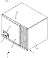
- one or more components of the ice maker 10 may be stored inside of an enclosure 29 of the ice maker 10 that defines an interior space.
- portions or all of the refrigeration system and water system of the ice maker 10 described above can be received in the interior space of the enclosure 29.
- the enclosure 29 is mounted on top of an ice storage bin assembly 30.
- the ice storage bin assembly 30 includes an ice storage bin 31 having a drop zone (not shown) through which ice produced by the ice maker 10 falls. The ice is then stored in a cavity 36 until retrieved.
- the ice storage bin 31 further includes an opening 38 which provides access to the cavity 36 and the ice stored therein.
- the cavity 36, drop zone (not shown), and opening 38 are formed by a left wall 33a, a right wall 33b, a front wall 34, a back wall 35 and a bottom wall (not shown).
- the walls of the ice storage bin 31 may be thermally insulated with various insulating materials including, but not limited to, fiberglass insulation or open- or closed-cell foam comprised, for example, of polystyrene or polyurethane, etc. in order to retard the melting of the ice stored in the ice storage bin 31.
- a door 40 can be opened to provide access to the cavity 36.
- the illustrated enclosure 29 is comprised of a cabinet 120 (broadly, a stationary enclosure portion) and a door 124 (broadly, a movable or removable enclosure portion).
- the door 124 is part of a door assembly 122 that also includes the electronics module 110, as will be described in further detail below.
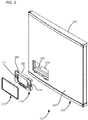
- the door 40 of the ice storage bin assembly 30 is raised so that it partially obscures the door assembly 122, but an exemplary embodiment of the door assembly (including the electronics module 110) is shown more clearly in FIG. 3 .
- the door assembly 122 is movable with respect to the cabinet 120 (e.g., on a hinge) to selectively provide access to the interior space of the ice maker 10.
- a technician may open the door assembly 122 to access the internal components of the ice maker 10 as required for repair or maintenance.
- the door assembly may be opened in other ways, such as by removing the door assembly from the cabinet 120.
- the detachable electronics module 110 is part of the door assembly 122 and configured to be releasably attached to the door 124. More specifically, the illustrated door 124 defines an electronics module recess 150, and the electronics module 110 is configured to be releasably retained in the electronics module recess to form the door assembly 122. As will be explained in further detail below, in one or more embodiments, the electronics module 110 is configured to be retained in the electronics module recess 150 without the use of any threaded fasteners connecting the electronics module to the enclosure 29.
- the door 124 and the electronics module 110 are configured to cover the data connector 116 when the electronics module is received in the electronics module recess 150 and expose the data connector when the electronics module is removed from the electronics module recess so that a user can connect the data acquisition device 117 to the ice maker 10.
- the electronics module recess 150 is formed in the door 124 of the enclosure 29 and the electronics module 110 is configured to be removably attached to the door
- the electronics module recess is formed in another portion of the enclosure (e.g., a wall of the stationary cabinet) or the removable electronics module is otherwise configured to attach to another portion of the enclosure.
- the illustrated door 124 comprises a structural door panel 152 that is configured to be mounted on the cabinet 120 by a hinge 153.
- the structural door panel 152 comprises a single piece of molded rigid plastic that is suitable for supporting the door assembly 122 as it swings on the hinge between an open and a closed position.
- the structural door panel can also have other configurations in certain embodiments.
- the structural door panel 152 includes a depression 154. In the illustrated embodiment, the depression 154 defines a rear portion of the electronics module recess 150, as shown in FIG. 4 .
- the illustrated door 124 further comprises an insulation panel 156 that is configured to extend across the front of the structural door panel 152 to insulate the door, and more broadly, to insulate the front portion of the enclosure 29.
- the insulation panel 156 can be formed from rigid foam or any other suitable insulating material.
- the insulation panel 156 includes an electronic module opening 158. When the insulation panel 156 is supported on the structural door panel 152 in use, the electronics module opening 158 is generally aligned with the depression 154 as shown in FIG. 4 . Thus, in the illustrated embodiment, the electronics module opening 158 of the insulation panel 156 defines a middle portion of the electronics module recess 150.
- the illustrated door 124 further comprises a veneer panel 160 that mounts on structural door panel 152 across the front of the door to provide an aesthetically pleasing appearance.
- the veneer panel 154 is formed from a single piece of stainless steel, though other materials and configurations can be used in other embodiments.
- the veneer panel 160 includes an electronics module opening 162.
- the electronics module opening 162 is generally aligned with the depression 154 in the structural door panel 152 and the other electronics module opening 158 in the insulation panel 156 as shown in FIG. 4 .
- the electronics module opening 162 of the veneer panel 160 defines a front portion of the electronics module recess 150.
- the veneer panel 160 can be attached to the structural door panel 152 in any suitable way.
- the veneer panel 160 attaches to the structural door panel 152 without the use of separate fasteners.
- each of a pair of opposite side margins of the structural door panel 152 defines an elongate groove 164 (the groove along the right side of the door panel is shown in FIG. 5 ) and the veneer panel 160 has a pair of opposite side portions 166 that are generally configured to snap into the grooves to fix the veneer panel onto the door panel.
- the side portions 166 of the veneer panel 160 are generally U-shaped in cross-section.
- the U-shaped side portions 166 extend from respective front corner regions of the structural door panel 152 around the corners and along the sides of the door panel, into the respective grooves 164.
- the veneer panel 160 is configured so that the veneer panel must be resiliently deformed slightly to fit the free cross-sectional end segment of both side portions 166 into the grooves 164. When the free cross-sectional end segments of both side portions 166 are received in the grooves 164, the veneer panel can rebound to hold itself in place on the structural door panel 152.
- the door 124 is configured so that the electronics module recess 150 includes a plurality of receivers 170 along the perimeter of the recess.
- each receiver 170 is configured to receive a tab (broadly, a latching element) of the electronics module 110 therein to retain the electronics module in the electronics module recess.
- the electronics module recess 150 includes two receivers 170 that are spaced apart along the bottom side of the recess and two receivers that are spaced apart along the top side of the recess.
- an electronics module recess can include at least one receiver (e.g., a plurality of receivers) along each of a pair of opposite sides of the recess.
- Other embodiments of electronics module recesses can include other numbers and arrangements of receivers.
- each receiver 170 comprises an L-shaped slot.
- the receivers are generally L-shaped as viewed in plan.
- the bottom receivers 170 are generally L-shaped when viewed in top plan
- the top receivers are generally L-shaped when viewed in bottom plan.
- FIG. 4 only the bottom receivers 170 are shown in such a way as to illustrate the L-shaped slot, but it will be understood that the top receivers have the same configuration.
- each receiver includes a first segment (e.g., the short segment of the L-shaped slot) that extends from a respective opening at the front of the door 124 rearward in a first direction D1.
- Each receiver 170 further includes a second segment that extends laterally from the rear end of the first segment in a second direction D2 (e.g., to the right in FIG. 4 ).
- each L-shaped slot 170 is defined by a notch along the perimeter of the electronics module opening 162 of the veneer panel 160 and a groove formed along the perimeter of the electronics module opening 158 of the insulation panel 156.
- An L-shaped receiver slot can be formed in other ways in one or more embodiments.
- the electronics module recess can include other types of structure (e.g., tabs) for retaining the electronics module therein in certain embodiments.
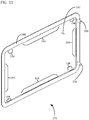
- the door assembly 122 further includes a trim piece 172 that fits around the electronics module 110.
- the electronics module 110 is configured to be removably received in the electronics module recess 150 and includes latching structure that interfaces with the receivers 170 to secure the electronics module in the electronics module recess 150 without any threaded fasteners.
- the trim piece 172 is configured to releasably attach to the electronics module 110 to retain the electronics module in the recess 150 such that the electronics module cannot be removed from the recess without first removing the trim piece from the electronics module.
- the illustrated electronics module comprises a touch-screen LCD display 112 and a display housing 182 enclosing at least a portion of the display.
- other electronics modules can include other types of displays and/or user input devices in one or more embodiments.
- the illustrated display housing 182 comprises a decorative bezel 184 that includes a flange portion that is configured cover a portion of the perimeter of the electronics module recess 150 when the electronics module 110 is attached to the door 124.
- the data connector 116 is integral to the electronics module 110 such that the data connector moves with the electronics module as it is attached to and removed from the door 124.
- the illustrated data connector 116 is mounted directly on the rear portion of the electronics module 110 such that the data connector is covered when the electronics module is attached to the door and exposed when the electronics module is removed from the door.
- a data connector can also be mounted on, or otherwise attached to, the enclosure in another way that results in removal of the electronics module exposing the data connector for being connected to a data acquisition device.
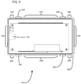
- the display housing 182 further comprises a plurality of tabs 186 that are generally configured for being lockingly received in the receivers 170 when the electronics module 110 is received in the recess 150.
- the electronics module 110 includes two tabs 186 that are spaced apart along the bottom side (broadly, a first side) of the display housing 182 and two tabs that are spaced apart along the top side (broadly, an opposite second side) of the display housing.
- the two pairs of upper and lower tabs 186 correspond to the two pairs of upper and lower receivers 170.
- Each illustrated tab 186 protrudes vertically from the respective one of the top and bottom walls of the display housing 182 and is dimensioned to slot into a respective receiver 170, as will be described in further detail below.
- an electronics module can include at least one tab (e.g., a plurality of tabs) along each of a pair of opposite sides of a display housing in one or more embodiments.
- Other embodiments of electronics modules can include other numbers and arrangements of tabs or other latching elements.
- the bezel 184 of the display housing 182 has a decorative front side and an opposite rear side. Portions of the rear side of the bezel 184 are configured to contact the front of the veneer panel 160 of the door 124 (broadly, the front of the door or exterior surface portion of the enclosure 29) when the electronics module 110 is received in the recess 150.
- the rear side of the bezel 184 also defines a plurality of snap-fit grooves 188 that are configured to attach the trim piece 172 to the display housing 182 by a snap-fit connection, as will be described in further detail below.
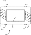
- the illustrated trim piece comprises a frame 190 that defines an opening 192 for receiving the bezel 184 of the electronics module 110.
- the frame 190 is configured to be fitted onto the perimeter of the bezel 184 such that the trim piece 172 extends around and frames the electronics module 110 when the electronics module is attached to the door 124.
- the trim piece 172 is generally configured to be releasably attached to the display housing by a snap-fit connection.
- the illustrated trim piece 170 comprises a plurality of snap-fit protrusions 194 along the inner perimeter of the frame 190 that are shaped and arranged to snap into the snap-fit grooves 188 of the bezel 184 when the frame is fitted to the bezel.
- the snap-fit connection formed by the groves 188 and the protrusions 194 is configured to releasably attach the trim piece onto the electronics module 110.
- the trim piece 172 further comprises a pair of stops 196 that protrude rearwardly from spaced apart locations along one side portion of the frame 190. As shown in FIG. 12 and will be explained in further detail below, the stops 196 are configured to be received in a gap 198 between adjacent, opposing sides of the display housing 182 and the electronics module recess 150 to prevent the electronics module 110 from being removed from the recess without first removing the trim piece 172 from the electronics module.
- the user positions the electronics module in front of the recess 150 with the display 112 facing forward.
- the user aligns the tabs 186 with the front openings of the receivers 170 and then moves the electronics module 110 rearward relative to the door 124 in the first direction D1 such that the tabs pass into the openings at the fronts of the L-shaped receivers.
- each tab 186 When each tab 186 has moved in the first direction D1 until it reaches the rear end portion of the respective receiver 170, the user moves the electronics module laterally of the door 124 in the second direction D2. This positions each tab 186 behind a respective portion of the veneer panel 160 (broadly, behind a portion of the door 124) and thus creates an interlock between the electronics module 110 and the door that partially retains the electronics module in the door. Moving the electronics module 110 laterally the second direction D2 also forms the lateral gap 198 between the side edge of the bezel 184 and the side edge of the electronics module recess 150.
- the user attaches the trim piece 172 to the electronics module (e.g., by snap-fit connection) so that the trim piece stops 196 are received in the lateral gap 198.
- the stops 196 are thus received between the electronics module 110 and the edge of electronics module recess 150 and inhibit movement of the electronics module relative the door 124 in a third direction D3 opposite the second direction D2.
- the trim piece 172 thereby prevents the electronics module 110 from being removed from the door 124 without first removing the trim piece.
- the electronics module 110 may be desirable to periodically remove the electronics module 110 from the door 124.
- a user may wish to replace or repair all or some of the electronics module 110 or another component of the ice maker 10 that is accessible through the electronics module recess 150.
- a user may wish to remove the electronics module 110 from the door 124 to access the data connector 116, for example, for connecting a data acquisition device 117 to the ice maker and downloading usage data.
- the electronics module 110 in the illustrated embodiment the user first disconnects the trim piece 172 from the electronics module. Subsequently, the user moves electronics module 110 relative to the door 124 in the third direction D3 until the tabs 186 align with the front openings of the receivers 170.
- the user moves the electronics module 110 forward relative to the door 124 in a fourth direction D4 ( FIG. 4 ) until the tabs 186 are released from the receivers 170.
- a fourth direction D4 FIG. 4
- no tools are required to remove the electronics module 110 from the recess 150.
- the user is not required to loosen any threaded fasteners to remove the electronics module 110 from the recess 150.
- the user after removing the detachable electronics module 110 from the door 124, the user connects the data acquisition device 117 to the data connector 116 that is exposed by the removal of the electronics module. Subsequently, the user downloads usage information from the appliance (e.g., from memory 114) to the data acquisition device 117 via the data connector 116. In certain embodiments, the user can perform one or more other maintenance or repair tasks (e.g., replacing a part, cleaning a part) in addition to or instead of downloading the usage information. After the desired tasks are completed, the user can reattach the electronics module using the same method described above.
- the electronics module 110 can be repeatably attached to and removed from the door 124; and likewise in certain embodiments, the trim piece 172 can be repeatably attached to and removed from the electronics module.
- the portion of the enclosure 29 defining the electronics module recess 150 defines receivers for receiving tabs 186 of the electronics module 110 therein.
- other arrangements of tabs and receivers can be used.
- the portion of the enclosure defining the electronics module recess includes one or more tabs that are configured to be received in respective receiver(s) defined by the electronics module.
Landscapes
- Engineering & Computer Science (AREA)
- General Engineering & Computer Science (AREA)
- Physics & Mathematics (AREA)
- Mechanical Engineering (AREA)
- Thermal Sciences (AREA)
- Combustion & Propulsion (AREA)
- Chemical & Material Sciences (AREA)
- Microelectronics & Electronic Packaging (AREA)
- Theoretical Computer Science (AREA)
- Human Computer Interaction (AREA)
- General Physics & Mathematics (AREA)
- Devices That Are Associated With Refrigeration Equipment (AREA)
- Cold Air Circulating Systems And Constructional Details In Refrigerators (AREA)
- Casings For Electric Apparatus (AREA)
- Refrigerator Housings (AREA)
Applications Claiming Priority (1)
| Application Number | Priority Date | Filing Date | Title |
|---|---|---|---|
| US16/746,834 US11602059B2 (en) | 2020-01-18 | 2020-01-18 | Refrigeration appliance with detachable electronics module |
Publications (3)
| Publication Number | Publication Date |
|---|---|
| EP3851776A1 true EP3851776A1 (fr) | 2021-07-21 |
| EP3851776C0 EP3851776C0 (fr) | 2023-12-13 |
| EP3851776B1 EP3851776B1 (fr) | 2023-12-13 |
Family
ID=74186554
Family Applications (1)
| Application Number | Title | Priority Date | Filing Date |
|---|---|---|---|
| EP21151947.5A Active EP3851776B1 (fr) | 2020-01-18 | 2021-01-15 | Appareil de réfrigération doté d'un module électronique amovible |
Country Status (9)
| Country | Link |
|---|---|
| US (2) | US11602059B2 (fr) |
| EP (1) | EP3851776B1 (fr) |
| JP (1) | JP2021113667A (fr) |
| KR (1) | KR20210093775A (fr) |
| CN (1) | CN113137823A (fr) |
| AU (1) | AU2021200275B2 (fr) |
| CA (1) | CA3106216A1 (fr) |
| ES (1) | ES2974980T3 (fr) |
| MX (1) | MX2021000578A (fr) |
Families Citing this family (7)
| Publication number | Priority date | Publication date | Assignee | Title |
|---|---|---|---|---|
| EP3655715B8 (fr) * | 2017-07-21 | 2021-03-24 | Unilever IP Holdings B.V. | Armoire de réfrigération équipée d'un dispositif de communication |
| USD1025141S1 (en) | 2020-01-18 | 2024-04-30 | True Manufacturing Co. Inc | Appliance grill |
| USD934924S1 (en) * | 2020-01-18 | 2021-11-02 | True Manufacturing Co., Inc. | Ice maker |
| USD934311S1 (en) * | 2020-01-18 | 2021-10-26 | True Manufacturing Co., Inc. | Ice maker |
| USD1120989S1 (en) * | 2021-02-08 | 2026-03-31 | Qingdao Haier Refrigerator Co., Ltd. | Door body for refrigerator |
| USD941888S1 (en) * | 2021-05-10 | 2022-01-25 | True Manufacturing Company, Inc. | Ice maker |
| KR20240076959A (ko) * | 2022-11-24 | 2024-05-31 | 엘지전자 주식회사 | 식기세척기 |
Citations (6)
| Publication number | Priority date | Publication date | Assignee | Title |
|---|---|---|---|---|
| DE102011082789A1 (de) * | 2011-09-15 | 2013-03-21 | BSH Bosch und Siemens Hausgeräte GmbH | Kältegerät, insbesondere Haushaltskältegerät |
| JP2014044014A (ja) * | 2012-08-28 | 2014-03-13 | Toshiba Corp | 冷蔵庫 |
| US20140208792A1 (en) | 2013-01-30 | 2014-07-31 | True Manufacturing Company, Inc. | Water distributor for an ice maker |
| EP3037757A1 (fr) * | 2014-12-22 | 2016-06-29 | LG Electronics Inc. | Ensemble capteur tactile et porte comportant un tel dispositif |
| EP3264014A1 (fr) * | 2016-06-30 | 2018-01-03 | LG Electronics Inc. | Réfrigérateur |
| US20190383550A1 (en) * | 2018-06-14 | 2019-12-19 | Cse, Inc. | Appliance door handles with integrated graphical displays |
Family Cites Families (174)
| Publication number | Priority date | Publication date | Assignee | Title |
|---|---|---|---|---|
| US2528610A (en) | 1946-03-02 | 1950-11-07 | Vogue Recordings Inc | Sound record disk |
| US2723536A (en) | 1953-03-18 | 1955-11-15 | Sabra E Mason | Apparatus for forming ice cubes |
| US3171266A (en) | 1961-07-06 | 1965-03-02 | Weisco Products Corp | Ice making machine with water distribution means |
| US3430452A (en) | 1966-12-05 | 1969-03-04 | Manitowoc Co | Ice cube making apparatus |
| GB1244831A (en) | 1967-09-29 | 1971-09-02 | Winget Ltd | Ice making apparatus |
| US3788095A (en) | 1971-05-25 | 1974-01-29 | Thiokol Chemical Corp | Spray-freezing apparatus and method |
| US3731496A (en) | 1972-01-31 | 1973-05-08 | Gen Electric | Photoelectric ice level sensor |
| US3812686A (en) | 1973-01-12 | 1974-05-28 | Winget Ltd | Ice making apparatus |
| US3913349A (en) | 1974-03-11 | 1975-10-21 | Ivan L Johnson | Ice maker with swing-out ice cube system |
| US5182925A (en) | 1991-05-13 | 1993-02-02 | Mile High Equipment Company | Integrally formed, modular ice cuber having a stainless steel evaporator and microcontroller |
| JPH08285419A (ja) | 1995-04-10 | 1996-11-01 | Matsushita Refrig Co Ltd | 製氷装置 |
| US5922030A (en) | 1995-12-20 | 1999-07-13 | Nartron Corporation | Method and system for controlling a solid product release mechanism |
| JP3307861B2 (ja) | 1997-10-21 | 2002-07-24 | ホシザキ電機株式会社 | 流下式製氷機 |
| JPH11142033A (ja) | 1997-11-07 | 1999-05-28 | Hoshizaki Electric Co Ltd | 流下式製氷機 |
| JP3342377B2 (ja) | 1997-11-20 | 2002-11-05 | ホシザキ電機株式会社 | 製氷装置 |
| US6196007B1 (en) | 1998-10-06 | 2001-03-06 | Manitowoc Foodservice Group, Inc. | Ice making machine with cool vapor defrost |
| US7284391B2 (en) | 1998-10-06 | 2007-10-23 | Manitowoc Foodservice Companies, Inc. | Pump assembly for an ice making machine |
| US6705107B2 (en) | 1998-10-06 | 2004-03-16 | Manitowoc Foodservice Companies, Inc. | Compact ice making machine with cool vapor defrost |
| JP4293652B2 (ja) | 1998-10-21 | 2009-07-08 | ホシザキ電機株式会社 | 氷ディスペンサー |
| US6209340B1 (en) | 1998-12-07 | 2001-04-03 | Imi Cornelius Inc. | Ice clearing structure for ice makers |
| US6484530B1 (en) | 1999-05-18 | 2002-11-26 | Hoshizaki Denki Kabushiki Kaisha | Flow-down type ice making machinery |
| JP4477723B2 (ja) | 1999-11-25 | 2010-06-09 | ホシザキ電機株式会社 | オーガの製造方法 |
| JP3667593B2 (ja) | 2000-04-21 | 2005-07-06 | ホシザキ電機株式会社 | オープンセルタイプ自動製氷機 |
| JP3868758B2 (ja) | 2000-05-02 | 2007-01-17 | ホシザキ電機株式会社 | 製氷機 |
| US6342840B1 (en) * | 2000-07-25 | 2002-01-29 | Hoshizaki America, Inc. | Service controller for temperature-controlled appliances |
| US6607096B2 (en) | 2000-08-15 | 2003-08-19 | Manitowoc Foodservice Companies, Inc. | Volumetric ice dispensing and measuring device |
| US6324855B1 (en) | 2000-08-29 | 2001-12-04 | Hoshizaki America, Inc. | Proximity ice level detector, proximity detector assembly and methods |
| WO2002023105A1 (fr) | 2000-09-15 | 2002-03-21 | Mile High Equipment Company | Machine a glace silencieuse |
| US6463746B1 (en) | 2000-09-27 | 2002-10-15 | Scotsman Ice Systems | Ice producing machine and method with gear motor monitoring |
| US7925616B2 (en) | 2001-06-19 | 2011-04-12 | Microstrategy, Incorporated | Report system and method using context-sensitive prompt objects |
| US6418736B1 (en) | 2001-06-20 | 2002-07-16 | Hoshizaki America, Inc. | Ice level detector |
| JP3702204B2 (ja) | 2001-08-13 | 2005-10-05 | ホシザキ電機株式会社 | 貯氷庫の氷放出機構部 |
| US6681580B2 (en) | 2001-09-12 | 2004-01-27 | Manitowoc Foodservice Companies, Inc. | Ice machine with assisted harvest |
| CA2463314A1 (fr) | 2001-10-19 | 2003-05-01 | Manitowoc Foodservice Companies, Inc. | Distributeur de boisson a machine a glacons integree |
| US6880358B2 (en) | 2002-03-16 | 2005-04-19 | Manitowoc Foodservice Companies, Inc. | Ice and ice/beverage dispensers |
| US6907744B2 (en) | 2002-03-18 | 2005-06-21 | Manitowoc Foodservice Companies, Inc. | Ice-making machine with improved water curtain |
| US7017355B2 (en) | 2003-03-07 | 2006-03-28 | Scotsman Ice Systems | Ice machine evaporator assemblies with improved heat transfer and method for making same |
| US7062925B2 (en) | 2003-06-24 | 2006-06-20 | Hoshizaki Denki Kabushiki Kaisha | Method of operating auger icemaking machine |
| KR100556774B1 (ko) * | 2003-11-07 | 2006-03-10 | 엘지전자 주식회사 | 텔레비전을 구비한 냉장고 |
| TWI335407B (en) | 2003-12-19 | 2011-01-01 | Hoshizaki Electric Co Ltd | Automatic ice making machine |
| WO2005074562A2 (fr) | 2004-02-03 | 2005-08-18 | Scotsman Ice Systems | Entretien et nettoyage pour glaciere |
| PL1751050T3 (pl) | 2004-04-16 | 2017-06-30 | Manitowoc Foodservice Companies, Inc. | Rozdzielacz dla dystrybutora do napojów |
| JP2006010181A (ja) | 2004-06-24 | 2006-01-12 | Hoshizaki Electric Co Ltd | 自動製氷機の除氷運転方法 |
| US8484935B2 (en) | 2004-07-06 | 2013-07-16 | Daniel D. LeBlanc | Ice bagging system and method |
| JP2006064289A (ja) | 2004-08-26 | 2006-03-09 | Hoshizaki Electric Co Ltd | 冷却装置 |
| US7168262B2 (en) | 2005-03-24 | 2007-01-30 | Hoshizaki Denki Kabushiki Kaisha | Ice making machine |
| US20060261220A1 (en) * | 2005-05-19 | 2006-11-23 | Samsung Electronics Co., Ltd. | Storage compartment with display support |
| US7281386B2 (en) | 2005-06-14 | 2007-10-16 | Manitowoc Foodservice Companies, Inc. | Residential ice machine |
| CA2621217C (fr) | 2005-09-02 | 2013-05-14 | Manitowoc Foodservice Companies, Inc. | Distributeur de glacons/boissons equipe d'un pileur de glace |
| USD540830S1 (en) | 2005-09-29 | 2007-04-17 | Hoshizaki Denki Kabushiki Kaisha | Ice dispenser |
| USD537457S1 (en) | 2005-11-01 | 2007-02-27 | Manitowoc Foodservice Companies, Inc. | Ice machine door |
| USD526338S1 (en) | 2005-11-10 | 2006-08-08 | Manitowoc Foodservice Companies, Inc. | Ice machine |
| US7273990B2 (en) | 2005-11-10 | 2007-09-25 | Hoshizaki Denki Kabushiki Kaisha | Ice storage detection switch |
| US7444828B2 (en) | 2005-11-30 | 2008-11-04 | Hoshizaki Denki Kabushiki Kaisha | Ice discharging structure of ice making mechanism |
| ITMI20060250A1 (it) | 2006-02-10 | 2007-08-11 | Frimont Spa | Macchina per la fabbricazione di ghiaccio |
| USD557716S1 (en) | 2006-03-13 | 2007-12-18 | Hoshizaki Denki Kabushiki Kaisha | Ice machine |
| US8087533B2 (en) | 2006-05-24 | 2012-01-03 | Hoshizaki America, Inc. | Systems and methods for providing a removable sliding access door for an ice storage bin |
| WO2008010454A1 (fr) | 2006-07-20 | 2008-01-24 | Hoshizaki Denki Kabushiki Kaisha | dispositif de versement de boisson |
| JPWO2008026292A1 (ja) | 2006-09-01 | 2010-01-14 | ホシザキ電機株式会社 | 流下式製氷機 |
| WO2008038341A1 (fr) | 2006-09-26 | 2008-04-03 | Hoshizaki Denki Kabushiki Kaisha | Dispositif équipé de mécanisme de refroidissement |
| US9188378B2 (en) | 2006-10-31 | 2015-11-17 | Hoshizaki America, Inc. | Systems and methods for providing an ice storage bin control sensor and housing |
| US8042344B2 (en) | 2006-11-02 | 2011-10-25 | Hoshizaki Denki Kabushiki Kaisha | Automatic ice making machine and operation method therefor |
| US20080123284A1 (en) * | 2006-11-29 | 2008-05-29 | Dell Products, Lp | Server rack door mounted display assembly |
| US7832219B2 (en) | 2006-12-29 | 2010-11-16 | Manitowoc Foodservice Companies, Inc. | Ice making machine and method |
| KR100900287B1 (ko) | 2006-12-29 | 2009-05-29 | 엘지전자 주식회사 | 제빙장치 및 그 제어방법 |
| US7686127B2 (en) * | 2007-01-04 | 2010-03-30 | Whirlpool Corporation | Acoustic chamber as part of adapter or appliance |
| US7765332B2 (en) * | 2007-01-04 | 2010-07-27 | Whirlpool Corporation | Functional adapter for a consumer electronic device |
| US8018716B2 (en) * | 2007-01-04 | 2011-09-13 | Whirlpool Corporation | Adapter for docking a consumer electronic device in discrete orientations |
| JP4934501B2 (ja) | 2007-05-22 | 2012-05-16 | ホシザキ電機株式会社 | 流下式製氷機の散水案内器 |
| JP5097459B2 (ja) | 2007-06-22 | 2012-12-12 | ホシザキ電機株式会社 | 製氷機の運転方法 |
| US7975497B2 (en) | 2007-06-27 | 2011-07-12 | Hoshizaki Denki Kabushiki Kaisha | Refrigeration unit having variable performance compressor operated based on high-pressure side pressure |
| US8136365B2 (en) | 2007-07-02 | 2012-03-20 | Hoshizaki Denki Kabushiki Kaisha | Cooling apparatus having a variable speed compressor with speed limited on the basis of a sensed performance parameter |
| US20090179040A1 (en) | 2008-01-16 | 2009-07-16 | Lancer Partnership, Ltd. | Method and apparatus for an ice level determiner |
| TWD130386S1 (zh) | 2008-03-27 | 2009-08-11 | 星崎電機股份有限公司 | 製冰機 |
| JP5165440B2 (ja) | 2008-03-31 | 2013-03-21 | ホシザキ電機株式会社 | 貯氷庫を装備する製氷機 |
| JP5405168B2 (ja) | 2008-04-01 | 2014-02-05 | ホシザキ電機株式会社 | 流下式製氷機の製氷ユニット |
| CN201197227Y (zh) * | 2008-04-07 | 2009-02-18 | 珠海格力电器股份有限公司 | 一种家用电器 |
| KR101535482B1 (ko) | 2008-04-15 | 2015-07-09 | 엘지전자 주식회사 | 냉장고 제빙기의 만빙 감지 장치 |
| CA2665782A1 (fr) | 2008-05-15 | 2009-11-15 | Manitowoc Foodservice Companies, Inc. | Echangeur de chaleur, en particulier pour distributeur de boissons |
| US8336741B2 (en) | 2008-06-24 | 2012-12-25 | Manitowoc Foodservice Companies, Llc | Front-accessible ice dispenser ice agitation motor |
| JP5380103B2 (ja) | 2009-02-16 | 2014-01-08 | ホシザキ電機株式会社 | 扉体の保持構造 |
| JP5198337B2 (ja) | 2009-03-25 | 2013-05-15 | ホシザキ電機株式会社 | 自動製氷機 |
| EP2312546A3 (fr) * | 2009-10-14 | 2012-04-25 | Whirlpool Corporation | Système modulaire avec appareil et couverte disposant d'une antenne |
| US8528610B2 (en) * | 2009-12-21 | 2013-09-10 | Whirlpool Corporation | Mechanically energized substance communication coupling system |
| US9038410B2 (en) | 2010-06-30 | 2015-05-26 | Manitowoc Foodservice Companies, Llc | Method and system for the continuous or semi-continuous production of flavored ice |
| IN2013MN00301A (fr) | 2010-08-02 | 2015-05-29 | Manitowoc Foodservice Co Inc | |
| CN102346448B (zh) | 2010-08-03 | 2014-11-12 | 曼尼托沃食品服务有限公司 | 用于通知制冰周期启动时延的低压控制 |
| CN202064788U (zh) | 2010-08-04 | 2011-12-07 | 曼尼托沃食品服务有限公司 | 用于储冰盒的门组件 |
| USD649565S1 (en) | 2010-08-04 | 2011-11-29 | Manitowoc Foodservice Companies, Llc | Ice machine |
| MX343412B (es) | 2010-09-24 | 2016-11-04 | Manitowoc Foodservice Companies LLC | Sistema y metodo para obtener ahorros de energia en sistema remoto de bebidas. |
| EP2463603B1 (fr) | 2010-12-10 | 2014-04-30 | Scotsman Group LLC | Rideaux articulés pour machines de fabrication de glaçons |
| US9803907B2 (en) | 2011-02-09 | 2017-10-31 | Manitowoc Foodservice Companies, Llc | Methods and systems for improving and maintaining the cleanliness of ice machines |
| USD668272S1 (en) | 2011-02-10 | 2012-10-02 | Manitowoc Foodservice Companies LLC | Ice machine |
| USD673185S1 (en) | 2011-02-10 | 2012-12-25 | Manitowoc Foodservice Companies, Llc | Ice machine |
| USD669920S1 (en) | 2011-02-10 | 2012-10-30 | Manitowoc Foodservice Companies, Llc | Ice machine |
| USD653682S1 (en) | 2011-02-10 | 2012-02-07 | Manitowoc Foodservice Companies, Llc | Ice machine |
| EP2742308B1 (fr) | 2011-08-12 | 2018-03-14 | Manitowoc Foodservice Companies, LLC | Stockage de glace avec système d'assainissement et procédé d'assainissement de stockage de glace et distributeur de glace |
| BR112014005408A2 (pt) | 2011-09-06 | 2017-03-28 | Manitowoc Foodservice Companies LLC | método e sistema para controlar gotejamento de um distribuidor de bebida por meio de uma válvula de expansão |
| US9052130B2 (en) | 2012-01-13 | 2015-06-09 | Manitowoc Foodservice Companies, Llc | Low refrigerant volume condenser for hydrocarbon refrigerant and ice making machine using same |
| CN202501170U (zh) * | 2012-03-19 | 2012-10-24 | 纬创资通股份有限公司 | 具有快拆功能的显示器 |
| USD692032S1 (en) | 2012-07-11 | 2013-10-22 | Manitowoc Foodservice Companies, Llc | Ice machine |
| USD690743S1 (en) | 2012-07-11 | 2013-10-01 | Manitowoc Foodservice Companies, Llc | Ice machine interface |
| US9351571B2 (en) | 2012-07-11 | 2016-05-31 | Manitowoc Foodservice Companies, Llc | Connection assembly for a base and a cabinet assembly of an ice maker |
| US9625199B2 (en) | 2012-07-11 | 2017-04-18 | Mainitowoc Foodservice Companies, Llc | Methods and apparatus for adjusting ice slab bridge thickness and initiate ice harvest following the freeze cycle |
| US10107538B2 (en) | 2012-09-10 | 2018-10-23 | Hoshizaki America, Inc. | Ice cube evaporator plate assembly |
| US20140137984A1 (en) | 2012-11-21 | 2014-05-22 | True Manufacturing Company, Inc. | Ice maker with bucket filling feature |
| US20140144175A1 (en) | 2012-11-28 | 2014-05-29 | True Manufacturing Company, Inc. | Undercounter ice maker with increased capacity ice storage bin |
| WO2014100368A1 (fr) | 2012-12-21 | 2014-06-26 | Manitowoc Foodservice Companies, Llc | Procédé et système de fixation et d'enlèvement d'une valve de système de moulage de liquide d'un distributeur de boisson |
| WO2014116799A1 (fr) | 2013-01-25 | 2014-07-31 | True Manufacturing Company, Inc. | Machine à glaçons avec bac collecteur extractible |
| US9644879B2 (en) | 2013-01-29 | 2017-05-09 | True Manufacturing Company, Inc. | Apparatus and method for sensing ice thickness and detecting failure modes of an ice maker |
| EP2954273B1 (fr) | 2013-02-05 | 2020-07-29 | True Manufacturing Co., Inc. | Commande d'un appareil frigorifique à l'aide d'un dispositif électronique portable |
| US9643828B2 (en) | 2013-04-08 | 2017-05-09 | Manitowoc Foodservice Companies, Llc | Arcuate multi-dispensing beverage dispenser |
| USD734783S1 (en) | 2013-05-07 | 2015-07-21 | Manitowoc Foodservice Companies, Llc | Ice storage bin and door |
| CA2913017A1 (fr) | 2013-05-20 | 2014-11-27 | Manitowoc Foodservice Companies, Llc | Distributeur hybride de boissons |
| USD734371S1 (en) | 2013-10-09 | 2015-07-14 | Manitowoc Foodservice Companies, Llc | Ice machine having a grill |
| US9389009B2 (en) | 2013-10-31 | 2016-07-12 | Manitowoc Foodservice Companies, Llc | Ice making machine evaporator with joined partition intersections |
| US9243833B2 (en) | 2013-11-05 | 2016-01-26 | General Electric Company | Ice making system for a refrigerator appliance and a method for determining an ice level within an ice bucket |
| EP3087897B1 (fr) | 2013-12-27 | 2020-07-29 | Hoshizaki Corporation | Lave-vaisselle |
| KR102315152B1 (ko) | 2014-01-08 | 2021-10-19 | 트루 매뉴팩쳐링 코., 인크. | 각 얼음 제빙기용 가변 동작점 구성 요소 |
| CN103986750A (zh) * | 2014-04-29 | 2014-08-13 | 华南理工大学 | 基于无线传感网络的集装车辆运输智能安全监控系统 |
| US10059580B2 (en) | 2014-05-06 | 2018-08-28 | Manitowoc Foodservice Companies, Llc | Modular beverage cooling system |
| US20150377538A1 (en) | 2014-06-30 | 2015-12-31 | Manitowoc Foodservice Companies, Llc | Water distribution system for ice-making machine |
| KR20170028949A (ko) | 2014-07-09 | 2017-03-14 | 매니토웍 푸드서비스 컴퍼니즈, 엘엘씨 | 블렌더 블레이드 조립체 |
| AU2015289705A1 (en) | 2014-07-15 | 2017-02-02 | Manitowoc Foodservice Companies, Llc | System and method for a blending containment assembly |
| EP3179892A1 (fr) | 2014-08-14 | 2017-06-21 | Manitowoc Foodservice Companies, LLC | Ensemble de rinçage de mélangeur |
| CN106662387B (zh) | 2014-08-22 | 2019-12-06 | 真实制造有限公司 | 排空制冰机的集水槽以防止有害生物材料的生长 |
| KR102279393B1 (ko) | 2014-08-22 | 2021-07-21 | 삼성전자주식회사 | 냉장고 |
| WO2016053670A1 (fr) | 2014-10-01 | 2016-04-07 | True Manufacturing Co., Inc. | Porte à éclairage périphérique pour unité de réfrigération |
| US10001306B2 (en) | 2014-10-09 | 2018-06-19 | Scottsman Group LLC | Ice-making freezer cleaning |
| US9939186B2 (en) | 2014-10-24 | 2018-04-10 | Scotsman Group Llc | Evaporator assembly for ice-making apparatus and method |
| KR101677334B1 (ko) * | 2014-10-24 | 2016-11-17 | 엘지전자 주식회사 | 냉장고 도어 |
| CA2966212A1 (fr) | 2014-10-31 | 2016-05-06 | First Element Packaging Inc. | Recipient pour recevoir et stocker des fluides |
| WO2016089410A1 (fr) | 2014-12-04 | 2016-06-09 | Manitowoc Foodservice Companies, Llc | Dispositifs permettant une meilleure évacuation des récipients d'ingrédients |
| US20160159520A1 (en) | 2014-12-04 | 2016-06-09 | Manitowoc Foodservice Companies, Llc | Devices for improved evacuation of ingredient containers |
| US20160177022A1 (en) | 2014-12-18 | 2016-06-23 | Axalta Coating Systems Ip Co., Llc | Crosslinking components for electrocoat compositions, electrocoat compositions, and processes for forming a layer of an electrocoat composition on a surface of a substrate |
| GB2533667B (en) | 2014-12-23 | 2017-07-19 | Cambridge Touch Tech Ltd | Pressure-sensitive touch panel |
| CN105485993A (zh) | 2015-03-19 | 2016-04-13 | 斯科茨曼制冰系统(上海)有限公司 | 一种制冰机及使用这种制冰机的制冰方法 |
| JP6384374B2 (ja) | 2015-03-23 | 2018-09-05 | 株式会社デンソー | エジェクタ式冷凍サイクル |
| EP3280960B1 (fr) | 2015-04-06 | 2021-06-30 | True Manufacturing Co., Inc. | Machine à glaçons à caractéristique automatique de détartrage et de désinfection |
| WO2016164165A1 (fr) | 2015-04-09 | 2016-10-13 | True Manufacturing Co., Inc. | Procédés et appareils permettant de commander le cycle de récolte d'une machine à glaçons à l'aide d'un capteur de récolte et d'un capteur de température |
| US10928110B2 (en) | 2015-05-06 | 2021-02-23 | True Manufacturing Co., Inc. | Ice maker with reversing condenser fan motor to maintain clean condenser |
| MX391273B (es) | 2015-05-11 | 2025-03-21 | True Mfg Co Inc | Máquina de hielo con notificación automática para indicar cuándo se requiere mantenimiento. |
| CN107429962A (zh) | 2015-05-14 | 2017-12-01 | 星崎株式会社 | 自动制冰机 |
| ES2769798T3 (es) | 2015-05-22 | 2020-06-29 | Lancer Corp | Métodos y aparato para desinfectar dispensadores |
| CN107709903A (zh) | 2015-06-19 | 2018-02-16 | 曼尼托沃食品服务有限公司 | 用于对冰的生产和分配系统消毒的方法和设备 |
| US20170003062A1 (en) | 2015-07-02 | 2017-01-05 | Manitowoc Foodservice Companies, Llc | Multi-evaporator sequencing apparatus and method |
| GB2544053B (en) | 2015-11-03 | 2021-07-21 | Welbilt Halesowen Ltd | A drinks dispensing system |
| WO2017083359A1 (fr) | 2015-11-09 | 2017-05-18 | Manitowoc Foodservice Companies, Llc | Bloc de montage de soupape de distribution et son procédé d'utilisation |
| US10012345B2 (en) | 2015-12-01 | 2018-07-03 | Lancer Corporation | Method and apparatus for an icemaker adapter |
| DE102015225581A1 (de) | 2015-12-17 | 2017-06-22 | Convotherm Elektrogeräte GmbH | Verfahren zum Betreiben eines gewerblichen Gargeräts |
| ES2991242T3 (es) | 2015-12-21 | 2024-12-03 | True Mfg Co Inc | Máquina de fabricación de hielo con evaporador de doble circuito para un refrigerante de hidrocarburos |
| DE102016204834B4 (de) | 2016-03-23 | 2024-05-29 | Welbilt Deutschland GmbH | Gewerbliches Gargerät |
| US20170299246A1 (en) | 2016-04-14 | 2017-10-19 | Lancer Corporation | Ice chest system |
| DE102016206483B4 (de) | 2016-04-18 | 2026-02-12 | Welbilt Deutschland GmbH | Verfahren zum Feststellen einer Reinigungsnotwendigkeit eines gewerblichen Gargeräts, und gewerbliches Gargerät |
| US10401071B2 (en) | 2016-06-23 | 2019-09-03 | True Manufacturing Co., Inc. | Ice maker with capacitive water level sensing |
| DE102016212162A1 (de) | 2016-07-04 | 2018-01-04 | Convotherm-Elektrogeräte Gmbh | Gewerbliches Gargerät |
| IT201600072581A1 (it) | 2016-07-12 | 2018-01-12 | Scotsman Ice S R L | Macchina per la produzione di ghiaccio. |
| CN109642764B (zh) | 2016-07-15 | 2021-03-30 | 真实制造有限公司 | 制冰机及用于立式喷射型制冰机的排冰装置 |
| EP3491306A4 (fr) | 2016-07-29 | 2020-10-14 | Manitowoc Foodservice Companies, LLC | Système réfrigérant dote d'une conduite de liquide de dérivation d'une ligne de collecte |
| US10107540B2 (en) | 2016-07-29 | 2018-10-23 | Manitowoc Foodservice Companies, Llc | Refrigerant system with liquid line to harvest line bypass |
| US10156393B2 (en) | 2016-09-09 | 2018-12-18 | Haier Us Appliance Solutions, Inc. | Stand-alone ice making appliance |
| US11130658B2 (en) | 2016-11-22 | 2021-09-28 | Manitowoc Crane Companies, Llc | Optical detection and analysis of a counterweight assembly on a crane |
| EP4001801B1 (fr) | 2016-11-23 | 2025-07-09 | True Manufacturing Co., Inc. | Ensemble évaporateur sanitaire |
| WO2018148096A1 (fr) | 2017-02-08 | 2018-08-16 | The Delfield Company, Llc | Petit réservoir de fluide frigorigène destiné à être utilisé avec un système de réfrigération à détendeur thermostatique |
| WO2018147843A1 (fr) | 2017-02-08 | 2018-08-16 | Manitowoc Foodservice Companies, Llc | Pelle à main renforcée |
| DE102017203511A1 (de) | 2017-03-03 | 2018-10-04 | Convotherm-Elektrogeräte Gmbh | Verfahren und Vorrichtung zur gezielten Informationsvermittlung an Gargeräte nutzende Kunden und/oder Gargeräte eines Gargeräte-Herstellers |
| US10731908B2 (en) | 2017-04-26 | 2020-08-04 | Electrolux Home Products, Inc. | Refrigeration appliance with cold air supply for ice maker and ice level sensor |
| DE102017209399A1 (de) | 2017-06-02 | 2018-12-06 | Convotherm-Elektrogeräte Gmbh | Gargerät |
| CN111226084B (zh) | 2018-01-16 | 2022-05-27 | 曼尼托沃食品服务有限公司 | 具有滑动套筒计量装置的分配冰箱 |
| US10480843B2 (en) | 2018-01-19 | 2019-11-19 | Manitowoc Foodservice Companies, Llc | Ice-making machine that utilizes closed-loop harvest control with vibrational feedback |
| WO2019143354A1 (fr) | 2018-01-19 | 2019-07-25 | Manitowoc Foodservice Companies, Llc | Machine de fabrication de glace utilisant une commande de collecte en boucle fermée avec rétroaction vibratoire |
| IT201800002500A1 (it) | 2018-02-08 | 2019-08-08 | Scotsman Ice S R L | Fabbricatore di ghiaccio |
| WO2019164480A1 (fr) | 2018-02-21 | 2019-08-29 | Manitowoc Foodservice Companies, Llc | Support de pelle externe à montage polyvalent |
| CN208487693U (zh) * | 2018-06-14 | 2019-02-12 | 珠海格力电器股份有限公司 | 一种空调用壳体结构、空调外壳及空调器 |
-
2020
- 2020-01-18 US US16/746,834 patent/US11602059B2/en active Active
-
2021
- 2021-01-15 MX MX2021000578A patent/MX2021000578A/es unknown
- 2021-01-15 CA CA3106216A patent/CA3106216A1/fr active Pending
- 2021-01-15 JP JP2021004656A patent/JP2021113667A/ja active Pending
- 2021-01-15 ES ES21151947T patent/ES2974980T3/es active Active
- 2021-01-15 EP EP21151947.5A patent/EP3851776B1/fr active Active
- 2021-01-18 KR KR1020210006738A patent/KR20210093775A/ko not_active Withdrawn
- 2021-01-18 CN CN202110065950.2A patent/CN113137823A/zh active Pending
- 2021-01-18 AU AU2021200275A patent/AU2021200275B2/en not_active Expired - Fee Related
-
2023
- 2023-02-10 US US18/167,400 patent/US12467681B2/en active Active
Patent Citations (6)
| Publication number | Priority date | Publication date | Assignee | Title |
|---|---|---|---|---|
| DE102011082789A1 (de) * | 2011-09-15 | 2013-03-21 | BSH Bosch und Siemens Hausgeräte GmbH | Kältegerät, insbesondere Haushaltskältegerät |
| JP2014044014A (ja) * | 2012-08-28 | 2014-03-13 | Toshiba Corp | 冷蔵庫 |
| US20140208792A1 (en) | 2013-01-30 | 2014-07-31 | True Manufacturing Company, Inc. | Water distributor for an ice maker |
| EP3037757A1 (fr) * | 2014-12-22 | 2016-06-29 | LG Electronics Inc. | Ensemble capteur tactile et porte comportant un tel dispositif |
| EP3264014A1 (fr) * | 2016-06-30 | 2018-01-03 | LG Electronics Inc. | Réfrigérateur |
| US20190383550A1 (en) * | 2018-06-14 | 2019-12-19 | Cse, Inc. | Appliance door handles with integrated graphical displays |
Also Published As
| Publication number | Publication date |
|---|---|
| CA3106216A1 (fr) | 2021-07-18 |
| KR20210093775A (ko) | 2021-07-28 |
| US11602059B2 (en) | 2023-03-07 |
| MX2021000578A (es) | 2021-07-19 |
| EP3851776C0 (fr) | 2023-12-13 |
| AU2021200275B2 (en) | 2024-02-01 |
| JP2021113667A (ja) | 2021-08-05 |
| ES2974980T3 (es) | 2024-07-02 |
| US12467681B2 (en) | 2025-11-11 |
| US20230189453A1 (en) | 2023-06-15 |
| AU2021200275A1 (en) | 2021-08-05 |
| EP3851776B1 (fr) | 2023-12-13 |
| US20210222939A1 (en) | 2021-07-22 |
| CN113137823A (zh) | 2021-07-20 |
Similar Documents
| Publication | Publication Date | Title |
|---|---|---|
| US12467681B2 (en) | Refrigeration appliance with detachable electronics module | |
| US11543161B2 (en) | Ice maker with reversing condenser fan motor to maintain clean condenser | |
| US7878009B2 (en) | Cooling unit with data logging control | |
| US10501972B2 (en) | Refrigeration system and control system therefor | |
| US10126036B2 (en) | Ice maker for dispensing soft ice and related refrigeration appliance | |
| US7573701B2 (en) | Electronic control mount with switch support and light guide | |
| US20240027119A1 (en) | Ice maker | |
| US9021828B2 (en) | Ice box housing assembly and related refrigeration appliance | |
| US20170051966A1 (en) | Injection-molded refrigerator liner with air ducts | |
| CN103868318A (zh) | 冰箱 | |
| US9091473B2 (en) | Float-type ice making assembly and related refrigeration appliance | |
| US20080053119A1 (en) | Cooling Unit With Coded Input Control | |
| US20120125018A1 (en) | Ice dispenser system for a refrigeration appliance, refrigeration appliance, and method of making ice | |
| CN114111139A (zh) | 制冰装置及冰箱 | |
| HK40056936A (en) | Refrigeration appliance with detachable electronics module | |
| CN211552197U (zh) | 一种具有制冰机的冰箱 | |
| CN221648843U (zh) | 冰箱 | |
| US20250305762A1 (en) | Intelligent crisper | |
| KR100404463B1 (ko) | 냉장고용제빙기이상유무제어방법 | |
| KR100562284B1 (ko) | 복합 가전장치 및 그 제어방법 | |
| HK40056934A (en) | Ice maker | |
| KR20080056071A (ko) | 냉장고 | |
| KR200367369Y1 (ko) | 복합 가전장치 | |
| CN112444029A (zh) | 制冰系统的分配器与具有该分配器的冰箱 |
Legal Events
| Date | Code | Title | Description |
|---|---|---|---|
| PUAI | Public reference made under article 153(3) epc to a published international application that has entered the european phase |
Free format text: ORIGINAL CODE: 0009012 |
|
| STAA | Information on the status of an ep patent application or granted ep patent |
Free format text: STATUS: THE APPLICATION HAS BEEN PUBLISHED |
|
| AK | Designated contracting states |
Kind code of ref document: A1 Designated state(s): AL AT BE BG CH CY CZ DE DK EE ES FI FR GB GR HR HU IE IS IT LI LT LU LV MC MK MT NL NO PL PT RO RS SE SI SK SM TR |
|
| STAA | Information on the status of an ep patent application or granted ep patent |
Free format text: STATUS: REQUEST FOR EXAMINATION WAS MADE |
|
| 17P | Request for examination filed |
Effective date: 20220118 |
|
| RBV | Designated contracting states (corrected) |
Designated state(s): AL AT BE BG CH CY CZ DE DK EE ES FI FR GB GR HR HU IE IS IT LI LT LU LV MC MK MT NL NO PL PT RO RS SE SI SK SM TR |
|
| STAA | Information on the status of an ep patent application or granted ep patent |
Free format text: STATUS: EXAMINATION IS IN PROGRESS |
|
| 17Q | First examination report despatched |
Effective date: 20221205 |
|
| GRAP | Despatch of communication of intention to grant a patent |
Free format text: ORIGINAL CODE: EPIDOSNIGR1 |
|
| STAA | Information on the status of an ep patent application or granted ep patent |
Free format text: STATUS: GRANT OF PATENT IS INTENDED |
|
| INTG | Intention to grant announced |
Effective date: 20230705 |
|
| GRAS | Grant fee paid |
Free format text: ORIGINAL CODE: EPIDOSNIGR3 |
|
| GRAA | (expected) grant |
Free format text: ORIGINAL CODE: 0009210 |
|
| STAA | Information on the status of an ep patent application or granted ep patent |
Free format text: STATUS: THE PATENT HAS BEEN GRANTED |
|
| AK | Designated contracting states |
Kind code of ref document: B1 Designated state(s): AL AT BE BG CH CY CZ DE DK EE ES FI FR GB GR HR HU IE IS IT LI LT LU LV MC MK MT NL NO PL PT RO RS SE SI SK SM TR |
|
| REG | Reference to a national code |
Ref country code: GB Ref legal event code: FG4D |
|
| REG | Reference to a national code |
Ref country code: CH Ref legal event code: EP |
|
| REG | Reference to a national code |
Ref country code: DE Ref legal event code: R096 Ref document number: 602021007551 Country of ref document: DE |
|
| REG | Reference to a national code |
Ref country code: IE Ref legal event code: FG4D |
|
| U01 | Request for unitary effect filed |
Effective date: 20231214 |
|
| U07 | Unitary effect registered |
Designated state(s): AT BE BG DE DK EE FI FR IT LT LU LV MT NL PT SE SI Effective date: 20231222 |
|
| U20 | Renewal fee for the european patent with unitary effect paid |
Year of fee payment: 4 Effective date: 20240125 |
|
| PG25 | Lapsed in a contracting state [announced via postgrant information from national office to epo] |
Ref country code: GR Free format text: LAPSE BECAUSE OF FAILURE TO SUBMIT A TRANSLATION OF THE DESCRIPTION OR TO PAY THE FEE WITHIN THE PRESCRIBED TIME-LIMIT Effective date: 20240314 |
|
| PG25 | Lapsed in a contracting state [announced via postgrant information from national office to epo] |
Ref country code: GR Free format text: LAPSE BECAUSE OF FAILURE TO SUBMIT A TRANSLATION OF THE DESCRIPTION OR TO PAY THE FEE WITHIN THE PRESCRIBED TIME-LIMIT Effective date: 20240314 |
|
| PG25 | Lapsed in a contracting state [announced via postgrant information from national office to epo] |
Ref country code: RS Free format text: LAPSE BECAUSE OF FAILURE TO SUBMIT A TRANSLATION OF THE DESCRIPTION OR TO PAY THE FEE WITHIN THE PRESCRIBED TIME-LIMIT Effective date: 20231213 Ref country code: NO Free format text: LAPSE BECAUSE OF FAILURE TO SUBMIT A TRANSLATION OF THE DESCRIPTION OR TO PAY THE FEE WITHIN THE PRESCRIBED TIME-LIMIT Effective date: 20240313 Ref country code: HR Free format text: LAPSE BECAUSE OF FAILURE TO SUBMIT A TRANSLATION OF THE DESCRIPTION OR TO PAY THE FEE WITHIN THE PRESCRIBED TIME-LIMIT Effective date: 20231213 |
|
| PG25 | Lapsed in a contracting state [announced via postgrant information from national office to epo] |
Ref country code: IS Free format text: LAPSE BECAUSE OF FAILURE TO SUBMIT A TRANSLATION OF THE DESCRIPTION OR TO PAY THE FEE WITHIN THE PRESCRIBED TIME-LIMIT Effective date: 20240413 |
|
| REG | Reference to a national code |
Ref country code: ES Ref legal event code: FG2A Ref document number: 2974980 Country of ref document: ES Kind code of ref document: T3 Effective date: 20240702 |
|
| PG25 | Lapsed in a contracting state [announced via postgrant information from national office to epo] |
Ref country code: CZ Free format text: LAPSE BECAUSE OF FAILURE TO SUBMIT A TRANSLATION OF THE DESCRIPTION OR TO PAY THE FEE WITHIN THE PRESCRIBED TIME-LIMIT Effective date: 20231213 |
|
| PG25 | Lapsed in a contracting state [announced via postgrant information from national office to epo] |
Ref country code: SK Free format text: LAPSE BECAUSE OF FAILURE TO SUBMIT A TRANSLATION OF THE DESCRIPTION OR TO PAY THE FEE WITHIN THE PRESCRIBED TIME-LIMIT Effective date: 20231213 |
|
| PG25 | Lapsed in a contracting state [announced via postgrant information from national office to epo] |
Ref country code: SM Free format text: LAPSE BECAUSE OF FAILURE TO SUBMIT A TRANSLATION OF THE DESCRIPTION OR TO PAY THE FEE WITHIN THE PRESCRIBED TIME-LIMIT Effective date: 20231213 Ref country code: SK Free format text: LAPSE BECAUSE OF FAILURE TO SUBMIT A TRANSLATION OF THE DESCRIPTION OR TO PAY THE FEE WITHIN THE PRESCRIBED TIME-LIMIT Effective date: 20231213 Ref country code: RO Free format text: LAPSE BECAUSE OF FAILURE TO SUBMIT A TRANSLATION OF THE DESCRIPTION OR TO PAY THE FEE WITHIN THE PRESCRIBED TIME-LIMIT Effective date: 20231213 Ref country code: IS Free format text: LAPSE BECAUSE OF FAILURE TO SUBMIT A TRANSLATION OF THE DESCRIPTION OR TO PAY THE FEE WITHIN THE PRESCRIBED TIME-LIMIT Effective date: 20240413 Ref country code: CZ Free format text: LAPSE BECAUSE OF FAILURE TO SUBMIT A TRANSLATION OF THE DESCRIPTION OR TO PAY THE FEE WITHIN THE PRESCRIBED TIME-LIMIT Effective date: 20231213 |
|
| PG25 | Lapsed in a contracting state [announced via postgrant information from national office to epo] |
Ref country code: PL Free format text: LAPSE BECAUSE OF FAILURE TO SUBMIT A TRANSLATION OF THE DESCRIPTION OR TO PAY THE FEE WITHIN THE PRESCRIBED TIME-LIMIT Effective date: 20231213 |
|
| PG25 | Lapsed in a contracting state [announced via postgrant information from national office to epo] |
Ref country code: PL Free format text: LAPSE BECAUSE OF FAILURE TO SUBMIT A TRANSLATION OF THE DESCRIPTION OR TO PAY THE FEE WITHIN THE PRESCRIBED TIME-LIMIT Effective date: 20231213 |
|
| REG | Reference to a national code |
Ref country code: CH Ref legal event code: PL |
|
| REG | Reference to a national code |
Ref country code: DE Ref legal event code: R097 Ref document number: 602021007551 Country of ref document: DE |
|
| PG25 | Lapsed in a contracting state [announced via postgrant information from national office to epo] |
Ref country code: MC Free format text: LAPSE BECAUSE OF FAILURE TO SUBMIT A TRANSLATION OF THE DESCRIPTION OR TO PAY THE FEE WITHIN THE PRESCRIBED TIME-LIMIT Effective date: 20231213 |
|
| PLBE | No opposition filed within time limit |
Free format text: ORIGINAL CODE: 0009261 |
|
| STAA | Information on the status of an ep patent application or granted ep patent |
Free format text: STATUS: NO OPPOSITION FILED WITHIN TIME LIMIT |
|
| PG25 | Lapsed in a contracting state [announced via postgrant information from national office to epo] |
Ref country code: CH Free format text: LAPSE BECAUSE OF NON-PAYMENT OF DUE FEES Effective date: 20240131 |
|
| PG25 | Lapsed in a contracting state [announced via postgrant information from national office to epo] |
Ref country code: CH Free format text: LAPSE BECAUSE OF NON-PAYMENT OF DUE FEES Effective date: 20240131 |
|
| 26N | No opposition filed |
Effective date: 20240916 |
|
| PG25 | Lapsed in a contracting state [announced via postgrant information from national office to epo] |
Ref country code: IE Free format text: LAPSE BECAUSE OF NON-PAYMENT OF DUE FEES Effective date: 20240115 |
|
| PG25 | Lapsed in a contracting state [announced via postgrant information from national office to epo] |
Ref country code: IE Free format text: LAPSE BECAUSE OF NON-PAYMENT OF DUE FEES Effective date: 20240115 |
|
| U20 | Renewal fee for the european patent with unitary effect paid |
Year of fee payment: 5 Effective date: 20250127 |
|
| PG25 | Lapsed in a contracting state [announced via postgrant information from national office to epo] |
Ref country code: CY Free format text: LAPSE BECAUSE OF FAILURE TO SUBMIT A TRANSLATION OF THE DESCRIPTION OR TO PAY THE FEE WITHIN THE PRESCRIBED TIME-LIMIT; INVALID AB INITIO Effective date: 20210115 |
|
| PG25 | Lapsed in a contracting state [announced via postgrant information from national office to epo] |
Ref country code: HU Free format text: LAPSE BECAUSE OF FAILURE TO SUBMIT A TRANSLATION OF THE DESCRIPTION OR TO PAY THE FEE WITHIN THE PRESCRIBED TIME-LIMIT; INVALID AB INITIO Effective date: 20210115 |
|
| PG25 | Lapsed in a contracting state [announced via postgrant information from national office to epo] |
Ref country code: TR Free format text: LAPSE BECAUSE OF FAILURE TO SUBMIT A TRANSLATION OF THE DESCRIPTION OR TO PAY THE FEE WITHIN THE PRESCRIBED TIME-LIMIT Effective date: 20231213 |
|
| U20 | Renewal fee for the european patent with unitary effect paid |
Year of fee payment: 6 Effective date: 20260127 |
|
| PGFP | Annual fee paid to national office [announced via postgrant information from national office to epo] |
Ref country code: GB Payment date: 20260127 Year of fee payment: 6 |
|
| PGFP | Annual fee paid to national office [announced via postgrant information from national office to epo] |
Ref country code: ES Payment date: 20260202 Year of fee payment: 6 |