EP3851786A1 - Guidage des matières de fixation métalliques à faible risque de défaillance - Google Patents
Guidage des matières de fixation métalliques à faible risque de défaillance Download PDFInfo
- Publication number
- EP3851786A1 EP3851786A1 EP21161856.6A EP21161856A EP3851786A1 EP 3851786 A1 EP3851786 A1 EP 3851786A1 EP 21161856 A EP21161856 A EP 21161856A EP 3851786 A1 EP3851786 A1 EP 3851786A1
- Authority
- EP
- European Patent Office
- Prior art keywords
- metal pin
- base body
- metal
- stainless steel
- fixing material
- Prior art date
- Legal status (The legal status is an assumption and is not a legal conclusion. Google has not performed a legal analysis and makes no representation as to the accuracy of the status listed.)
- Granted
Links
Images




Classifications
-
- H—ELECTRICITY
- H01—ELECTRIC ELEMENTS
- H01J—ELECTRIC DISCHARGE TUBES OR DISCHARGE LAMPS
- H01J61/00—Gas-discharge or vapour-discharge lamps
- H01J61/02—Details
- H01J61/36—Seals between parts of vessels; Seals for leading-in conductors; Leading-in conductors
- H01J61/366—Seals for leading-in conductors
-
- F—MECHANICAL ENGINEERING; LIGHTING; HEATING; WEAPONS; BLASTING
- F42—AMMUNITION; BLASTING
- F42B—EXPLOSIVE CHARGES, e.g. FOR BLASTING, FIREWORKS, AMMUNITION
- F42B3/00—Blasting cartridges, i.e. case and explosive
- F42B3/10—Initiators therefor
- F42B3/11—Initiators therefor characterised by the material used, e.g. for initiator case or electric leads
-
- A—HUMAN NECESSITIES
- A61—MEDICAL OR VETERINARY SCIENCE; HYGIENE
- A61L—METHODS OR APPARATUS FOR STERILISING MATERIALS OR OBJECTS IN GENERAL; DISINFECTION, STERILISATION OR DEODORISATION OF AIR; CHEMICAL ASPECTS OF BANDAGES, DRESSINGS, ABSORBENT PADS OR SURGICAL ARTICLES; MATERIALS FOR BANDAGES, DRESSINGS, ABSORBENT PADS OR SURGICAL ARTICLES
- A61L27/00—Materials for grafts or prostheses or for coating grafts or prostheses
- A61L27/02—Inorganic materials
- A61L27/025—Other specific inorganic materials not covered by A61L27/04 - A61L27/12
-
- A—HUMAN NECESSITIES
- A61—MEDICAL OR VETERINARY SCIENCE; HYGIENE
- A61L—METHODS OR APPARATUS FOR STERILISING MATERIALS OR OBJECTS IN GENERAL; DISINFECTION, STERILISATION OR DEODORISATION OF AIR; CHEMICAL ASPECTS OF BANDAGES, DRESSINGS, ABSORBENT PADS OR SURGICAL ARTICLES; MATERIALS FOR BANDAGES, DRESSINGS, ABSORBENT PADS OR SURGICAL ARTICLES
- A61L27/00—Materials for grafts or prostheses or for coating grafts or prostheses
- A61L27/02—Inorganic materials
- A61L27/04—Metals or alloys
- A61L27/047—Other specific metals or alloys not covered by A61L27/042 - A61L27/045 or A61L27/06
-
- A—HUMAN NECESSITIES
- A61—MEDICAL OR VETERINARY SCIENCE; HYGIENE
- A61L—METHODS OR APPARATUS FOR STERILISING MATERIALS OR OBJECTS IN GENERAL; DISINFECTION, STERILISATION OR DEODORISATION OF AIR; CHEMICAL ASPECTS OF BANDAGES, DRESSINGS, ABSORBENT PADS OR SURGICAL ARTICLES; MATERIALS FOR BANDAGES, DRESSINGS, ABSORBENT PADS OR SURGICAL ARTICLES
- A61L27/00—Materials for grafts or prostheses or for coating grafts or prostheses
- A61L27/02—Inorganic materials
- A61L27/04—Metals or alloys
- A61L27/06—Titanium or titanium alloys
-
- A—HUMAN NECESSITIES
- A61—MEDICAL OR VETERINARY SCIENCE; HYGIENE
- A61L—METHODS OR APPARATUS FOR STERILISING MATERIALS OR OBJECTS IN GENERAL; DISINFECTION, STERILISATION OR DEODORISATION OF AIR; CHEMICAL ASPECTS OF BANDAGES, DRESSINGS, ABSORBENT PADS OR SURGICAL ARTICLES; MATERIALS FOR BANDAGES, DRESSINGS, ABSORBENT PADS OR SURGICAL ARTICLES
- A61L27/00—Materials for grafts or prostheses or for coating grafts or prostheses
- A61L27/02—Inorganic materials
- A61L27/10—Ceramics or glasses
-
- A—HUMAN NECESSITIES
- A61—MEDICAL OR VETERINARY SCIENCE; HYGIENE
- A61L—METHODS OR APPARATUS FOR STERILISING MATERIALS OR OBJECTS IN GENERAL; DISINFECTION, STERILISATION OR DEODORISATION OF AIR; CHEMICAL ASPECTS OF BANDAGES, DRESSINGS, ABSORBENT PADS OR SURGICAL ARTICLES; MATERIALS FOR BANDAGES, DRESSINGS, ABSORBENT PADS OR SURGICAL ARTICLES
- A61L31/00—Materials for other surgical articles, e.g. stents, stent-grafts, shunts, surgical drapes, guide wires, materials for adhesion prevention, occluding devices, surgical gloves, tissue fixation devices
- A61L31/02—Inorganic materials
- A61L31/022—Metals or alloys
-
- A—HUMAN NECESSITIES
- A61—MEDICAL OR VETERINARY SCIENCE; HYGIENE
- A61L—METHODS OR APPARATUS FOR STERILISING MATERIALS OR OBJECTS IN GENERAL; DISINFECTION, STERILISATION OR DEODORISATION OF AIR; CHEMICAL ASPECTS OF BANDAGES, DRESSINGS, ABSORBENT PADS OR SURGICAL ARTICLES; MATERIALS FOR BANDAGES, DRESSINGS, ABSORBENT PADS OR SURGICAL ARTICLES
- A61L31/00—Materials for other surgical articles, e.g. stents, stent-grafts, shunts, surgical drapes, guide wires, materials for adhesion prevention, occluding devices, surgical gloves, tissue fixation devices
- A61L31/02—Inorganic materials
- A61L31/026—Ceramic or ceramic-like structures, e.g. glasses
-
- A—HUMAN NECESSITIES
- A61—MEDICAL OR VETERINARY SCIENCE; HYGIENE
- A61L—METHODS OR APPARATUS FOR STERILISING MATERIALS OR OBJECTS IN GENERAL; DISINFECTION, STERILISATION OR DEODORISATION OF AIR; CHEMICAL ASPECTS OF BANDAGES, DRESSINGS, ABSORBENT PADS OR SURGICAL ARTICLES; MATERIALS FOR BANDAGES, DRESSINGS, ABSORBENT PADS OR SURGICAL ARTICLES
- A61L31/00—Materials for other surgical articles, e.g. stents, stent-grafts, shunts, surgical drapes, guide wires, materials for adhesion prevention, occluding devices, surgical gloves, tissue fixation devices
- A61L31/02—Inorganic materials
- A61L31/028—Other inorganic materials not covered by A61L31/022 - A61L31/026
-
- A—HUMAN NECESSITIES
- A61—MEDICAL OR VETERINARY SCIENCE; HYGIENE
- A61N—ELECTROTHERAPY; MAGNETOTHERAPY; RADIATION THERAPY; ULTRASOUND THERAPY
- A61N1/00—Electrotherapy; Circuits therefor
- A61N1/18—Applying electric currents by contact electrodes
- A61N1/32—Applying electric currents by contact electrodes alternating or intermittent currents
- A61N1/36—Applying electric currents by contact electrodes alternating or intermittent currents for stimulation
- A61N1/372—Arrangements in connection with the implantation of stimulators
- A61N1/375—Constructional arrangements, e.g. casings
- A61N1/3752—Details of casing-lead connections
- A61N1/3754—Feedthroughs
-
- B—PERFORMING OPERATIONS; TRANSPORTING
- B60—VEHICLES IN GENERAL
- B60R—VEHICLES, VEHICLE FITTINGS, OR VEHICLE PARTS, NOT OTHERWISE PROVIDED FOR
- B60R21/00—Arrangements or fittings on vehicles for protecting or preventing injuries to occupants or pedestrians in case of accidents or other traffic risks
- B60R21/02—Occupant safety arrangements or fittings, e.g. crash pads
- B60R21/16—Inflatable occupant restraints or confinements designed to inflate upon impact or impending impact, e.g. air bags
- B60R21/26—Inflatable occupant restraints or confinements designed to inflate upon impact or impending impact, e.g. air bags characterised by the inflation fluid source or means to control inflation fluid flow
-
- B—PERFORMING OPERATIONS; TRANSPORTING
- B60—VEHICLES IN GENERAL
- B60R—VEHICLES, VEHICLE FITTINGS, OR VEHICLE PARTS, NOT OTHERWISE PROVIDED FOR
- B60R22/00—Safety belts or body harnesses in vehicles
- B60R22/34—Belt retractors, e.g. reels
-
- C—CHEMISTRY; METALLURGY
- C03—GLASS; MINERAL OR SLAG WOOL
- C03C—CHEMICAL COMPOSITION OF GLASSES, GLAZES OR VITREOUS ENAMELS; SURFACE TREATMENT OF GLASS; SURFACE TREATMENT OF FIBRES OR FILAMENTS MADE FROM GLASS, MINERALS OR SLAGS; JOINING GLASS TO GLASS OR OTHER MATERIALS
- C03C27/00—Joining pieces of glass to pieces of other inorganic material; Joining glass to glass other than by fusing
-
- C—CHEMISTRY; METALLURGY
- C03—GLASS; MINERAL OR SLAG WOOL
- C03C—CHEMICAL COMPOSITION OF GLASSES, GLAZES OR VITREOUS ENAMELS; SURFACE TREATMENT OF GLASS; SURFACE TREATMENT OF FIBRES OR FILAMENTS MADE FROM GLASS, MINERALS OR SLAGS; JOINING GLASS TO GLASS OR OTHER MATERIALS
- C03C27/00—Joining pieces of glass to pieces of other inorganic material; Joining glass to glass other than by fusing
- C03C27/02—Joining pieces of glass to pieces of other inorganic material; Joining glass to glass other than by fusing by fusing glass directly to metal
-
- F—MECHANICAL ENGINEERING; LIGHTING; HEATING; WEAPONS; BLASTING
- F42—AMMUNITION; BLASTING
- F42B—EXPLOSIVE CHARGES, e.g. FOR BLASTING, FIREWORKS, AMMUNITION
- F42B3/00—Blasting cartridges, i.e. case and explosive
- F42B3/10—Initiators therefor
- F42B3/103—Mounting initiator heads in initiators; Sealing-plugs
- F42B3/107—Sealing-plugs characterised by the material used
-
- F—MECHANICAL ENGINEERING; LIGHTING; HEATING; WEAPONS; BLASTING
- F42—AMMUNITION; BLASTING
- F42B—EXPLOSIVE CHARGES, e.g. FOR BLASTING, FIREWORKS, AMMUNITION
- F42B3/00—Blasting cartridges, i.e. case and explosive
- F42B3/10—Initiators therefor
- F42B3/195—Manufacture
- F42B3/198—Manufacture of electric initiator heads e.g., testing, machines
-
- H—ELECTRICITY
- H01—ELECTRIC ELEMENTS
- H01B—CABLES; CONDUCTORS; INSULATORS; SELECTION OF MATERIALS FOR THEIR CONDUCTIVE, INSULATING OR DIELECTRIC PROPERTIES
- H01B17/00—Insulators or insulating bodies characterised by their form
- H01B17/26—Lead-in insulators; Lead-through insulators
- H01B17/30—Sealing
- H01B17/303—Sealing of leads to lead-through insulators
- H01B17/305—Sealing of leads to lead-through insulators by embedding in glass or ceramic material
-
- H—ELECTRICITY
- H01—ELECTRIC ELEMENTS
- H01M—PROCESSES OR MEANS, e.g. BATTERIES, FOR THE DIRECT CONVERSION OF CHEMICAL ENERGY INTO ELECTRICAL ENERGY
- H01M50/00—Constructional details or processes of manufacture of the non-active parts of electrochemical cells other than fuel cells, e.g. hybrid cells
- H01M50/10—Primary casings; Jackets or wrappings
- H01M50/183—Sealing members
- H01M50/186—Sealing members characterised by the disposition of the sealing members
-
- H—ELECTRICITY
- H01—ELECTRIC ELEMENTS
- H01M—PROCESSES OR MEANS, e.g. BATTERIES, FOR THE DIRECT CONVERSION OF CHEMICAL ENERGY INTO ELECTRICAL ENERGY
- H01M50/00—Constructional details or processes of manufacture of the non-active parts of electrochemical cells other than fuel cells, e.g. hybrid cells
- H01M50/10—Primary casings; Jackets or wrappings
- H01M50/183—Sealing members
- H01M50/19—Sealing members characterised by the material
- H01M50/191—Inorganic material
-
- H—ELECTRICITY
- H01—ELECTRIC ELEMENTS
- H01R—ELECTRICALLY-CONDUCTIVE CONNECTIONS; STRUCTURAL ASSOCIATIONS OF A PLURALITY OF MUTUALLY-INSULATED ELECTRICAL CONNECTING ELEMENTS; COUPLING DEVICES; CURRENT COLLECTORS
- H01R13/00—Details of coupling devices of the kinds covered by groups H01R12/70 or H01R24/00 - H01R33/00
- H01R13/02—Contact members
- H01R13/03—Contact members characterised by the material, e.g. plating, or coating materials
-
- H—ELECTRICITY
- H01—ELECTRIC ELEMENTS
- H01R—ELECTRICALLY-CONDUCTIVE CONNECTIONS; STRUCTURAL ASSOCIATIONS OF A PLURALITY OF MUTUALLY-INSULATED ELECTRICAL CONNECTING ELEMENTS; COUPLING DEVICES; CURRENT COLLECTORS
- H01R24/00—Two-part coupling devices, or either of their cooperating parts, characterised by their overall structure
- H01R24/38—Two-part coupling devices, or either of their cooperating parts, characterised by their overall structure having concentrically or coaxially arranged contacts
-
- B—PERFORMING OPERATIONS; TRANSPORTING
- B60—VEHICLES IN GENERAL
- B60R—VEHICLES, VEHICLE FITTINGS, OR VEHICLE PARTS, NOT OTHERWISE PROVIDED FOR
- B60R21/00—Arrangements or fittings on vehicles for protecting or preventing injuries to occupants or pedestrians in case of accidents or other traffic risks
- B60R21/02—Occupant safety arrangements or fittings, e.g. crash pads
- B60R21/16—Inflatable occupant restraints or confinements designed to inflate upon impact or impending impact, e.g. air bags
- B60R21/26—Inflatable occupant restraints or confinements designed to inflate upon impact or impending impact, e.g. air bags characterised by the inflation fluid source or means to control inflation fluid flow
- B60R2021/26029—Ignitors
-
- Y—GENERAL TAGGING OF NEW TECHNOLOGICAL DEVELOPMENTS; GENERAL TAGGING OF CROSS-SECTIONAL TECHNOLOGIES SPANNING OVER SEVERAL SECTIONS OF THE IPC; TECHNICAL SUBJECTS COVERED BY FORMER USPC CROSS-REFERENCE ART COLLECTIONS [XRACs] AND DIGESTS
- Y02—TECHNOLOGIES OR APPLICATIONS FOR MITIGATION OR ADAPTATION AGAINST CLIMATE CHANGE
- Y02E—REDUCTION OF GREENHOUSE GAS [GHG] EMISSIONS, RELATED TO ENERGY GENERATION, TRANSMISSION OR DISTRIBUTION
- Y02E60/00—Enabling technologies; Technologies with a potential or indirect contribution to GHG emissions mitigation
- Y02E60/10—Energy storage using batteries
Definitions
- the invention relates to a metal fixing material leadthrough, in particular for devices that can be exposed to high pressures, preferably personal protection devices such as airbag igniters or belt tensioners, with at least one metal pin which is melted into a fixing material, preferably a glass or glass ceramic material.
- Metal fixing material feedthroughs are previously known in various designs from the prior art.
- Metal fixing material feedthroughs comprise a vacuum-tight fusion of fixing materials, in particular glasses, glass ceramics or plastics with metals.
- the metals act as electrical conductors.
- the U.S. 5,345,872 A or the U.S. 3,274,937 A referenced.
- Such bushings are widely used in electronics and electrical engineering.
- the material used for melting, in particular glass serves as an insulator.
- Typical metal fixing material feedthroughs are constructed in such a way that metallic inner conductors are introduced into a glass material, the glass material being melted into an outer metal part, the so-called base body, which is formed from a ring-shaped or plate-shaped element.
- Ignition devices for example, are considered to be preferred applications of such metal fixing material feedthroughs. These are used, among other things, for airbags or belt tensioners in motor vehicles.
- the metal fixing material feedthroughs are part of the ignition device.
- the entire ignition device comprises an ignition bridge, the explosive and a metal cover which tightly encloses the ignition mechanism.
- Either one or two or more than two metallic pins can be passed through the bushing. at In a particularly preferred embodiment with a metallic pin, the housing is grounded; in a preferred two-pole embodiment, the ground is on one of the pins.
- Metal fixing material feedthroughs have become known, in particular for igniters of airbags or belt tensioners, which are characterized in that the through opening for the metal pins is punched out of the base body.
- the base body In the manufacture of the base body are according to the US 2007/0187934 A1 made of a strip material with a thickness in the range between 1 mm and 5 mm, preferably 1.5 mm and 3.5 mm, in particular between 1.8 mm to 3.0 mm, very particularly preferably between 2.0 mm to 2.6 mm, the openings driven through the entire thickness of the base body D by means of the punching process.
- the basic body is generally also called the header.
- a base body into which a conductor is glazed, is hermetically sealed into a housing by welding, soldering, pressing, crimping or shrinking.
- the housing part and / or the base body preferably the essentially ring-shaped base body, encompass in the WO 2012/110 242 A1 as the material a metal, in particular a light metal such as titanium, a titanium alloy, magnesium, a magnesium alloy, an aluminum alloy, aluminum, AlSiC, but also steel, stainless steel or stainless steel.
- the metal pin in the fixing material is let into the through opening punched into the base body, in particular glazed, over the entire thickness D of the base body, which lies in the above-mentioned area. Glazing is done by first melting the metal pin into the fixing material, for example a glass plug. Then the metal pin with the glass material is inserted into the through opening and Metal pin, glass material and base body are heated in such a way that, after cooling, the metal, preferably the metal of the base body, shrinks onto the fixing material, for example the glass plug.
- hermetically sealed means that the helium leak rate is less than 1 ⁇ 10 -8 mbar l / sec.
- the punching out of the base body from a sheet metal material according to FIG US 2007/0187934 A1 has disadvantages.
- One disadvantage is that when punching from a strip material, for example a sheet metal of the base body, a proportion of material waste arises.
- the DE 10 2010 045 624 A1 therefore proposes to produce the base body from a wire material by a cold forming process and to provide the base body with a clearance area so that the through opening can also be punched out of the base body produced by a cold forming process.
- the DE 10 2006 056 077 A1 shows a pyrotechnic protection device, in particular for an airbag or belt tensioner, with a through opening in a base body, the through opening being made in the base body by punching.
- the through opening into which at least one metal pin is introduced is in most cases arranged off-center. Eccentric through openings can have disadvantages in efficient series production.
- None of the aforementioned applications relating to metal fixing material feedthroughs have disclosed any pin material which, in particular after the metal pin has been glazed into the glass material, enables reliable post-processing, for example assembly.
- the one in the WO 2012/110 245 A1 disclosed pin materials, in particular NiFe tend in the rational series production in automated production systems and / or in the further processing of the metal fixing material feedthroughs, for example a lighter and / or the assembly of the end product, for example when it is pushed onto a plug, to bend and in extreme cases even to break through, so that undesired rejects can be generated as a result.
- the object of the invention is therefore to avoid the disadvantages of the prior art and to provide a metal fixing material leadthrough with a conductor which is characterized by the fact that it can be produced in efficient series production with a lower reject rate and / or that they can be assembled more safely, for example when the end product is pushed onto or into a plug.
- this object is achieved in that, in a metal fixing material leadthrough with at least one metal pin, the at least one metal pin consists at least in its core area of a stainless steel according to EN 10020, the metal pin being characterized in that the stainless steel is selected such that the metal pin converted to the standard dimensioning of a metal pin diameter of 1.00 ⁇ 0.03 mm and a metal pin length of 11.68 ⁇ 0.2 mm, a maximum elastic deflection of less than 0.13 mm, preferably less than 0.15 mm, preferably less than 0.18 mm, in particular less than 0.20 mm, very particularly preferably less than 0.21 mm.
- the maximum elastic deflection is very preferably in the range from 0.01 to 0.26 mm.
- elastic bending is understood to mean a bending of the metal pin, under which the metal pin at least essentially returns to its original shape when the mechanical load ceases. At least essentially no plastic deformation takes place, or in other words, the material of the metal pin is in the area of elastic deformation in the load area mentioned.
- the metal pin length denotes the protrusion of the metal pin measured from the underside of the glazing and is therefore independent of the length of the glazing and / or the header thickness.
- the metal pin is melted into a through opening of a base body in a vitreous or glass-ceramic material
- the metal pin is heated during glazing, usually to temperatures of 600 ° C. and more, in particular 650 ° C. and more. Then it is cooled down again.
- the stainless steel of the metal pin is in the cooled state after being glazed after being heated; this is generally referred to as an annealed state.
- the material properties of the annealed stainless steel differ greatly from those of the raw state, i.e. the non-annealed state.
- the metal pin can be present as a solid material or as a solid material with a coating. If it is a metal pin with a coating, the core area of the metal pin denotes the solid material, i.e. the stainless steel material that is surrounded by the coating.
- the invention has the advantage that the stainless steel pin is characterized by low flexibility, in particular in the annealed state. This means that a greater mechanical load is required in order to plastically deform it than is the case with a previously used nickel-iron pin. Or in other words, given a given mechanical load below the plastic deformation, the stainless steel pin remains elastically deformable. Among other things, this benefits the manufacturing process, as the probability of the stainless steel pin being deformed on production lines is reduced. A more precise positioning of the tools, for example, can also take place in post-processing, for example the coating or when grinding the ends. It is also easier to push a non-bent metal pin, ie a metal pin that does not deviate from the nominal dimensions, onto a plug or the like.
- the stainless steel is selected in such a way that the metal pin shows a deflection of at most 0.21 mm in a standard load test in the range 3N to 4N; H. the deflection is less than 0.21 mm. With such a small deflection, only an elastic deformation or deformation of the metal pin takes place, so that the metal pin returns to its initial state.
- the standard load test for this is designed in such a way that a metal pin with the dimensions 1.00 ⁇ 0.03 mm and a metal pin length of 11.68 ⁇ 0.02 is subjected to the mentioned mechanical load perpendicular to the pin axis and the deflection is measured, in particular up to the limit Wmax at which the limit of elastic deflection is reached. If the metal pin has other dimensions, a corresponding metal pin must be produced in the dimensions of the standard load test or the deflection must be calculated accordingly.
- the metal pin according to the invention is selected such that the mechanical load 0.25% (strain) of the at least one metal pin corresponds to a stress of more than 450 MPa, preferably more than 480 MPa or more than 500 MPa, particularly preferred from 450 MPa to 700 MPa.
- a high tension has a low bendability, i.e. also a higher limit of plastic deformation, but materials with high tensions are more difficult to post-process, in particular less easy to grind.
- These ranges are higher for annealed metal pins made of stainless steel than for annealed metal pins made of nickel-iron, as are known from the prior art.
- the pull-out force of the stainless steel metal pin from the glass material of the through opening is more than 250 N, in particular from 250 N to 400 N, preferably 300 N to 380 N. It is assumed that this is due to this is due to the fact that the glazed and thus the annealed stainless steel metal pin is so hard that it can withstand the pressure of pressure glazing better.
- the base body shrinks onto the glass body in the lead-through opening during cooling, the pressure continues through the glass body and presses on the metal pin. If this is soft, it can yield to this pressure, so that the clamping effect in the glass body is weaker than in the case of a harder metal pin.
- the clamping effect is an important aspect for the pull-out force.
- the stainless steel metal pin is glazed into a base body, wherein the base body can also consist of a metal, in particular steel, stainless steel, stainless steel, titanium, a titanium alloy, magnesium, a magnesium alloy, an aluminum alloy, aluminum or AISIC.
- a metal in particular steel, stainless steel, stainless steel, titanium, a titanium alloy, magnesium, a magnesium alloy, an aluminum alloy, aluminum or AISIC.
- the same material class is particularly advantageously used as the material of the base body as for the material of the metal pin, in particular the metal pin arranged in the fixing material, ie stainless steel metal pin and stainless steel base body or titanium metal pin and titanium or titanium alloy base body or vice versa, etc.
- the inventors have recognized that the choice of the same class of material can suppress possible electrochemical corrosion, which can be advantageous for production processes, especially during cleaning and / or electroplating, but can also contribute to the long-term stability of the end product, for example a lighter.
- the stainless steel of the at least one metal pin (5) is an alloyed stainless steel according to EN 10020, particularly preferably a stainless steel containing chromium.
- Martensitic stainless steels are also conceivable if necessary.
- the stainless steel is selected so that the thermal expansion coefficient ⁇ metal pin or CTE (P) at a temperature of 650 ° C in the range 9.0 ⁇ 10 -6 / K to 15.0 ⁇ 10 -6 / K, preferably 11.0 -10 -6 / K to 14.0 ⁇ 10 -6 / K, preferably 11.5 ⁇ 10 -6 / K to 14.0 ⁇ 10 -6 / K or 11.0 ⁇ 10 -6 / K to 13.5 ⁇ 10 -6 / K, particularly preferably 11.5 ⁇ 10 -6 / K to 12.5 ⁇ 10 -6 / K.
- P thermal expansion coefficient
- the vitreous or glass-ceramic fixing material has a coefficient of thermal expansion ⁇ glass at a temperature up to Tg of the fixing material, in particular of the glass and / or glass-ceramic material, in the range 4 ⁇ 10 -6 1 / K to 10.6 ⁇ 10 -6 1 / K.
- This position of thermal expansion is advantageous in particular in combination with the aforementioned position of thermal expansion of the stainless steel.
- the base body has a thermal expansion coefficient ⁇ base body which is at least 2 ⁇ 10 -6 1 / K, preferably 10 ⁇ 10 -6 1 / K greater than the thermal expansion coefficient ⁇ glass fixing material, preferably ⁇ base body is in the range 11 ⁇ 10 -6 1 / K to 18 ⁇ 10 -6 1 / K.
- ⁇ base body is in the range 11 ⁇ 10 -6 1 / K to 18 ⁇ 10 -6 1 / K.
- the stainless steel for the metal pin can advantageously be selected from the group of ferritic stainless steels, martensitic stainless steels or precipitation-hardened stainless steels.
- Ferritic high-grade steel is particularly preferred because it can be manufactured particularly efficiently and / or particularly efficiently supplied to production facilities.
- the at least one metal pin has at least one bending point.
- the metal pin is preferably bent in such a way that there is an axial offset S of the area of the metal pin in the through opening and of the connection area at its opposite end.
- a bent metal pin has the advantage, in particular an S-shaped bent metal pin, that it can provide a kind of spring function in the stainless steels according to the invention as a material for the metal pin when mounted on the connector, which increases the likelihood of damage to the connector when it is pushed onto the connector Connector system reduces, for example, the pressing out of metal sleeves from plastic holders. In addition, mechanical load peaks are kept away from the glass material of the bushing.
- the bent metal pin is more difficult to manufacture with the stainless steels according to the invention than with the previously used NiFe steels, since the bending takes place after annealing and the annealed stainless steel, as can be seen from the strength values described, can only be plastically deformed with greater effort.
- the metal fixing material leadthrough preferably has at least one further metal pin which is connected to the base body in an electrically conductive manner, in particular by means of a soldered connection or a welded connection. This creates direct electrical contact between the base body and the second metal pin, so that a second feed-through opening in the base body can be dispensed with.
- the metal pin connected to the base body in an electrically conductive manner consists, at least in its core area, of a non-stainless steel, in particular of NiFe, and is connected to the base body by means of a welded connection.
- This metal pin is advantageously in the non-annealed state, at least away from the area of the welded connection that was heated during welding.
- This choice of material has the advantage that the non-stainless steel in its raw state is mechanically more resilient, as described, than the annealed stainless steel.
- This embodiment has the best mechanical strength values. However, it is more complex to produce the welded connection than to solder the second metal pin to the base body.
- the further metal pin also has at least one bending point.
- the further metal pin is preferably bent in such a way that there is an axial offset between the area of the metal pin connected to the base body and the connection area at its opposite end.
- the at least one metal pin glazed into the through opening and / or the metal pin electrically conductively connected to the base body advantageously has a nickel coating.
- the nickel coating is preferably present at least in the area of the glazing and / or in the area of the head surface of the metal pin in the glazing and / or in the area of the electrically conductive connection to the base body.
- a gold layer can also be provided.
- the gold layer is particularly advantageously located at least in some areas on the nickel layer.
- the at least one metal pin glazed in the through opening and / or the metal pin electrically conductively connected to the base body is preferably coated with gold at least in some areas.
- the gold layer is preferably present at least in the connection area and / or the metal pin connected to the base body in an electrically conductive manner.
- the connection area is in particular the area into which the metal pin is inserted into, for example, a connector system and / or where it is contacted with contacts of a connector system.
- the metal pin is designed in such a way that it breaks in the annealed state in a test system with the metal pin length L of 11.68 mm when applied vertically at the end point L at a force F max , where F max more than 2.2 N is.
- the metal pin can also be designed in such a way that it can be elastically deformed in the annealed state in a test system with the metal pin length L of 11.68 mm with vertical loading at the end point L up to a maximum deflection W max , with W max more than 0.15 mm is, in particular from 0.15 mm to 0.4 mm.
- W max thus designates the limit of elastic deformation. If the load exceeds W max , plastic deformation occurs, i.e. permanent bending of the metal pin.
- a real metal pin has dimensions other than those mentioned as the test system, it is produced for comparison in the dimensions of the test system and / or its measurement results are converted so that they correspond to the dimensions of the test system.
- the metal pin according to the invention made of stainless steel has a significantly higher rigidity than a NiFe pin after being glazed and heated to 600 ° C. or 650 ° C. This is due to the fact that NiFe softens due to the high temperature, whereas stainless steel does not. With stainless steel, for example, a 50% higher load on the pin is possible after melting than with NiFe, for example.
- Metal fixing material feedthroughs with metal pins made of stainless steel are characterized by a very high mechanical stability of the metal pin.
- the high mechanical stability prevents bending, in particular permanent or plastic bending, of the metal pin during assembly and post-processing.
- the use of stainless steel as the pin material ensures that the mechanical stability is greatly increased compared to pins made of a NiFe material, for example.
- the metal pin according to the invention in a metal fixing material feedthrough for igniters of airbags and belt tensioners is characterized in that it unexpectedly has a very high pull-out force of more than 250 N, in particular 250 N to 400 N, preferably 300 N to 380 N having.
- the stainless steel of the at least one metal pin is selected from the group of stainless steels whose transition point between elastic and plastic deformation in the annealed state is less than 50% below the transition point between elastic and plastic deformation in the raw state.
- Such a selection ensures that the metal pin after it has been introduced into the fixing material, in particular into the glass material and inserted into the opening of the base body of the metal fixing material leadthrough, when the base body is subsequently heated to at least 600 ° C or 650 ° C, does not soften in such a way that the metal pin becomes plastically deformable under the occasional mechanical loads. Too great a reduction in the transition point from elastic to plastic deformation of the annealed metal pin would result in the rigidity of the metal pin and thus the mechanical stability being reduced considerably.
- the transition point from elastic to plastic behavior in a ferritic stainless steel in the raw state is a stress of 600 MPa and to 500 MPa by heating to 600 ° C in the stress-strain diagram decreases
- the transition point for NiFe drops from 700 MPa to 300 MPa in the stress-strain diagram due to heating to 600 ° C.
- the NiFe steels in the unannealed state are definitely more mechanically stable than the stainless steels according to the invention.
- the stainless steels are more mechanically resilient, in particular elastically deformable up to higher loads.
- One advantage of stainless steel as a pin material compared to conventional materials such as NiFe is that, in combination with a base body made of stainless steel, when the bridge wire is connected or when electrically conductive films are used, there is practically no galvanic corrosion. This is due to the fact that the difference in the electrochemical potentials between the stainless steel base body and the stainless steel metal pin is small.
- the aim is to achieve an absolute value of the difference between the electrochemical potentials of the metal pin, in particular the glass-enclosed metal pin, and the main body of up to a maximum of 0.3 V. That is, the absolute value of the difference between the electrochemical potentials of the metal pin, in particular the glass-in metal pin, and the main body is advantageous in the range from 0 to 0.3 V.
- NiFe pin electrons migrate from the NiFe pin to the material of the base body, for example made of austenitic stainless steel, and galvanic corrosion occurs.
- ferritic stainless steel as The material for the metal pin is the electrical potential of the metal pin and the base body made of austenitic stainless steel, and galvanic corrosion does not occur in contrast to a NiFe pin.
- the invention can also indicate that the selection of the materials for the base body and / or metal pin can advantageously be made on the basis of the electrochemical potentials with respect to seawater.
- This potential against seawater is a good measure for assessing the resistance to electrochemical corrosion attacks, because in the operating state, especially over long storage or operating times, the films that form on the surface of the bushing can be as corrosive as seawater.
- materials for the selection of the base body and / or the at least one metal pin are advantageous, in particular the metal pin located in the fixing material, in particular stainless steels whose absolute value of the electrochemical potential against seawater is at most 0.36 V, ie correspondingly in one area from 0 to 0.36 V.
- stainless steel as the pin material to stainless steel as the material of the base body has at most a small electrochemical potential difference
- a metal fixing material feedthrough for igniters of airbags and / or belt tensioners with at least one metal pin which is inserted into a through opening of a base body in a glassy or glass-ceramic fixing material is melted, make available, in which at least the metal pin and the base body consist of a compatible material combination, so that when the ignition bridge is installed, an anode and / or cathode reaction on the top of the base body is suppressed
- the top of the bushing being defined is defined as the side of an ignition bridge to be attached and the underside as the side of the electrical Connections, ie the side of the metal fixing material lead-through from which the metal pins protrude.
- At least one metal pin and the base body have essentially the same electrochemical potential, so that no electrons flow through the ignition bridge via a water film absorbed on the water surface when the ignition bridge is installed.
- the absolute value of the difference in the electrochemical potential of the base body and the stainless steel pin is preferably between 0.3 V and 0.0 V, i.e. H. the base body has, for example, a potential of 0.07 V, the metal pin 0.02 V, so that the difference is 0.05 V and thus virtually no electron flow takes place via the ignition bridge from the metal pin to the base body and / or via conductive films .
- the Cr content in the stainless steel is in the range from 10 percent by weight to 30 percent by weight, preferably 15 percent by weight to 25 percent by weight.
- a very low coefficient of linear expansion of approximately 10 ⁇ 10 -6 / K at 0 to 40 ° C is achieved.
- the low expansion coefficient at 40 ° C also correlates with a low expansion coefficient at the glazing temperature, usually 600 ° C or 650 ° C.
- the metal pin in order to enable the metal pin made of stainless steel to be soldered, it is provided that the metal pin, as described, is provided with a Ni layer and / or a gold layer at least in certain areas.
- the nickel layer can also be provided below the gold layer. Direct gold plating of the stainless steel without an intermediate nickel layer is also possible.
- the metal fixing material feedthrough comprises a particularly stable metal pin if the metal pin is designed in such a way that it breaks in the annealed state in a test system with the metal pin length L of 11.68 mm when applied vertically at the end point L at a force F max , whereby F max is more than 2.2 N and / or the metal pin is designed so that it breaks in the post-heated state in a test system with the metal pin length L of 11.68 mm when applied vertically at the end point L with a maximum deflection W max , the W max being more than 0.15 mm, in particular from 0.15 mm to 0.4 mm.
- Such a stable metal pin is formed in particular when stainless steel, in particular stainless steel containing chromium, is used as the material for the metal pin.
- the inventors have found that, surprisingly, despite the larger coefficient of expansion of the conductor, which is above the glass, contrary to the prior art, which stipulates that in glass-to-metal feedthroughs, the thermal expansion of the conductor must not be higher than that of the glass used
- a tight glazing is provided when a positive joint pressure is exerted on the glass by the base body. It is particularly preferred if the joint pressure is greater than 30 MPa, preferably greater than 50 MPa, in particular greater than 100 MPa. Reliable glazing is achieved with such joint pressures.
- the joint pressure is the pressure at the point where the base body meets the glass material. In the case of pressure glazing, it usually acts perpendicularly from the inner wall of the passage opening onto the glass body. It is an essential factor for the pull-out force of the glass body from the base body.
- a high joint pressure is made available when the base body, as the outer conductor, applies sufficient pressure to the glass.
- the resulting joint pressure between the glass and the inner conductor occurs when the bushing cools down after it has melted. If this joint pressure is clearly positive, i.e. greater than 30 MPa or greater than 50 MPa, in particular greater than 100 MPa, the transition between glass and metal remains, i.e. H. the transition from glass to metal pin is closed and therefore tight, although the expansion coefficient of the metal pin is greater than that of the glass.
- the joint pressure depends directly on the difference in expansion between the glass and the surrounding metal. Furthermore, dependencies on the geometry are also conceivable. Particularly advantageously, the area of the base body outside the through opening must be larger than the area of the through opening itself.
- the joint pressure is a surface pressure. The joint pressure expresses the force per unit area with which a first body presses on a second.
- the difference between the expansion coefficient of the base body and the expansion coefficient of the glass is at least 2 ppm / K, preferably at least 4 ppm / K, the expansion coefficient ⁇ base body being higher than the expansion coefficient of the glass ⁇ glass
- the expansion coefficient of the metal pin ⁇ metal pin is chosen so that the expansion coefficient of the metal pin is 1.1 times greater than the expansion coefficient ⁇ glass of the glass.
- the coefficient of expansion is in the range 1.1 ⁇ ⁇ glass to 2 ⁇ ⁇ glass .
- the base body consists of a nickel-free, rust-free, chemically resistant steel (stainless steel). It is advantageous if the base body, which can also be an outer conductor, is an austenitic stainless steel which is characterized by good weldability.
- the metal pin of the metal fixing material leadthrough is not straight, but rather is curved.
- the fixing material of the metal fixing material feedthrough is a glass or glass ceramic material.
- the coefficient of expansion of the glass materials ⁇ glass used is in the range from 4 ⁇ 10 ⁇ 6 / K to 10.6 ⁇ 10 ⁇ 6 / K, preferably 6.1 ⁇ 10 ⁇ 6 / K to 10.6 10 ⁇ 6 / K.
- the main body of the metal fixing material feedthrough into which the metal pin is glazed comprises an opening such as, for example, in FIG EP 1 813 906 A1 , the EP 1 455 160 A1 or the EP 2 431 703 A1 which can be obtained in different ways.
- One possibility is a cold forming process as in the EP 2 431 703 A1 laid down, wherein the opening is made in the base body by punching.
- the material of the base body is chosen so that the expansion coefficient ⁇ base body is greater than that of the glass material, so that pressure is exerted on the glass material, resulting in pressure glazing.
- a base body made of austenitic stainless steel with an expansion coefficient of ⁇ 18.3 ⁇ 10 -6 / K is advantageous for pressure glazing.
- Another aspect of the invention is to provide a metal fixing material leadthrough, in particular for igniters of airbags and / or seat belt tensioners, in which galvanic corrosion occurs only to a small extent.
- This aspect is achieved in that the at least one metal pin and the The main body of the bushing consist of a compatible combination of materials such that when the ignition bridge is installed or the top is covered with a conductive film, an anode and / or cathode reaction does not occur on the top of the main body, or only to a small extent.
- the at least one metal pin and the base body have an electrochemical potential and the absolute value of the difference between the electrochemical potentials of the metal pin and the base body is at most 0.3V.
- the electrochemical potentials of the metal pin and the base body are preferably essentially the same.
- the absolute amount of the difference between the electrochemical potential of the metal pin and the base body is in the range 0.1 V to 0.0 V, preferably from 0.05 V to 0.0 V.
- the absolute amount of the difference between the electrochemical potential of the metal pin and / or of the base body compared to seawater is preferably at most 0.36 V and is in particular in the range 0.36 V to 0.0 V.
- the at least one metal pin (5) consists in particular at least in its core area and the base body at least on its upper side is made of stainless steel according to EN 10020.
- the stainless steel of the metal pin and the base body are selected such that the stainless steel of the metal pin and the base body form a passivation film on their surface, preferably compared to an absorbed water film.
- the at least one metal pin consists at least in its core area of a stainless steel according to EN 10020, whose thermal expansion coefficient ⁇ metal pin at a temperature of 650 ° C in the range from 9 to 15, preferably from 11.0 ⁇ 10 -6 / K to 14, 0 ⁇ 10 -6 / K, preferably 11.5 ⁇ 10 -6 / K to 14.0 ⁇ 10 -6 / K or 11 ⁇ 10 -6 / K to 13.5 ⁇ 10 -6 1 / K, especially preferably 11.5 ⁇ 10 -6 / K to 12.5 ⁇ 10 -6 1 / K.
- the vitreous or glass-ceramic fixing material preferably has a coefficient of thermal expansion ⁇ glass at a temperature up to Tg of the fixing material in the range from 4 ⁇ 10 -6 1 / K to 10.6 ⁇ 10 -6 1 / K.
- the base body has a thermal expansion coefficient ⁇ base body which is at least 2 ⁇ 10 -6 1 / K, preferably 10 ⁇ 10 -6 1 / K higher than the thermal expansion coefficient ⁇ glass of the glass, preferably in the range 11 ⁇ 10 -6 1 / K to 18 ⁇ 10 -6 1 / K.
- the stainless steel of the at least one metal pin (5) is in particular an alloyed stainless steel according to EN 10020, particularly preferably a chromium-containing stainless steel, particularly preferably the stainless steel is selected from the group of ferritic stainless steels and / or precipitation-hardened stainless steels.
- the pull-out force of the metal pin from the glass material of the through opening (11) is advantageously more than 250 N, in particular from 250 N to 400 N, preferably 300 N to 380 N.
- the base body consists of a metal, in particular steel, stainless steel, high-grade steel, titanium, a titanium alloy, magnesium, a magnesium alloy, an aluminum alloy, aluminum or it essentially comprises these.
- the base body consists at least essentially of stainless steel of types 316, 317, 302, 304, 321, 317, 430, 410 and / or 416.
- the metal pin in particular, converted to the standard dimensioning of a metal pin diameter of 1.00 ⁇ 0.03 mm and a metal pin length of 11.68 ⁇ 0.2 mm, the metal pin includes a maximum elastic deflection W max of less than 0.13 mm, preferably less than 0, 15 mm, particularly preferably less than 0.18 mm or less than 0.20 mm, very particularly preferably less than 0.24 mm, in particular in the range 0.01 to 0.26 mm.
- the metal pin connected to the base body in an electrically conductive manner is made in particular at least in its core area made of a non-stainless steel, in particular made of NiFe, and this metal pin being connected to the base body by means of a welded connection.
- the at least one metal pin glazed in the through opening and / or the metal pin that is electrically conductive with the base body is coated with gold.
- the gold layer is preferably present at least in the connection area of the metal pin and / or of the metal pin connected to the base body in an electrically conductive manner, which is opposite the end of the respective metal pin located in and / or on the base body.
- Figure 1a uses an axial section to illustrate an exemplary embodiment of a metal fixing material bushing 1, preferably for use in an igniter or ignition device of an airbag or other personal protection devices such as belt tensioners, such as in FIG EP 2 270 417 A1 described.
- the metal fixing material leadthrough comprises, without being limited thereto, two metal pins 5, 6 which are designed as metal pins according to the invention and which comprise a stainless steel as the material of the metal pin.
- the metal fixation material feedthrough has a base body 1, to which one of the two metal pins 5 and 6 parallel to one another is electrically connected in this embodiment.
- the two metal pins 5 and 6 are arranged parallel to one another in the embodiment shown. One acts as a conductor, while the second is connected to ground.
- the first metal pin 5 acts as a conductor and the metal pin 6 acts as a ground pin.
- the ground pin 6 is connected to the base body 1 in an electrically conductive manner, for example by a solder connection 7 by means of a solder material.
- the width of the two metal pins is usually in the range 0.98 to 1.05 mm, advantageously 1.0 mm.
- At least one of the metal pins is guided through the base body 1.
- the metal pin 5 is melted over part of its length in a fixing material 10, in particular a glass plug that has cooled down from a glass melt.
- the metal pin 5 protrudes at least on one side over the end face of the glass plug 10, usually on the underside of the base body, and in the embodiment shown closes with the second end face, which is in one plane with the surface 11 of the base body 1, after completion of production , of the glass plug 6 flush.
- the metal pin 5 during the Melting can be arranged in the through opening 4 in such a way that it initially protrudes beyond the base body 1. After melting or potting, the metal pin 5 and possibly.
- the melting of the metal pin into the glass material and the glass material into the base body usually takes place at temperatures of 600 ° C. or 650 ° C. and more, depending on the glass material used.
- the base body exercises after cooling, a pressure is exerted on the fixing material, in particular the glass material, and pressure glazing is made available.
- the heating also affects the mechanical stability of the metal pin.
- the metal pins generally soften when exposed to temperature. The inventors have recognized that when used for bushings, stainless steel does not soften as much as NiFe when exposed to temperature. Precious metal pins remain much more rigid than the NiFe pins used in current feedthroughs.
- the ground pin 6 is fastened directly to the rear side of the base body 1, for example by means of solder material 7. Usually it is metallic solder material.
- the ground pin 6, like the glass-enclosed metal pin 5, according to the invention can also consist of a stainless steel, preferably a stainless steel containing Cr.
- the base body 1 can be designed as a stamped part. A punched part is present when at least the through opening 4, preferably also the final geometry of the base body 1, is produced by punching.
- the geometry describing the outer contour, in particular the outer circumference of the base body 1 can also be produced by cutting, preferably punching.
- the stamped part can be either can be reused in the geometry as it is after the punching process or can be reshaped, for example embossed or deep-drawn, in a further work step, which preferably follows directly.
- the through opening 10 provided for receiving and fixing the metal pin 5 by means of the glass plug 10 is produced in the form of a hole by a punching process. Subsequently, the metal pin 5 on the rear side 11 of the base body 1 of the metal fixing material feed-through together with the glass plug 10 is inserted into the through opening 4 and the metal body containing the glass plug 10 and the metal pin 5 is heated to approximately 600 ° C., so that after a Cooling process, the metal is shrunk on and thus a force-fit connection is formed between the glass plug 10 with the metal pin 5 and the base body 1, also called pressure glazing. Due to the difference in the thermal expansion coefficients of the base body 1 and the glass material of the glass plug 10, this pressure glazing can be made available.
- the fixing material 10 in an alternative embodiment in the molten or flowable state, in particular the glass melt, from the front into the through opening.
- a form-fitting and material connection is created between the outer circumference of the metal pin 5 and the inner circumference of the through opening 4.
- the base body 1 can be designed in such a way that the ratio between the thickness of the base body 1 and the maximum extent of the through opening 4 is perpendicular to The axial direction of the through opening 4 is in the range between 0.5 and 2.5 inclusive.
- the invention can also be developed with insulation materials in the through opening 4 which are not based on glass materials.
- Figure 1a shows the construction of a metal fixing material leadthrough in an igniter component, for example an airbag igniter.
- the detonator component comprises a detonator cap 2 which receives the explosive 25 for the detonator component, ie the airbag detonator.
- the explosive 25 is triggered by an electrical pulse from the bridge wire 9.
- the bridge wire 9 connects the glazed metal pin 5 to the grounded base body 1.
- the bridge wire 9 rests on the surface of the base body 1 and / or the fixing material 10, contrary to the drawing, which shows the bridge wire 9 schematically and for clarification .
- FIG. 1b the metal fixing material feedthrough, which is inserted into the igniter cap 2 and encompassing the base body 1 with the metal pins 5, 6, is shown in a section. Same components as in Figure 1a are given the same reference numbers.
- the ground pin 6 also has a bending point 60, so that there is an axial offset of the area of the metal pin connected to the base body 1 and its connection area at the opposite end.
- the punched base body Fig. 1a it is the base body according to Figure 1b around a cold-formed base body according to FIG EP 2431703 A1 with an exemption area 17.
- the Opening 10 is also made from the cold-formed base body after the release area 17 has been introduced, as in FIG EP 2431703 A1 punched out.
- Figure 2 shows a measurement arrangement or a test system for determining the flexural strength of the metal pins.
- 400 designates the wall in which the pin is clamped, 300 the pin with the length L and 301 the end point of the metal pin in the unloaded state.
- the bent pin ie the loaded pin, is denoted by 310 and the end point of the bent pin by 302.
- the difference between the end points 301 and 302 denotes the maximum deflection W max .
- the deflection is 0.105 mm.
- elastic deformation changes into plastic deformation. This consideration of the application of force shows that the NiFe pin loses its mechanical stability due to the heating.
- the specified values for W max represent the limit values at which there is still elastic bending of the metal pin. If the mechanical load in these examples is increased beyond the stated limit values, there is of course a bending beyond the stated values of W max , which is then a plastic bending, ie irreversible.
- the stainless steel pin is significantly more rigid than the NiFe 47 pin, which is much more softened.
- a material is made available that allows a metal pin to be designed in such a way that, in the post-heated, ie annealed state, in a test system with the metal pin length L of 11.68 mm, when it is vertically applied at the end point, it is only at one point Force F max greater than 2.5 N, advantageously greater than 3 N, particularly advantageously greater than 3.2 N or 3.5 N, in this example 3.984 N, plastically deformed.
- the maximum elastic bendability and / or deflection W max in the test system mentioned is advantageously more than 0.15 mm, in particular in the range from 0.15 mm to 0.3 mm and / or 0.4 mm .
- Figure 3a shows the coefficients of expansion for conventional metal fixation material feedthroughs.
- CTE (H) denotes the expansion coefficient ⁇ base body or the header
- CTE (G) the expansion coefficient of the fixing material ⁇ glass
- CTE (P) the expansion coefficient of the metal pin ⁇ metal pin , which is arranged in the fixing material.
- the coefficient of expansion of the base body (CTE (H)) is significantly greater than the coefficient of expansion (CTE (G)) of the fixing material, in particular of the glass.
- the expansion coefficient CTE (H) of the base body is in the range of 18.3 * 10 -6 / K in the case of austenitic stainless steel as the material of the base body.
- the expansion coefficient of the glass material (CTE (G)), which is also referred to as ⁇ glass , is usually in the range 4 * 10 -6 / K to 10.6 * 10 -6 / K and thus significantly below the expansion coefficient CTE (H) of the main body.
- CTE (G) The expansion coefficient of the glass material
- P coefficient of expansion CTE
- Figure 3b shows the expansion coefficients in a bushing according to the invention with a metal pin made of stainless steel.
- the expansion coefficient of the metal pin CTE (P)
- CTE (H) base body
- CTE (G) the expansion coefficient of the Fixing material.
- stainless steels have expansion coefficients in the range 11.0 to 13.5 * 10 -6 / K
- the expansion coefficient of the fixing material e.g. glass
- the expansion coefficient of the metal pin is greater than that of the glass material, contrary to the prior art as in FIG Figure 3a shown, for the metal pin according to the invention made of stainless steel with ⁇ metal pin > ⁇ glass, sufficient tightness and pressure glazing can be provided if a positive joint pressure is exerted on the glass by the base body with the expansion coefficient ⁇ base body or CTE (H).
- ⁇ base body or CTE (H) With a high joint pressure exerted by the base body on the glass material and the metal pin, the transition between glass and metal, in particular the transition from glass to metal pin, remains closed and tightness (is guaranteed. In particular, hermetic tightness can also be achieved.
- a sufficient high joint pressure can advantageously be achieved if, in plan view, the area of the base body minus the area of the passage opening corresponds to at least 1.2 times the area of the passage opening.
- Figure 4 shows the stress (stress) -strain (strain) curve for a stainless steel pin according to the invention and, in comparison, a NiFe pin (NiFe 47).
- the NiFe pin loses a lot of stability and is weakened compared to the stainless steel pin (AlSl430), especially the one made from a ferritic stainless steel, after heating, for example to 650 ° C, as is necessary for glazing.
- the transition point from elastic deformation to plastic deformation at approximately 0.25% elongation only shifts from a stress of around 600 MPa for the raw material to 500 MPa for the annealed material, i.e.
- the stress at the transition point only decreases by about 20%.
- the transition point shifts from elastic to plastic deformation when heated in the case of the NiFe metal pin at approximately 0.25% Elongation from a stress of 700 MPa to 200 MPa, that is, the transition point of the raw material is 3.5 times higher than that of the annealed material.
- Figure 5 shows a housing component in plan view, the housing component comprising an opening 1000 into which a pin 1020 is glazed in a glass material 1010. Also in Figure 5 The joint pressure P1 of the glass material on the metal pin 1020 and the joint pressure P2 of the base body or housing component on the glass material are shown. According to the invention, in the event that the expansion coefficient of the metal pin is greater than that of the glass material, a sufficient compressive prestress of the base body or housing component must be impressed on the glass for sufficient tightness. This is achieved in particular if the geometry specification described above is adhered to.
- the metal pin according to the invention made of a high-grade steel material, in particular ferritic high-grade steel, significantly higher Extraction forces can be achieved. This is particularly surprising since, as stated, the position of the thermal expansion coefficients for the stainless steel pin is rather unfavorable.
- the ferritic stainless steel material AISI 446 extraction forces of 331.2 N are achieved without a nickel coating, and extraction forces of 358.1N with a nickel coating.
- the pull-out forces are slightly lower with stainless steel AISI 430. There, the pull-out force without a nickel coating is 317.5 N and with a nickel coating 327.3 N.
- the metal pins made of stainless steel are not only more mechanical than conventional NiFe pins Strength, but are characterized by higher pull-out forces. It can be assumed that the improved pull-out forces of the metal pin made of stainless steel are based on the fact that the material of the metal pin remains harder than that of the NiFe pin after heating, so that the stainless steel absorbs the joint pressure that the header transfers to the metal pin via the glass. can oppose more force and is, so to speak, less pressed in.
- the nickel coating or the gold coating or a gold coating on a nickel coating on one or the metal pins serves, in addition to providing high pull-out forces, so that contact can be made easily with the metal pins.
- Figure 7 shows the effect of the chromium content of stainless steel on the thermal expansion coefficient ⁇ or CTE (P) of stainless steel, as it is used in metal pins.
- the coefficient of linear thermal expansion of 0-40 ° C is given in ppm / ° C, ie * 10 -6 / K, for a chromium content of 0-60 percent by weight.
- a coefficient of thermal expansion of 9.9 * 10 -6 / K is achieved.
- the CTE depends on the chromium content. Based on Figure 7 it can be seen that a local minimum of the CTE is reached at approximately 20% by weight of chromium.
- a particularly advantageous stainless steel for the metal pin is therefore selected so that its chromium content is in the area around the local minimum of the CTE, in particular in Range from 10 percent by weight of chromium to 30 percent by weight, particularly advantageously from 14 percent by weight to 28 percent by weight of chromium.
- the stainless steels SUS430, AlSl443 and SUH446 are in this range and can be used particularly advantageously as the material of the metal pin. The same applies to AISI 446 and AISI 430.
- materials with these chromium components or chromium equivalent components also have advantages with regard to the electrochemical potential.
- the chromium equivalent which in addition to chromium also takes into account the proportion of molybdenum, silicon and niobium, is specified for both martensitic stainless steels and ferritic stainless steels.
- the chromium equivalent is in the range 10 to 30 percent by weight, in particular 12 percent by weight to 28 percent by weight. Particularly advantageous areas within the meaning of the invention are in the Figure 8 marked by broken lines.
- a stainless steel according to the invention comprises or is a chromium-alloyed steel or has a chromium equivalent, the chromium equivalent being% Cr +% Mo + 1.5 *% Si + 0.5 *% Nb.
- the chromium equivalent usually indicates a measure of the totality of the ferrite-forming elements of an austenitic stainless steel alloy, according to the empirical formula from Schaeffler and DeLong. Particularly preferred ranges of chromium equivalents are those in Figure 8 outlined areas.
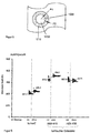
- Figure 9 shows the head part of a metal fixing material bushing according to the invention and Figures 10a to 10b the scheme of the electrochemical reactions in the area of the metal fixing material implementation due to different electrochemical potentials in the prior art and according to the invention.
- Figure 9 shows first the head part of a glass-metal fixing material leadthrough according to the invention, as in FIG Figures 1a and 1b shown. Same components as in the Figures 1a and 1b are given the same reference numbers.
- a conductive film for example a water film 200, can form on the surface of the base body 1, so that if the electrochemical potential of the base body and the metal pin differ, there is an electron flow from the metal pin to the ground, here the base body 1, whereby a Oxidation of the metal pin and / or of the base body and / or even of the fixing material, for example the glass material, can be caused.
- the electron flow from the metal pin to the base body takes place via the bridge wire 9.
- the electrically conductive film 200 can be present in particular in long-term operation of a generic bushing and play a role in the long-term stability of and corrosion attacks on the bushing.
- the electrons flow over the bridge wire 9 from the head of the metal pin 500 to the base body 501 or possibly. in the other direction, depending on the potential difference.
- the insulating material between the base body and the metal pin is usually a non-conductive fixing material, preferably a glass or glass ceramic material.
- the glass or glass ceramic material into which the metallic conductor is glazed is denoted by 10.
- the metal pin guided through the opening has the reference number 5
- the metal pin soldered to the base body with the aid of a solder material 7 has the reference number 6.
- Figure 10a shows the flow of electrons from the metal pin to the base body due to different electrochemical potentials.
- the difference in the electrochemical potential of a metal pin made of a non-stainless steel, in particular NiFe, and the base body in the prior art was more than 0.3 V. Due to this difference in the electrochemical potential, if there is an electrically conductive layer on the metal pin and the Base body, for example in the presence of a water film 200, for a conversion of iron to Fe 2+ and the release of two electrons come, which have migrated to the base body due to the existing electrical connection. With oxygen in the presence of water, 2 OH is formed - as in Figure 10a shown, i.e.
- the water film becomes increasingly basic and the material of the metal pin oxidizes to Fe 2+ .
- Same reference numbers as in Figure 9 are also in Figure 10a assigned identically.
- 500 designates the area of the metal pin
- 501 the area of the base body.
- the electron flow from the metal pin to the base body takes place via the bridging wire 9 or even via the electrically conductive film 200, in particular if this becomes more and more basic as the reaction progresses.
- the increasing basicity of the film 200 can intensify the corrosive attack on the metals and even the glass material.
- the layer 5110 on the base body made of stainless steel is a passivation layer that forms on the stainless steel and can in particular contain oxygen.
- NiFe as the pin material, it was observed that a local cell can form between this passivation layer 5110 and the metal pin made of non-stainless steel, especially those made of NiFe.
- the electrochemical potential difference between NiFe as the pin material and, for example, AISI 304L as the material of the base body is 0.38 V. This can lead to electrochemical corrosion.
- the metal pin can thus corrode in the prior art, this is no longer possible or at least strongly suppressed according to the invention, since the metal pin in area 500 has essentially the same electrochemical potential as the base body with reference number 501. As in Figure 10b As shown, there is then no flow of electrons from the metal pin to the base body, even if the base body and metal pin are provided with an electrically conductive film 200, in particular a film of water.
- the surface 5110 of the base body and in particular the metal pin are passivation layers which form on stainless steel and which can contain oxygen but do not oxidize further. In particular, there is also no water film that becomes increasingly basic.
- the absolute amount of the electrochemical potential difference is 0.02 V.
- electrochemical corrosion attacks are at least very strongly suppressed.
- the absolute value of the difference in the electrochemical potential of the base body and the stainless steel pin in the component according to the invention is preferably only from 0.3 V to 0.0 V, advantageously 0.1 V to 0.0 V, particularly advantageously 0.05 V to 0.0 V.
- Figure 11 shows the position of the electrochemical potentials of a selection of possible materials, in particular stainless steels for the metal pin or pins and / or also for the base body.
- achieving good corrosion resistance depends on an appropriate material combination of base body and metal pin in the fixing material.
- the aim is that the potential difference is as small as possible.
- the material of the base body must also meet other requirements. In particular, it must be able to be welded to the metal cap 2, in particular by laser welding.
- the manufacturing process for the base body is also an aspect, in particular if it is punched out or cold-formed. In the case of cold-formed base bodies, a copper content can be advantageous.
- stainless steel In the selection of the metal pins 5, 6, in particular the metal pin 5 arranged in the fixing material, and also for the selection of the material of the base body, those in FIG Figure 11 Materials listed as stainless steel are particularly advantageous. These are the stainless steel types (AISI) 316, 317, 302, 304, 321, 317, 430, 410 and / or 416. They are all characterized by the fact that they have a low electrochemical potential difference to seawater, in particular an absolute value of less than 0.4 V, advantageously less than 0.36 V, which, as described, is a good measure for assessing the Resistance to galvanic corrosion attacks for the entire implementation.
- AISI stainless steel types
- the invention thus provides for the first time a metal fixing material bushing which is characterized on the one hand by higher mechanical stability, especially when the metal pins are bent and / or higher pull-out forces of the metal pins, and advantageously also by a lower susceptibility to corrosion, especially in adverse conditions of use.
- the improved corrosion resistance contributes to the long-term stability and thus safety of the facilities in which the implementation according to the invention is used. Overall, the efficiency of the production of objects containing the implementation according to the invention and their safety can thus be increased.
Landscapes
- Health & Medical Sciences (AREA)
- Chemical & Material Sciences (AREA)
- Engineering & Computer Science (AREA)
- Life Sciences & Earth Sciences (AREA)
- Inorganic Chemistry (AREA)
- Veterinary Medicine (AREA)
- Animal Behavior & Ethology (AREA)
- General Health & Medical Sciences (AREA)
- Public Health (AREA)
- Epidemiology (AREA)
- Ceramic Engineering (AREA)
- Transplantation (AREA)
- Medicinal Chemistry (AREA)
- Oral & Maxillofacial Surgery (AREA)
- Dermatology (AREA)
- General Engineering & Computer Science (AREA)
- Heart & Thoracic Surgery (AREA)
- Surgery (AREA)
- Vascular Medicine (AREA)
- Chemical Kinetics & Catalysis (AREA)
- General Chemical & Material Sciences (AREA)
- Geochemistry & Mineralogy (AREA)
- Materials Engineering (AREA)
- Organic Chemistry (AREA)
- Mechanical Engineering (AREA)
- Electrochemistry (AREA)
- Fluid Mechanics (AREA)
- Physics & Mathematics (AREA)
- Manufacturing & Machinery (AREA)
- Radiology & Medical Imaging (AREA)
- Nuclear Medicine, Radiotherapy & Molecular Imaging (AREA)
- Biomedical Technology (AREA)
- Glass Compositions (AREA)
- Insertion Pins And Rivets (AREA)
- Joining Of Glass To Other Materials (AREA)
- Materials For Medical Uses (AREA)
- Air Bags (AREA)
- Electrotherapy Devices (AREA)
Applications Claiming Priority (3)
| Application Number | Priority Date | Filing Date | Title |
|---|---|---|---|
| DE102018005733.0A DE102018005733B4 (de) | 2018-07-20 | 2018-07-20 | Glas-Metall-Durchführung |
| EP19742164.7A EP3824243B1 (fr) | 2018-07-20 | 2019-07-15 | Passage en matériau de fixation métallique à faible risque de défaillance |
| PCT/EP2019/068960 WO2020016153A1 (fr) | 2018-07-20 | 2019-07-15 | Passage en matériau de fixation métallique à faible risque de défaillance |
Related Parent Applications (2)
| Application Number | Title | Priority Date | Filing Date |
|---|---|---|---|
| EP19742164.7A Division-Into EP3824243B1 (fr) | 2018-07-20 | 2019-07-15 | Passage en matériau de fixation métallique à faible risque de défaillance |
| EP19742164.7A Division EP3824243B1 (fr) | 2018-07-20 | 2019-07-15 | Passage en matériau de fixation métallique à faible risque de défaillance |
Publications (2)
| Publication Number | Publication Date |
|---|---|
| EP3851786A1 true EP3851786A1 (fr) | 2021-07-21 |
| EP3851786B1 EP3851786B1 (fr) | 2023-08-30 |
Family
ID=66589282
Family Applications (4)
| Application Number | Title | Priority Date | Filing Date |
|---|---|---|---|
| EP19174825.0A Active EP3597267B1 (fr) | 2018-07-20 | 2019-05-16 | Traversée en verre et en métal |
| EP21193032.6A Pending EP3932476A1 (fr) | 2018-07-20 | 2019-05-16 | Traversée verre métal |
| EP21161856.6A Active EP3851786B1 (fr) | 2018-07-20 | 2019-07-15 | Traversée à métal et matériau de fixation avec faible susceptibilité à la rupture |
| EP19742164.7A Active EP3824243B1 (fr) | 2018-07-20 | 2019-07-15 | Passage en matériau de fixation métallique à faible risque de défaillance |
Family Applications Before (2)
| Application Number | Title | Priority Date | Filing Date |
|---|---|---|---|
| EP19174825.0A Active EP3597267B1 (fr) | 2018-07-20 | 2019-05-16 | Traversée en verre et en métal |
| EP21193032.6A Pending EP3932476A1 (fr) | 2018-07-20 | 2019-05-16 | Traversée verre métal |
Family Applications After (1)
| Application Number | Title | Priority Date | Filing Date |
|---|---|---|---|
| EP19742164.7A Active EP3824243B1 (fr) | 2018-07-20 | 2019-07-15 | Passage en matériau de fixation métallique à faible risque de défaillance |
Country Status (8)
| Country | Link |
|---|---|
| US (5) | US11217440B2 (fr) |
| EP (4) | EP3597267B1 (fr) |
| JP (5) | JP7690288B2 (fr) |
| KR (1) | KR102676058B1 (fr) |
| CN (3) | CN112469956A (fr) |
| DE (2) | DE102018005733B4 (fr) |
| MX (1) | MX2021000600A (fr) |
| WO (1) | WO2020016153A1 (fr) |
Families Citing this family (5)
| Publication number | Priority date | Publication date | Assignee | Title |
|---|---|---|---|---|
| DE102016111390A1 (de) * | 2016-06-21 | 2017-12-21 | Schott Ag | Zumindest teilweise kristallisiertes Glas, eine mit diesem Glas hergestellte Verbindung, beispielsweise eine Metall-Glas-Verbindung, insbesondere eine Metall-Glasverbindung bei einem Durchführungselement sowie ein Verfahren zur Herstellung einer solchen Verbindung, insbesondere bei einem Durchführungselement |
| DE102018005733B4 (de) * | 2018-07-20 | 2021-01-14 | Schott Ag | Glas-Metall-Durchführung |
| DE102020107224A1 (de) * | 2020-03-17 | 2021-09-23 | Schott Ag | Elektrische Einrichtung |
| WO2021219373A1 (fr) * | 2020-04-28 | 2021-11-04 | Schott Ag | Allumeur pour des dispositifs de protection de passager et son procédé de production |
| USD1009943S1 (en) * | 2022-03-22 | 2024-01-02 | Schott Ag | Air bag detonator |
Citations (14)
| Publication number | Priority date | Publication date | Assignee | Title |
|---|---|---|---|---|
| US1813906A (en) | 1928-06-25 | 1931-07-14 | Richmond Lewis | Boiler |
| US3274937A (en) | 1963-04-11 | 1966-09-27 | Physical Sciences Corp | Detonation squib |
| EP0248977A1 (fr) * | 1986-02-27 | 1987-12-16 | Dynamit Nobel Aktiengesellschaft | Elément d'amorçage électrique et son procédé de fabrication |
| US5345872A (en) | 1993-05-28 | 1994-09-13 | Nippon Koki Co., Ltd. | Igniter |
| EP1455160A1 (fr) | 2003-03-03 | 2004-09-08 | Schott Glas | Traversée métal-matériau de fixation et procédé de fabrication d'une tête d'initiateur avec traversée métal-matériau de fixation |
| EP1491848A1 (fr) | 2002-03-29 | 2004-12-29 | Toyota Jidosha Kabushiki Kaisha | Detonateur |
| EP1813906A1 (fr) | 2006-01-27 | 2007-08-01 | Schott AG | Traversée métal - matériau de fixation et utilisation de celle-ci ainsi qu'airbag et tensionneur de ceinture avec initiateur |
| DE102006056077A1 (de) | 2006-11-28 | 2008-05-29 | Schott Ag | Zündvorrichtung für eine pyrotechnische Schutzvorrichtung |
| EP2012082A2 (fr) * | 2007-07-06 | 2009-01-07 | Electrovac AG | Socle en métal/matériau de fixation pour dispositifs d'amorçage d'airbags ou dispositifs de protection de personnes analogues, en particulier pour véhicules à moteur et dispositif d'amorçage doté d'un tel socle |
| EP2431703A2 (fr) | 2010-09-17 | 2012-03-21 | Schott Ag | Elément annulaire ou en forme de plaque et son procédé de fabrication |
| DE102010045624A1 (de) | 2010-09-17 | 2012-03-22 | Schott Ag | Ring- oder plattenförmiges Element |
| WO2012110242A1 (fr) | 2011-02-18 | 2012-08-23 | Schott Ag | Passage |
| DE102012010608A1 (de) * | 2012-05-16 | 2013-11-21 | Trw Airbag Systems Gmbh | Anzünder und Verfahren zur Herstellung eines Anzünders für einen Gasgenerator |
| AT513238B1 (de) * | 2012-07-25 | 2014-07-15 | Electrovac Hacht & Huber Gmbh | Verfahren zur Herstellung eines Metallgrundkörpers für einen Zünder für einen Gasgenerator |
Family Cites Families (22)
| Publication number | Priority date | Publication date | Assignee | Title |
|---|---|---|---|---|
| US3669698A (en) * | 1969-12-29 | 1972-06-13 | Gen Electric | Seal glasses |
| US5709724A (en) * | 1994-08-04 | 1998-01-20 | Coors Ceramics Company | Process for fabricating a hermetic glass-to-metal seal |
| JPH1047892A (ja) * | 1996-07-31 | 1998-02-20 | Uchihashi Estec Co Ltd | 電気雷管用点火部品 |
| EP1028923B1 (fr) * | 1997-09-30 | 2004-11-17 | Coors Ceramics Company | Procede de fabrication d'un joint verre-metal hermetique |
| DE19842943C2 (de) * | 1998-09-18 | 2001-09-20 | Schott Glas | Biokompatible Glas-Metall-Durchführungen und ihre Verwendung |
| US7056358B2 (en) * | 2000-04-05 | 2006-06-06 | Wilson Greatbatch Technologies, Inc. | Method for using high rate lithium electrochemical cell containing SVO/CFchi/SVo sandwich cathodes having γ-SVO and mixture of γ-SVO/ε-SVO |
| NO314897B1 (no) * | 2000-08-23 | 2003-06-10 | Norsk Hydro As | Barium-lantan-silikat baserte glasskeramer og deres anvendelse |
| US6877431B2 (en) * | 2002-10-21 | 2005-04-12 | Schott Glas | Hermetically sealed electrical feed-through device with a bent isolated pin in a circular glass seal |
| US7837085B1 (en) * | 2003-04-09 | 2010-11-23 | Boston Scientific Neuromodulation Corporation | Hermetic seal |
| US20050021127A1 (en) * | 2003-07-21 | 2005-01-27 | Kawula Paul John | Porous glass fused onto stent for drug retention |
| JP5090184B2 (ja) | 2006-01-18 | 2012-12-05 | 日本化薬株式会社 | ガスアクチュエータ用小型ガス発生器及びプリテンショナーシステム |
| US9134100B2 (en) * | 2009-04-13 | 2015-09-15 | Ensign-Bickford Aerospace & Defense Company | Surface mountable semiconductor bridge die |
| US20120067100A1 (en) | 2010-09-20 | 2012-03-22 | Ati Properties, Inc. | Elevated Temperature Forming Methods for Metallic Materials |
| EP2909875B1 (fr) * | 2012-10-16 | 2020-06-17 | Ambri Inc. | Dispositifs et boîtiers pour le stockage d'énergie électrochimique |
| ITUB20152903A1 (it) * | 2014-08-14 | 2017-02-05 | Schott Ag | Passaggio elettrico e suo utilizzo |
| DE102014016600A1 (de) * | 2014-11-11 | 2016-05-12 | Schott Ag | Durchführung |
| DE102015115958A1 (de) * | 2015-09-22 | 2017-03-23 | Schott Ag | Medizinisches Glaselement |
| US10541391B2 (en) * | 2015-09-30 | 2020-01-21 | Apple Inc. | Electrical feedthroughs for battery housings |
| EP3284512B1 (fr) * | 2016-08-17 | 2019-11-13 | Heraeus Deutschland GmbH & Co. KG | Passage electrique comprenant une liaison electrique frittee en particulier pour implants medicaux |
| CN108172553A (zh) | 2018-01-17 | 2018-06-15 | 杭州暖芯迦电子科技有限公司 | 一种视网膜假体植入芯片的封装结构及其封装方法 |
| US11264584B2 (en) * | 2018-04-10 | 2022-03-01 | Sharp Kabushiki Kaisha | Display device and method for manufacturing same |
| DE102018005733B4 (de) * | 2018-07-20 | 2021-01-14 | Schott Ag | Glas-Metall-Durchführung |
-
2018
- 2018-07-20 DE DE102018005733.0A patent/DE102018005733B4/de active Active
-
2019
- 2019-05-16 EP EP19174825.0A patent/EP3597267B1/fr active Active
- 2019-05-16 DE DE202019005450.2U patent/DE202019005450U1/de active Active
- 2019-05-16 EP EP21193032.6A patent/EP3932476A1/fr active Pending
- 2019-07-15 JP JP2020570825A patent/JP7690288B2/ja active Active
- 2019-07-15 KR KR1020207035630A patent/KR102676058B1/ko active Active
- 2019-07-15 EP EP21161856.6A patent/EP3851786B1/fr active Active
- 2019-07-15 MX MX2021000600A patent/MX2021000600A/es unknown
- 2019-07-15 EP EP19742164.7A patent/EP3824243B1/fr active Active
- 2019-07-15 WO PCT/EP2019/068960 patent/WO2020016153A1/fr not_active Ceased
- 2019-07-15 CN CN201980048549.9A patent/CN112469956A/zh active Pending
- 2019-07-19 US US16/516,507 patent/US11217440B2/en active Active
- 2019-07-19 JP JP2019133342A patent/JP6861765B2/ja active Active
- 2019-07-22 CN CN202211072632.XA patent/CN115282348B/zh active Active
- 2019-07-22 CN CN201910663264.8A patent/CN110732044B/zh active Active
-
2020
- 2020-10-20 US US17/075,322 patent/US11205569B2/en active Active
-
2021
- 2021-01-20 US US17/153,518 patent/US12125696B2/en active Active
- 2021-03-30 JP JP2021057500A patent/JP7144566B2/ja active Active
- 2021-11-03 US US17/518,054 patent/US11728156B2/en active Active
-
2022
- 2022-09-15 JP JP2022147063A patent/JP7453302B2/ja active Active
-
2024
- 2024-01-12 JP JP2024003600A patent/JP7808396B2/ja active Active
- 2024-07-22 US US18/779,375 patent/US20240379340A1/en active Pending
Patent Citations (21)
| Publication number | Priority date | Publication date | Assignee | Title |
|---|---|---|---|---|
| US1813906A (en) | 1928-06-25 | 1931-07-14 | Richmond Lewis | Boiler |
| US3274937A (en) | 1963-04-11 | 1966-09-27 | Physical Sciences Corp | Detonation squib |
| EP0248977A1 (fr) * | 1986-02-27 | 1987-12-16 | Dynamit Nobel Aktiengesellschaft | Elément d'amorçage électrique et son procédé de fabrication |
| US5345872A (en) | 1993-05-28 | 1994-09-13 | Nippon Koki Co., Ltd. | Igniter |
| EP1491848A1 (fr) | 2002-03-29 | 2004-12-29 | Toyota Jidosha Kabushiki Kaisha | Detonateur |
| EP1455160A1 (fr) | 2003-03-03 | 2004-09-08 | Schott Glas | Traversée métal-matériau de fixation et procédé de fabrication d'une tête d'initiateur avec traversée métal-matériau de fixation |
| US20040216631A1 (en) | 2003-03-03 | 2004-11-04 | Thomas Fink | Metal fixing material bushing and method for producing a base plate of a metal fixing material bushing |
| US20060222881A1 (en) | 2003-03-03 | 2006-10-05 | Schott Ag | Metal fixing material bushing and method for producing a base plate of a metal fixing material bushing |
| US20070187934A1 (en) | 2006-01-27 | 2007-08-16 | Thomas Fink | Metal-sealing material-feedthrough and utilization of the metal-sealing material feedthrough with an airbag, a belt tensioning device, and an ignition device |
| DE102006004036A1 (de) | 2006-01-27 | 2007-08-09 | Schott Ag | Metall-Fixiermaterial-Durchführung und Verwendung einer derartigen Durchführung sowie Airbag und Gurtspanner mit einer Zündeinrichtung |
| EP1813906A1 (fr) | 2006-01-27 | 2007-08-01 | Schott AG | Traversée métal - matériau de fixation et utilisation de celle-ci ainsi qu'airbag et tensionneur de ceinture avec initiateur |
| EP2270417A2 (fr) | 2006-01-27 | 2011-01-05 | Schott Ag | Traversée métal - matériau de fixation et utilisation de celle-ci ainsi qu'airbag et tensionneur de ceinture avec initiateur |
| DE102006056077A1 (de) | 2006-11-28 | 2008-05-29 | Schott Ag | Zündvorrichtung für eine pyrotechnische Schutzvorrichtung |
| EP2012082A2 (fr) * | 2007-07-06 | 2009-01-07 | Electrovac AG | Socle en métal/matériau de fixation pour dispositifs d'amorçage d'airbags ou dispositifs de protection de personnes analogues, en particulier pour véhicules à moteur et dispositif d'amorçage doté d'un tel socle |
| EP2431703A2 (fr) | 2010-09-17 | 2012-03-21 | Schott Ag | Elément annulaire ou en forme de plaque et son procédé de fabrication |
| DE102010045624A1 (de) | 2010-09-17 | 2012-03-22 | Schott Ag | Ring- oder plattenförmiges Element |
| DE202010018430U1 (de) * | 2010-09-17 | 2016-07-21 | Schott Ag | Ring- oder plattenförmiges Element |
| WO2012110242A1 (fr) | 2011-02-18 | 2012-08-23 | Schott Ag | Passage |
| WO2012110245A1 (fr) | 2011-02-18 | 2012-08-23 | Schott Ag | Passage destiné en particulier à des batteries et procédé pour intégrer ce passage dans un boîtier par soudage par ultrasons |
| DE102012010608A1 (de) * | 2012-05-16 | 2013-11-21 | Trw Airbag Systems Gmbh | Anzünder und Verfahren zur Herstellung eines Anzünders für einen Gasgenerator |
| AT513238B1 (de) * | 2012-07-25 | 2014-07-15 | Electrovac Hacht & Huber Gmbh | Verfahren zur Herstellung eines Metallgrundkörpers für einen Zünder für einen Gasgenerator |
Also Published As
Similar Documents
| Publication | Publication Date | Title |
|---|---|---|
| EP3851786B1 (fr) | Traversée à métal et matériau de fixation avec faible susceptibilité à la rupture | |
| EP2431703B1 (fr) | Traversée métal - matériau de fixation et son procédé de fabrication | |
| EP1455160B1 (fr) | Traversée métal-matériau de fixation et procédé de fabrication d'une tête d'initiateur avec traversée métal-matériau de fixation | |
| DE102009008673B3 (de) | Gestanztes Durchführungselement mit eingelötetem Kontaktstift | |
| DE102010011150B4 (de) | Elektrische Sicherung für Kraftfahrzeugenergieleitungen und Herstellungsverfahren für eine solche Sicherung | |
| EP2270417B1 (fr) | Traversée métal - matériau de fixation et utilisation de celle-ci ainsi qu'airbag et tensionneur de ceinture avec initiateur | |
| EP2012082B1 (fr) | Socle en métal/matériau de fixation pour dispositifs d'amorçage d'airbags ou dispositifs de protection de personnes analogues, en particulier pour véhicules à moteur et dispositif d'amorçage doté d'un tel socle | |
| EP3667761B1 (fr) | Cellule cylindrique à languettes de contact | |
| DE102010045641A1 (de) | Verfahren zur Herstellung eines ring- oder plattenförmigen Elementes | |
| WO2012167921A1 (fr) | Passage | |
| EP2251633B1 (fr) | Traversée métal-matériau de fixation et procédé de fabrication d'un corps de base avec une traversée métal-matériau de fixation | |
| DE102018215025A1 (de) | Elektrischer Kontakt zum Zusammenstecken mit einem Gegenkontakt | |
| DE102011103975A1 (de) | Durchführungsbauteil | |
| AT394637B (de) | Lotpille | |
| DE102010045624C5 (de) | Ring- oder plattenförmiges Element | |
| EP3997412B1 (fr) | Détonateur pyrotechnique et procédé de fabrication d'un détonateur pyrotechnique | |
| DE102018100020B4 (de) | Verfahren und Vorrichtung zur Herstellung einer Verbindung zwischen einem Crimpkontakt und einem Litzenleiter | |
| DE102012221466B4 (de) | Bauteilverbund zwischen zwei der Stromführung dienenden Bauteilen und Verfahren zur Herstellung eines Bauteileverbunds | |
| EP3904822A1 (fr) | Système d'allumage de dispositifs de protection des personnes et son procédé de fabrication | |
| DE202020102354U1 (de) | Anzünder von Personenschutzeinrichtungen | |
| WO2020083775A1 (fr) | Broche de raccordement pour traversées et son procédé de fabrication | |
| EP4143497A1 (fr) | Allumeur pour des dispositifs de protection de passager et son procédé de production | |
| EP3783740A1 (fr) | Raccordement d'un contact à sertir à un conducteur ainsi que procédé de fabrication d'un contact à sertir | |
| DE102014219125A1 (de) | Durchführungselement mit direkt verbundenem Massestift, Verfahren zu seiner Herstellung und seine Verwendung |
Legal Events
| Date | Code | Title | Description |
|---|---|---|---|
| PUAI | Public reference made under article 153(3) epc to a published international application that has entered the european phase |
Free format text: ORIGINAL CODE: 0009012 |
|
| STAA | Information on the status of an ep patent application or granted ep patent |
Free format text: STATUS: THE APPLICATION HAS BEEN PUBLISHED |
|
| AC | Divisional application: reference to earlier application |
Ref document number: 3824243 Country of ref document: EP Kind code of ref document: P |
|
| AK | Designated contracting states |
Kind code of ref document: A1 Designated state(s): AL AT BE BG CH CY CZ DE DK EE ES FI FR GB GR HR HU IE IS IT LI LT LU LV MC MK MT NL NO PL PT RO RS SE SI SK SM TR |
|
| STAA | Information on the status of an ep patent application or granted ep patent |
Free format text: STATUS: REQUEST FOR EXAMINATION WAS MADE |
|
| 17P | Request for examination filed |
Effective date: 20210825 |
|
| RBV | Designated contracting states (corrected) |
Designated state(s): AL AT BE BG CH CY CZ DE DK EE ES FI FR GB GR HR HU IE IS IT LI LT LU LV MC MK MT NL NO PL PT RO RS SE SI SK SM TR |
|
| RAP3 | Party data changed (applicant data changed or rights of an application transferred) |
Owner name: SCHOTT AG |
|
| GRAP | Despatch of communication of intention to grant a patent |
Free format text: ORIGINAL CODE: EPIDOSNIGR1 |
|
| STAA | Information on the status of an ep patent application or granted ep patent |
Free format text: STATUS: GRANT OF PATENT IS INTENDED |
|
| RIC1 | Information provided on ipc code assigned before grant |
Ipc: F42B 3/198 20060101ALN20230315BHEP Ipc: F42B 3/107 20060101ALN20230315BHEP Ipc: A61N 1/375 20060101ALI20230315BHEP Ipc: F42B 3/11 20060101AFI20230315BHEP |
|
| INTG | Intention to grant announced |
Effective date: 20230329 |
|
| P01 | Opt-out of the competence of the unified patent court (upc) registered |
Effective date: 20230516 |
|
| GRAS | Grant fee paid |
Free format text: ORIGINAL CODE: EPIDOSNIGR3 |
|
| GRAA | (expected) grant |
Free format text: ORIGINAL CODE: 0009210 |
|
| STAA | Information on the status of an ep patent application or granted ep patent |
Free format text: STATUS: THE PATENT HAS BEEN GRANTED |
|
| AC | Divisional application: reference to earlier application |
Ref document number: 3824243 Country of ref document: EP Kind code of ref document: P |
|
| AK | Designated contracting states |
Kind code of ref document: B1 Designated state(s): AL AT BE BG CH CY CZ DE DK EE ES FI FR GB GR HR HU IE IS IT LI LT LU LV MC MK MT NL NO PL PT RO RS SE SI SK SM TR |
|
| REG | Reference to a national code |
Ref country code: GB Ref legal event code: FG4D Free format text: NOT ENGLISH |
|
| REG | Reference to a national code |
Ref country code: CH Ref legal event code: EP |
|
| REG | Reference to a national code |
Ref country code: DE Ref legal event code: R096 Ref document number: 502019009202 Country of ref document: DE |
|
| REG | Reference to a national code |
Ref country code: IE Ref legal event code: FG4D Free format text: LANGUAGE OF EP DOCUMENT: GERMAN |
|
| REG | Reference to a national code |
Ref country code: LT Ref legal event code: MG9D |
|
| REG | Reference to a national code |
Ref country code: NL Ref legal event code: MP Effective date: 20230830 |
|
| PG25 | Lapsed in a contracting state [announced via postgrant information from national office to epo] |
Ref country code: GR Free format text: LAPSE BECAUSE OF FAILURE TO SUBMIT A TRANSLATION OF THE DESCRIPTION OR TO PAY THE FEE WITHIN THE PRESCRIBED TIME-LIMIT Effective date: 20231201 |
|
| PG25 | Lapsed in a contracting state [announced via postgrant information from national office to epo] |
Ref country code: IS Free format text: LAPSE BECAUSE OF FAILURE TO SUBMIT A TRANSLATION OF THE DESCRIPTION OR TO PAY THE FEE WITHIN THE PRESCRIBED TIME-LIMIT Effective date: 20231230 |
|
| PG25 | Lapsed in a contracting state [announced via postgrant information from national office to epo] |
Ref country code: SE Free format text: LAPSE BECAUSE OF FAILURE TO SUBMIT A TRANSLATION OF THE DESCRIPTION OR TO PAY THE FEE WITHIN THE PRESCRIBED TIME-LIMIT Effective date: 20230830 Ref country code: RS Free format text: LAPSE BECAUSE OF FAILURE TO SUBMIT A TRANSLATION OF THE DESCRIPTION OR TO PAY THE FEE WITHIN THE PRESCRIBED TIME-LIMIT Effective date: 20230830 Ref country code: NO Free format text: LAPSE BECAUSE OF FAILURE TO SUBMIT A TRANSLATION OF THE DESCRIPTION OR TO PAY THE FEE WITHIN THE PRESCRIBED TIME-LIMIT Effective date: 20231130 Ref country code: LV Free format text: LAPSE BECAUSE OF FAILURE TO SUBMIT A TRANSLATION OF THE DESCRIPTION OR TO PAY THE FEE WITHIN THE PRESCRIBED TIME-LIMIT Effective date: 20230830 Ref country code: LT Free format text: LAPSE BECAUSE OF FAILURE TO SUBMIT A TRANSLATION OF THE DESCRIPTION OR TO PAY THE FEE WITHIN THE PRESCRIBED TIME-LIMIT Effective date: 20230830 Ref country code: IS Free format text: LAPSE BECAUSE OF FAILURE TO SUBMIT A TRANSLATION OF THE DESCRIPTION OR TO PAY THE FEE WITHIN THE PRESCRIBED TIME-LIMIT Effective date: 20231230 Ref country code: HR Free format text: LAPSE BECAUSE OF FAILURE TO SUBMIT A TRANSLATION OF THE DESCRIPTION OR TO PAY THE FEE WITHIN THE PRESCRIBED TIME-LIMIT Effective date: 20230830 Ref country code: GR Free format text: LAPSE BECAUSE OF FAILURE TO SUBMIT A TRANSLATION OF THE DESCRIPTION OR TO PAY THE FEE WITHIN THE PRESCRIBED TIME-LIMIT Effective date: 20231201 Ref country code: FI Free format text: LAPSE BECAUSE OF FAILURE TO SUBMIT A TRANSLATION OF THE DESCRIPTION OR TO PAY THE FEE WITHIN THE PRESCRIBED TIME-LIMIT Effective date: 20230830 |
|
| PG25 | Lapsed in a contracting state [announced via postgrant information from national office to epo] |
Ref country code: PL Free format text: LAPSE BECAUSE OF FAILURE TO SUBMIT A TRANSLATION OF THE DESCRIPTION OR TO PAY THE FEE WITHIN THE PRESCRIBED TIME-LIMIT Effective date: 20230830 Ref country code: NL Free format text: LAPSE BECAUSE OF FAILURE TO SUBMIT A TRANSLATION OF THE DESCRIPTION OR TO PAY THE FEE WITHIN THE PRESCRIBED TIME-LIMIT Effective date: 20230830 |
|
| PG25 | Lapsed in a contracting state [announced via postgrant information from national office to epo] |
Ref country code: ES Free format text: LAPSE BECAUSE OF FAILURE TO SUBMIT A TRANSLATION OF THE DESCRIPTION OR TO PAY THE FEE WITHIN THE PRESCRIBED TIME-LIMIT Effective date: 20230830 |
|
| PG25 | Lapsed in a contracting state [announced via postgrant information from national office to epo] |
Ref country code: SM Free format text: LAPSE BECAUSE OF FAILURE TO SUBMIT A TRANSLATION OF THE DESCRIPTION OR TO PAY THE FEE WITHIN THE PRESCRIBED TIME-LIMIT Effective date: 20230830 Ref country code: RO Free format text: LAPSE BECAUSE OF FAILURE TO SUBMIT A TRANSLATION OF THE DESCRIPTION OR TO PAY THE FEE WITHIN THE PRESCRIBED TIME-LIMIT Effective date: 20230830 Ref country code: ES Free format text: LAPSE BECAUSE OF FAILURE TO SUBMIT A TRANSLATION OF THE DESCRIPTION OR TO PAY THE FEE WITHIN THE PRESCRIBED TIME-LIMIT Effective date: 20230830 Ref country code: EE Free format text: LAPSE BECAUSE OF FAILURE TO SUBMIT A TRANSLATION OF THE DESCRIPTION OR TO PAY THE FEE WITHIN THE PRESCRIBED TIME-LIMIT Effective date: 20230830 Ref country code: DK Free format text: LAPSE BECAUSE OF FAILURE TO SUBMIT A TRANSLATION OF THE DESCRIPTION OR TO PAY THE FEE WITHIN THE PRESCRIBED TIME-LIMIT Effective date: 20230830 Ref country code: CZ Free format text: LAPSE BECAUSE OF FAILURE TO SUBMIT A TRANSLATION OF THE DESCRIPTION OR TO PAY THE FEE WITHIN THE PRESCRIBED TIME-LIMIT Effective date: 20230830 Ref country code: PT Free format text: LAPSE BECAUSE OF FAILURE TO SUBMIT A TRANSLATION OF THE DESCRIPTION OR TO PAY THE FEE WITHIN THE PRESCRIBED TIME-LIMIT Effective date: 20240102 Ref country code: SK Free format text: LAPSE BECAUSE OF FAILURE TO SUBMIT A TRANSLATION OF THE DESCRIPTION OR TO PAY THE FEE WITHIN THE PRESCRIBED TIME-LIMIT Effective date: 20230830 |
|
| PG25 | Lapsed in a contracting state [announced via postgrant information from national office to epo] |
Ref country code: IT Free format text: LAPSE BECAUSE OF FAILURE TO SUBMIT A TRANSLATION OF THE DESCRIPTION OR TO PAY THE FEE WITHIN THE PRESCRIBED TIME-LIMIT Effective date: 20230830 |
|
| REG | Reference to a national code |
Ref country code: DE Ref legal event code: R097 Ref document number: 502019009202 Country of ref document: DE |
|
| PLBE | No opposition filed within time limit |
Free format text: ORIGINAL CODE: 0009261 |
|
| STAA | Information on the status of an ep patent application or granted ep patent |
Free format text: STATUS: NO OPPOSITION FILED WITHIN TIME LIMIT |
|
| PG25 | Lapsed in a contracting state [announced via postgrant information from national office to epo] |
Ref country code: SI Free format text: LAPSE BECAUSE OF FAILURE TO SUBMIT A TRANSLATION OF THE DESCRIPTION OR TO PAY THE FEE WITHIN THE PRESCRIBED TIME-LIMIT Effective date: 20230830 |
|
| 26N | No opposition filed |
Effective date: 20240603 |
|
| PG25 | Lapsed in a contracting state [announced via postgrant information from national office to epo] |
Ref country code: BG Free format text: LAPSE BECAUSE OF FAILURE TO SUBMIT A TRANSLATION OF THE DESCRIPTION OR TO PAY THE FEE WITHIN THE PRESCRIBED TIME-LIMIT Effective date: 20230830 |
|
| PG25 | Lapsed in a contracting state [announced via postgrant information from national office to epo] |
Ref country code: BG Free format text: LAPSE BECAUSE OF FAILURE TO SUBMIT A TRANSLATION OF THE DESCRIPTION OR TO PAY THE FEE WITHIN THE PRESCRIBED TIME-LIMIT Effective date: 20230830 |
|
| PG25 | Lapsed in a contracting state [announced via postgrant information from national office to epo] |
Ref country code: MC Free format text: LAPSE BECAUSE OF FAILURE TO SUBMIT A TRANSLATION OF THE DESCRIPTION OR TO PAY THE FEE WITHIN THE PRESCRIBED TIME-LIMIT Effective date: 20230830 |
|
| REG | Reference to a national code |
Ref country code: CH Ref legal event code: PL |
|
| PG25 | Lapsed in a contracting state [announced via postgrant information from national office to epo] |
Ref country code: LU Free format text: LAPSE BECAUSE OF NON-PAYMENT OF DUE FEES Effective date: 20240715 |
|
| GBPC | Gb: european patent ceased through non-payment of renewal fee |
Effective date: 20240715 |
|
| PG25 | Lapsed in a contracting state [announced via postgrant information from national office to epo] |
Ref country code: LU Free format text: LAPSE BECAUSE OF NON-PAYMENT OF DUE FEES Effective date: 20240715 |
|
| PG25 | Lapsed in a contracting state [announced via postgrant information from national office to epo] |
Ref country code: BE Free format text: LAPSE BECAUSE OF NON-PAYMENT OF DUE FEES Effective date: 20240731 Ref country code: CH Free format text: LAPSE BECAUSE OF NON-PAYMENT OF DUE FEES Effective date: 20240731 |
|
| PG25 | Lapsed in a contracting state [announced via postgrant information from national office to epo] |
Ref country code: GB Free format text: LAPSE BECAUSE OF NON-PAYMENT OF DUE FEES Effective date: 20240715 |
|
| REG | Reference to a national code |
Ref country code: BE Ref legal event code: MM Effective date: 20240731 |
|
| PG25 | Lapsed in a contracting state [announced via postgrant information from national office to epo] |
Ref country code: IE Free format text: LAPSE BECAUSE OF NON-PAYMENT OF DUE FEES Effective date: 20240715 |
|
| REG | Reference to a national code |
Ref country code: AT Ref legal event code: MM01 Ref document number: 1605958 Country of ref document: AT Kind code of ref document: T Effective date: 20240715 |
|
| PGFP | Annual fee paid to national office [announced via postgrant information from national office to epo] |
Ref country code: DE Payment date: 20250722 Year of fee payment: 7 |
|
| PG25 | Lapsed in a contracting state [announced via postgrant information from national office to epo] |
Ref country code: AT Free format text: LAPSE BECAUSE OF NON-PAYMENT OF DUE FEES Effective date: 20240715 |
|
| PGFP | Annual fee paid to national office [announced via postgrant information from national office to epo] |
Ref country code: FR Payment date: 20250725 Year of fee payment: 7 |
|
| PG25 | Lapsed in a contracting state [announced via postgrant information from national office to epo] |
Ref country code: CY Free format text: LAPSE BECAUSE OF FAILURE TO SUBMIT A TRANSLATION OF THE DESCRIPTION OR TO PAY THE FEE WITHIN THE PRESCRIBED TIME-LIMIT; INVALID AB INITIO Effective date: 20190715 |
|
| PG25 | Lapsed in a contracting state [announced via postgrant information from national office to epo] |
Ref country code: HU Free format text: LAPSE BECAUSE OF FAILURE TO SUBMIT A TRANSLATION OF THE DESCRIPTION OR TO PAY THE FEE WITHIN THE PRESCRIBED TIME-LIMIT; INVALID AB INITIO Effective date: 20190715 |