EP3852274A1 - Procédé et dispositif de codage de code polaire pour concaténer un code crc - Google Patents
Procédé et dispositif de codage de code polaire pour concaténer un code crc Download PDFInfo
- Publication number
- EP3852274A1 EP3852274A1 EP19910624.6A EP19910624A EP3852274A1 EP 3852274 A1 EP3852274 A1 EP 3852274A1 EP 19910624 A EP19910624 A EP 19910624A EP 3852274 A1 EP3852274 A1 EP 3852274A1
- Authority
- EP
- European Patent Office
- Prior art keywords
- bits
- matrix
- rows
- reliability
- encoding
- Prior art date
- Legal status (The legal status is an assumption and is not a legal conclusion. Google has not performed a legal analysis and makes no representation as to the accuracy of the status listed.)
- Granted
Links
Images






Classifications
-
- H—ELECTRICITY
- H03—ELECTRONIC CIRCUITRY
- H03M—CODING; DECODING; CODE CONVERSION IN GENERAL
- H03M13/00—Coding, decoding or code conversion, for error detection or error correction; Coding theory basic assumptions; Coding bounds; Error probability evaluation methods; Channel models; Simulation or testing of codes
- H03M13/29—Coding, decoding or code conversion, for error detection or error correction; Coding theory basic assumptions; Coding bounds; Error probability evaluation methods; Channel models; Simulation or testing of codes combining two or more codes or code structures, e.g. product codes, generalised product codes, concatenated codes, inner and outer codes
- H03M13/2906—Coding, decoding or code conversion, for error detection or error correction; Coding theory basic assumptions; Coding bounds; Error probability evaluation methods; Channel models; Simulation or testing of codes combining two or more codes or code structures, e.g. product codes, generalised product codes, concatenated codes, inner and outer codes using block codes
-
- H—ELECTRICITY
- H03—ELECTRONIC CIRCUITRY
- H03M—CODING; DECODING; CODE CONVERSION IN GENERAL
- H03M13/00—Coding, decoding or code conversion, for error detection or error correction; Coding theory basic assumptions; Coding bounds; Error probability evaluation methods; Channel models; Simulation or testing of codes
- H03M13/03—Error detection or forward error correction by redundancy in data representation, i.e. code words containing more digits than the source words
- H03M13/05—Error detection or forward error correction by redundancy in data representation, i.e. code words containing more digits than the source words using block codes, i.e. a predetermined number of check bits joined to a predetermined number of information bits
- H03M13/09—Error detection only, e.g. using cyclic redundancy check [CRC] codes or single parity bit
-
- H—ELECTRICITY
- H03—ELECTRONIC CIRCUITRY
- H03M—CODING; DECODING; CODE CONVERSION IN GENERAL
- H03M13/00—Coding, decoding or code conversion, for error detection or error correction; Coding theory basic assumptions; Coding bounds; Error probability evaluation methods; Channel models; Simulation or testing of codes
- H03M13/03—Error detection or forward error correction by redundancy in data representation, i.e. code words containing more digits than the source words
- H03M13/05—Error detection or forward error correction by redundancy in data representation, i.e. code words containing more digits than the source words using block codes, i.e. a predetermined number of check bits joined to a predetermined number of information bits
- H03M13/13—Linear codes
Definitions
- This application relates to the field of communications technologies, and more specifically, to a method and an apparatus for encoding a polar code concatenated with a CRC code.
- channel encoding plays a critical role in ensuring reliable data transmission.
- channel encoding is usually performed by using a turbo code, a low density parity check (low density parity check, LDPC) code, and a polar (Polar) code.
- the polar code (which is also referred to as a polarization code) is an encoding scheme that is proposed by Professor Arikan based on channel polarization.
- the polar code is the first and the only well-proved channel encoding method currently that can "reach" a channel capacity. In a case of different code lengths, particularly for a finite code, performance of the polar code is far better than that of the turbo code and the LDPC code.
- the polar code has relatively low computational complexity in terms of encoding and decoding. These advantages enable the polar code to have great development and application prospects in the communications field. However, with rapid evolution of a wireless communications system, these communication scenarios have a higher requirement on the performance of the polar code.
- This application provides a method and an apparatus for encoding a polar code concatenated with a CRC code, and performance of a polar code concatenated with a CRC code in this method is better than that of a polar code in a conventional concatenation solution.
- an encoding method includes:
- an encoding apparatus includes:
- a decoding method includes:
- a decoding apparatus includes:
- the M bits are determined based on the row weights of the K rows, in the first matrix, corresponding to the K polarized subchannels on which the K bits are placed, and the M bits are bits corresponding to M rows with relatively small row weights in the K rows or in (K+L) rows.
- the first matrix is an encoding matrix of a polar code.
- a small row weight of the encoding matrix indicates low reliability of a polarized subchannel, and it is very convenient to determine the reliability of the polarized subchannel by using the row weight of the encoding matrix.
- the row weights of the M rows corresponding to the M bits are less than or equal to a first threshold.
- the first threshold is greater than or equal to a minimum value in the row weights of the K rows corresponding to the K bits.
- the first threshold is determined based on a minimum code distance of the polar code.
- the M bits are determined based on the reliability of the K polarized subchannels on which the K bits are placed.
- the M bits are M bits corresponding to M polarized subchannels with relatively low reliability in the K polarized subchannels on which the K bits are placed.
- CRC encoding is performed on bits with low channel reliability, and bits with high channel reliability are directly mapped to polarized subchannels. Compared with a conventional concatenation solution with a same CRC code length, this reduces a frame error rate.
- the M bits are determined based on the reliability of the K polarized subchannels on which the K bits are placed and the row weights of the K rows, in the first matrix, corresponding to the K polarized subchannels on which the K bits are placed.
- the step of determining the M bits includes:
- the M bits are determined based on the reliability of the K polarized subchannels on which the K bits are placed and the row weights of the K rows, in the first matrix, corresponding to the K polarized subchannels on which the K bits are placed.
- the step of determining the M bits includes:
- the M bits corresponding to the M polarized subchannels with the relatively low reliability are determined according to a table or a sequence that represents reliability, or a reliability order of M1 polarized subchannels of the M1 bits is determined according to a table or a sequence that represents reliability.
- the M bits corresponding to the M polarized subchannels with the relatively low reliability are determined based on a capacity (I(W)), or a reliability order of M1 polarized subchannels of the M1 bits is determined based on a capacity (I(W)).
- the M bits corresponding to the M polarized subchannels with the relatively low reliability are determined based on a Bhattacharyya parameter (Z(W)), or a reliability order of M1 polarized subchannels of the M1 bits is determined based on a Bhattacharyya parameter (Z(W)).
- the M bits corresponding to the M polarized subchannels with the relatively low reliability are determined based on an error probability (P(W)), or a reliability order of M1 polarized subchannels of the M1 bits is determined based on an error probability (P(W)).
- an encoding apparatus includes: a processor, configured to execute a program stored in a memory, where when the program is executed, the apparatus is enabled to perform the method in the first aspect or all implementations of the first aspect.
- the memory is located in the apparatus.
- the memory is integrated with the processor.
- the memory is located outside the apparatus.
- the apparatus is a base station or a terminal.
- the apparatus is a chip or an integrated circuit.
- this application provides a computer-readable storage medium.
- the computer-readable storage medium stores a computer program instruction.
- the instruction When the instruction is run on a computer, the computer is enabled to perform the method in any one of the first aspect or the possible implementations of the first aspect, or the second aspect or the possible implementations of the second aspect.
- this application provides a computer program product.
- the computer program product includes computer program code.
- the computer program code When the computer program code is run on a computer, the computer is enabled to perform the method in any one of the first aspect or the possible implementations of the first aspect, or the second aspect or the possible implementations of the second aspect.
- a polar encoding apparatus has functions of implementing the method in any one of the first aspect or the possible designs of the first aspect.
- the functions may be implemented by hardware, or may be implemented by hardware executing corresponding software.
- the hardware or the software includes one or more modules corresponding to the functions.
- the polar encoding apparatus includes a processor, configured to perform the method in any one of the first aspect or the possible designs of the first aspect.
- the polar encoding apparatus further includes a storage unit, configured to store data generated or used in a process in which the processor performs the method in any one of the first aspect or the possible designs of the first aspect.
- the storage unit may be located outside the encoding apparatus, or may be a physically independent unit, or may be storage space or a network hard disk on a cloud server.
- the polar encoding apparatus may be a chip or an integrated circuit.
- the polar encoding apparatus when some or all of the functions are implemented by hardware, includes an input interface, configured to obtain a bit sequence; an encoding circuit, configured to perform a step other than obtaining and output steps in the method in any one of the first aspect or the possible designs of the first aspect; and an output interface, configured to output an encoded codeword.
- the polar encoding apparatus may be a chip or an integrated circuit.
- a communications system includes a network device and a terminal, and the network device or the terminal may perform the method in any one of the first aspect or the possible designs of the first aspect.
- a wireless device includes a polar encoding apparatus and a transceiver that are configured to implement any one of the first aspect or the possible designs of the first aspect.
- the modulator is configured to modulate a processed encoded codeword to obtain a modulated codeword.
- the transceiver is configured to send the modulated codeword.
- the wireless device is a terminal or a network device.
- a polar decoding apparatus has functions of implementing the method in any one of the third aspect or the possible designs of the third aspect.
- the functions may be implemented by hardware, or may be implemented by hardware executing corresponding software.
- the hardware or the software includes one or more modules corresponding to the functions.
- the polar decoding apparatus includes a processor, configured to perform the method in any one of the third aspect or the possible designs of the third aspect.
- the polar decoding apparatus further includes a storage unit, configured to store data generated or used in a process in which the processor performs the method in any one of the first aspect or the possible designs of the first aspect.
- the storage unit may be located outside the encoding apparatus, or may be a physically independent unit, or may be storage space or a network hard disk on a cloud server.
- the polar decoding apparatus may be a chip or an integrated circuit.
- the polar code encoding apparatus when some or all of the functions are implemented by hardware, includes: an input interface, configured to obtain to-be-decoded bits of a bit sequence whose length is K; a decoding circuit, configured to perform a step other than obtaining and output steps in the method in any one of the first aspect or the possible designs of the first aspect; and an output interface, configured to output a bit sequence in a decoding result.
- the polar decoding apparatus may be a chip or an integrated circuit.
- a communications system includes a network device and a terminal, and the network device or the terminal may perform the method in any one of the third aspect or the possible designs of the third aspect.
- a wireless device includes a polar decoding apparatus, a demodulator, and a transceiver that are configured to implement any one of the third aspect or the possible designs of the third aspect.
- the transceiver receives a modulated codeword.
- the demodulator is configured to demodulate the modulated codeword to obtain to-be-decoded information.
- the wireless device is a terminal or a network device.
- the bit sequence for the CRC encoding is selected from a perspective such as the row weights of the encoding matrix (the first matrix), the reliability of the polarized subchannels, comprehensive consideration of the row weights and the reliability, or the like.
- the method for encoding a polar code concatenated with a CRC check code can be used to obtain better performance.
- a network architecture and a service scenario described in embodiments of this application are intended to describe the technical solutions in the embodiments of this application more clearly, and do not constitute a limitation on the technical solutions provided in the embodiments of this application.
- a person of ordinary skill in the art may know that with the evolution of the network architecture and the emergence of a new service scenario, the technical solutions provided in the embodiments of this application are also applicable to a similar technical problem.
- the embodiments of this application can be applied to a wireless communications system.
- the wireless communications system mentioned in the embodiments of this application includes but is not limited to a long term evolution (Long Term Evolution, LTE) system and three application scenarios of a next-generation 5G mobile communications system: enhanced mobile broadband (Enhanced Mobile Broad Band, eMBB), URLLC, and massive machine-type communications (Massive Machine-Type Communications, mMTC).
- the wireless communications system may further be a device-to-device (Device to Device, D2D) communications system, another communications system, a future communications system, or the like.
- a communications apparatus mentioned in this application may be configured in a communications device, and the communications device mainly includes a network device or a terminal device. If a transmit end in this application is a network device, a receive end may be a terminal device. If a transmit end in this application is a terminal device, a receive end may be a network device.
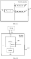
- the wireless communications system in the embodiments of this application is shown in FIG. 1(a) .
- the wireless communications system 100 includes a network device 110 and a terminal 112.
- the network device 110 may be further connected to the core network.
- the network device 101 may further communicate with an IP network 200 such as the Internet (internet), a private IP network, or another data network.
- IP network 200 such as the Internet (internet), a private IP network, or another data network.
- the network device provides a service for a terminal within coverage of the network device.
- the network device 110 provides wireless access for one or more terminals within coverage of the network device 110.
- there may be an overlapping area between coverage of network devices for example, the network device 110 and a network device 120.
- the network devices may further communicate with each other.
- the network device 110 may communicate with the network device 120.
- the communications system 100 is simplified to a system that includes a transmit end 101 and a receive end 102 and that is shown in FIG. 1(b) .
- the transmit end 101 may be the network device 110, and the receive end 102 is the terminal 112; or the transmit end 101 is the terminal 112, and the receive end 102 is the network device 110.
- the network device 110 may be a device configured to communicate with a terminal device.
- the network device 110 may be an evolved NodeB (Evolved NodeB, eNB or eNodeB) in an LTE system, a network side device in a 5G network, a network side device communicating with a terminal in another network, or a network side device in a future network.
- the network device may be a relay station, an access point, a vehicle-mounted device, or the like.
- the network device in a terminal-to-terminal (Device to Device, D2D) communications system, the network device may be a terminal that functions as a base station.
- the network device may include a BBU (Baseband Unit, baseband unit) and an RRU (Remote Radio Unit, remote radio unit).
- BBU Baseband Unit
- RRU Remote Radio Unit
- the BBU and the RRU may be placed at different positions.
- the RRU may be remotely placed in a heavy-traffic area, and the BBU is placed in a central equipment room.
- the BBU and the RRU may alternatively be placed in a same equipment room.
- the BBU and the RRU may alternatively be different components on one rack.
- the terminal may include a handheld device, a vehicle-mounted device, a wearable device, a computing device that has a wireless communication function, another processing device connected to a wireless modem, user equipment (user equipment, UE) in various forms, a mobile station (mobile station, MS), or the like.
- UE user equipment
- MS mobile station
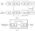
- FIG. 2 is a schematic flowchart of wireless communication.
- a signal source is sent after source encoding, channel encoding, rate matching (optional step), and modulation are sequentially performed.
- the signal source is output to an information destination after demodulation, de-rate matching (optional step), channel decoding, and signal source decoding are sequentially performed.
- the embodiments of this application relate to channel encoding.
- a method for encoding a polar code concatenated with a CRC code described in the embodiments of this application may be used for a channel encoding module.
- the method and the apparatus that are provided in this application are applicable to both a control channel and a data channel.
- a polar code (polar code, also referred to as a polarization code) is an encoding scheme that may theoretically achieve a Shannon capacity limit and has low encoding and decoding complexity, and may be used for channel encoding.
- the polar code is a linear block code. When a code length of the polar code tends to be infinite on a binary discrete memoryless channel (BDMC), the polar code can approach a theoretical channel capacity by using a successive cancellation (SC) decoding method.
- BDMC binary discrete memoryless channel
- SC successive cancellation
- x 1 N is a binary row vector whose length is N, and may also be referred to as an encoded sequence, an output sequence, or a codeword.
- a codeword or sequence whose length is N and that is obtained through polar encoding is also referred to as a mother code, and N may also be referred to as a mother code length or a code length of the mother code.
- F 2 ⁇ log 2 N is defined as a Kronecker (Kronecker) product of log 2 N matrices F 2 .
- G N B N F 2 ⁇ log 2 N , that is, F 2 ⁇ log 2 N is multiplied by a transposed matrix B N , for example, a bit reversal (Bit Reversal) matrix.
- a part of bits in x 1 N are used to carry information, and are referred to as an information bit set or an information bit sequence.
- a set of indexes of these bits may be referred to as an information bit index set or an information bit position set, and is denoted as A.
- the other part of bits are set to fixed values pre-agreed on by the receive end and the transmit end, and these bits are referred to as frozen bits (frozen bits) or a frozen bit set (frozen bit set).
- a set of indexes corresponding to these frozen bits may be referred to as a frozen bit index set or a frozen bit position set, and is represented by using a complementary set A c of A.
- the frozen bits are also referred to as fixed bits, and indicate that these positions are used to place fixed bits, and are not used to place information.
- GN(A) is a sub-matrix obtained from rows corresponding to the indexes in the set A in GN
- GN(AC) is a sub-matrix obtained from rows corresponding to the indexes in the set A c in GN
- u A is an information bit set in x 1 N
- a quantity of information bits is K.
- check bits including but not limited to a cyclic redundancy check (Cyclic Redundancy Check, CRC for short) bit and a parity check (Parity Check, PC for short) bit are also included in the information bit set.
- u A is the information bit set in u 1 N
- u A is a row vector whose length is K, that is,
- K .
- G N (A) is the sub-matrix obtained from the rows corresponding to the indexes in the set A in the matrix G N , and G N (A) is a K ⁇ N matrix.
- a cyclic redundancy check (Cyclic Redundancy Check, CRC for short) code is a most common outer code concatenated with the polar code.
- CRC Cyclic Redundancy Check
- FIG. 3 A block diagram of a conventional procedure in which a polar code concatenated with a CRC code is encoded is shown in FIG. 3 .
- CRC encoding is performed on all to-be-encoded bit sequences based on a given CRC polynomial.
- generated CRC check bits are spliced at an end of the original bit sequence.
- Polar encoding is performed on the CRC check bits obtained after the CRC encoding and the bit sequence.
- bit sequence in this application document is different from the foregoing information bit set or information bit sequence.
- the bit sequence in this application document includes a payload bit (payload) bit.
- payload bit payload bit
- information bits also include the PC bit.
- Solutions of this application provide a method and an apparatus for encoding a polar code concatenated with a CRC code.
- CRC encoding is performed on a part of input bits, and the part of bits are selected according to a specific rule.
- the rule is considered from three possible perspectives: row weights, reliability, or both row weights and reliability, or another possible perspective.
- Polar encoding is performed on a CRC code obtained after the CRC encoding and the input bits, so that performance of a polar code obtained after concatenation is improved.
- a simulation experiment proves that, on an additive white Gaussian noise (AWGN, Additive White Gaussian Noise) channel, a polar code concatenated with a CRC code in the solutions of this application has better performance than that in a conventional concatenation solution.
- AWGN additive white Gaussian noise
- performance is improved by 0.4 db.
- a better effect is obtained when a polar code is concatenated with CRC and a length of the CRC is relatively short.
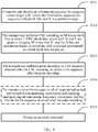
- FIG. 4(a) is a basic flowchart of a method for encoding a polar code concatenated with a CRC code according to an embodiment of this application.
- a part of bits are selected from a to-be-encoded bit sequence according to a specific rule to participate in CRC encoding, to generate CRC check bits.
- the part of bits and the CRC check bits are mapped to polarized subchannels, and remaining bits in the bit sequence are directly mapped to polarized subchannels.
- Polar encoding is performed on all the bits in the bit sequence and the generated CRC check bits, to generate an encoded codeword.
- the method is applied to a sending device. As shown in FIG. 4(a) , the method includes the following steps.
- S101 Obtain a bit sequence whose length is K, where the bit sequence includes K bits, and K is a positive integer.
- S102 Perform cyclic redundancy check CRC encoding on M bits in the K bits to obtain L CRC check bits, where both M and L are positive integers, and M is less than K.
- the M bits are determined based on reliability of K polarized subchannels on which the K bits are placed or row weights of K rows, in the first matrix, corresponding to the K polarized subchannels on which the K bits are placed, or the M bits are determined based on reliability of K polarized subchannels on which the K bits are placed and row weights of K rows, in the first matrix, corresponding to the K polarized subchannels on which the K bits are placed.
- the first matrix is an encoding matrix of polar encoding.
- S103 Perform polar encoding on the K bits and the L CRC check bits to obtain an encoded codeword whose length is N, where the encoding matrix of the polar encoding is the first matrix, N is 2 raised to the power of a positive integer, K is less than or equal to N, L is less than N, and (K+L) is less than or equal to N.
- FIG. 4(b) A schematic diagram of a bit sequence input and output process in the solutions provided in this embodiment of this application is shown in FIG. 4(b) .
- a bit sequence whose length is K a part of bits (M bits) are selected, and the part of bits are determined based on a row weight or reliability, or determined based on both a row weight and reliability.
- CRC encoding is performed on the part of bits to obtain CRC check bits whose length is L.
- Both the L CRC check bits and K bits are used as an input for polar encoding, to generate an encoded codeword whose length is N, where N may also be referred to as a length of a polar code.
- the codeword obtained after polar encoding is used as an output in an encoding phase.
- the M bits are determined based on the row weights of the K rows, in the first matrix, corresponding to the K polarized subchannels on which the K bits are placed, and the M bits are bits corresponding to M rows with relatively small row weights in the K rows or in (K+L) rows.
- the first matrix is the encoding matrix of the polar code.
- the first matrix may be an N ⁇ N matrix, where N is a code length of the polar code, and N is a positive integer.
- N may be 2 n
- n is a non-negative integer.
- the first matrix may be generated based on a value of N.
- the first matrix may be generated in an existing manner.
- the polar code is a linear block code.
- a generator matrix (which is also referred to as an encoding matrix) of the polar code is G N
- G N. B N F ⁇ n .
- B N is a transposed matrix, for example, a bit reversal (bit reversal) matrix.
- F ⁇ n is an N ⁇ N matrix.
- the matrix G N or a variant (for example, F ⁇ n ) of the matrix G N may be used as the first matrix.
- the prestored first matrix corresponding to the value of N may be read.
- first matrices corresponding to different values of N may be locally prestored.
- the 1 ⁇ N sequence for example, the foregoing u 1 N , may be generated based on the value of N.
- the sequence includes an information bit set and a frozen bit set.
- the prestored 1 ⁇ N sequence may be read.
- sequences u 1 N corresponding to different values of N may be locally prestored.
- each element in u 1 N corresponds to N rows of the N ⁇ N first matrix, and u 1 N includes the information bit set and the frozen bit set.
- the bit sequence in S101 may be considered as a subset of the information bit set.
- the bit sequence in this application document refers to a payload (payload) bit.
- the bit sequence may include the PC bit or may not include the PC bit. Therefore, the K bits in the bit sequence correspond to the K rows in the N ⁇ N first matrix, and the M bits in the K bits correspond to the M rows in the N ⁇ N first matrix.
- a "row weight” or a "weight” of each row in a matrix refers to a quantity of non-"0" elements in the row.
- a manner of determining the weight (the row weight) of each row is adding the non-"0" elements in the row, so that the weight of the row may be equal to a total quantity of elements "1" in the row. Therefore, the K bits correspond to the row weights of the K rows in the N ⁇ N first matrix, and the M bits in the K bits correspond to row weights of the M rows in the N ⁇ N first matrix.
- the M bits corresponding to the M rows with relatively small row weights in the K rows are selected as bits for CRC encoding.
- the row weights of the M rows corresponding to the M bits are less than or equal to a first threshold.
- the first threshold is greater than or equal to a minimum value in the row weights of the K rows corresponding to the K bits.
- the first threshold is determined based on a minimum code distance of the polar code.
- rate matching punctcturing or shortening
- a minimum row weight corresponding to the bits for CRC encoding needs to be determined by calculating a minimum distance of a conventional linear block code. Starting from the minimum row weight, the bits corresponding to the M rows with the relatively small row weights are selected in ascending order of row weights, and a row weight of an M th row may be used as the first threshold.
- the M bits are determined based on the reliability of the K polarized subchannels on which the K bits are placed.
- the M bits are M bits corresponding to M polarized subchannels with relatively low reliability in the K polarized subchannels on which the K bits are placed.
- CRC encoding is performed on bits with low channel reliability, and bits with high channel reliability are directly mapped to polarized subchannels. Compared with a conventional concatenation solution, this reduces a frame error rate.
- a specific method for determining the reliability of the polarized subchannels refer to the following embodiment.
- the M bits are determined based on the reliability of the K polarized subchannels on which the K bits are placed and the row weights of the K rows, in the first matrix, corresponding to the K polarized subchannels on which the K bits are placed, and the step of determining the M bits includes:
- the bits for CRC encoding are selected by comprehensively considering the row weights of the first matrix and the reliability of the polarized subchannels.
- the K row weights are sorted in ascending order, and bits corresponding to relatively small M1 row weights are selected based on a specified threshold, where M1 is greater than or equal to a quantity M of bits for CRC encoding.
- M1 is greater than or equal to a quantity M of bits for CRC encoding.
- reliability of polarized subchannels corresponding to the M1 bits is sorted, and bits corresponding to the M polarized subchannels with the relatively low reliability are selected as input bits of a CRC encoder.
- the M bits are determined based on the reliability of the K polarized subchannels on which the K bits are placed and the row weights of the K rows, in the first matrix, corresponding to the K polarized subchannels on which the K bits are placed, and the step of determining the M bits includes:
- the bits for CRC encoding are selected by comprehensively considering the row weights of the first matrix and the reliability of the polarized subchannels. First, from a perspective of the reliability of the polarized subchannels, reliability of polarized subchannels corresponding to the K bits is sorted, and bits corresponding to M2 polarized subchannels with relatively low reliability are selected, where M2 is greater than or equal to a quantity M of bits for CRC encoding. Then, M2 row weights are sorted in ascending order, and bits corresponding to relatively small M row weights are selected as input bits of a CRC encoder based on a specified threshold.
- both a reliability factor and a row weight factor are considered.
- a sequence of using the two factors is not limited in this embodiment of this application.
- FIG. 5 is a flowchart of a polar code-based CRC code generation method according to an embodiment of this application.
- the method is applied to a sending device (which is also referred to as a transmit end).
- bits for CRC encoding in a bit sequence are selected from a perspective of row weights of an encoding matrix, and the method includes the following steps.
- the transmit end obtains an N ⁇ N first matrix, where N is a code length of a polar code, and N is a positive integer.
- N 32
- the first matrix G 32 is a 32 ⁇ 32 matrix
- F 1 0 1 1 .
- the first matrix G 32 is specifically shown as follows:
- the transmit end obtains a bit sequence whose length is K, where the bit sequence includes K bits, and K is a positive integer.
- S203 The transmit end performs CRC encoding on M bits in the K bits to obtain L CRC check bits, where both M and L are positive integers, M is less than K, and the M bits are determined based on row weights of K rows, in the first matrix, corresponding to the K polarized subchannels on which the K bits are placed.
- indexes i of the K bits correspond to the K rows of the first matrix (which may be a generator matrix of the polar code).
- A is denoted as a set of the indexes i of the bits
- w is denoted as a weight of each row (that is, the row weight refers to a quantity of elements "1" in the row)
- weights of rows, in the first matrix, corresponding to the indexes of the bits are denoted as W i .
- Some bits corresponding to rows, in the first matrix, whose row weights are dmin may be selected to perform CRC encoding, and are used as input bits of a CRC encoder.
- M bits are selected from the some bits corresponding to the rows, in the first matrix, whose row weights are dmin, to perform CRC encoding, and are used as input bits of a CRC encoder; some bits corresponding to rows, in the first matrix, whose row weights are dmin and 2 ⁇ dmin are selected to perform CRC encoding, and are used as input bits of a CRC encoder, where z is a positive integer; some bits corresponding to rows, in the first matrix, whose row weights are dmin, 2 ⁇ dmin, ..., and z ⁇ dmin are selected to perform CRC encoding, and are used as input bits of a CRC encoder, where z is a positive integer; or a row weight of each row in the first matrix is in a basic unit of dmin, a row weight of an i th row is represented as ⁇ i ⁇ dmin, and some bits corresponding to rows, in the first matrix, whose row weights ⁇ i are less
- a "row weight” or a "weight” of each row in a matrix refers to a quantity of non-"0" elements in the row.
- a manner of determining the weight (the row weight) of each row is adding non-"0" elements in the row, so that the weight of the row may represent a total quantity of elements "1" in the row.
- a weight of a row, in a generator matrix, corresponding to an information bit is a weight of a row, in the generator matrix, corresponding to an index i of the information bit.
- the minimum distance dmin may be defined in a plurality of manners based on different conditions.
- a manner of determining the minimum distance dmin is that the minimum distance dmin is obtained by using a conventional algorithm, for example, an Anne Canteaut algorithm, for calculating a minimum distance of a linear block code.
- an interleaving operation may be performed on the L CRC check bits.
- rows of the matrix sequentially correspond to an input vector u 1 32 of polar encoding in top-to-bottom order
- u 1 32 includes an information bit set and a frozen bit set
- each element of u 1 32 corresponds to one polarized subchannel.
- [1] is denoted as the first row of the first matrix G 32 and corresponds to the first polarized subchannel.
- [2] is denoted as the second row of the first matrix G 32 and corresponds to the second polarized subchannel, ...
- [32] is denoted as the thirty-second row of the first matrix G 32 and corresponds to the thirty-second polarized subchannel.
- the information bit set is placed on polarized subchannels corresponding to [32 31 30 28 24 16 29 23 26 27 22 15 14 20 12 8]. Specifically, it is specified that a CRC check code is placed on polarized subchannels corresponding to [32 31 30 28], and the bit sequence is placed on polarized subchannels corresponding to [24 16 29 23 26 27 22 15 14 20 12 8]. It can be learned based on a quantity of elements "1" in each row that [24 16 29 23 26 27 22 15 14 20 12 8] are respectively 8, 8, 8, 8, 8, 8, 8, 8, 8, 8, 8, 8, 8, 8, 8, 8, 8, 8, 8, 8, 8, 8, 8, 8, 8, 8, 8, 16, and 16, there are two rows whose row weights are 16, there are 10 rows whose row weights are 8, and row weights corresponding to [32 31 30 28] are respectively 16, 16, 16, and 32. Four bits may be selected from some information bits corresponding to the rows whose row weights are 8, to perform CRC encoding, and are used as input bits of the CRC encoder.
- S204 Perform polar encoding on the K bits and the L CRC check bits to obtain an encoded codeword whose length is N, where an encoding matrix of the polar encoding is the first matrix, N is 2 raised to the power of a positive integer, K is less than or equal to N, L is less than N, and (K+L) is less than or equal to N.
- the transmit end performs a part or all of steps including but not limited to rate matching, modulation and mapping, analog-to-digital conversion, frequency conversion, and the like on the bit sequence obtained after the polar encoding.
- a rate matching step in step S105 is optional. Because a code length of a codeword (mother code) obtained after the polar encoding is 2 raised to the power of an integer, a polar code with any code length needs to be implemented through rate matching in an actual application. Certainly, if the code length of the code block obtained after the polar encoding is the same as a code length of a target code, rate matching does not need to be performed. Because this embodiment of the present invention does not focus on step S105, details are not described herein.
- FIG. 6 is a flowchart of another polar code-based CRC code generation method according to an embodiment of this application. The method is applied to a sending device. The method includes the following steps.
- a transmit end obtains a bit sequence whose length is K, where the bit sequence includes K bits, and K is a positive integer.
- the transmit end performs CRC encoding on M bits in the K bits to obtain L CRC check bits, where both M and L are positive integers, M is less than K, and the M bits are determined based on reliability of K polarized subchannels on which the K bits are placed.
- the M bits corresponding to the M polarized subchannels with relatively low reliability are determined according to a table or a sequence that represents reliability, or a reliability order of M1 polarized subchannels of the M1 bits is determined according to a table or a sequence that represents reliability.
- the reliability of the K polarized subchannels may be sorted according to a pre-specified table or sequence that represents reliability, to obtain reliability statuses of all the K polarized subchannels.
- a reliability order of the K polarized subchannels may be determined according to Table 5.3.1.2-1: polar sequence Q 0 N max ⁇ 1 and reliability W Q i N max corresponding to the polar sequence in the technical specification TS38.212 released by the 3GPP (3rd generation partnership project, 3rd Generation Partnership Project).
- the M bits corresponding to the M polarized subchannels with relatively low reliability are determined based on a capacity (I(W)), or a reliability order of M1 polarized subchannels of the M1 bits is determined based on a capacity (I(W)).
- the reliability order may be determined by determining a capacity (I(W)) of each subchannel in the K polarized subchannels, a subchannel with a large capacity has high reliability, and a subchannel with a small capacity has low reliability.
- the capacity of each channel may be calculated in an existing manner.
- the capacity I(W) is defined as follows: I W ⁇ ⁇ y ⁇ y ⁇ x ⁇ x 1 2 W y
- the M bits corresponding to the M polarized subchannels with relatively low reliability are determined based on a Bhattacharyya parameter (Z(W)), or a reliability order of M1 polarized subchannels of the M1 bits is determined based on a Bhattacharyya parameter (Z(W)).
- the Bhattacharyya parameter is related to an upper bound of a maximum likelihood decoding frame error rate. Therefore, the reliability order may be further determined by determining a Bhattacharyya parameter (Z(W)) of each subchannel in the K polarized subchannels, a polarized subchannel with a small value of the Bhattacharyya parameter has high reliability, and a polarized subchannel with a large value of the Bhattacharyya parameter has low reliability.
- the Bhattacharyya parameter Z(W) is defined as follows: Z W ⁇ ⁇ y ⁇ y W y
- the M bits corresponding to the M polarized subchannels with relatively low reliability are determined based on an error probability (P(W)), or a reliability order of M1 polarized subchannels of the M1 bits is determined based on an error probability (P(W)).
- the reliability order may be further determined by determining an error probability (P(W)) of each subchannel in the K polarized subchannels, a polarized subchannel with a small error probability has high reliability, and a polarized subchannel with a large error probability has low reliability.
- P(W) error probability
- an error pattern of each channel may be obtained through Monte Carlo simulation, and the error probability of each channel may be determined with reference to a quantity of times of the simulation.
- the reliability order of the K bits may be further determined by using a function relationship f(I(W),Z(W),P(W),C), where I(W) represents a bit capacity, Z(W) represents a Bhattacharyya parameter, P(W) represents an error probability, and C represents an adjustment parameter (which is determined based on parameters such as a code length and a bit rate).
- a function value of f(I(W),Z(W),P(W),C) is calculated, a larger function value indicates higher reliability, and a smaller function value indicates higher reliability. It may be understood that a new function is constructed by performing an operation such as taking the reciprocal of f(I(W),Z(W),P(W),C), a smaller new function value indicates higher reliability, and a larger new function value indicates lower reliability.
- a form of reliability measurement is not limited in this embodiment of this application, and t information bits with low reliability may be selected with reference to parameters for the reliability measurement, for example, parameters such as the bit capacity, the Bhattacharyya parameter, and the error probability, and a combination thereof. That reliability of information bits is determined in a manner of constructing a function relationship between the reliability and the parameters such as the bit capacity, the Bhattacharyya parameter, and the error probability also falls within the scope of this embodiment of this application.
- S303 The transmit end performs polar encoding on a bit sequence obtained after the CRC encoding, to obtain a bit sequence after the polar encoding.
- the transmit end performs a part or all of steps including but not limited to rate matching, modulation and mapping, analog-to-digital conversion, frequency conversion, and the like on the bit sequence obtained after the polar encoding.
- S305 The transmit end outputs a codeword obtained after the polar encoding.
- FIG. 7 is a flowchart of another polar code-based CRC code generation method according to an embodiment of this application. The method is applied to a sending device. The method includes the following steps.
- a transmit end obtains an N ⁇ N first matrix, where N is a code length of a polar code, and N is a positive integer.
- the transmit end obtains a bit sequence whose length is K, where the bit sequence includes K bits, and K is a positive integer.
- the transmit end obtains a bit sequence whose length is K, where the bit sequence includes K bits, and K is a positive integer.
- the transmit end performs CRC encoding on M bits in the K bits to obtain L CRC check bits, where both M and L are positive integers, M is less than K, and the M bits are determined based on reliability of K polarized subchannels on which the K bits are placed and row weights of K rows, in the first matrix, corresponding to the K polarized subchannels on which the K bits are placed.
- M1 bits in the M bits are determined based on bits corresponding to rows, in the N ⁇ N first matrix, whose row weights are a third set.
- the third set is dmin, 2dmin, ..., and zdmin.
- the third set is dmin.
- the third set is ⁇ i ⁇ dmin. ⁇ i is less than a specific threshold, and i belongs to (1, 2, ..., 32) and corresponds to an i th row of the first matrix, where z is a positive integer, and ⁇ i is a positive number.
- dmin refers to a minimum value in the row weights corresponding to the K bits in the N ⁇ N first matrix.
- Remaining (M-M1) bits in the M bits are determined by using (M-M1) subchannels with relatively low reliability in the K polarized subchannels. First, polarized subchannels corresponding to the M1 bits in the M bits are excluded from a reliability order, and then the (M-M1) subchannels with the relatively low reliability are selected from the order. (M-M1) bits corresponding to the (M-M1) subchannels with the relatively low reliability are the remaining (M-M1) bits in the M bits, where M1 is less than M.
- the M1 bits are determined as to-be-encoded bits for CRC encoding by using row weights. Specifically, the M1 bits corresponding to rows, in the first matrix, whose row weights are dmin, 2 ⁇ dmin, ..., and z ⁇ dmin are selected. It may be understood that the foregoing row weight set is merely an example, and does not constitute a limitation on the specific embodiment.
- Remaining (M-M1) bits in the M bits are determined by using reliability of polarized subchannels. First, polarized subchannels corresponding to the M1 bits in the M bits are excluded from a reliability order, and then (M-M1) subchannels with relatively low reliability are selected from the order in ascending order of reliability.
- (M-M1) bits corresponding to the (M-M1) subchannels with the relatively low reliability are the remaining (M-M1) bits in the M bits, where M1 is less than M.
- an objective of excluding the polarized subchannels corresponding to the M1 bits is that if the (M-M1) subchannels are directly selected from the reliability order, an intersection may exist between the polarized subchannels corresponding to the M1 bits and the (M-M1) channels. In this way, a quantity of finally selected bits is less than M.
- the polarized subchannels corresponding to the M1 bits may alternatively be determined based on row weights.
- M1 is greater than M.
- M polarized subchannels with relatively low reliability continue to be selected in ascending order of reliability based on the M1 polarized subchannels until a quantity of selected polarized subchannels reaches M.
- bits corresponding to the M polarized subchannels are the M bits in step S403.
- a method for determining dmin is the same as the method in the foregoing embodiment, and a method for determining the reliability order is also the same as the method in the foregoing embodiment. Details are not described again.
- S404 Perform polar encoding on the K bits and the L CRC check bits to obtain an encoded codeword whose length is N, where an encoding matrix of the polar encoding is the first matrix, N is 2 raised to the power of a positive integer, K is less than or equal to N, L is less than N, and (K+L) is less than or equal to N.
- This step may include interleaving, that is, making the foregoing CRC bits become DCRC bits.
- the transmit end performs a part or all of steps including but not limited to rate matching, modulation and mapping, analog-to-digital conversion, frequency conversion, and the like on the code block obtained after the polar encoding.
- FIG. 8 shows simulation comparison curves of frame error rates FERs of a solution of this application and a conventional concatenation solution under a specific condition (on an AWGN channel, a bit rate R of a polar code is 1/2, a mother code length N is 128, and a CRC code length is 4).
- a solid line whose data point is a rhombus is a FER curve of a conventional polar code concatenated with four CRC check bits
- a dashed line whose data point is an asterisk is an FER curve of a polar code in which the concatenation solution in this application is used.
- the polar encoding method provided in the embodiments of this application may be used when a CRC length is less than or equal to a preset threshold.
- FIG. 9 is a schematic structural diagram of an encoding apparatus 900 according to this application.
- the encoding apparatus 900 includes:
- the M bits are determined based on the row weights of the K rows, in the first matrix, corresponding to the K polarized subchannels on which the K bits are placed, and the M bits are bits corresponding to M rows with relatively small row weights in the K rows or in (K+L) rows.
- the first matrix is an encoding matrix of a polar code.
- a small row weight of the encoding matrix indicates low reliability of a polarized subchannel, and it is very convenient to determine the reliability of the polarized subchannel by using the row weight of the encoding matrix.
- the row weights of the M rows corresponding to the M bits are less than or equal to a first threshold.
- the first threshold is greater than or equal to a minimum value in the row weights of the K rows corresponding to the K bits.
- the first threshold is determined based on a minimum code distance of the polar code.
- the M bits are determined based on the reliability of the K polarized subchannels on which the K bits are placed, and specifically, the M bits are M bits corresponding to M polarized subchannels with relatively low reliability in the K polarized subchannels on which the K bits are placed.
- CRC encoding is performed on bits with low channel reliability, and bits with high channel reliability are directly mapped to polarized subchannels, thereby reducing a frame error rate.
- the M bits are determined based on the reliability of the K polarized subchannels on which the K bits are placed and the row weights of the K rows, in the first matrix, corresponding to the K polarized subchannels on which the K bits are placed, and the step of determining the M bits includes:
- the M bits are determined based on the reliability of the K polarized subchannels on which the K bits are placed and the row weights of the K rows, in the first matrix, corresponding to the K polarized subchannels on which the K bits are placed, and the step of determining the M bits includes:
- the M bits corresponding to the M polarized subchannels with the relatively low reliability are determined according to a table or a sequence that represents reliability, or a reliability order of M1 polarized subchannels of the M1 bits is determined according to a table or a sequence that represents reliability.
- the M bits corresponding to the M polarized subchannels with the relatively low reliability are determined based on a capacity (I(W)), or a reliability order of M1 polarized subchannels of the M1 bits is determined based on a capacity (I(W)).
- the M bits corresponding to the M polarized subchannels with the relatively low reliability are determined based on a Bhattacharyya parameter (Z(W)), or a reliability order of M1 polarized subchannels of the M1 bits is determined based on a Bhattacharyya parameter (Z(W)).
- the M bits corresponding to the M polarized subchannels with the relatively low reliability are determined based on an error probability (P(W)), or a reliability order of M1 polarized subchannels of the M1 bits is determined based on an error probability (P(W)).
- FIG. 10 is a basic flowchart of a method for decoding a polar code concatenated with a CRC code according to an embodiment of this application. The method includes the following steps:
- S501 The receive end performs successive cancellation list SCL decoding on to-be-decoded information, where the to-be-decoded information includes K to-be-decoded bits.
- S502 Perform CRC check on candidate paths, where there are L CRC check bits, the L CRC check bits are used to check M bits in the K to-be-decoded bits, both M and L are positive integers, and M is less than K; and determine a candidate path on which CRC check succeeds as a decoding result, where the decoding result includes a decoding result of the to-be-decoded information.
- S503 Output the decoding result of the to-be-decoded information.
- the M bits are determined based on reliability of K polarized subchannels on which the K bits are placed or row weights of K rows, in a first matrix, corresponding to the K polarized subchannels on which the K bits are placed, and the first matrix is an encoding matrix of polar encoding; or the M bits are determined based on reliability of K polarized subchannels on which the K bits are placed and row weights of K rows, in the first matrix, corresponding to the K polarized subchannels on which the K bits are placed, where N is 2 raised to the power of a positive integer, K is less than or equal to N, L is less than N, and (K+L) is less than or equal to N.
- the M bits are determined based on the row weights of the K rows, in the first matrix, corresponding to the K polarized subchannels on which the K bits are placed, and the M bits are bits corresponding to M rows with relatively small row weights in the K rows or in (K+L) rows.
- the first matrix is an encoding matrix of a polar code.
- the row weights of the M rows corresponding to the M bits are less than or equal to a first threshold.
- the first threshold is greater than or equal to a minimum value in the row weights of the K rows corresponding to the K bits.
- the first threshold is determined based on a minimum code distance of the polar code.
- the M bits are determined based on the reliability of the K polarized subchannels on which the K bits are placed.
- the M bits are M bits corresponding to M polarized subchannels with relatively low reliability in the K polarized subchannels on which the K bits are placed.
- CRC encoding is performed on bits with low channel reliability, and bits with high channel reliability are directly mapped to polarized subchannels. Compared with a conventional concatenation solution with a same CRC code length, this reduces a frame error rate.
- the M bits are determined based on the reliability of the K polarized subchannels on which the K bits are placed and the row weights of the K rows, in the first matrix, corresponding to the K polarized subchannels on which the K bits are placed.
- the step of determining the M bits includes:
- the M bits are determined based on the reliability of the K polarized subchannels on which the K bits are placed and the row weights of the K rows, in the first matrix, corresponding to the K polarized subchannels on which the K bits are placed.
- the step of determining the M bits includes:
- the M bits corresponding to the M polarized subchannels with the relatively low reliability are determined according to a table or a sequence that represents reliability, or a reliability order of M1 polarized subchannels of the M1 bits is determined according to a table or a sequence that represents reliability.
- the M bits corresponding to the M polarized subchannels with the relatively low reliability are determined based on a capacity (I(W)), or a reliability order of M1 polarized subchannels of the M1 bits is determined based on a capacity (I(W)).
- the M bits corresponding to the M polarized subchannels with the relatively low reliability are determined based on a Bhattacharyya parameter (Z(W)), or a reliability order of M1 polarized subchannels of the M1 bits is determined based on a Bhattacharyya parameter (Z(W)).
- the M bits corresponding to the M polarized subchannels with the relatively low reliability are determined based on an error probability (P(W)), or a reliability order of M1 polarized subchannels of the M1 bits is determined based on an error probability (P(W)).
- FIG. 11 is a schematic structural diagram of a decoding apparatus 1100 according to this application.
- the encoding apparatus 1100 includes:
- the M bits are determined based on reliability of K polarized subchannels on which the K bits are placed or row weights of K rows, in a first matrix, corresponding to the K polarized subchannels on which the K bits are placed, and the first matrix is an encoding matrix of polar encoding; or the M bits are determined based on reliability of K polarized subchannels on which the K bits are placed and row weights of K rows, in the first matrix, corresponding to the K polarized subchannels on which the K bits are placed, where N is 2 raised to the power of a positive integer, K is less than or equal to N, L is less than N, and (K+L) is less than or equal to N.
- row weights of M rows corresponding to the M bits are less than or equal to a first threshold.
- the first threshold is greater than or equal to a minimum value in the row weights of the K rows corresponding to the K bits.
- the first threshold is determined based on a minimum code distance of the polar code.
- the M bits are determined based on the reliability of the K polarized subchannels on which the K bits are placed.
- the M bits are M bits corresponding to M polarized subchannels with relatively low reliability in the K polarized subchannels on which the K bits are placed.
- CRC encoding is performed on bits with low channel reliability, and bits with high channel reliability are directly mapped to polarized subchannels. Compared with a conventional concatenation solution with a same CRC code length, this reduces a frame error rate.
- the M bits are determined based on the reliability of the K polarized subchannels on which the K bits are placed and the row weights of the K rows, in the first matrix, corresponding to the K polarized subchannels on which the K bits are placed.
- the step of determining the M bits includes:
- the M bits are determined based on the reliability of the K polarized subchannels on which the K bits are placed and the row weights of the K rows, in the first matrix, corresponding to the K polarized subchannels on which the K bits are placed.
- the step of determining the M bits includes:
- the M bits corresponding to the M polarized subchannels with the relatively low reliability are determined according to a table or a sequence that represents reliability, or a reliability order of M1 polarized subchannels of the M1 bits is determined according to a table or a sequence that represents reliability.
- the M bits corresponding to the M polarized subchannels with the relatively low reliability are determined based on a capacity (I(W)), or a reliability order of M1 polarized subchannels of the M1 bits is determined based on a capacity (I(W)).
- the M bits corresponding to the M polarized subchannels with the relatively low reliability are determined based on a Bhattacharyya parameter (Z(W)), or a reliability order of M1 polarized subchannels of the M1 bits is determined based on a Bhattacharyya parameter (Z(W)).
- the M bits corresponding to the M polarized subchannels with the relatively low reliability are determined based on an error probability (P(W)), or a reliability order of M1 polarized subchannels of the M1 bits is determined based on an error probability (P(W)).
- FIG. 12 is a schematic structural diagram of another encoding apparatus 1200 according to this application.
- the encoding apparatus 1200 includes: a processor 1201, configured to execute a program stored in a memory 1202, a memory 1203, or a memory 1204, where when the program is executed, the apparatus is enabled to perform the encoding method in any one of the foregoing embodiments.
- the memory 1202, the memory 1203, or the memory 1204 may store data generated or used in a process in which the processor performs the encoding method.
- the memory is a cache.
- the memory may be a physically independent unit, or may be storage space, a network hard disk, or the like on a cloud server.
- the memory 1202 is located in the apparatus.
- the memory 1203 is integrated with the processor 1201.
- the memory 1204 is located outside the apparatus.
- the apparatus is a base station or a terminal.
- the apparatus is a chip or an integrated circuit.
- the processor 1201 may be a central processing unit (central processing unit, CPU), a network processor (network processor, NP), or a combination of a CPU and an NP.
- CPU central processing unit
- NP network processor
- the processor 1201 may be a hardware chip, an application-specific integrated circuit (application-specific integrated circuit, ASIC), a programmable logic device (programmable logic device, PLD), or a combination thereof.
- the PLD may be a complex programmable logic device (complex programmable logic device, CPLD), a field-programmable gate array (field-programmable gate array, FPGA), a generic array logic (generic array logic, GAL), or any combination thereof.
- the memory in this embodiment of this application may include a volatile memory (volatile memory), for example, a random access memory (random-access memory, RAM).
- volatile memory volatile memory
- RAM random access memory
- nonvolatile memory non-volatile memory
- flash memory flash memory
- HDD hard disk drive
- solid-state drive solid-state drive
- SSD solid-state drive
- cloud storage cloud storage
- network attached storage NAS: network attached Storage
- network drive network drive
- the memory may further include a combination of the foregoing types of memories or another medium or product, in any form, that has a storage function.
- the apparatus is a base station or a terminal.
- the apparatus is a chip or an integrated circuit.
- FIG. 13 is a schematic structural diagram of a chip 1300 according to this application.
- the chip 1300 includes:
- the M bits are determined based on the row weights of the K rows, in the first matrix, corresponding to the K polarized subchannels on which the K bits are placed, and the M bits are bits corresponding to M rows with relatively small row weights in the K rows or in (K+L) rows.
- the row weights of the M rows corresponding to the M bits are less than or equal to a first threshold.
- the first threshold is greater than or equal to a minimum value in the row weights of the K rows corresponding to the K bits.
- the M bits are determined based on the reliability of the K polarized subchannels on which the K bits are placed, and specifically, the M bits are M bits corresponding to M polarized subchannels with relatively low reliability in the K polarized subchannels on which the K bits are placed.
- the M bits are determined based on the reliability of the K polarized subchannels on which the K bits are placed and the row weights of the first matrix, and the step of determining the M bits includes:
- the M bits are determined based on the reliability of the K polarized subchannels on which the K bits are placed and the row weights of the first matrix, and the step of determining the M bits includes:
- An embodiment of this application further provides a communications system.
- the communications system includes a network device and a terminal, and the network device or the terminal may perform the encoding method in the foregoing embodiments.
- An embodiment of this application further provides a wireless device, including an encoding apparatus and a transceiver that are configured to implement the foregoing embodiments.
- the modulator is configured to modulate a processed encoded codeword to obtain a modulated codeword.
- the transceiver is configured to send the modulated codeword.
- the wireless device is a terminal or a network device.
- FIG. 14 is a schematic structural diagram of another decoding apparatus 1400 according to this application.
- the decoding apparatus 1400 includes: a processor 1401, configured to execute a program stored in a memory 1402, a memory 1403, or a memory 1404, where when the program is executed, the apparatus is enabled to perform the decoding method in any one of the foregoing embodiments.
- the memory 1402, the memory 1403, or the memory 1404 may store data generated or used in a process in which the processor performs the decoding method.
- the memory may be a physically independent unit, or may be storage space, a network hard disk, or the like on a cloud server.
- the memory is a cache or a cloud disk.
- the memory 1402 is located in the apparatus.
- the memory 1403 is integrated with the processor 1401.
- the memory 1404 is located outside the apparatus.
- the apparatus is a base station or a terminal.
- the apparatus is a chip or an integrated circuit.
- the processor 1401 may be a central processing unit (central processing unit, CPU), a network processor (network processor, NP), or a combination of a CPU and an NP.
- CPU central processing unit
- NP network processor
- the processor 1401 may be a hardware chip, an application-specific integrated circuit (application-specific integrated circuit, ASIC), a programmable logic device (programmable logic device, PLD), or a combination thereof.
- the PLD may be a complex programmable logic device (complex programmable logic device, CPLD), a field-programmable gate array (field-programmable gate array, FPGA), a generic array logic (generic array logic, GAL), or any combination thereof.
- the memory in this embodiment of this application may include a volatile memory (volatile memory), for example, a random-access memory (random-access memory, RAM).
- volatile memory volatile memory
- RAM random-access memory
- nonvolatile memory non-volatile memory
- flash memory flash memory
- hard disk drive hard disk drive
- solid-state drive solid-state drive
- SSD solid-state drive
- cloud storage cloud storage
- network attached storage NAS: network attached Storage
- the memory may further include a combination of the foregoing types of memories or another medium or product, in any form, that has a storage function.
- the apparatus is a base station or a terminal.
- the apparatus is a chip or an integrated circuit.
- An embodiment of this application further provides a communications system.
- the communications system includes a network device and a terminal.
- the network device or the terminal may perform the decoding method in the foregoing embodiments.
- An embodiment of this application further provides a wireless device, including a decoding apparatus, a demodulator, and a transceiver that are configured to implement the foregoing embodiments.
- the transceiver receives a modulated codeword.
- the demodulator is configured to demodulate the modulated codeword to obtain to-be-decoded information.
- the wireless device is a terminal or a network device.
- An embodiment of this application further provides a computer-readable storage medium.
- the computer-readable storage medium stores a computer program instruction.
- the computer program instruction is executed by a computer, the decoding method in any one of the foregoing embodiments is implemented.
- An embodiment of this application further provides a computer program product.
- the computer program product runs on a computer, the computer is enabled to perform the decoding method in any one of the foregoing embodiments.
- An embodiment of this application further provides a system chip.
- the system chip includes a processing unit and a communications unit.
- the processing unit may be, for example, a processor.
- the communications unit may be, for example, an input/output interface, a pin, a circuit, or the like.
- the processing unit may execute a computer instruction, so that a chip in the communications apparatus performs any method provided in the foregoing embodiments of this application.
- One or more of the foregoing modules or units may be implemented by software, hardware, or a combination thereof.
- the software exists in a form of a computer program instruction, and is stored in a memory.
- the processor may be configured to execute the program instruction to implement the foregoing method procedures.
- the processor may include but is not limited to at least one of the following computing devices that run various types of software: a central processing unit (central processing unit, CPU), a microprocessor, a digital signal processor (DSP), a microcontroller unit (microcontroller unit, MCU), an artificial intelligence processor, or the like.
- Each computing device may include one or more cores configured to perform an operation or processing by executing a software instruction.
- the processor may be embedded in an SoC (system-on-a-chip) or an application-specific integrated circuit (application specific integrated circuit, ASIC), or may be an independent semiconductor chip.
- the processor includes a core configured to perform an operation or processing by executing a software instruction, and may further include a necessary hardware accelerator, for example, a field-programmable gate array (field programmable gate array, FPGA), a PLD (programmable logic device), or a logic circuit that implements a dedicated logic operation.
- a necessary hardware accelerator for example, a field-programmable gate array (field programmable gate array, FPGA), a PLD (programmable logic device), or a logic circuit that implements a dedicated logic operation.
- the hardware may be any one or any combination of a CPU, a microprocessor, a DSP, an MCU, an artificial intelligence processor, an ASIC, an SoC, an FPGA, a PLD, a dedicated digital circuit, a hardware accelerator, or a non-integrated discrete device, and the hardware may run necessary software or does not depend on software, to perform the foregoing method procedures.
Landscapes
- Physics & Mathematics (AREA)
- Probability & Statistics with Applications (AREA)
- Engineering & Computer Science (AREA)
- Theoretical Computer Science (AREA)
- Error Detection And Correction (AREA)
- Compression, Expansion, Code Conversion, And Decoders (AREA)
Applications Claiming Priority (2)
| Application Number | Priority Date | Filing Date | Title |
|---|---|---|---|
| CN201910042371.9A CN111446969B (zh) | 2019-01-17 | 2019-01-17 | 一种级联crc码的极化码编码方法及装置 |
| PCT/CN2019/127792 WO2020147526A1 (fr) | 2019-01-17 | 2019-12-24 | Procédé et dispositif de codage de code polaire pour concaténer un code crc |
Publications (3)
| Publication Number | Publication Date |
|---|---|
| EP3852274A1 true EP3852274A1 (fr) | 2021-07-21 |
| EP3852274A4 EP3852274A4 (fr) | 2021-12-22 |
| EP3852274B1 EP3852274B1 (fr) | 2025-02-19 |
Family
ID=71614032
Family Applications (1)
| Application Number | Title | Priority Date | Filing Date |
|---|---|---|---|
| EP19910624.6A Active EP3852274B1 (fr) | 2019-01-17 | 2019-12-24 | Procédé et dispositif de codage de code polaire pour concaténer un code crc |
Country Status (4)
| Country | Link |
|---|---|
| US (1) | US11558068B2 (fr) |
| EP (1) | EP3852274B1 (fr) |
| CN (1) | CN111446969B (fr) |
| WO (1) | WO2020147526A1 (fr) |
Families Citing this family (11)
| Publication number | Priority date | Publication date | Assignee | Title |
|---|---|---|---|---|
| CN110727633A (zh) * | 2019-09-17 | 2020-01-24 | 广东高云半导体科技股份有限公司 | 基于SoC FPGA的边缘人工智能计算系统构架 |
| CN113438023B (zh) * | 2021-06-18 | 2022-08-05 | 重庆理工大学 | 一种自由空间光通信中极化码级联编码方法及装置 |
| EP4177900A3 (fr) | 2021-10-12 | 2023-07-26 | Purecodon (Hong Kong) Biopharma Limited | Procédé de criblage d'ires basé sur la distance de levenshtéine et polynucléotide marqué sur la base de ce procédé |
| CN115086684B (zh) * | 2022-08-22 | 2022-11-18 | 中科金勃信(山东)科技有限公司 | 一种基于crc的图像压缩方法、系统及介质 |
| CN115603760B (zh) * | 2022-09-26 | 2025-12-23 | 中国地质大学(武汉) | 一种关键集保护的CRC级联Polar码编码方法 |
| CN118138189A (zh) * | 2022-12-02 | 2024-06-04 | 华为技术有限公司 | 编码方法、译码方法以及通信装置 |
| CN116232543B (zh) * | 2022-12-30 | 2025-05-13 | 北京通广龙电子科技有限公司 | Link16数据链往返计时传输方法及系统 |
| US20240405785A1 (en) * | 2023-05-30 | 2024-12-05 | Samsung Electronics Co., Ltd. | Polar codes with partial repetition |
| CN120433885A (zh) * | 2024-02-05 | 2025-08-05 | 华为技术有限公司 | 通信方法及装置 |
| CN121098445A (zh) * | 2024-06-03 | 2025-12-09 | 华为技术有限公司 | 通信方法和通信装置 |
| CN119316096B (zh) * | 2024-12-17 | 2025-03-11 | 杰创智能科技股份有限公司 | Crc校验码的生成方法、装置、电子设备及存储介质 |
Family Cites Families (10)
| Publication number | Priority date | Publication date | Assignee | Title |
|---|---|---|---|---|
| KR101951663B1 (ko) * | 2012-12-14 | 2019-02-25 | 삼성전자주식회사 | Crc 부호와 극 부호에 의한 부호화 방법 및 장치 |
| US9917675B2 (en) * | 2016-06-01 | 2018-03-13 | Qualcomm Incorporated | Enhanced polar code constructions by strategic placement of CRC bits |
| US10637607B2 (en) * | 2016-09-15 | 2020-04-28 | Huawei Technologies Co., Ltd. | Method and apparatus for encoding data using a polar code |
| CN114553243A (zh) * | 2017-03-02 | 2022-05-27 | 华为技术有限公司 | Polar码编译码方法及装置 |
| US10075197B1 (en) * | 2017-03-07 | 2018-09-11 | Lg Electronics Inc. | Method and apparatus for transmitting hamming weight and codeword |
| CN110785937B (zh) * | 2017-06-26 | 2023-08-25 | 上海诺基亚贝尔股份有限公司 | Crc和极化码传输方案 |
| CN109150383B (zh) | 2017-06-27 | 2021-08-27 | 华为技术有限公司 | 一种Polar码的编码方法及装置 |
| WO2019073403A1 (fr) * | 2017-10-10 | 2019-04-18 | Telefonaktiebolaget Lm Ericsson (Publ) | Calcul de bit de contrôle de parité simple pour codes polaires |
| CN109120376A (zh) * | 2018-06-30 | 2019-01-01 | 中国人民解放军陆军工程大学 | 基于极化码级联的低复杂度crc设计方法 |
| WO2020045943A1 (fr) * | 2018-08-30 | 2020-03-05 | 엘지전자 주식회사 | Procédé et dispositif destinés à la réalisation de codage de canal sur la base d'un codage polaire dans un système de communication sans fil |
-
2019
- 2019-01-17 CN CN201910042371.9A patent/CN111446969B/zh active Active
- 2019-12-24 WO PCT/CN2019/127792 patent/WO2020147526A1/fr not_active Ceased
- 2019-12-24 EP EP19910624.6A patent/EP3852274B1/fr active Active
-
2021
- 2021-05-17 US US17/322,451 patent/US11558068B2/en active Active
Also Published As
| Publication number | Publication date |
|---|---|
| CN111446969B (zh) | 2023-10-20 |
| US11558068B2 (en) | 2023-01-17 |
| CN111446969A (zh) | 2020-07-24 |
| EP3852274A4 (fr) | 2021-12-22 |
| EP3852274B1 (fr) | 2025-02-19 |
| WO2020147526A1 (fr) | 2020-07-23 |
| US20210273658A1 (en) | 2021-09-02 |
Similar Documents
| Publication | Publication Date | Title |
|---|---|---|
| EP3852274B1 (fr) | Procédé et dispositif de codage de code polaire pour concaténer un code crc | |
| US11750217B2 (en) | Polar coding method and apparatus | |
| US12463664B2 (en) | Polar code rate matching method and apparatus for satellite communication and terrestrial communication | |
| EP3910827B1 (fr) | Procédé et appareil de codage et de décodage polaire | |
| US11025366B2 (en) | Channel encoding method and apparatus in wireless communications | |
| US11316538B2 (en) | Polar code encoding method and apparatus | |
| US12483274B2 (en) | Polar code encoding and rate-matched sequence outputting method and apparatus | |
| EP3584937B1 (fr) | Procédé et appareil de codage de code polaire | |
| CN108282259A (zh) | 一种编码方法及装置 | |
| EP4531287A1 (fr) | Procédé et appareil de codage, et procédé et appareil de décodage | |
| EP3651393A1 (fr) | Procédé et dispositif de codage de code polaire | |
| WO2018127069A1 (fr) | Procédé et dispositif de codage | |
| EP3667965A1 (fr) | Procédé et dispositif de codage | |
| US10999009B2 (en) | Channel encoding method and apparatus in wireless communications | |
| EP3734873B1 (fr) | Procédé de codage de canal et dispositif de codage | |
| WO2025209273A1 (fr) | Procédé de décodage de code polaire et appareil de communication |
Legal Events
| Date | Code | Title | Description |
|---|---|---|---|
| STAA | Information on the status of an ep patent application or granted ep patent |
Free format text: STATUS: THE INTERNATIONAL PUBLICATION HAS BEEN MADE |
|
| PUAI | Public reference made under article 153(3) epc to a published international application that has entered the european phase |
Free format text: ORIGINAL CODE: 0009012 |
|
| STAA | Information on the status of an ep patent application or granted ep patent |
Free format text: STATUS: REQUEST FOR EXAMINATION WAS MADE |
|
| PUAB | Information related to the publication of an a document modified or deleted |
Free format text: ORIGINAL CODE: 0009199EPPU |
|
| PUAI | Public reference made under article 153(3) epc to a published international application that has entered the european phase |
Free format text: ORIGINAL CODE: 0009012 |
|
| 17P | Request for examination filed |
Effective date: 20210315 |
|
| AK | Designated contracting states |
Kind code of ref document: A1 Designated state(s): AL AT BE BG CH CY CZ DE DK EE ES FI FR GB GR HR HU IE IS IT LI LT LU LV MC MK MT NL NO PL PT RO RS SE SI SK SM TR |
|
| REG | Reference to a national code |
Ref country code: DE Ref legal event code: R079 Free format text: PREVIOUS MAIN CLASS: H03M0013090000 Ipc: H03M0013130000 Ref country code: DE Ref legal event code: R079 Ref document number: 602019066333 Country of ref document: DE Free format text: PREVIOUS MAIN CLASS: H03M0013090000 Ipc: H03M0013130000 |
|
| A4 | Supplementary search report drawn up and despatched |
Effective date: 20211123 |
|
| RIC1 | Information provided on ipc code assigned before grant |
Ipc: H03M 13/09 20060101ALI20211117BHEP Ipc: H03M 13/29 20060101ALI20211117BHEP Ipc: H03M 13/13 20060101AFI20211117BHEP |
|
| DAV | Request for validation of the european patent (deleted) | ||
| DAX | Request for extension of the european patent (deleted) | ||
| STAA | Information on the status of an ep patent application or granted ep patent |
Free format text: STATUS: EXAMINATION IS IN PROGRESS |
|
| 17Q | First examination report despatched |
Effective date: 20230330 |
|
| GRAP | Despatch of communication of intention to grant a patent |
Free format text: ORIGINAL CODE: EPIDOSNIGR1 |
|
| STAA | Information on the status of an ep patent application or granted ep patent |
Free format text: STATUS: GRANT OF PATENT IS INTENDED |
|
| INTG | Intention to grant announced |
Effective date: 20241009 |
|
| GRAS | Grant fee paid |
Free format text: ORIGINAL CODE: EPIDOSNIGR3 |
|
| GRAA | (expected) grant |
Free format text: ORIGINAL CODE: 0009210 |
|
| STAA | Information on the status of an ep patent application or granted ep patent |
Free format text: STATUS: THE PATENT HAS BEEN GRANTED |
|
| AK | Designated contracting states |
Kind code of ref document: B1 Designated state(s): AL AT BE BG CH CY CZ DE DK EE ES FI FR GB GR HR HU IE IS IT LI LT LU LV MC MK MT NL NO PL PT RO RS SE SI SK SM TR |
|
| REG | Reference to a national code |
Ref country code: GB Ref legal event code: FG4D |
|
| REG | Reference to a national code |
Ref country code: CH Ref legal event code: EP |
|
| REG | Reference to a national code |
Ref country code: IE Ref legal event code: FG4D |
|
| REG | Reference to a national code |
Ref country code: DE Ref legal event code: R096 Ref document number: 602019066333 Country of ref document: DE |
|
| REG | Reference to a national code |
Ref country code: NL Ref legal event code: MP Effective date: 20250219 |
|
| PG25 | Lapsed in a contracting state [announced via postgrant information from national office to epo] |
Ref country code: RS Free format text: LAPSE BECAUSE OF FAILURE TO SUBMIT A TRANSLATION OF THE DESCRIPTION OR TO PAY THE FEE WITHIN THE PRESCRIBED TIME-LIMIT Effective date: 20250519 |
|
| PG25 | Lapsed in a contracting state [announced via postgrant information from national office to epo] |
Ref country code: FI Free format text: LAPSE BECAUSE OF FAILURE TO SUBMIT A TRANSLATION OF THE DESCRIPTION OR TO PAY THE FEE WITHIN THE PRESCRIBED TIME-LIMIT Effective date: 20250219 |
|
| PG25 | Lapsed in a contracting state [announced via postgrant information from national office to epo] |
Ref country code: PL Free format text: LAPSE BECAUSE OF FAILURE TO SUBMIT A TRANSLATION OF THE DESCRIPTION OR TO PAY THE FEE WITHIN THE PRESCRIBED TIME-LIMIT Effective date: 20250219 |
|
| PG25 | Lapsed in a contracting state [announced via postgrant information from national office to epo] |
Ref country code: ES Free format text: LAPSE BECAUSE OF FAILURE TO SUBMIT A TRANSLATION OF THE DESCRIPTION OR TO PAY THE FEE WITHIN THE PRESCRIBED TIME-LIMIT Effective date: 20250219 |
|
| REG | Reference to a national code |
Ref country code: LT Ref legal event code: MG9D |
|
| PG25 | Lapsed in a contracting state [announced via postgrant information from national office to epo] |
Ref country code: NO Free format text: LAPSE BECAUSE OF FAILURE TO SUBMIT A TRANSLATION OF THE DESCRIPTION OR TO PAY THE FEE WITHIN THE PRESCRIBED TIME-LIMIT Effective date: 20250519 Ref country code: IS Free format text: LAPSE BECAUSE OF FAILURE TO SUBMIT A TRANSLATION OF THE DESCRIPTION OR TO PAY THE FEE WITHIN THE PRESCRIBED TIME-LIMIT Effective date: 20250619 |
|
| PG25 | Lapsed in a contracting state [announced via postgrant information from national office to epo] |
Ref country code: NL Free format text: LAPSE BECAUSE OF FAILURE TO SUBMIT A TRANSLATION OF THE DESCRIPTION OR TO PAY THE FEE WITHIN THE PRESCRIBED TIME-LIMIT Effective date: 20250219 |
|
| PG25 | Lapsed in a contracting state [announced via postgrant information from national office to epo] |
Ref country code: HR Free format text: LAPSE BECAUSE OF FAILURE TO SUBMIT A TRANSLATION OF THE DESCRIPTION OR TO PAY THE FEE WITHIN THE PRESCRIBED TIME-LIMIT Effective date: 20250219 |
|
| PG25 | Lapsed in a contracting state [announced via postgrant information from national office to epo] |
Ref country code: PT Free format text: LAPSE BECAUSE OF FAILURE TO SUBMIT A TRANSLATION OF THE DESCRIPTION OR TO PAY THE FEE WITHIN THE PRESCRIBED TIME-LIMIT Effective date: 20250620 Ref country code: LV Free format text: LAPSE BECAUSE OF FAILURE TO SUBMIT A TRANSLATION OF THE DESCRIPTION OR TO PAY THE FEE WITHIN THE PRESCRIBED TIME-LIMIT Effective date: 20250219 |
|
| PG25 | Lapsed in a contracting state [announced via postgrant information from national office to epo] |
Ref country code: BG Free format text: LAPSE BECAUSE OF FAILURE TO SUBMIT A TRANSLATION OF THE DESCRIPTION OR TO PAY THE FEE WITHIN THE PRESCRIBED TIME-LIMIT Effective date: 20250219 Ref country code: GR Free format text: LAPSE BECAUSE OF FAILURE TO SUBMIT A TRANSLATION OF THE DESCRIPTION OR TO PAY THE FEE WITHIN THE PRESCRIBED TIME-LIMIT Effective date: 20250520 |
|
| REG | Reference to a national code |
Ref country code: AT Ref legal event code: MK05 Ref document number: 1769320 Country of ref document: AT Kind code of ref document: T Effective date: 20250219 |
|
| PG25 | Lapsed in a contracting state [announced via postgrant information from national office to epo] |
Ref country code: SE Free format text: LAPSE BECAUSE OF FAILURE TO SUBMIT A TRANSLATION OF THE DESCRIPTION OR TO PAY THE FEE WITHIN THE PRESCRIBED TIME-LIMIT Effective date: 20250219 |
|
| PG25 | Lapsed in a contracting state [announced via postgrant information from national office to epo] |
Ref country code: SM Free format text: LAPSE BECAUSE OF FAILURE TO SUBMIT A TRANSLATION OF THE DESCRIPTION OR TO PAY THE FEE WITHIN THE PRESCRIBED TIME-LIMIT Effective date: 20250219 |
|
| PG25 | Lapsed in a contracting state [announced via postgrant information from national office to epo] |
Ref country code: DK Free format text: LAPSE BECAUSE OF FAILURE TO SUBMIT A TRANSLATION OF THE DESCRIPTION OR TO PAY THE FEE WITHIN THE PRESCRIBED TIME-LIMIT Effective date: 20250219 |
|
| PG25 | Lapsed in a contracting state [announced via postgrant information from national office to epo] |
Ref country code: IT Free format text: LAPSE BECAUSE OF FAILURE TO SUBMIT A TRANSLATION OF THE DESCRIPTION OR TO PAY THE FEE WITHIN THE PRESCRIBED TIME-LIMIT Effective date: 20250219 |
|
| PG25 | Lapsed in a contracting state [announced via postgrant information from national office to epo] |
Ref country code: AT Free format text: LAPSE BECAUSE OF FAILURE TO SUBMIT A TRANSLATION OF THE DESCRIPTION OR TO PAY THE FEE WITHIN THE PRESCRIBED TIME-LIMIT Effective date: 20250219 |
|
| PG25 | Lapsed in a contracting state [announced via postgrant information from national office to epo] |
Ref country code: CZ Free format text: LAPSE BECAUSE OF FAILURE TO SUBMIT A TRANSLATION OF THE DESCRIPTION OR TO PAY THE FEE WITHIN THE PRESCRIBED TIME-LIMIT Effective date: 20250219 Ref country code: EE Free format text: LAPSE BECAUSE OF FAILURE TO SUBMIT A TRANSLATION OF THE DESCRIPTION OR TO PAY THE FEE WITHIN THE PRESCRIBED TIME-LIMIT Effective date: 20250219 |
|
| PG25 | Lapsed in a contracting state [announced via postgrant information from national office to epo] |
Ref country code: RO Free format text: LAPSE BECAUSE OF FAILURE TO SUBMIT A TRANSLATION OF THE DESCRIPTION OR TO PAY THE FEE WITHIN THE PRESCRIBED TIME-LIMIT Effective date: 20250219 |
|
| PG25 | Lapsed in a contracting state [announced via postgrant information from national office to epo] |
Ref country code: SK Free format text: LAPSE BECAUSE OF FAILURE TO SUBMIT A TRANSLATION OF THE DESCRIPTION OR TO PAY THE FEE WITHIN THE PRESCRIBED TIME-LIMIT Effective date: 20250219 |
|
| REG | Reference to a national code |
Ref country code: DE Ref legal event code: R097 Ref document number: 602019066333 Country of ref document: DE |
|
| PLBE | No opposition filed within time limit |
Free format text: ORIGINAL CODE: 0009261 |
|
| STAA | Information on the status of an ep patent application or granted ep patent |
Free format text: STATUS: NO OPPOSITION FILED WITHIN TIME LIMIT |
|
| PGFP | Annual fee paid to national office [announced via postgrant information from national office to epo] |
Ref country code: DE Payment date: 20251104 Year of fee payment: 7 |
|
| PGFP | Annual fee paid to national office [announced via postgrant information from national office to epo] |
Ref country code: GB Payment date: 20251030 Year of fee payment: 7 |
|
| 26N | No opposition filed |
Effective date: 20251120 |