EP3853483B1 - Turbocompresseur avec contour méridien adapté des aubes et de la paroi du compresseur - Google Patents
Turbocompresseur avec contour méridien adapté des aubes et de la paroi du compresseur Download PDFInfo
- Publication number
- EP3853483B1 EP3853483B1 EP19813771.3A EP19813771A EP3853483B1 EP 3853483 B1 EP3853483 B1 EP 3853483B1 EP 19813771 A EP19813771 A EP 19813771A EP 3853483 B1 EP3853483 B1 EP 3853483B1
- Authority
- EP
- European Patent Office
- Prior art keywords
- blades
- head gap
- compressor
- meridian
- housing wall
- Prior art date
- Legal status (The legal status is an assumption and is not a legal conclusion. Google has not performed a legal analysis and makes no representation as to the accuracy of the status listed.)
- Active
Links
Images


Classifications
-
- F—MECHANICAL ENGINEERING; LIGHTING; HEATING; WEAPONS; BLASTING
- F04—POSITIVE - DISPLACEMENT MACHINES FOR LIQUIDS; PUMPS FOR LIQUIDS OR ELASTIC FLUIDS
- F04D—NON-POSITIVE-DISPLACEMENT PUMPS
- F04D29/00—Details, component parts, or accessories
- F04D29/26—Rotors specially for elastic fluids
- F04D29/28—Rotors specially for elastic fluids for centrifugal or helico-centrifugal pumps for radial-flow or helico-centrifugal pumps
- F04D29/284—Rotors specially for elastic fluids for centrifugal or helico-centrifugal pumps for radial-flow or helico-centrifugal pumps for compressors
-
- F—MECHANICAL ENGINEERING; LIGHTING; HEATING; WEAPONS; BLASTING
- F04—POSITIVE - DISPLACEMENT MACHINES FOR LIQUIDS; PUMPS FOR LIQUIDS OR ELASTIC FLUIDS
- F04D—NON-POSITIVE-DISPLACEMENT PUMPS
- F04D29/00—Details, component parts, or accessories
- F04D29/18—Rotors
- F04D29/181—Axial flow rotors
-
- F—MECHANICAL ENGINEERING; LIGHTING; HEATING; WEAPONS; BLASTING
- F04—POSITIVE - DISPLACEMENT MACHINES FOR LIQUIDS; PUMPS FOR LIQUIDS OR ELASTIC FLUIDS
- F04D—NON-POSITIVE-DISPLACEMENT PUMPS
- F04D19/00—Axial-flow pumps
- F04D19/002—Axial flow fans
-
- F—MECHANICAL ENGINEERING; LIGHTING; HEATING; WEAPONS; BLASTING
- F04—POSITIVE - DISPLACEMENT MACHINES FOR LIQUIDS; PUMPS FOR LIQUIDS OR ELASTIC FLUIDS
- F04D—NON-POSITIVE-DISPLACEMENT PUMPS
- F04D29/00—Details, component parts, or accessories
- F04D29/08—Sealings
- F04D29/16—Sealings between pressure and suction sides
- F04D29/161—Sealings between pressure and suction sides especially adapted for elastic fluid pumps
- F04D29/162—Sealings between pressure and suction sides especially adapted for elastic fluid pumps of a centrifugal flow wheel
-
- F—MECHANICAL ENGINEERING; LIGHTING; HEATING; WEAPONS; BLASTING
- F04—POSITIVE - DISPLACEMENT MACHINES FOR LIQUIDS; PUMPS FOR LIQUIDS OR ELASTIC FLUIDS
- F04D—NON-POSITIVE-DISPLACEMENT PUMPS
- F04D29/00—Details, component parts, or accessories
- F04D29/26—Rotors specially for elastic fluids
- F04D29/28—Rotors specially for elastic fluids for centrifugal or helico-centrifugal pumps for radial-flow or helico-centrifugal pumps
- F04D29/30—Vanes
-
- F—MECHANICAL ENGINEERING; LIGHTING; HEATING; WEAPONS; BLASTING
- F04—POSITIVE - DISPLACEMENT MACHINES FOR LIQUIDS; PUMPS FOR LIQUIDS OR ELASTIC FLUIDS
- F04D—NON-POSITIVE-DISPLACEMENT PUMPS
- F04D29/00—Details, component parts, or accessories
- F04D29/40—Casings; Connections of working fluid
- F04D29/52—Casings; Connections of working fluid for axial pumps
- F04D29/522—Casings; Connections of working fluid for axial pumps especially adapted for elastic fluid pumps
-
- F—MECHANICAL ENGINEERING; LIGHTING; HEATING; WEAPONS; BLASTING
- F04—POSITIVE - DISPLACEMENT MACHINES FOR LIQUIDS; PUMPS FOR LIQUIDS OR ELASTIC FLUIDS
- F04D—NON-POSITIVE-DISPLACEMENT PUMPS
- F04D29/00—Details, component parts, or accessories
- F04D29/66—Combating cavitation, whirls, noise, vibration or the like; Balancing
- F04D29/68—Combating cavitation, whirls, noise, vibration or the like; Balancing by influencing boundary layers
- F04D29/681—Combating cavitation, whirls, noise, vibration or the like; Balancing by influencing boundary layers especially adapted for elastic fluid pumps
- F04D29/685—Inducing localised fluid recirculation in the stator-rotor interface
-
- F—MECHANICAL ENGINEERING; LIGHTING; HEATING; WEAPONS; BLASTING
- F05—INDEXING SCHEMES RELATING TO ENGINES OR PUMPS IN VARIOUS SUBCLASSES OF CLASSES F01-F04
- F05D—INDEXING SCHEME FOR ASPECTS RELATING TO NON-POSITIVE-DISPLACEMENT MACHINES OR ENGINES, GAS-TURBINES OR JET-PROPULSION PLANTS
- F05D2240/00—Components
- F05D2240/20—Rotors
- F05D2240/30—Characteristics of rotor blades, i.e. of any element transforming dynamic fluid energy to or from rotational energy and being attached to a rotor
- F05D2240/307—Characteristics of rotor blades, i.e. of any element transforming dynamic fluid energy to or from rotational energy and being attached to a rotor related to the tip of a rotor blade
-
- F—MECHANICAL ENGINEERING; LIGHTING; HEATING; WEAPONS; BLASTING
- F05—INDEXING SCHEMES RELATING TO ENGINES OR PUMPS IN VARIOUS SUBCLASSES OF CLASSES F01-F04
- F05D—INDEXING SCHEME FOR ASPECTS RELATING TO NON-POSITIVE-DISPLACEMENT MACHINES OR ENGINES, GAS-TURBINES OR JET-PROPULSION PLANTS
- F05D2250/00—Geometry
- F05D2250/10—Two-dimensional
- F05D2250/18—Two-dimensional patterned
- F05D2250/183—Two-dimensional patterned zigzag
-
- F—MECHANICAL ENGINEERING; LIGHTING; HEATING; WEAPONS; BLASTING
- F05—INDEXING SCHEMES RELATING TO ENGINES OR PUMPS IN VARIOUS SUBCLASSES OF CLASSES F01-F04
- F05D—INDEXING SCHEME FOR ASPECTS RELATING TO NON-POSITIVE-DISPLACEMENT MACHINES OR ENGINES, GAS-TURBINES OR JET-PROPULSION PLANTS
- F05D2250/00—Geometry
- F05D2250/70—Shape
- F05D2250/75—Shape given by its similarity to a letter, e.g. T-shaped
-
- Y—GENERAL TAGGING OF NEW TECHNOLOGICAL DEVELOPMENTS; GENERAL TAGGING OF CROSS-SECTIONAL TECHNOLOGIES SPANNING OVER SEVERAL SECTIONS OF THE IPC; TECHNICAL SUBJECTS COVERED BY FORMER USPC CROSS-REFERENCE ART COLLECTIONS [XRACs] AND DIGESTS
- Y02—TECHNOLOGIES OR APPLICATIONS FOR MITIGATION OR ADAPTATION AGAINST CLIMATE CHANGE
- Y02T—CLIMATE CHANGE MITIGATION TECHNOLOGIES RELATED TO TRANSPORTATION
- Y02T10/00—Road transport of goods or passengers
- Y02T10/10—Internal combustion engine [ICE] based vehicles
- Y02T10/12—Improving ICE efficiencies
Definitions
- the invention relates to a turbo compressor with a compressor housing and a compressor wheel with blades, in which the compressor wheel is rotatably mounted relative to the compressor housing and is spaced apart by a head gap between cover-free upper blade edges of the blades and a compressor wall of the compressor housing facing the upper blade edges.
- the compressor wheel equipped with blades rotates relative to the stationary compressor housing and generates a main flow that is sucked in axially and blown out radially.
- the head gap is kept as small as possible between the blades of the compressor wheel and the housing wall, which enables the contact-free rotation of the compressor wheel.
- the head gap runs along the upper edge of the blade and the housing wall in the meridian plane of the compressor wheel, with both the housing wall and the upper edge of the blade having a continuous course from the axial intake side to the radial discharge side.
- the meridian plane is any plane that runs through the axis of rotation in the circumferential direction.
- the problem is that at small mass flows the compressor characteristic curve, which is determined by a characteristic curve of constant speed in the pressure build-up versus mass flow diagram, is aerodynamically limited by the flow separation limit or the surge limit.
- the invention is therefore based on the object of shifting the compressor characteristic curve of the turbo compressor at small mass flows in such a way that the flow separation limit or the surge limit is shifted towards smaller mass flows and the operating range of the turbo compressor is thereby increased. At the same time, the efficiency and pressure build-up should be increased.
- a turbo compressor with a compressor housing and a compressor wheel with blades wherein the compressor wheel is rotatably mounted relative to the compressor housing and is spaced apart by a head gap between the cover-free upper edges of the blades and a compressor wall of the compressor housing facing the upper edges of the blades.
- Both the upper edges of the blades and the housing wall each have at least one recess and at least one elevation over their respective meridian contour, which interact locally so that the head gap in the area of the recess and the elevation defines a Z-shaped course when viewed in a meridian plane.
- the special design of the blade upper edges and the housing wall facing each other creates a backflow within the head gap that runs counter to the axially sucked in and radially blown out main flow.
- the blade upper edges and the housing wall have a discontinuous contour when viewed along the continuous meridian, which is formed by interacting recesses and immediately adjacent elevations on the blade upper edges and the housing wall opposite the continuous meridian.
- the Z-shaped shape of the head gap is determined by two transverse legs and a connecting leg that connects the transverse legs. The recesses serve to form the two transverse legs, and the elevations form the one connecting leg.
- a meridian length L of the compressor wheel from its intake-side axial leading edge to its discharge-side radial trailing edge is determined between the values 0 ⁇ L ⁇ 1.
- a preferred and aerodynamically optimal design is one in which the at least one recess and the at least one elevation of the housing wall and the upper edges of the blades are formed in a range of 0.3 ⁇ L ⁇ 0.7, more preferably 0.4 ⁇ L ⁇ 0.5.
- the head gap is provided with a constant head gap width.
- the "head gap width” is determined by the distance between the upper edge of the blade and the housing wall. This is achieved by an exactly complementary shape of the elevations and recesses on the upper edges of the blade and the housing wall over the entire course of the meridian contour.
- the head gap has a first head gap width a in a section adjacent to the blade edge on the intake side, a second head gap width b in a section adjacent to the blade edge on the exhaust side, and a radial head gap length c extending between the stop surfaces in the region of the recess and the elevation, wherein it is provided that the head gap widths or head gap length are a ⁇ c ⁇ b (first variant) or a>c>b (second variant).
- first variant the flow cross-section of the head gap decreases from the axial intake side to the radial exhaust side sections, in the second variant it increases.
- This is implemented as a design variant by enlarged recesses or alternatively enlarged elevations provided on one side, i.e. only at the upper edges of the blades or only on the housing wall.
- Another design includes turbo compressors in which both the upper edges of the blades and the housing wall are have several recesses and several elevations along their respective meridional contour, which interact locally so that the head gap in the area of the recesses and elevations determines a repeating Z-shaped course when viewed in the meridional plane.
- the special discontinuous contour can repeat itself along the meridional length of the blades.
- the turbo compressor is characterized in that the compressor wheel has blades with different axial extensions, which are arranged alternately in the circumferential direction and are curved in the circumferential direction.
- the blades with a shorter axial extension are preferably arranged as intermediate blades (also called splitter blades) between blades with a larger axial extension.
- the blades with a larger axial extension cover the intermediate blades in an intake-side axial plan view or projection of the compressor wheel. This is achieved by the curved shape of the blades with a larger axial extension, which continues in an area of the circumference of the compressor wheel in which the intermediate blades do not run.
- FIG. 1 and 2 is a schematic representation of a section of a turbo compressor 1 cut in the meridian plane. Only the areas of the turbo compressor relevant to the invention are shown; otherwise, the person skilled in the art will use the structure known from the prior art.
- the turbo compressor 1 comprises the compressor housing 2 and the compressor wheel 4 with the blades 5 distributed in the circumferential direction.
- the compressor wheel is also in Figure 4 Driven by a motor (not shown), the compressor wheel 4 rotates around the rotation axis RA. It sucks in air axially and blows it out radially.
- a corresponding main flow HS is in Figure 2 shown.
- the head gap 7 is provided between the fixed housing wall 3 of the compressor housing 2 and the upper blade edges of the blades 5, which enables rotation of the compressor wheel 4.
- the upper blade edges are cover-free, i.e. they are not covered by a cover plate.
- both the blade upper edges of the blades 5 and the housing wall 3 are adapted in such a way that a return flow RS (see Figure 2 ) is diverted in the opposite direction and fed back into the main flow HS.
- a recess 11 and a raised portion 10 are provided on the upper edges of the blades 5 opposite the meridian course in the flow direction of the main flow HS from the intake-side leading edge 12 of the compressor wheel 4 to its exhaust-side trailing edge 6.
- the housing wall 3 is formed with the recess 13 opposite the raised portion 10 of the blade 5 and the raised portion 14 opposite the recess 11 of the blade 5.
- the discontinuous meridian contour means that the head gap 7 defines a Z-shaped course when viewed in a meridian plane, which in the view according to the Fig. 1 and 2 is mirrored.
- the Z-shaped or mirrored Z-shaped course also means that the housing wall 3 and the blades 5 each have two transverse legs 8 that are drawn in relative to the meridian course and stop surfaces 9, 9' that are directed towards one another for the flow through the head gap 7.
- the stop surface 9 of the housing wall 3 represents the main obstacle for the return flow RS and directs the return flow RS back into the main flow HS.
- the stop surfaces 9, 9' are inclined at an angle ⁇ relative to a perpendicular to the tangent T of the meridian course of the housing wall 3 or the upper blade edges of the compressor wheel 4 (see Figure 3 ).
- the angle ⁇ is in a range of ⁇ 15°, in the embodiment shown it is -10°.
- the Z-shaped course thus becomes a lightning-shaped course with a clear reversal direction of the stop surface 9 back into the main flow HS and thus improved return of the return flow RS.
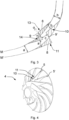
- FIG. 3 The corresponding design of the housing wall 3 and the blade upper edges the blades 5 is more detailed in Figure 3 shown.
- the adjustment of the meridian contour with recess 11 and elevation 10 of the blade upper edge compared to the meridian course M' as well as the meridian contour with recess 14 and elevation 13 of the housing wall 3 compared to the meridian course M can be clearly seen.
- the hatched areas determine the respective size of the deviations from the continuous meridian courses M , M'.
- Figure 3 also the head gap width a, b determined by the distance between the upper edge of the blade 5 and the housing wall 3 and the head gap length c between the stop surfaces 9, 9' are shown, whereby in the embodiment shown a>c>b.
- the elevation 14 of the housing wall 3 and the recess 11 of the upper edge of the blade as well as the elevation 10 of the upper edge of the blade and the recess 13 of the housing wall 3 are each the same, so that the head gap widths a and b remain constant.
- the Figures 4 and 5 show different embodiments of compressor wheels 4, wherein the compressor wheels 4 each have blades 5 with different axial extensions, which are arranged alternately in the circumferential direction and are curved in the circumferential direction.
- the blades with shorter axial extension or meridional extension are arranged as intermediate blades 5' between the blades 5 with greater axial extension or meridional extension.
- the curved course of the longer blades 5 means that the intermediate blades 5' are covered in axial projection.
- Both the blades 5 and the intermediate blades 5' are designed with the elevation 10 and recess 11, but only the blades 5 can be shaped accordingly and the intermediate blades 5' can have a continuous meridian contour.
- the design of the compressor wheel 4 according to Figure 5 differs in that the discontinuous meridian contour of the upper edges of the blades is formed several times over the meridian course.
- the housing wall 3 is then formed accordingly in a complementary manner.
Landscapes
- Engineering & Computer Science (AREA)
- Mechanical Engineering (AREA)
- General Engineering & Computer Science (AREA)
- Structures Of Non-Positive Displacement Pumps (AREA)
Claims (9)
- Turbocompresseur (1), comprenant un carter de compresseur (2) et une roue de compresseur (4) pourvue d'aubes (5), dans lequel la roue de compresseur (4) est montée rotative par rapport au carter de compresseur (2) et est espacée par un entrefer de tête (7) entre des bords supérieurs d'aube sans recouvrement des aubes (5) et une paroi de compresseur (3), tournée vers les bords supérieurs d'aube, du carter de compresseur (2), dans lequel à la fois les bords supérieurs d'aube des aubes (5) et la paroi de carter (3) présentent respectivement sur leur contour méridien respectif au moins un retrait (11, 13) ainsi qu'au moins un relief (10, 14) qui coopèrent localement de sorte que l'entrefer de tête (7), vu dans la zone des retraits (11, 13) et des reliefs (10, 14) dans un plan méridien, détermine un tracé en forme de Z, dans lequel la paroi de carter (3) et les aubes (5) présentent respectivement des surfaces de butée (9, 9') tournées les unes vers les autres pour un écoulement à travers l'entrefer de tête (7), dans lequel les surfaces de butée (9, 9') s'étendent par rapport à une verticale à une tangente (T) du tracé méridien de la paroi de carter (3) et/ou des bords supérieurs d'aube de la roue de compresseur (4) en parallèle à un angle α = ±15°.
- Turbocompresseur selon la revendication 1, caractérisé en ce qu'une longueur méridienne (L) de la roue de compresseur est déterminée à partir de son bord d'attaque (12) côté admission jusqu'au bord de fuite (6) côté soufflage entre les valeurs 0 < L < 1, et ledit au moins un retrait ainsi que ledit au moins un relief sont réalisés dans une plage de 0,3 < L < 0,7, en particulier de 0,4 < L < 0,5.
- Turbocompresseur selon l'une quelconque des revendications précédentes, caractérisé en ce que l'entrefer de tête (7) présente une largeur d'entrefer de tête constante, la largeur d'entrefer de tête étant déterminée par l'espacement entre le bord supérieur d'aube et la paroi de carter.
- Turbocompresseur selon l'une quelconque des revendications précédentes 1 ou 2, caractérisé en ce que l'entrefer de tête (7) présente dans une partie adjacente au bord d'aube (12) côté admission une première largeur d'entrefer de tête (a), dans une partie adjacente au bord d'aube (6) côté soufflage une deuxième largeur d'entrefer de tête (b) et dans une zone du retrait ou du relief une longueur d'entrefer de tête radiale (c) s'étendant entre les surfaces de butée, où : a < c < b.
- Turbocompresseur selon l'une quelconque des revendications précédentes 1 ou 2, caractérisé en ce que l'entrefer de tête (7) présente dans une partie adjacente au bord d'aube (12) côté admission une première largeur d'entrefer de tête (a), dans une partie adjacente au bord d'aube (6) côté soufflage une deuxième largeur d'entrefer de tête (b) et dans une zone du retrait et du relief une longueur de tête radiale (c) s'étendant entre les surfaces de butée, où : a > c > b.
- Turbocompresseur selon l'une quelconque des revendications précédentes, caractérisé en ce qu'à la fois les bords supérieurs d'aube des aubes (5) et la paroi de carter (3) présentent respectivement sur leur contour méridien respectif plusieurs retraits (11, 13) ainsi que plusieurs reliefs (10, 14) qui coopèrent respectivement localement de sorte que l'entrefer de tête (7), vu dans la zone des retraits et des reliefs dans le plan méridien, détermine un tracé en forme de Z répétitif.
- Turbocompresseur selon l'une quelconque des revendications précédentes, caractérisé en ce que la roue de compresseur (4) présente des aubes (5) d'une étendue axiale respectivement différente, qui sont disposées dans la direction circonférentielle en alternance les unes avec les autres et sont courbées dans la direction circonférentielle.
- Turbocompresseur selon la revendication précédente, caractérisé en ce que les aubes ayant une étendue axiale plus courte sont disposées en tant qu'aubes intermédiaires (5') entre des aubes (5) ayant une étendue axiale plus grande, et les aubes (5) ayant une étendue axiale plus grande recouvrent les aubes intermédiaires (5') dans une vue de dessus axiale côté admission de la roue de compresseur (4).
- Turbocompresseur selon la revendication précédente, caractérisé en ce qu'au moins ou exclusivement les aubes (5) ayant une étendue axiale plus grande présentent sur leur contour méridien respectif ledit au moins un retrait (11) ainsi qu'au moins un relief (10).
Applications Claiming Priority (2)
| Application Number | Priority Date | Filing Date | Title |
|---|---|---|---|
| DE102018132978.4A DE102018132978A1 (de) | 2018-12-19 | 2018-12-19 | Turboverdichter mit angepasster Meridiankontur der Schaufeln und Verdichterwand |
| PCT/EP2019/083080 WO2020126413A1 (fr) | 2018-12-19 | 2019-11-29 | Turbocompresseur avec contour méridien adapté des aubes et de la paroi du compresseur |
Publications (2)
| Publication Number | Publication Date |
|---|---|
| EP3853483A1 EP3853483A1 (fr) | 2021-07-28 |
| EP3853483B1 true EP3853483B1 (fr) | 2025-02-26 |
Family
ID=68771635
Family Applications (1)
| Application Number | Title | Priority Date | Filing Date |
|---|---|---|---|
| EP19813771.3A Active EP3853483B1 (fr) | 2018-12-19 | 2019-11-29 | Turbocompresseur avec contour méridien adapté des aubes et de la paroi du compresseur |
Country Status (5)
| Country | Link |
|---|---|
| US (1) | US11555507B2 (fr) |
| EP (1) | EP3853483B1 (fr) |
| CN (2) | CN210033936U (fr) |
| DE (1) | DE102018132978A1 (fr) |
| WO (1) | WO2020126413A1 (fr) |
Families Citing this family (2)
| Publication number | Priority date | Publication date | Assignee | Title |
|---|---|---|---|---|
| DE102018132978A1 (de) * | 2018-12-19 | 2020-06-25 | Ebm-Papst Mulfingen Gmbh & Co. Kg | Turboverdichter mit angepasster Meridiankontur der Schaufeln und Verdichterwand |
| CN116146503A (zh) * | 2023-02-23 | 2023-05-23 | 安徽美芝精密制造有限公司 | 压缩机、空调器、燃料电池模组和车辆 |
Citations (2)
| Publication number | Priority date | Publication date | Assignee | Title |
|---|---|---|---|---|
| FR893205A (fr) * | 1942-12-18 | 1944-06-02 | Perfectionnements aux turbo-machines telles que les compresseurs et les pompes centrifuges | |
| DE1057137B (de) * | 1958-03-07 | 1959-05-14 | Maschf Augsburg Nuernberg Ag | Schaufelspaltdichtung bei Kreiselradmaschinen mit deckband- oder deckenscheibenlosenLaufraedern |
Family Cites Families (23)
| Publication number | Priority date | Publication date | Assignee | Title |
|---|---|---|---|---|
| US2737898A (en) * | 1949-09-28 | 1956-03-13 | Andermatt Carl | Centrifugal pump |
| US4093401A (en) * | 1976-04-12 | 1978-06-06 | Sundstrand Corporation | Compressor impeller and method of manufacture |
| DE59208865D1 (de) * | 1992-12-08 | 1997-10-09 | Asea Brown Boveri | Stabilierungseinrichtung zur Kennfelderweiterung eines Verdichters |
| JP2002021791A (ja) * | 2000-07-10 | 2002-01-23 | Mitsubishi Heavy Ind Ltd | ターボ形圧縮機 |
| US7255531B2 (en) * | 2003-12-17 | 2007-08-14 | Watson Cogeneration Company | Gas turbine tip shroud rails |
| EP2290205A1 (fr) * | 2008-06-17 | 2011-03-02 | IHI Corporation | Boîtier de compresseur pour turbocompresseur |
| CN104204453B (zh) * | 2012-04-23 | 2019-03-08 | 博格华纳公司 | 带横向凹槽的涡轮增压器护罩以及结合有该护罩的涡轮增压器 |
| CN104364493B (zh) * | 2012-06-25 | 2018-05-15 | 博格华纳公司 | 排气涡轮增压器 |
| CN104507607B (zh) * | 2012-08-01 | 2016-12-28 | 三菱重工业株式会社 | 压缩机用叶轮的制造方法及压缩机用叶轮 |
| CN102817873B (zh) * | 2012-08-10 | 2015-07-15 | 势加透博(北京)科技有限公司 | 航空发动机压气机的梯状间隙结构 |
| DE102013201771A1 (de) * | 2013-02-04 | 2014-08-07 | Bosch Mahle Turbo Systems Gmbh & Co. Kg | Verdichter eines Abgasturboladers |
| DE102013201763A1 (de) * | 2013-02-04 | 2014-08-07 | Bosch Mahle Turbo Systems Gmbh & Co. Kg | Verdichter eines Abgasturboladers |
| KR101477420B1 (ko) * | 2013-09-09 | 2014-12-29 | (주)계양정밀 | 공기유동부가 형성된 터보차져 컴프레서 |
| DE102014222877A1 (de) * | 2014-11-10 | 2016-05-12 | Siemens Aktiengesellschaft | Laufrad einer Radialturbofluidenergiemaschine, Stufe |
| DE102014226341A1 (de) * | 2014-12-18 | 2016-06-23 | Volkswagen Aktiengesellschaft | Verdichter, Abgasturbolader und Brennkraftmaschine |
| JP6369621B2 (ja) * | 2015-02-18 | 2018-08-08 | 株式会社Ihi | 遠心圧縮機および過給機 |
| CN107438717B (zh) * | 2015-04-15 | 2021-10-08 | 罗伯特·博世有限公司 | 自由梢端型轴流式风扇组件 |
| JP2017057779A (ja) * | 2015-09-16 | 2017-03-23 | 株式会社豊田自動織機 | ターボチャージャ |
| US10167875B2 (en) * | 2016-01-04 | 2019-01-01 | Caterpillar Inc. | Turbocharger compressor and method |
| US10221858B2 (en) * | 2016-01-08 | 2019-03-05 | Rolls-Royce Corporation | Impeller blade morphology |
| DE102016001484A1 (de) * | 2016-02-11 | 2017-08-17 | Ebm-Papst St. Georgen Gmbh & Co. Kg | Lüftereinheit |
| JP6623138B2 (ja) * | 2016-10-13 | 2019-12-18 | 株式会社神戸製鋼所 | ラビリンスシール |
| DE102018132978A1 (de) * | 2018-12-19 | 2020-06-25 | Ebm-Papst Mulfingen Gmbh & Co. Kg | Turboverdichter mit angepasster Meridiankontur der Schaufeln und Verdichterwand |
-
2018
- 2018-12-19 DE DE102018132978.4A patent/DE102018132978A1/de not_active Withdrawn
-
2019
- 2019-01-24 CN CN201920124164.3U patent/CN210033936U/zh not_active Expired - Fee Related
- 2019-11-29 WO PCT/EP2019/083080 patent/WO2020126413A1/fr not_active Ceased
- 2019-11-29 US US17/312,511 patent/US11555507B2/en active Active
- 2019-11-29 CN CN201980077274.1A patent/CN113167287B/zh active Active
- 2019-11-29 EP EP19813771.3A patent/EP3853483B1/fr active Active
Patent Citations (2)
| Publication number | Priority date | Publication date | Assignee | Title |
|---|---|---|---|---|
| FR893205A (fr) * | 1942-12-18 | 1944-06-02 | Perfectionnements aux turbo-machines telles que les compresseurs et les pompes centrifuges | |
| DE1057137B (de) * | 1958-03-07 | 1959-05-14 | Maschf Augsburg Nuernberg Ag | Schaufelspaltdichtung bei Kreiselradmaschinen mit deckband- oder deckenscheibenlosenLaufraedern |
Also Published As
| Publication number | Publication date |
|---|---|
| DE102018132978A1 (de) | 2020-06-25 |
| CN113167287B (zh) | 2023-06-30 |
| US11555507B2 (en) | 2023-01-17 |
| WO2020126413A1 (fr) | 2020-06-25 |
| CN210033936U (zh) | 2020-02-07 |
| US20220049712A1 (en) | 2022-02-17 |
| CN113167287A (zh) | 2021-07-23 |
| EP3853483A1 (fr) | 2021-07-28 |
Similar Documents
| Publication | Publication Date | Title |
|---|---|---|
| DE69915283T2 (de) | Kreiselrad für turbomaschinen | |
| EP3655664B1 (fr) | Pale pour rotor de ventilateur, rotor et ventilateur axial, ventilateur diagonal ou ventilateur radial | |
| EP2025945B1 (fr) | Machine de traitement des écoulements dotée d'un creux de paroi de canal de ceinture | |
| EP1801422B1 (fr) | Ventilateur et aube de ventilateur | |
| EP2189664B1 (fr) | Tuyère d'éjection à géométrie variable à aubes multiples pour turbomachine | |
| DE2744366A1 (de) | Laufrad fuer einen radialen turboverdichter | |
| EP3702620B1 (fr) | Ventilateur axial pourvu d'aubes de roue de ventilateur réduisant le bruit et pourvues de trous | |
| EP2275643B1 (fr) | Aube de moteur dotée d'une charge de rebords avant surélevée | |
| EP1632662B1 (fr) | Turbomachine avec soutirage | |
| EP3289224A1 (fr) | Hélice de ventilateur et système comprenant au moins un ventilateur | |
| DE202004010088U1 (de) | Laufrad, insbesondere für einen Axialventilator | |
| EP1918529A2 (fr) | Turbomachine avec aubes statoriques ajustables | |
| EP3655665A2 (fr) | Carter pour une turbomachine, notamment pour un ventilateur radial | |
| EP3853483B1 (fr) | Turbocompresseur avec contour méridien adapté des aubes et de la paroi du compresseur | |
| DE19722353A1 (de) | Kreiselpumpe mit einer Einlaufleiteinrichtung | |
| EP2568166B1 (fr) | Pale de rotor d'éolienne dotée d'un rebord arrière à profil épais | |
| EP4090853A1 (fr) | Boîtier pour un ventilateur et ventilateur doté d'un boîtier correspondant | |
| EP3592987B1 (fr) | Carter semi-hélicoïdal | |
| EP3088743B1 (fr) | Étage de pompe a vide à canal latéral avec un barrage de canal qui présente une rampe du côté de l'aspiration | |
| DE68915278T2 (de) | Leitschaufel für axialgebläse. | |
| DE102019115011A1 (de) | Verdichter mit Einlasseinsatz und Rückführungskanal | |
| EP3032107A2 (fr) | Pompe turbomoleculaire | |
| DE202018107293U1 (de) | Turboverdichter mit angepasster Meridiankontur der Schaufeln und Verdichterwand | |
| EP3369892B1 (fr) | Contournage d'une plate-forme de grille d'aube | |
| DE102005040305B4 (de) | Seitenkanalmaschine |
Legal Events
| Date | Code | Title | Description |
|---|---|---|---|
| STAA | Information on the status of an ep patent application or granted ep patent |
Free format text: STATUS: UNKNOWN |
|
| STAA | Information on the status of an ep patent application or granted ep patent |
Free format text: STATUS: THE INTERNATIONAL PUBLICATION HAS BEEN MADE |
|
| PUAI | Public reference made under article 153(3) epc to a published international application that has entered the european phase |
Free format text: ORIGINAL CODE: 0009012 |
|
| STAA | Information on the status of an ep patent application or granted ep patent |
Free format text: STATUS: REQUEST FOR EXAMINATION WAS MADE |
|
| 17P | Request for examination filed |
Effective date: 20210419 |
|
| AK | Designated contracting states |
Kind code of ref document: A1 Designated state(s): AL AT BE BG CH CY CZ DE DK EE ES FI FR GB GR HR HU IE IS IT LI LT LU LV MC MK MT NL NO PL PT RO RS SE SI SK SM TR |
|
| DAV | Request for validation of the european patent (deleted) | ||
| DAX | Request for extension of the european patent (deleted) | ||
| STAA | Information on the status of an ep patent application or granted ep patent |
Free format text: STATUS: EXAMINATION IS IN PROGRESS |
|
| 17Q | First examination report despatched |
Effective date: 20230420 |
|
| GRAP | Despatch of communication of intention to grant a patent |
Free format text: ORIGINAL CODE: EPIDOSNIGR1 |
|
| STAA | Information on the status of an ep patent application or granted ep patent |
Free format text: STATUS: GRANT OF PATENT IS INTENDED |
|
| INTG | Intention to grant announced |
Effective date: 20241125 |
|
| GRAS | Grant fee paid |
Free format text: ORIGINAL CODE: EPIDOSNIGR3 |
|
| GRAA | (expected) grant |
Free format text: ORIGINAL CODE: 0009210 |
|
| STAA | Information on the status of an ep patent application or granted ep patent |
Free format text: STATUS: THE PATENT HAS BEEN GRANTED |
|
| P01 | Opt-out of the competence of the unified patent court (upc) registered |
Free format text: CASE NUMBER: APP_68624/2024 Effective date: 20241230 |
|
| AK | Designated contracting states |
Kind code of ref document: B1 Designated state(s): AL AT BE BG CH CY CZ DE DK EE ES FI FR GB GR HR HU IE IS IT LI LT LU LV MC MK MT NL NO PL PT RO RS SE SI SK SM TR |
|
| REG | Reference to a national code |
Ref country code: GB Ref legal event code: FG4D Free format text: NOT ENGLISH |
|
| REG | Reference to a national code |
Ref country code: CH Ref legal event code: EP |
|
| REG | Reference to a national code |
Ref country code: DE Ref legal event code: R096 Ref document number: 502019013003 Country of ref document: DE |
|
| REG | Reference to a national code |
Ref country code: IE Ref legal event code: FG4D Free format text: LANGUAGE OF EP DOCUMENT: GERMAN |
|
| REG | Reference to a national code |
Ref country code: NL Ref legal event code: MP Effective date: 20250226 |
|
| PG25 | Lapsed in a contracting state [announced via postgrant information from national office to epo] |
Ref country code: RS Free format text: LAPSE BECAUSE OF FAILURE TO SUBMIT A TRANSLATION OF THE DESCRIPTION OR TO PAY THE FEE WITHIN THE PRESCRIBED TIME-LIMIT Effective date: 20250526 |
|
| PG25 | Lapsed in a contracting state [announced via postgrant information from national office to epo] |
Ref country code: FI Free format text: LAPSE BECAUSE OF FAILURE TO SUBMIT A TRANSLATION OF THE DESCRIPTION OR TO PAY THE FEE WITHIN THE PRESCRIBED TIME-LIMIT Effective date: 20250226 |
|
| PG25 | Lapsed in a contracting state [announced via postgrant information from national office to epo] |
Ref country code: PL Free format text: LAPSE BECAUSE OF FAILURE TO SUBMIT A TRANSLATION OF THE DESCRIPTION OR TO PAY THE FEE WITHIN THE PRESCRIBED TIME-LIMIT Effective date: 20250226 |
|
| PG25 | Lapsed in a contracting state [announced via postgrant information from national office to epo] |
Ref country code: ES Free format text: LAPSE BECAUSE OF FAILURE TO SUBMIT A TRANSLATION OF THE DESCRIPTION OR TO PAY THE FEE WITHIN THE PRESCRIBED TIME-LIMIT Effective date: 20250226 |
|
| REG | Reference to a national code |
Ref country code: LT Ref legal event code: MG9D |
|
| PG25 | Lapsed in a contracting state [announced via postgrant information from national office to epo] |
Ref country code: NO Free format text: LAPSE BECAUSE OF FAILURE TO SUBMIT A TRANSLATION OF THE DESCRIPTION OR TO PAY THE FEE WITHIN THE PRESCRIBED TIME-LIMIT Effective date: 20250526 Ref country code: IS Free format text: LAPSE BECAUSE OF FAILURE TO SUBMIT A TRANSLATION OF THE DESCRIPTION OR TO PAY THE FEE WITHIN THE PRESCRIBED TIME-LIMIT Effective date: 20250626 |
|
| PG25 | Lapsed in a contracting state [announced via postgrant information from national office to epo] |
Ref country code: NL Free format text: LAPSE BECAUSE OF FAILURE TO SUBMIT A TRANSLATION OF THE DESCRIPTION OR TO PAY THE FEE WITHIN THE PRESCRIBED TIME-LIMIT Effective date: 20250226 |
|
| PG25 | Lapsed in a contracting state [announced via postgrant information from national office to epo] |
Ref country code: HR Free format text: LAPSE BECAUSE OF FAILURE TO SUBMIT A TRANSLATION OF THE DESCRIPTION OR TO PAY THE FEE WITHIN THE PRESCRIBED TIME-LIMIT Effective date: 20250226 |
|
| PG25 | Lapsed in a contracting state [announced via postgrant information from national office to epo] |
Ref country code: PT Free format text: LAPSE BECAUSE OF FAILURE TO SUBMIT A TRANSLATION OF THE DESCRIPTION OR TO PAY THE FEE WITHIN THE PRESCRIBED TIME-LIMIT Effective date: 20250626 Ref country code: LV Free format text: LAPSE BECAUSE OF FAILURE TO SUBMIT A TRANSLATION OF THE DESCRIPTION OR TO PAY THE FEE WITHIN THE PRESCRIBED TIME-LIMIT Effective date: 20250226 |
|
| PG25 | Lapsed in a contracting state [announced via postgrant information from national office to epo] |
Ref country code: BG Free format text: LAPSE BECAUSE OF FAILURE TO SUBMIT A TRANSLATION OF THE DESCRIPTION OR TO PAY THE FEE WITHIN THE PRESCRIBED TIME-LIMIT Effective date: 20250226 Ref country code: GR Free format text: LAPSE BECAUSE OF FAILURE TO SUBMIT A TRANSLATION OF THE DESCRIPTION OR TO PAY THE FEE WITHIN THE PRESCRIBED TIME-LIMIT Effective date: 20250527 |
|
| PG25 | Lapsed in a contracting state [announced via postgrant information from national office to epo] |
Ref country code: SE Free format text: LAPSE BECAUSE OF FAILURE TO SUBMIT A TRANSLATION OF THE DESCRIPTION OR TO PAY THE FEE WITHIN THE PRESCRIBED TIME-LIMIT Effective date: 20250226 |
|
| PG25 | Lapsed in a contracting state [announced via postgrant information from national office to epo] |
Ref country code: SM Free format text: LAPSE BECAUSE OF FAILURE TO SUBMIT A TRANSLATION OF THE DESCRIPTION OR TO PAY THE FEE WITHIN THE PRESCRIBED TIME-LIMIT Effective date: 20250226 |
|
| PG25 | Lapsed in a contracting state [announced via postgrant information from national office to epo] |
Ref country code: DK Free format text: LAPSE BECAUSE OF FAILURE TO SUBMIT A TRANSLATION OF THE DESCRIPTION OR TO PAY THE FEE WITHIN THE PRESCRIBED TIME-LIMIT Effective date: 20250226 |
|
| PG25 | Lapsed in a contracting state [announced via postgrant information from national office to epo] |
Ref country code: IT Free format text: LAPSE BECAUSE OF FAILURE TO SUBMIT A TRANSLATION OF THE DESCRIPTION OR TO PAY THE FEE WITHIN THE PRESCRIBED TIME-LIMIT Effective date: 20250226 |
|
| PG25 | Lapsed in a contracting state [announced via postgrant information from national office to epo] |
Ref country code: EE Free format text: LAPSE BECAUSE OF FAILURE TO SUBMIT A TRANSLATION OF THE DESCRIPTION OR TO PAY THE FEE WITHIN THE PRESCRIBED TIME-LIMIT Effective date: 20250226 Ref country code: CZ Free format text: LAPSE BECAUSE OF FAILURE TO SUBMIT A TRANSLATION OF THE DESCRIPTION OR TO PAY THE FEE WITHIN THE PRESCRIBED TIME-LIMIT Effective date: 20250226 |
|
| PG25 | Lapsed in a contracting state [announced via postgrant information from national office to epo] |
Ref country code: RO Free format text: LAPSE BECAUSE OF FAILURE TO SUBMIT A TRANSLATION OF THE DESCRIPTION OR TO PAY THE FEE WITHIN THE PRESCRIBED TIME-LIMIT Effective date: 20250226 |
|
| PG25 | Lapsed in a contracting state [announced via postgrant information from national office to epo] |
Ref country code: SK Free format text: LAPSE BECAUSE OF FAILURE TO SUBMIT A TRANSLATION OF THE DESCRIPTION OR TO PAY THE FEE WITHIN THE PRESCRIBED TIME-LIMIT Effective date: 20250226 |
|
| REG | Reference to a national code |
Ref country code: DE Ref legal event code: R097 Ref document number: 502019013003 Country of ref document: DE |
|
| PLBE | No opposition filed within time limit |
Free format text: ORIGINAL CODE: 0009261 |
|
| STAA | Information on the status of an ep patent application or granted ep patent |
Free format text: STATUS: NO OPPOSITION FILED WITHIN TIME LIMIT |
|
| PGFP | Annual fee paid to national office [announced via postgrant information from national office to epo] |
Ref country code: DE Payment date: 20251118 Year of fee payment: 7 |
|
| 26N | No opposition filed |
Effective date: 20251127 |