EP3853518B1 - Lichtmodul, insbesondere zur verwendung in einer beleuchtungsvorrichtung für ein kraftfahrzeug - Google Patents
Lichtmodul, insbesondere zur verwendung in einer beleuchtungsvorrichtung für ein kraftfahrzeug Download PDFInfo
- Publication number
- EP3853518B1 EP3853518B1 EP19773759.6A EP19773759A EP3853518B1 EP 3853518 B1 EP3853518 B1 EP 3853518B1 EP 19773759 A EP19773759 A EP 19773759A EP 3853518 B1 EP3853518 B1 EP 3853518B1
- Authority
- EP
- European Patent Office
- Prior art keywords
- light
- frame
- unit
- emitting means
- type component
- Prior art date
- Legal status (The legal status is an assumption and is not a legal conclusion. Google has not performed a legal analysis and makes no representation as to the accuracy of the status listed.)
- Active
Links
Images



Classifications
-
- F—MECHANICAL ENGINEERING; LIGHTING; HEATING; WEAPONS; BLASTING
- F21—LIGHTING
- F21S—NON-PORTABLE LIGHTING DEVICES; SYSTEMS THEREOF; VEHICLE LIGHTING DEVICES SPECIALLY ADAPTED FOR VEHICLE EXTERIORS
- F21S43/00—Signalling devices specially adapted for vehicle exteriors, e.g. brake lamps, direction indicator lights or reversing lights
- F21S43/10—Signalling devices specially adapted for vehicle exteriors, e.g. brake lamps, direction indicator lights or reversing lights characterised by the light source
- F21S43/13—Signalling devices specially adapted for vehicle exteriors, e.g. brake lamps, direction indicator lights or reversing lights characterised by the light source characterised by the type of light source
- F21S43/14—Light emitting diodes [LED]
-
- F—MECHANICAL ENGINEERING; LIGHTING; HEATING; WEAPONS; BLASTING
- F21—LIGHTING
- F21S—NON-PORTABLE LIGHTING DEVICES; SYSTEMS THEREOF; VEHICLE LIGHTING DEVICES SPECIALLY ADAPTED FOR VEHICLE EXTERIORS
- F21S43/00—Signalling devices specially adapted for vehicle exteriors, e.g. brake lamps, direction indicator lights or reversing lights
- F21S43/40—Signalling devices specially adapted for vehicle exteriors, e.g. brake lamps, direction indicator lights or reversing lights characterised by the combination of reflectors and refractors
- F21S43/402—Total internal reflection [TIR] collimators
-
- F—MECHANICAL ENGINEERING; LIGHTING; HEATING; WEAPONS; BLASTING
- F21—LIGHTING
- F21S—NON-PORTABLE LIGHTING DEVICES; SYSTEMS THEREOF; VEHICLE LIGHTING DEVICES SPECIALLY ADAPTED FOR VEHICLE EXTERIORS
- F21S43/00—Signalling devices specially adapted for vehicle exteriors, e.g. brake lamps, direction indicator lights or reversing lights
- F21S43/10—Signalling devices specially adapted for vehicle exteriors, e.g. brake lamps, direction indicator lights or reversing lights characterised by the light source
- F21S43/13—Signalling devices specially adapted for vehicle exteriors, e.g. brake lamps, direction indicator lights or reversing lights characterised by the light source characterised by the type of light source
- F21S43/15—Strips of light sources
-
- F—MECHANICAL ENGINEERING; LIGHTING; HEATING; WEAPONS; BLASTING
- F21—LIGHTING
- F21S—NON-PORTABLE LIGHTING DEVICES; SYSTEMS THEREOF; VEHICLE LIGHTING DEVICES SPECIALLY ADAPTED FOR VEHICLE EXTERIORS
- F21S43/00—Signalling devices specially adapted for vehicle exteriors, e.g. brake lamps, direction indicator lights or reversing lights
- F21S43/10—Signalling devices specially adapted for vehicle exteriors, e.g. brake lamps, direction indicator lights or reversing lights characterised by the light source
- F21S43/19—Attachment of light sources or lamp holders
-
- F—MECHANICAL ENGINEERING; LIGHTING; HEATING; WEAPONS; BLASTING
- F21—LIGHTING
- F21S—NON-PORTABLE LIGHTING DEVICES; SYSTEMS THEREOF; VEHICLE LIGHTING DEVICES SPECIALLY ADAPTED FOR VEHICLE EXTERIORS
- F21S43/00—Signalling devices specially adapted for vehicle exteriors, e.g. brake lamps, direction indicator lights or reversing lights
- F21S43/20—Signalling devices specially adapted for vehicle exteriors, e.g. brake lamps, direction indicator lights or reversing lights characterised by refractors, transparent cover plates, light guides or filters
- F21S43/235—Light guides
- F21S43/236—Light guides characterised by the shape of the light guide
- F21S43/239—Light guides characterised by the shape of the light guide plate-shaped
-
- F—MECHANICAL ENGINEERING; LIGHTING; HEATING; WEAPONS; BLASTING
- F21—LIGHTING
- F21S—NON-PORTABLE LIGHTING DEVICES; SYSTEMS THEREOF; VEHICLE LIGHTING DEVICES SPECIALLY ADAPTED FOR VEHICLE EXTERIORS
- F21S43/00—Signalling devices specially adapted for vehicle exteriors, e.g. brake lamps, direction indicator lights or reversing lights
- F21S43/20—Signalling devices specially adapted for vehicle exteriors, e.g. brake lamps, direction indicator lights or reversing lights characterised by refractors, transparent cover plates, light guides or filters
- F21S43/235—Light guides
- F21S43/242—Light guides characterised by the emission area
- F21S43/245—Light guides characterised by the emission area emitting light from one or more of its major surfaces
-
- F—MECHANICAL ENGINEERING; LIGHTING; HEATING; WEAPONS; BLASTING
- F21—LIGHTING
- F21S—NON-PORTABLE LIGHTING DEVICES; SYSTEMS THEREOF; VEHICLE LIGHTING DEVICES SPECIALLY ADAPTED FOR VEHICLE EXTERIORS
- F21S43/00—Signalling devices specially adapted for vehicle exteriors, e.g. brake lamps, direction indicator lights or reversing lights
- F21S43/20—Signalling devices specially adapted for vehicle exteriors, e.g. brake lamps, direction indicator lights or reversing lights characterised by refractors, transparent cover plates, light guides or filters
- F21S43/235—Light guides
- F21S43/242—Light guides characterised by the emission area
- F21S43/246—Light guides characterised by the emission area having two or more output branches
-
- F—MECHANICAL ENGINEERING; LIGHTING; HEATING; WEAPONS; BLASTING
- F21—LIGHTING
- F21S—NON-PORTABLE LIGHTING DEVICES; SYSTEMS THEREOF; VEHICLE LIGHTING DEVICES SPECIALLY ADAPTED FOR VEHICLE EXTERIORS
- F21S43/00—Signalling devices specially adapted for vehicle exteriors, e.g. brake lamps, direction indicator lights or reversing lights
- F21S43/20—Signalling devices specially adapted for vehicle exteriors, e.g. brake lamps, direction indicator lights or reversing lights characterised by refractors, transparent cover plates, light guides or filters
- F21S43/235—Light guides
- F21S43/249—Light guides with two or more light sources being coupled into the light guide
-
- F—MECHANICAL ENGINEERING; LIGHTING; HEATING; WEAPONS; BLASTING
- F21—LIGHTING
- F21S—NON-PORTABLE LIGHTING DEVICES; SYSTEMS THEREOF; VEHICLE LIGHTING DEVICES SPECIALLY ADAPTED FOR VEHICLE EXTERIORS
- F21S43/00—Signalling devices specially adapted for vehicle exteriors, e.g. brake lamps, direction indicator lights or reversing lights
- F21S43/20—Signalling devices specially adapted for vehicle exteriors, e.g. brake lamps, direction indicator lights or reversing lights characterised by refractors, transparent cover plates, light guides or filters
- F21S43/235—Light guides
- F21S43/249—Light guides with two or more light sources being coupled into the light guide
- F21S43/2492—Light guides with two or more light sources being coupled into the light guide having two or more input branches
-
- F—MECHANICAL ENGINEERING; LIGHTING; HEATING; WEAPONS; BLASTING
- F21—LIGHTING
- F21S—NON-PORTABLE LIGHTING DEVICES; SYSTEMS THEREOF; VEHICLE LIGHTING DEVICES SPECIALLY ADAPTED FOR VEHICLE EXTERIORS
- F21S43/00—Signalling devices specially adapted for vehicle exteriors, e.g. brake lamps, direction indicator lights or reversing lights
- F21S43/20—Signalling devices specially adapted for vehicle exteriors, e.g. brake lamps, direction indicator lights or reversing lights characterised by refractors, transparent cover plates, light guides or filters
- F21S43/235—Light guides
- F21S43/252—Two or more successive light guides
-
- F—MECHANICAL ENGINEERING; LIGHTING; HEATING; WEAPONS; BLASTING
- F21—LIGHTING
- F21S—NON-PORTABLE LIGHTING DEVICES; SYSTEMS THEREOF; VEHICLE LIGHTING DEVICES SPECIALLY ADAPTED FOR VEHICLE EXTERIORS
- F21S43/00—Signalling devices specially adapted for vehicle exteriors, e.g. brake lamps, direction indicator lights or reversing lights
- F21S43/30—Signalling devices specially adapted for vehicle exteriors, e.g. brake lamps, direction indicator lights or reversing lights characterised by reflectors
-
- F—MECHANICAL ENGINEERING; LIGHTING; HEATING; WEAPONS; BLASTING
- F21—LIGHTING
- F21S—NON-PORTABLE LIGHTING DEVICES; SYSTEMS THEREOF; VEHICLE LIGHTING DEVICES SPECIALLY ADAPTED FOR VEHICLE EXTERIORS
- F21S43/00—Signalling devices specially adapted for vehicle exteriors, e.g. brake lamps, direction indicator lights or reversing lights
- F21S43/30—Signalling devices specially adapted for vehicle exteriors, e.g. brake lamps, direction indicator lights or reversing lights characterised by reflectors
- F21S43/37—Attachment thereof
-
- F—MECHANICAL ENGINEERING; LIGHTING; HEATING; WEAPONS; BLASTING
- F21—LIGHTING
- F21S—NON-PORTABLE LIGHTING DEVICES; SYSTEMS THEREOF; VEHICLE LIGHTING DEVICES SPECIALLY ADAPTED FOR VEHICLE EXTERIORS
- F21S43/00—Signalling devices specially adapted for vehicle exteriors, e.g. brake lamps, direction indicator lights or reversing lights
- F21S43/40—Signalling devices specially adapted for vehicle exteriors, e.g. brake lamps, direction indicator lights or reversing lights characterised by the combination of reflectors and refractors
-
- F—MECHANICAL ENGINEERING; LIGHTING; HEATING; WEAPONS; BLASTING
- F21—LIGHTING
- F21S—NON-PORTABLE LIGHTING DEVICES; SYSTEMS THEREOF; VEHICLE LIGHTING DEVICES SPECIALLY ADAPTED FOR VEHICLE EXTERIORS
- F21S43/00—Signalling devices specially adapted for vehicle exteriors, e.g. brake lamps, direction indicator lights or reversing lights
- F21S43/50—Signalling devices specially adapted for vehicle exteriors, e.g. brake lamps, direction indicator lights or reversing lights characterised by aesthetic components not otherwise provided for, e.g. decorative trim, partition walls or covers
-
- F—MECHANICAL ENGINEERING; LIGHTING; HEATING; WEAPONS; BLASTING
- F21—LIGHTING
- F21S—NON-PORTABLE LIGHTING DEVICES; SYSTEMS THEREOF; VEHICLE LIGHTING DEVICES SPECIALLY ADAPTED FOR VEHICLE EXTERIORS
- F21S43/00—Signalling devices specially adapted for vehicle exteriors, e.g. brake lamps, direction indicator lights or reversing lights
- F21S43/50—Signalling devices specially adapted for vehicle exteriors, e.g. brake lamps, direction indicator lights or reversing lights characterised by aesthetic components not otherwise provided for, e.g. decorative trim, partition walls or covers
- F21S43/51—Attachment thereof
-
- F—MECHANICAL ENGINEERING; LIGHTING; HEATING; WEAPONS; BLASTING
- F21—LIGHTING
- F21S—NON-PORTABLE LIGHTING DEVICES; SYSTEMS THEREOF; VEHICLE LIGHTING DEVICES SPECIALLY ADAPTED FOR VEHICLE EXTERIORS
- F21S43/00—Signalling devices specially adapted for vehicle exteriors, e.g. brake lamps, direction indicator lights or reversing lights
- F21S43/601—Signalling devices specially adapted for vehicle exteriors, e.g. brake lamps, direction indicator lights or reversing lights characterised by variable optical properties, e.g. involving the use of LCD or movable parts
-
- G—PHYSICS
- G02—OPTICS
- G02B—OPTICAL ELEMENTS, SYSTEMS OR APPARATUS
- G02B6/00—Light guides; Structural details of arrangements comprising light guides and other optical elements, e.g. couplings
- G02B6/0001—Light guides; Structural details of arrangements comprising light guides and other optical elements, e.g. couplings specially adapted for lighting devices or systems
- G02B6/0011—Light guides; Structural details of arrangements comprising light guides and other optical elements, e.g. couplings specially adapted for lighting devices or systems the light guides being planar or of plate-like form
- G02B6/0033—Means for improving the coupling-out of light from the light guide
- G02B6/0035—Means for improving the coupling-out of light from the light guide provided on the surface of the light guide or in the bulk of it
- G02B6/004—Scattering dots or dot-like elements, e.g. microbeads, scattering particles, nanoparticles
- G02B6/0041—Scattering dots or dot-like elements, e.g. microbeads, scattering particles, nanoparticles provided in the bulk of the light guide
-
- G—PHYSICS
- G02—OPTICS
- G02B—OPTICAL ELEMENTS, SYSTEMS OR APPARATUS
- G02B6/00—Light guides; Structural details of arrangements comprising light guides and other optical elements, e.g. couplings
- G02B6/0001—Light guides; Structural details of arrangements comprising light guides and other optical elements, e.g. couplings specially adapted for lighting devices or systems
- G02B6/0011—Light guides; Structural details of arrangements comprising light guides and other optical elements, e.g. couplings specially adapted for lighting devices or systems the light guides being planar or of plate-like form
- G02B6/0033—Means for improving the coupling-out of light from the light guide
- G02B6/005—Means for improving the coupling-out of light from the light guide provided by one optical element, or plurality thereof, placed on the light output side of the light guide
- G02B6/0055—Reflecting element, sheet or layer
-
- B—PERFORMING OPERATIONS; TRANSPORTING
- B60—VEHICLES IN GENERAL
- B60Q—ARRANGEMENT OF SIGNALLING OR LIGHTING DEVICES, THE MOUNTING OR SUPPORTING THEREOF OR CIRCUITS THEREFOR, FOR VEHICLES IN GENERAL
- B60Q2400/00—Special features or arrangements of exterior signal lamps for vehicles
- B60Q2400/40—Welcome lights, i.e. specific or existing exterior lamps to assist leaving or approaching the vehicle
-
- B—PERFORMING OPERATIONS; TRANSPORTING
- B60—VEHICLES IN GENERAL
- B60Q—ARRANGEMENT OF SIGNALLING OR LIGHTING DEVICES, THE MOUNTING OR SUPPORTING THEREOF OR CIRCUITS THEREFOR, FOR VEHICLES IN GENERAL
- B60Q2900/00—Features of lamps not covered by other groups in B60Q
- B60Q2900/40—Several lamps activated in sequence, e.g. sweep effect, progressive activation
Definitions
- the invention relates to a light unit for use in a lighting device for a motor vehicle with the features of the preamble of patent claim 1.
- Such a light unit is from the EP 3 211 298 A1 known.
- a light unit with a light module for a vehicle which has a housing in which a light body designed as a light guide is accommodated.
- Light sources are integrated into the light module, via which light rays are coupled into side surfaces of the light body and can be coupled out via a decoupling structure in the direction of a lens.
- the light body is framed by a reflective frame that delimits a light exit opening in the light exit direction.
- the backlight unit for the exterior mirror of a motor vehicle is described.
- the backlight unit has a housing with a rear wall and a window opposite the rear wall.
- the housing has a side opening into which a stacked assembly can be inserted.
- the assembly also includes a flat light body. After inserting the module into the housing, the side opening is closed by a circuit board with an LED and sealing material.
- the US 2011/216549 A1 a light unit for a motor vehicle can be seen, which can be installed in a lighting device of a motor vehicle.
- the light unit includes an LED light source, in front of which a lens body is arranged.
- the lens body includes a first, a second, a third and a fourth lens part.
- the lens parts are used to converge the light rays emitted by the LED light source.
- the fourth lens part is designed as a flat light guide through which the converged light beams are coupled out at three decoupling points by 90 degrees in the light emission direction of the light unit.
- Several of these light units can be installed in a lighting device with a housing-like reflector. Several of the light units are first mounted on a support part and then pushed from the outside into slot-like openings in the housing-like reflector.
- the light module has an optical waveguide with a light exit surface.
- a light-reflecting or diffusely backscattering film is arranged on the surface of the light module opposite the light exit surface and on the side surfaces of the optical waveguide connecting the light exit surface and the opposite surface.
- a light source for coupling in light from the side is present on one of the side surfaces.
- the surface is provided with alternating light-scattering and flat surfaces. The area ratio of the flat surfaces to the light-scattering surfaces is selected depending on the luminance at the respective location of the optical waveguide.
- the application of the reflective film is practically combined with the production of the optical fiber, which is produced by injection molding. During production, the injection mold is first lined with the film on the bottom surface and at least part of the side surface. When the plastic hardens after injection molding, the film adheres to the optical fiber.
- the light-emitting diodes are used to introduce light into the interior of a hollow body, which has a light-emitting surface for backlighting the information elements.
- a rear wall is formed, which is also light-emitting, self-luminous or simply opaque. Both surfaces are connected to each other by opaque or diffusely reflecting side walls.
- the side walls have light entry openings in which light-emitting diodes or ends of light guides are arranged so that they can feed their light completely into the cavity.
- the opaque wall of the side surfaces consists of a material with a high degree of reflection.
- the light exit surface and the opposite surface are made of light-scattering material with a low degree of absorption.
- OLED organic light-emitting diode
- the present invention is therefore based on the object of providing a light unit with which an OLED lamp can be optically modeled and which is simple and inexpensive to construct.
- the light unit should contribute to simplified assembly when used in a lighting device.
- the invention is based on a light unit with a light module with at least one flat light body and at least one light source, the light rays of which can be or will be coupled into a side surface of the light body, i.e. laterally.
- the coupled light rays can exit to the outside via a light exit surface surrounded by side surfaces of the light body or exit via this. At least part of the side surfaces and a rear surface opposite the light exit surface are covered by a reflective or diffusely backscattering cover.
- Flat in the sense of the invention should mean that the light body has a surface extension that runs in two mutually perpendicular directions and is many times larger in each direction than a thickness of the light guide.
- LED light-emitting diode
- the cover is formed by a frame-like component with a rear wall.
- a side wall of the frame-like component has an opening through which the light body is introduced laterally into the frame-like component.
- the at least one light source is arranged on the side wall of the frame-like component that has the opening.
- light-scattering impurities are distributed in the light body.
- a certain scattering of the light rays coupled into the light body can be achieved, which leads to an improvement in homogeneous light emission through the light module.
- the light-scattering imperfections are distributed throughout the light body and not just on its surface, the light-scattering properties of the light body can be maintained for a long time even in everyday operation of the light module, for example when used in a motor vehicle lighting device.
- the light body When light is coupled in, the light body only has a slightly scattering effect.
- the light body particularly preferably has a transmittance of approximately 92 percent.
- the at least one light source is arranged at a distance from the side wall of the frame-like component, i.e. also at a distance from the light-coupling side surface of the light body.
- the distance is preferably in a range from about 9 millimeters to about 11 millimeters, preferably at a value of about 10 millimeters. This can also contribute to homogeneous light emission from the light module.
- At least one collecting optics or collimation optics be arranged between the at least one lamp and the side wall of the frame-like component.
- light-emitting diodes which are known to have an opening angle of their light emission of up to 180 degrees
- light rays emerging in lateral areas can also be “captured”.
- the frame-like component is attached to a circuit board via a holder, which also carries the at least one light source. This further development contributes to the easy installation of the light module.
- the light module has several lamps designed as light-emitting diodes, which are at a mutual distance of more than 4.5 millimeters and less than 6.5 millimeters. This contributes to homogeneity in the light distribution in the light body and ultimately to homogeneous light emission from the light module.
- the mutual distance between the light-emitting diodes is approximately 5 millimeters.
- the frame-like components on the one hand and the flat light bodies on the other hand are each connected to one another in one piece. Furthermore, the frame-like components are attached to such a common circuit board, which also carries the lighting means assigned to the flat light bodies.
- the present invention is also intended to protect a lighting device for a motor vehicle which has at least one light unit according to the invention.
- a light module 1 can be seen in an exploded view, which comprises a frame-like component 10, a flat light body 30 accommodated therein and a circuit board 50 with lamps 51.
- the frame-like component 10 has a rectangular outline, which is formed by side walls 11, 12, 13 and 14.
- the side walls 11 to 14 are connected to one another in one piece by a rear wall 16.
- the lower side wall 14 in the figure is provided with an opening 15 which is rectangular in outline. Through the opening 15, the flat light body 30 can be pushed into the frame-like component 10 in an insertion direction R. Inside, the component 10 can additionally have guiding and/or holding means (not shown) for the light body 30.
- the light body 30, like the component 10, has a rectangular outline and is flat. It has a surface area F that is several times larger than its thickness d in every direction.
- the dimensions of the light body 30 are such that it essentially fills the frame-like component 10 in its assembly position.
- the light body 30 has side surfaces 31, 32, 33 and 34. These side surfaces surround a light exit surface 35.
- the light exit surface 35 lies opposite a rear surface 36.
- the dimensions of the frame-like component 10 and the light body 30 are preferably selected so that the light body 30 is held securely in the component 10 after it has been inserted. Alternatively, a locking mechanism (not shown in more detail) is also conceivable.
- the light body 30 is designed as a light guide and has a transmittance (light transmittance) in a range from approximately 85 percent to approximately 95 percent.
- the transmittance is particularly preferably approximately 92 percent.
- the only slight scattering property of the light body 30 is caused by light-scattering impurities 38, which are distributed in the light body 30.
- the light-scattering impurities 38 may have been introduced into the light body 30 as interfering particles during production. Alternatively, it is also conceivable to introduce the light-scattering defects into the light body 30 via laser processing.
- the frame-like component 10 is designed to be internally reflective or diffusely backscattering.
- an internal surface 16a of the rear wall 16 can be designed to be reflective or diffusely scattering. This can be achieved, for example, with a white or red coating.
- an internal surface 11a of the side wall 11 can be formed.
- the color of the external surfaces of the frame-like component 10 is preferably designed to be light-tight.
- it can be black.
- Other colors are conceivable.
- the already mentioned circuit board 50 with the lamps 51 designed as light-emitting diodes (LEDs) is arranged at a close distance b below the side wall 14.
- the distance b is preferably approximately 10 millimeters. Furthermore, it can be seen that the lamps 51 have a mutual distance a, which in the exemplary embodiment is preferably approximately 5 millimeters.
- the light body 30 is preferably colored red.
- it can be made of PMMA (polymethyl methacrylate) or PC (polycarbonate).
- the design of the component 10 and the light body 30 means that light rays L coupled into the light body 30 via the lamps 51 "get stuck" on the light-scattering imperfections 38 or are scattered diffusely. This contributes to homogeneous illumination of the light body 38.
- the frame-like component 10 has protruding locking means 18 on its opposite side walls 12, 13.
- the locking means 18 engage in counter-locking means 52 of the resiliently deflectable holders 53.
- collecting optics 60 are indicated by dashed lines between the lower side wall 14 of the component 10 and the lamps 51. These are optional and contribute to the fact that light rays L emitted by the lamps 51 are “collected” and directed in the direction of the light body 30.
- the Fig. 4 a light unit 100 can be seen, which consists of three light modules (as described).
- the components 10, as well as the light bodies 30, can therefore be produced in a simple manner in one operation, preferably in one injection molding tool.
- each of the connecting elements 19 has a curved shape in cross section, so that a semicircular receiving space 19a is created.
- the receiving space 19a serves during assembly to accommodate the connecting element 37, which has a semicircular cross-section (cf Fig. 5 ).
- circuit board 50' which is correspondingly longer than the circuit board 50 (cf. Fig. 1 ) and several, preferably three, light sources 51, which are assigned to the light bodies 30.
- the light modules 1 or light units 100 'or 100" consisting of these can also be used in a lighting device 2 of a motor vehicle indicated by dashed lines.
- the lighting device 2 can be a rear lighting of a motor vehicle, with a body-side part 2a of the lighting device 2 in one Body 3 and a tailgate-side part 2b of the lighting device 2 can be installed in a tailgate 4 of a motor vehicle.
- control unit not shown here, it is conceivable to control the individual light modules 1 one after the other in such a way that lighting animations A1 or A2 (compare arrow direction) are generated. This is conceivable, for example, to implement a so-called coming home or leaving home function.
- FIG. 7 a motor vehicle K, in which two lighting devices 2 serving as rear lights are installed.
- a control unit 5 is used to control the lighting devices 2 via signal and control lines S.
Landscapes
- Engineering & Computer Science (AREA)
- General Engineering & Computer Science (AREA)
- Physics & Mathematics (AREA)
- Optics & Photonics (AREA)
- General Physics & Mathematics (AREA)
- Microelectronics & Electronic Packaging (AREA)
- Non-Portable Lighting Devices Or Systems Thereof (AREA)
- Arrangements Of Lighting Devices For Vehicle Interiors, Mounting And Supporting Thereof, Circuits Therefore (AREA)
- Planar Illumination Modules (AREA)
- Led Device Packages (AREA)
Description
- Die Erfindung betrifft eine Lichteinheit zur Verwendung in einer Beleuchtungsvorrichtung für ein Kraftfahrzeug mit den Merkmalen vom Oberbegriff des Patentanspruchs 1.
- Eine derartige Lichteinheit ist aus der
EP 3 211 298 A1 bekannt. Konkret wird eine Lichteinheit mit einem Lichtmodul für ein Fahrzeug offenbart, welches ein Gehäuse aufweist, in dem ein als Lichtleiter ausgebildeter Lichtkörper aufgenommen ist. In dem Lichtmodul sind Lichtquellen integriert, über die Lichtstrahlen in Seitenflächen des Lichtkörpers eingekoppelt und über eine Auskoppelstruktur in Richtung einer Lichtscheibe auskoppelbar sind. Der Lichtkörper wird von einem reflektierenden Rahmen umrahmt, der in Lichtaustrittsrichtung eine Lichtaustrittsöffnung begrenzt. - In der
WO 2017/213484 A1 wird eine Hintergrundbeleuchtungseinheit für den Außenspiegel eines Kraftfahrzeugs beschrieben. Die Hintergrundbeleuchtungseinheit weist ein Gehäuse mit einer Rückwand und einem der Rückwand gegenüberliegenden Fenster auf. Das Gehäuse hat eine Seitenöffnung, in das eine gestapelte Baugruppe eingeschoben werden kann. Die Baugruppe umfasst auch einen flächigen Lichtkörper. Nach dem Einschieben der Baugruppe in das Gehäuse wird die Seitenöffnung durch eine Leiterplatte mit einer LED sowie mit Dichtungsmaterial verschlossen. - Der
US 2011/216549 A1 ist eine Lichteinheit für ein Kraftfahrzeug zu entnehmen, welche in eine Beleuchtungsvorrichtung eines Kraftfahrzeugs eingebaut werden kann. Die Lichteinheit umfasst eine LED-Lichtquelle, vor der ein Linsenkörper angeordnet ist. Der Linsenkörper umfasst einen ersten, einen zweiten, einen dritten und einen vierten Linsenteil. Die Linsenteile dienen zum Konvergieren der durch die LED-Lichtquelle ausgesendeten Lichtstrahlen. Der vierte Linsenteil ist als flächiger Lichtleiter ausgebildet, durch den die konvergierten Lichtstrahlen an drei Auskoppelstellen um 90 Grad in Lichtabstrahlrichtung der Lichteinheit ausgekoppelt werden. Mehrere dieser Lichteinheiten können in eine Beleuchtungsvorrichtung mit einem gehäuseartigen Reflektor eingebaut werden. Dabei werden mehrere der Lichteinheiten zunächst an einem Trägerteil montiert und dann von außen in schlitzartige Öffnungen des gehäuseartigen Reflektors geschoben. - Ein weiteres Lichtmodul ist aus der
DE 198 60 697 A1 bekannt geworden. Konkret weist das Lichtmodul einen Lichtwellenleiter mit einer Lichtaustrittsfläche auf. Auf der der Lichtaustrittsfläche gegenüberliegenden Oberfläche des Lichtmoduls und auf den die Lichtaustrittsfläche und die gegenüberliegende Oberfläche verbindenden Seitenflächen des Lichtwellenleiters ist eine lichtreflektierende oder diffus rückstreuende Folie angeordnet. Ferner ist an einer der Seitenflächen eine Lichtquelle zum seitlichen Einkoppeln von Licht vorhanden. An der Lichtaustrittsfläche des Lichtwellenleiters ist die Oberfläche mit sich abwechselnden lichtstreuenden und ebenen Flächen versehen. Das Flächenverhältnis der ebenen Flächen zu den lichtstreuenden Flächen ist in Abhängigkeit von der Leuchtdichte an dem jeweiligen Ort des Lichtwellenleiters gewählt. Die Aufbringung der reflektierenden Folie wird praktisch mit der Herstellung des Lichtwellenleiters kombiniert, welcher durch Spritzgießen hergestellt wird. Bei der Herstellung wird die Spritzgussform vorher an der Bodenfläche und mindestens einem Teil der Seitenfläche mit der Folie ausgelegt. Beim Aushärten nach dem Spritzgießen des Kunststoffs haftet die Folie an dem Lichtwellenleiter an. - In der
DE 199 02 774 A1 wird ein Leuchtkörper mit Leuchtdioden zur Hinterleuchtung von Hinweiselementen beschrieben. Die Leuchtdioden dienen zur Einbringung von Licht in den Innenraum eines Hohlkörpers, welcher eine lichtabstrahlende Fläche zur Hinterleuchtung der Hinweiselemente besitzt. Der lichtabstrahlenden Fläche gegenüberliegend ist eine Rückwand ausgebildet, welche ebenfalls lichtabstrahlend, selbstleuchtend oder auch lediglich lichtundurchlässig ausgebildet ist. Beide Flächen werden durch lichtundurchlässige oder diffus reflektierende Seitenwände miteinander verbunden. Die Seitenwände weisen Lichteintrittsöffnungen auf, in denen Leuchtdioden oder Enden von Lichtleitern so angeordnet sind, dass diese ihr Licht vollständig in den Hohlraum einspeisen können. Die lichtundurchlässige Wandung der Seitenflächen besteht aus einem mit hohem Reflexionsgrad reflektierenden Material. Die Lichtaustrittsfläche und die gegenüberliegende Fläche bestehen aus lichtstreuendem Material mit einem geringen Absorptionsgrad. - Des Weiteren sei erwähnt, dass bei der Herstellung von Kraftfahrzeug-Beleuchtungsvorrichtungen aus Platzgründen und zur Erzielung bestimmter optischer Effekte oftmals auch der Einsatz von flächigen OLED-Leuchtmitteln (OLED = organische Leuchtdiode) in Erwägung gezogen wird. Allerdings sind OLED-Leuchtmittel teuer und weisen auf Grund ihrer organischen Struktur Nachteile hinsichtlich ihrer Alterungsbeständigkeit und Robustheit auf.
- Der vorliegenden Erfindung liegt daher die Aufgabe zu Grunde, eine Lichteinheit bereitzustellen, mit der optisch ein OLED-Leuchtmittel nachempfunden werden kann und welche einfach und kostengünstig aufgebaut ist. Insbesondere soll die Lichteinheit zu einer vereinfachten Montage bei dessen Verwendung in einer Beleuchtungsvorrichtung beitragen.
- Vorstehende Aufgabe wird mit durch eine Lichteinheit mit den Merkmalen von Patentanspruch 1 gelöst. Vorteilhafte Ausbildungen beziehungsweise Weiterbildungen der Erfindung sind den abhängigen Ansprüchen zu entnehmen.
- Die Erfindung geht aus von einer Lichteineit mit einem Lichtmodul mit wenigstens einem flächigen Lichtkörper und wenigstens einem Leuchtmittel, dessen Lichtstrahlen in eine Seitenfläche des Lichtkörpers, also seitlich einkoppelbar sind oder eingekoppelt werden. Die eingekoppelten Lichtstrahlen können über eine von Seitenflächen des Lichtkörpers umgebene Lichtaustrittsfläche nach außen austreten oder treten über diese aus. Zumindest ein Teil der Seitenflächen und eine der Lichtaustrittsfläche gegenüberliegende, rückseitige Fläche wird durch eine reflektierende oder diffus rückstreuende Abdeckung abgedeckt. Flächig im Sinne der Erfindung soll bedeuten, dass der Lichtkörper eine in zwei zueinander senkrecht stehenden Richtungen verlaufende Flächenerstreckung aufweist, die in jeder Richtung um ein Vielfaches größer ist, als eine Dicke des Lichtleiters.
- Das Leuchtmittel kann als monochrome, also einfarbiges Licht aussendende LED (LED = lichtemittierende Diode) oder auch als RGB-LED zur Aussendung von Licht beliebiger Farben ausgebildet sein.
- Die Abdeckung wird durch ein rahmenartiges Bauteil mit einer Rückwand gebildet. Nach Merkmalen der Erfindung weist eine Seitenwand des rahmenartigen Bauteils eine Öffnung auf, durch die der Lichtkörper in das rahmenartige Bauteil seitlich eingebracht ist. Das wenigstens eine Leuchtmittel ist an der die Öffnung aufweisenden Seitenwand des rahmenartigen Bauteils angeordnet.
- Auf diese Weise können zum einen die Flächigkeit und die Homogenität eines OLED-Leuchtmittels nachempfunden werden, zum andern ist ein derartiges Lichtmodul sehr einfach und kostengünstig herstellbar. Auf den Einsatz von zusätzlichen Folien, wie im Stand der Technik anzutreffen ist, kann verzichtet werden.
- Gemäß einer ersten Weiterbildung der Erfindung sind im Lichtkörper verteilt lichtstreuende Störstellen angeordnet. Auf diese Weise kann eine gewisse Streuung der in den Lichtkörper eingekoppelten Lichtstrahlen erzielt werden, was zu einer Verbesserung einer homogenen Lichtabstrahlung durch das Lichtmodul führt. Dadurch, dass die lichtstreuenden Störstellen im gesamten Lichtkörper verteilt angeordnet sind und nicht nur an dessen Oberfläche, sind die lichtstreuenden Eigenschaften des Lichtkörpers auch im Alltagsbetrieb des Lichtmoduls, beispielsweise bei Verwendung in einer Kraftfahrzeug-Beleuchtungsvorrichtung, lange Zeit aufrecht erhaltbar.
- Zur Erreichung einer besonders guten Homogenität der Lichtabstrahlung weist der Lichtkörper nach weiteren Merkmalen der Erfindung einen Transmissionsgrad (= Lichtdurchlässigkeit) in einem Bereich von etwa 85 Prozent bis etwa 95 Prozent aufweist. Der Lichtkörper wirkt bei Einkopplung von Licht also nur leicht streuend. Besonders bevorzugt weist der Lichtkörper einen Transmissionsgrad von etwa 92 Prozent auf.
- Nach einer anderen Ausbildung des Erfindungsgedankens ist das wenigstens eine Leuchtmittel in einem Abstand von der Seitenwand des rahmenartigen Bauteils angeordnet, also damit auch in einem Abstand von der Licht einkoppelnden Seitenfläche des Lichtkörpers. Der Abstand liegt bevorzugt in einem Bereich von etwa 9 Millimeter bis etwa 11 Millimeter, bevorzugt bei einem Wert von etwa 10 Millimetern. Auch hierdurch kann zu einer homogenen Lichtabstrahlung des Lichtmoduls beigetragen werden.
- Um eine möglichst große Lichtausbeute und Effektivität des Lichtmoduls herbeizuführen, wird vorgeschlagen, dass zwischen dem wenigstens einen Leuchtmittel und der Seitenwand des rahmenartigen Bauteils wenigstens eine Sammeloptik beziehungsweise Kollimationsoptik angeordnet ist. So können beispielsweise beim Einsatz von Leuchtdioden, die bekanntermaßen einen Öffnungswinkel ihrer Lichtabstrahlung von bis zu 180 Grad aufweisen, auch in seitlichen Bereichen austretende Lichtstrahlen "eingefangen" werden.
- Eine andere Weiterbildung der Erfindung schlägt vor, dass das rahmenartige Bauteil über eine Halterung auf einer Platine befestigt ist, welches auch das wenigstens eine Leuchtmittel trägt. Diese Weiterbildung trägt zu einer leichten Montierbarkeit des Lichtmoduls bei.
- In diesem Fall ist es sehr zweckmäßig, wenn das rahmenartige Bauteil mit der Halterung verrastet ist. Auf diese Weise lässt sich die Montierbarkeit beziehungsweise Demontierbarkeit des Lichtmoduls optimieren.
- Nach einer anderen Ausbildung weist das Lichtmodul mehrere als Leuchtdioden ausgebildete Leuchtmittel auf, welche einen gegenseitigen Abstand zueinander von mehr als 4,5 Millimetern und weniger als 6,5 Millimetern aufweisen. Dies trägt zu einer Homogenität in der Lichtverteilung im Lichtkörper und damit letztendlich zu einer homogenen Lichtabstrahlung des Lichtmoduls bei. Besonders bevorzugt beträgt der gegenseitige Abstand der Leuchtdioden zueinander in etwa 5 Millimeter.
- Es kann unter Umständen erwünscht sein, mehrere solcher Lichtmodule in einer Beleuchtungsvorrichtung nebeneinander anzuordnen. Dazu wird für eine leichtere Montage der Beleuchtungsvorrichtung nach weiteren Merkmalen der Erfindung vorgeschlagen, die Lichteinheit aus mehreren Lichtmodulen zu bilden. Bei einer solchen Lichteinheit sind die rahmenartigen Bauteile einerseits und die flächigen Lichtkörper andererseits jeweils einstückig miteinander verbunden. Ferner sind die rahmenartigen Bauteile auf einer solchen gemeinsamen Platine befestigt, die auch die den flächigen Lichtkörpern zugeordneten Leuchtmittel trägt.
- Mit der vorliegenden Erfindung soll auch eine Beleuchtungsvorrichtung für ein Kraftfahrzeug unter Schutz gestellt werden, welches wenigstens eine erfindungsgemäße Lichteinheit aufweist.
- Schließlich wird auch Schutz begehrt für ein Kraftfahrzeug, welches mit wenigstens einer solchen Beleuchtungsvorrichtung ausgestattet ist.
- Bevorzugte Ausführungsbeispiele der Erfindung sind in den Figuren dargestellt und werden anhand der Figuren in der nachfolgenden Beschreibung näher erläutert. Dadurch werden auch noch weitere Vorteile der Erfindung deutlich. Gleiche Bezugszeichen, auch in unterschiedlichen Figuren, beziehen sich auf gleiche, vergleichbare oder funktional gleiche Bauteile. Dabei werden entsprechende oder vergleichbare Eigenschaften und Vorteile erreicht, auch wenn eine wiederholte Beschreibung oder Bezugnahme darauf nicht erfolgt. Die Figuren sind nicht oder zumindest nicht immer maßstabsgetreu. In manchen Figuren können Proportionen oder Abstände übertrieben dargestellt sein, um Merkmale eines Ausführungsbeispiels deutlicher hervorheben zu können.
- Es zeigen, jeweils schematisch
- Fig. 1
- eine Explosionsdarstellung eines Lichtmoduls, welches Teil einer Lichteinheit ist,
- Fig. 2
- eine Schnittdarstellung gemäß Schnittverlauf II aus
Fig. 1 , - Fig. 3
- eine Prinzipdarstellung des montierten Lichtmoduls, wobei die Darstellung nicht von der Erfindung umfasst ist,
- Fig. 4
- eine Explosionsdarstellung einer aus drei Lichtmodulen bestehenden Lichteinheit, welche vom Gegenstand der Erfindung umfasst ist,
- Fig. 5
- eine Schnittdarstellung gemäß Schnittverlauf V aus
Fig. 4 , - Fig. 6
- eine Darstellung einer Heckleuchte mit erfindungsgemäßen Lichteinheiten und
- Fig. 7
- ein Kraftfahrzeug, welches Heckleuchten mit erfindungsgemäßen Lichteinheiten aufweist.
- Zunächst wird auf die
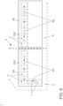
Fig. 1 und 2 Bezug genommen. In den Figuren ist ein Lichtmodul 1 in Explosionsdarstellung ersichtlich, welches ein rahmenartiges Bauteil 10, einen darin aufgenommenen, flächigen Lichtkörper 30 und eine Platine 50 mit Leuchtmitteln 51 umfasst. Das rahmenartige Bauteil 10 weist einen rechteckförmigen Umriss auf, welcher durch Seitenwände 11, 12, 13 und 14 gebildet wird. Die Seitenwände 11 bis 14 sind durch eine Rückwand 16 einstückig miteinander verbunden. Der Rückwand 16 gegenüberliegend ist eine Öffnung 17 vorhanden, welche vorzugsweise nahezu dem Umriss des Bauteils 10 entspricht. - Die in der Figur untere Seitenwand 14 ist mit einer im Umriss rechteckförmigen Öffnung 15 versehen. Durch die Öffnung 15 kann der flächige Lichtkörper 30 in einer Einschubrichtung R in das rahmenartige Bauteil 10 hineingeschoben werden. Innen kann das Bauteil 10 zusätzlich nicht näher dargestellte Führungs- und/oder Haltemittel für den Lichtkörper 30 aufweisen.
- Der Lichtkörper 30 weist, wie das Bauteil 10, einen rechteckförmigen Umriss auf und ist flächig ausgebildet. Er weist eine Flächenerstreckung F auf, die in jeder Richtung um ein Mehrfaches größer ist als seine Dicke d.
- Die Abmessungen des Lichtkörpers 30 sind derart bemessen, dass er in seiner Montageposition das rahmenartige Bauteil 10 im Wesentlichen ausfüllt.
- Der Lichtkörper 30 weist Seitenflächen 31, 32, 33 und 34 auf. Diese Seitenflächen umgeben eine Lichtaustrittsfläche 35. Die Lichtaustrittsfläche 35 liegt einer rückseitigen Fläche 36 gegenüber. Die Abmessungen des rahmenartigen Bauteils 10 und des Lichtkörpers 30 sind vorzugsweise so gewählt, dass der Lichtkörper 30 nach dem Einschieben in das Bauteil 10 sicher in diesem gehalten wird. Alternativ ist auch eine nicht näher dargestellte Verrastung denkbar.
- Der Lichtkörper 30 ist als Lichtleiter ausgebildet und weist einen Transmissionsgrad (eine Lichtdurchlässigkeit) in einem Bereich von etwa 85 Prozent bis etwa 95 Prozent auf. Besonders bevorzugt beträgt der Transmissionsgrad in etwa 92 Prozent.
- Die nur leichte Streueigenschaft des Lichtkörpers 30 wird durch lichtstreuende Störstellen 38 verursacht, die verteilt im Lichtkörper 30 angeordnet sind. Die lichtstreuenden Störstellen 38 können bei der Herstellung als Störpartikel in den Lichtkörper 30 eingebracht worden sein. Es ist alternativ auch denkbar die lichtstreuenden Störstellen über eine Laserbearbeitung in den Lichtkörper 30 einzubringen.
- Das rahmenartige Bauteil 10 ist innen reflektierend oder diffus rückstreuend ausgebildet.
- Hierzu kann eine innenliegende Oberfläche 16a der Rückwand 16 reflektierend oder diffus streuend ausgebildet sein. Dies kann beispielsweise durch eine weiße oder auch rote Beschichtung realisiert werden. In gleicher Weise kann eine innenliegende Oberfläche 11a der Seitenwand 11 ausgebildet sein.
- Die Farbe der außenliegenden Oberflächen des rahmenartigen Bauteils 10 ist vorzugsweise lichtdicht ausgebildet. Sie kann beispielsweise schwarz sein. Andere Farben sind denkbar.
- Die bereits erwähnte Platine 50 mit den als Leuchtdioden (LEDs) ausgebildeten Leuchtmitteln 51 ist in einem dichten Abstand b unterhalb der Seitenwand 14 angeordnet.
- Der Abstand b beträgt vorzugsweise in etwa 10 Millimeter. Des Weiteren ist ersichtlich, dass die Leuchtmittel 51 einen gegenseitigen Abstand a aufweisen, der im Ausführungsbeispiel bevorzugt bei etwa 5 Millimeter liegt.
- Der Lichtkörper 30 ist bevorzugt rot eingefärbt. Er kann beispielsweise aus PMMA (Polymethylmethacrylat) oder auch aus PC (Polycarbonat) bestehen.
- Die Ausbildung des Bauteils 10 und des Lichtkörpers 30 führen dazu, dass über die Leuchtmittel 51 in den Lichtkörper 30 eingekoppelte Lichtstrahlen L an den lichtstreuenden Störstellen 38 "hängen bleiben" beziehungsweise diffus gestreut werden. Dies trägt zu einer homogenen Ausleuchtung des Lichtkörpers 38 bei.
- Lichtstrahlen L, welche auf die innenliegenden Oberflächen 16a oder 11a auftreffen, werden in Richtung des Lichtkörpers 30 zurückreflektiert beziehungsweise diffus rückgestreut. Hierdurch wird ein wesentlicher Beitrag zur Erzielung einer homogenen Lichtabstrahlung des Lichtmoduls 1 geleistet. Allerdings wird durch die besagten Störstellen 38 dieser Effekt noch optimiert.
- Anhand der
Fig. 3 ist nun ersichtlich, wie das Lichtmodul 1 bevorzugt montiert sein kann. So sind auf der Platine 50 winkelartige Halterungen 53 vorhanden, welche mit der Platine 50 verbunden, vorzugsweise verschraubt oder verklebt sind. - Das rahmenartige Bauteil 10 weist an seinen gegenüberliegenden Seitenwänden 12, 13 jeweils hervorstehende Rastmittel 18 auf. Die Rastmittel 18 greifen rastend in Gegenrastmittel 52 der federnd auslenkbaren Halterungen 53 ein.
- Des Weiteren sind zwischen der unteren Seitenwandung 14 des Bauteils 10 und den Leuchtmitteln 51 jeweils Sammeloptiken 60 gestrichelt angedeutet. Diese sind optional und tragen dazu bei, dass von den Leuchtmitteln 51 ausgesendete Lichtstrahlen L "eingesammelt" und in Richtung des Lichtkörpers 30 ausgerichtet werden.
- Der
Fig. 4 ist eine Lichteinheit 100 zu entnehmen, welche aus drei Lichtmodulen (wie beschrieben) besteht. - So sind zum einen drei rahmenartige Bauteile 10 vorhanden, welche jeweils über ein stegartiges Verbindungselement 19 einstückig miteinander verbunden sind. Auf der anderen Seite sind drei Lichtkörper 30 jeweils über ein stegartiges Verbindungselement 37 einstückig miteinander verbunden.
- Die Bauteile 10, wie auch die Lichtkörper 30, können also auf einfache Weise in einem Arbeitsgang, vorzugsweise jeweils in einem Spritzgusswerkzeug hergestellt werden.
- Zur Erleichterung der Montage weist jedes der Verbindungselemente 19 im Querschnitt eine gewölbte Form auf, so dass ein halbkreisartiger Aufnahmeraum 19a geschaffen wird. Der Aufnahmeraum 19a seinerseits dient bei der Montage zur Aufnahme des im Querschnitt halbkreisartig ausgebildeten Verbindungselementes 37 (vergleiche
Fig. 5 ). - Schließlich ist eine Platine 50' vorhanden, welche entsprechend länger ausgebildet ist als die Platine 50 (vgl.
Fig. 1 ) und jeweils mehrere, vorzugsweise drei Leuchtmittel 51 aufnimmt, die den Lichtkörpern 30 jeweils zugeordnet sind. - Anhand der
Fig. 6 ist dargestellt, dass die Lichtmodule 1 oder aus diesen bestehende Lichteinheiten 100' beziehungsweise 100" auch in einer Beleuchtungsvorrichtung 2 eines gestrichelt angedeuteten Kraftfahrzeugs verwendet werden können. Die Beleuchtungsvorrichtung 2 kann eine Heckbeleuchtung eines Kraftfahrzeugs sein, wobei ein karosserieseitiger Teil 2a der Beleuchtungsvorrichtung 2 in eine Karosserie 3 und ein heckklappenseitiger Teil 2b der Beleuchtungsvorrichtung 2 in eine Heckklappe 4 eines Kraftfahrzeugs eingebaut werden kann. - Über eine hier nicht näher dargestellte Steuereinheit ist es denkbar, die einzelnen Lichtmodule 1 nacheinander derart anzusteuern, dass lichttechnische Animationen A1 beziehungsweise A2 (vergleichen Pfeilrichtung) erzeugt werden. Dies ist beispielsweise zur Realisierung einer sogenannten Coming-Home- oder Leaving-Home-Funktion denkbar.
- Schließlich zeigt die
Fig. 7 ein Kraftfahrzeug K, in welchem zwei als Heckleuchten dienende Beleuchtungsvorrichtungen 2 verbaut sind. Eine Steuereinheit 5 dient über Signal- und Steuerleitungen S zur Ansteuerung der Beleuchtungsvorrichtungen 2. -
- 1
- Lichtmodul
- 2
- Beleuchtungsvorrichtung
- 2a
- karosserieseitiger Teil der Beleuchtungsvorrichtung
- 2b
- heckklappenseitiger Teil der Beleuchtungsvorrichtung
- 3
- Karosserie
- 4
- Heckklappe
- 5
- Steuereinheit
- 10
- Abdeckung, rahmenartiges Bauteil
- 11
- Seitenwand
- 11a
- innenliegende Oberfläche
- 12
- Seitenwand
- 13
- Seitenwand
- 14
- Seitenwand
- 15
- Öffnung
- 16
- Rückwand
- 16a
- innenliegende Oberfläche
- 17
- Öffnung
- 18
- Rastmittel
- 19
- stegartiges Verbindungselement
- 19a
- Aufnahmeraum
- 30
- flächiger Lichtkörper
- 31
- Seitenfläche
- 32
- Seitenfläche
- 33
- Seitenfläche
- 34
- Seitenfläche
- 35
- Lichtaustrittsfläche
- 36
- rückseitige Fläche
- 37
- stegartiges Verbindungselement
- 38
- lichtstreuende Störstellen
- 50, 50'
- Platine
- 51
- Leuchtmittel, LEDs
- 52
- Gegenrastmittel
- 53
- Halterung
- 60
- Sammeloptik
- 100, 100', 100"
- Lichteinheiten
- a
- Abstand
- A1, A2
- Animationen
- b
- Abstand
- d
- Dicke
- F
- Flächenerstreckung
- L
- Lichtstrahlen
- R
- Einschubrichtung
- S
- Signal- und Steuerleitung
Claims (10)
- Lichteinheit (100, 100', 100") zur Verwendung in einer Beleuchtungsvorrichtung (2; 2a, 2b) für ein Kraftfahrzeug (K), mit wenigstens einem Lichtmodul (1) mit einem flächigen, als Lichtleiter ausgebildeten Lichtkörper (30) und wenigstens einem Leuchtmittel (51), dessen Lichtstrahlen (L) in eine Seitenfläche (34) des Lichtkörpers (30) einkoppelbar sind oder eingekoppelt werden, wobei die Lichtstrahlen (L) über eine von Seitenflächen (31-34) des Lichtkörpers (30) umgebene Lichtaustrittsfläche (35) nach außen austreten können oder austreten und wobei zumindest ein Teil der Seitenflächen (31-34) und eine der Lichtaustrittsfläche (35) gegenüberliegende, rückseitige Fläche (36) durch eine reflektierende oder diffus rückstreuende Abdeckung (10) abgedeckt wird, wobei die Abdeckung (10) des einen Lichtkörpers (30) durch ein rahmenartiges Bauteil (10) mit einer Rückwand (16) und einer der Rückwand (16) gegenüberliegenden Öffnung (17) gebildet wird, wobei die Abmessungen des Lichtkörpers (30) derart bemessen sind, dass er in seiner Montageposition das rahmenartige Bauteil (10) im Wesentlichen ausfüllt, dadurch gekennzeichnet, dass eine Seitenwand (14) des rahmenartiges Bauteils (10) eine Öffnung (15) aufweist, durch die der Lichtkörper (30) in das rahmenartige Bauteil (10) seitlich eingebracht ist, wobei das wenigstens eine Leuchtmittel (51) an der die Öffnung (15) aufweisenden Seitenwand (14) des rahmenartigen Bauteils (10) angeordnet ist, wobei der Lichtkörper (30) einen Transmissionsgrad in einem Bereich von etwa 85 % bis etwa 95 % aufweist und wobei die Lichteinheit (100, 100', 100") aus mehreren Lichtmodulen (1) gebildet ist, bei der die rahmenartigen Bauteile (10) einerseits und die flächigen Lichtkörper (30) andererseits jeweils einstückig miteinander verbunden sind und wobei die rahmenartige Bauteile (10) auf einer gemeinsamen Platine (50') befestigt sind, die die den flächigen Lichtkörpern (30) zugeordneten Leuchtmittel (51) trägt.
- Lichteinheit (100, 100', 100") nach Anspruch 1, dadurch gekennzeichnet, dass im jeden Lichtkörper (30) verteilt lichtstreuende Störstellen (38) angeordnet sind
- Lichteinheit (100, 100', 100") nach Anspruch 2, dadurch gekennzeichnet, dass jeder Lichtkörper (30) einen Transmissionsgrad von etwa 92% aufweist.
- Lichteinheit (100, 100', 100") nach einem der vorhergehenden Ansprüche, dadurch gekennzeichnet, dass jedes von wenigstens einem Leuchtmittel (51) in einem Abstand (b) von der Seitenwand (14) angeordnet ist.
- Lichteinheit (100, 100', 100") nach einem der vorhergehenden Ansprüche, dadurch gekennzeichnet, dass jeweils zwischen dem wenigstens einen Leuchtmittel (51) und der Seitenwand (14) wenigstens eine Sammeloptik (60) angeordnet ist.
- Lichteinheit (100, 100', 100") nach einem der vorhergehenden Ansprüche, dadurch gekennzeichnet, dass jeweiliges rahmenartige Bauteil (10) über eine Halterung (53) auf der Platine (50,50') befestigt ist, welche auch jedes von wenigstens einem Leuchtmittel (51) trägt.
- Lichteinheit (100, 100', 100") nach Anspruch 6, dadurch gekennzeichnet, dass jeweils das rahmenartige Bauteil (10) mit der Halterung (53) verrastet ist.
- Lichteinheit (100, 100', 100") nach einem der vorhergehenden Ansprüche, dadurch gekennzeichnet, dass jeweils mehrere als Leuchtdioden ausgebildete Leuchtmittel (51) vorhanden sind, welche einen gegenseitigen Abstand (a) zueinander von mehr als 4,5 mm und weniger als 6,5 mm aufweisen.
- Beleuchtungsvorrichtung (2; 2a, 2b) für ein Kraftfahrzeug (K), gekennzeichnet durch wenigstens eine Lichteinheit (100, 100', 100") nach einem der Ansprüche 1 bis 8.
- Kraftfahrzeug, gekennzeichnet durch wenigstens eine Beleuchtungsvorrichtung (2; 2a, 2b) nach Anspruch 9.
Applications Claiming Priority (2)
| Application Number | Priority Date | Filing Date | Title |
|---|---|---|---|
| DE102018215988.2A DE102018215988A1 (de) | 2018-09-19 | 2018-09-19 | Lichtmodul, insbesondere zur Verwendung in einer Beleuchtungsvorrichtung für ein Kraftfahrzeug |
| PCT/EP2019/074788 WO2020058236A1 (de) | 2018-09-19 | 2019-09-17 | Lichtmodul, insbesondere zur verwendung in einer beleuchtungsvorrichtung für ein kraftfahrzeug |
Publications (3)
| Publication Number | Publication Date |
|---|---|
| EP3853518A1 EP3853518A1 (de) | 2021-07-28 |
| EP3853518C0 EP3853518C0 (de) | 2023-11-29 |
| EP3853518B1 true EP3853518B1 (de) | 2023-11-29 |
Family
ID=68062901
Family Applications (1)
| Application Number | Title | Priority Date | Filing Date |
|---|---|---|---|
| EP19773759.6A Active EP3853518B1 (de) | 2018-09-19 | 2019-09-17 | Lichtmodul, insbesondere zur verwendung in einer beleuchtungsvorrichtung für ein kraftfahrzeug |
Country Status (6)
| Country | Link |
|---|---|
| US (1) | US11408580B2 (de) |
| EP (1) | EP3853518B1 (de) |
| CN (1) | CN112739951B (de) |
| DE (1) | DE102018215988A1 (de) |
| ES (1) | ES2971107T3 (de) |
| WO (1) | WO2020058236A1 (de) |
Families Citing this family (2)
| Publication number | Priority date | Publication date | Assignee | Title |
|---|---|---|---|---|
| DE102020208105B4 (de) | 2020-06-30 | 2025-02-06 | Volkswagen Aktiengesellschaft | Kraftfahrzeug mit wenigstens einer Beleuchtungsvorrichtung im Bereich einer Klappe sowie Teil einer Beleuchtungsvorrichtung für ein Kraftfahrzeug |
| CN218954705U (zh) * | 2022-11-25 | 2023-05-02 | 法雷奥市光(中国)车灯有限公司 | 光学照射组件、照明设备以及机动车辆 |
Family Cites Families (30)
| Publication number | Priority date | Publication date | Assignee | Title |
|---|---|---|---|---|
| US5150960A (en) * | 1991-12-06 | 1992-09-29 | General Motors Corporation | Rear license plate illumination |
| US6428175B1 (en) | 1998-09-14 | 2002-08-06 | Dr.-Ing. Willing Gmbh | Advisory lighting fitting |
| DE19902774A1 (de) | 1999-01-25 | 2000-08-10 | Willing Gmbh Dr Ing | Leuchtkörper mit Leuchtdioden für Selbstleuchter und zur Hinterleuchtung von Hinweiselementen |
| DE19860697A1 (de) | 1998-12-29 | 2000-08-10 | Osram Opto Semiconductors Gmbh | Verfahren zur Herstellung eines flachen Lichtleitermoduls |
| ATE340967T1 (de) | 1998-12-29 | 2006-10-15 | Osram Opto Semiconductors Gmbh | Lichtquellenelement mit seitlicher schräger lichteinkopplung |
| DE10238073A1 (de) * | 2002-08-21 | 2004-03-04 | Hella Kg Hueck & Co. | Fahrzeugleuchte |
| US7156534B2 (en) * | 2004-03-03 | 2007-01-02 | Coretronic Corporation | Backlight module |
| JP4780788B2 (ja) * | 2007-01-31 | 2011-09-28 | スタンレー電気株式会社 | Led灯具ユニット |
| KR101385204B1 (ko) * | 2007-05-25 | 2014-04-14 | 삼성디스플레이 주식회사 | 백라이트 어셈블리 및 이를 구비한 액정표시장치 |
| US8089582B2 (en) * | 2007-05-31 | 2012-01-03 | Hitachi Displays, Ltd. | Liquid crystal display device comprising at least one groove having an end portion that stops short of the non-adjacent opposite side surfaces and extends in a direction perpendicular to the non-adjacent side surfaces |
| KR20090073886A (ko) * | 2007-12-31 | 2009-07-03 | 엘지디스플레이 주식회사 | 액정표시장치 |
| DE102009053581B3 (de) * | 2009-10-05 | 2011-03-03 | Automotive Lighting Reutlingen Gmbh | Lichtmodul für eine Beleuchtungseinrichtung eines Kraftfahrzeugs |
| US20120257107A1 (en) * | 2009-12-28 | 2012-10-11 | Sharp Kabushiki Kaisha | Illumination device, liquid crystal display device and television receiver device |
| JP5440857B2 (ja) * | 2010-03-05 | 2014-03-12 | スタンレー電気株式会社 | 車両用灯具ユニット、及び、車両用灯具 |
| KR101719693B1 (ko) * | 2010-05-11 | 2017-03-27 | 삼성디스플레이 주식회사 | 발광 다이오드 패키지 및 이를 포함하는 표시 장치 |
| EP2428724B1 (de) | 2010-09-08 | 2017-03-29 | SMR Patents S.à.r.l. | Optimale Lichteinkopplung für Rückblickeinrichtungen |
| DE102011110629B4 (de) | 2011-08-18 | 2025-04-03 | Volkswagen Aktiengesellschaft | Beleuchtungsvorrichtung |
| DE102011110630A1 (de) | 2011-08-18 | 2013-02-21 | Volkswagen Aktiengesellschaft | Verfahren zur Ansteuerung von Leuchtmitteln einer Beleuchtungseinrichtung für ein Kraftzeug und Beleuchtungseinrichtung |
| JP2013058396A (ja) | 2011-09-08 | 2013-03-28 | Koito Mfg Co Ltd | 車両用灯具 |
| WO2013188678A1 (en) | 2012-06-13 | 2013-12-19 | Innotec, Corp. | Flexible light pipe |
| ITTV20130190A1 (it) * | 2013-11-20 | 2015-05-21 | Automotive Lighting Italia Spa | Fanale automobilistico |
| DE102014110225A1 (de) * | 2014-07-21 | 2016-01-21 | Osram Opto Semiconductors Gmbh | Fahrzeugleuchte |
| KR102305599B1 (ko) | 2014-10-22 | 2021-09-28 | 엘지이노텍 주식회사 | 조명장치 및 이를 포함하는 차량용 램프 |
| JP6514912B2 (ja) * | 2015-02-26 | 2019-05-15 | 株式会社村上開明堂 | ターンランプ |
| KR101702589B1 (ko) * | 2015-11-30 | 2017-02-03 | 엘지디스플레이 주식회사 | 홀을 구비한 이형 디스플레이 |
| KR20170064664A (ko) * | 2015-12-02 | 2017-06-12 | 엘지이노텍 주식회사 | 조명장치 및 이를 포함하는 차량용 램프 |
| KR101873279B1 (ko) * | 2016-06-10 | 2018-07-03 | (주)미경테크 | 백라이트 유닛 및 이의 제조 방법 |
| WO2019037803A1 (en) * | 2017-08-22 | 2019-02-28 | Varroc Lighting Systems, s.r.o. | LUMINOUS DEVICE OF A MOTOR VEHICLE |
| CZ2017773A3 (cs) * | 2017-12-01 | 2019-06-12 | Varroc Lighting Systems, s.r.o. | Světelné zařízení, zejména signální svítilna, pro motorová vozidla |
| KR102564889B1 (ko) * | 2018-02-08 | 2023-08-09 | 주식회사 아모센스 | 자동차의 리어 램프 모듈 및 이를 갖는 리어 콤비네이션 램프 |
-
2018
- 2018-09-19 DE DE102018215988.2A patent/DE102018215988A1/de not_active Withdrawn
-
2019
- 2019-09-17 US US17/277,851 patent/US11408580B2/en active Active
- 2019-09-17 EP EP19773759.6A patent/EP3853518B1/de active Active
- 2019-09-17 WO PCT/EP2019/074788 patent/WO2020058236A1/de not_active Ceased
- 2019-09-17 CN CN201980060882.1A patent/CN112739951B/zh active Active
- 2019-09-17 ES ES19773759T patent/ES2971107T3/es active Active
Also Published As
| Publication number | Publication date |
|---|---|
| CN112739951B (zh) | 2023-04-25 |
| EP3853518C0 (de) | 2023-11-29 |
| WO2020058236A1 (de) | 2020-03-26 |
| CN112739951A (zh) | 2021-04-30 |
| US11408580B2 (en) | 2022-08-09 |
| DE102018215988A1 (de) | 2020-03-19 |
| US20210348737A1 (en) | 2021-11-11 |
| EP3853518A1 (de) | 2021-07-28 |
| ES2971107T3 (es) | 2024-06-03 |
Similar Documents
| Publication | Publication Date | Title |
|---|---|---|
| EP2816276B1 (de) | Kraftfahrzeug mit einer Leuchtvorrichtung | |
| EP3141797B1 (de) | Linienleuchte | |
| DE102004054732B4 (de) | Lichtleiteranordung | |
| WO2018149741A1 (de) | Beleuchtungsvorrichtung für ein innenausstattungsteil | |
| DE102020207459A1 (de) | Beleuchtungsvorrichtung für ein Kraftfahrzeug | |
| EP3844028A1 (de) | Beleuchtungsvorrichtung für ein kraftfahrzeug | |
| DE102012103310A1 (de) | Beleuchtungsvorrichtung für Fahrzeuge | |
| WO2000039501A1 (de) | Lichtquellenelement mit seitlicher schräger lichteinkopplung | |
| DE102008056985A1 (de) | Zierleuchteneinheit für Fahrzeuge | |
| WO2013029730A1 (de) | Leuchteinrichtung für ein fahrzeug mit einer mehrschichtigen lichtscheibe | |
| DE102006035842B9 (de) | Fahrzeugleuchte mit einer einstückigen Lichtleiter-Blenden-Einheit | |
| DE102013007856A1 (de) | Lichtleitkörper und Leuchtvorrichtung mit dem Lichtleitkörper | |
| EP1818698A1 (de) | Beleuchtungseinrichtung für ein reflektierendes Schild, beleuchtete Schildanordnung sowie Halter | |
| EP3158260B1 (de) | Kraftfahrzeugbeleuchtungseinrichtung | |
| DE102005019018A1 (de) | Leuchte mit wenigstens einem Lichtleiter und mehreren Lichtquellen | |
| EP4166843A1 (de) | Beleuchtungsvorrichtung für ein kraftfahrzeug | |
| DE202005014267U1 (de) | Fahrzeugleuchte mit einem Lichtleiter mit zentraler Lichteinkopplung | |
| DE112016001066T5 (de) | Hoch montierte bremsleuchte für ein automobil | |
| DE102018202127A1 (de) | Beleuchtungsvorrichtung zur Erzeugung eines Ambientelichts im Innenraum eines Kraftfahrzeugs | |
| DE102014102355A1 (de) | Beleuchtungsvorrichtung für Fahrzeuge | |
| EP3853518A1 (de) | Lichtmodul, insbesondere zur verwendung in einer beleuchtungsvorrichtung für ein kraftfahrzeug | |
| DE102020201645A1 (de) | Beleuchtungsvorrichtung für ein Kraftfahrzeug | |
| DE102021117619A1 (de) | Beleuchtungsvorrichtung für den Außenraum eines Kraftfahrzeugs | |
| DE102010050955A1 (de) | Beleuchtungsvorrichtung für Fahrzeuge | |
| DE102020201648A1 (de) | Beleuchtungsvorrichtung für ein Kraftfahrzeug |
Legal Events
| Date | Code | Title | Description |
|---|---|---|---|
| STAA | Information on the status of an ep patent application or granted ep patent |
Free format text: STATUS: UNKNOWN |
|
| STAA | Information on the status of an ep patent application or granted ep patent |
Free format text: STATUS: THE INTERNATIONAL PUBLICATION HAS BEEN MADE |
|
| PUAI | Public reference made under article 153(3) epc to a published international application that has entered the european phase |
Free format text: ORIGINAL CODE: 0009012 |
|
| STAA | Information on the status of an ep patent application or granted ep patent |
Free format text: STATUS: REQUEST FOR EXAMINATION WAS MADE |
|
| 17P | Request for examination filed |
Effective date: 20210419 |
|
| AK | Designated contracting states |
Kind code of ref document: A1 Designated state(s): AL AT BE BG CH CY CZ DE DK EE ES FI FR GB GR HR HU IE IS IT LI LT LU LV MC MK MT NL NO PL PT RO RS SE SI SK SM TR |
|
| DAV | Request for validation of the european patent (deleted) | ||
| DAX | Request for extension of the european patent (deleted) | ||
| STAA | Information on the status of an ep patent application or granted ep patent |
Free format text: STATUS: EXAMINATION IS IN PROGRESS |
|
| 17Q | First examination report despatched |
Effective date: 20230214 |
|
| GRAP | Despatch of communication of intention to grant a patent |
Free format text: ORIGINAL CODE: EPIDOSNIGR1 |
|
| STAA | Information on the status of an ep patent application or granted ep patent |
Free format text: STATUS: GRANT OF PATENT IS INTENDED |
|
| INTG | Intention to grant announced |
Effective date: 20230623 |
|
| GRAS | Grant fee paid |
Free format text: ORIGINAL CODE: EPIDOSNIGR3 |
|
| GRAA | (expected) grant |
Free format text: ORIGINAL CODE: 0009210 |
|
| STAA | Information on the status of an ep patent application or granted ep patent |
Free format text: STATUS: THE PATENT HAS BEEN GRANTED |
|
| AK | Designated contracting states |
Kind code of ref document: B1 Designated state(s): AL AT BE BG CH CY CZ DE DK EE ES FI FR GB GR HR HU IE IS IT LI LT LU LV MC MK MT NL NO PL PT RO RS SE SI SK SM TR |
|
| REG | Reference to a national code |
Ref country code: GB Ref legal event code: FG4D Free format text: NOT ENGLISH |
|
| REG | Reference to a national code |
Ref country code: CH Ref legal event code: EP |
|
| REG | Reference to a national code |
Ref country code: DE Ref legal event code: R096 Ref document number: 502019010039 Country of ref document: DE |
|
| REG | Reference to a national code |
Ref country code: IE Ref legal event code: FG4D Free format text: LANGUAGE OF EP DOCUMENT: GERMAN |
|
| U01 | Request for unitary effect filed |
Effective date: 20231213 |
|
| U07 | Unitary effect registered |
Designated state(s): AT BE BG DE DK EE FI FR IT LT LU LV MT NL PT SE SI Effective date: 20231219 |
|
| PG25 | Lapsed in a contracting state [announced via postgrant information from national office to epo] |
Ref country code: GR Free format text: LAPSE BECAUSE OF FAILURE TO SUBMIT A TRANSLATION OF THE DESCRIPTION OR TO PAY THE FEE WITHIN THE PRESCRIBED TIME-LIMIT Effective date: 20240301 |
|
| PG25 | Lapsed in a contracting state [announced via postgrant information from national office to epo] |
Ref country code: IS Free format text: LAPSE BECAUSE OF FAILURE TO SUBMIT A TRANSLATION OF THE DESCRIPTION OR TO PAY THE FEE WITHIN THE PRESCRIBED TIME-LIMIT Effective date: 20240329 |
|
| PG25 | Lapsed in a contracting state [announced via postgrant information from national office to epo] |
Ref country code: IS Free format text: LAPSE BECAUSE OF FAILURE TO SUBMIT A TRANSLATION OF THE DESCRIPTION OR TO PAY THE FEE WITHIN THE PRESCRIBED TIME-LIMIT Effective date: 20240329 Ref country code: GR Free format text: LAPSE BECAUSE OF FAILURE TO SUBMIT A TRANSLATION OF THE DESCRIPTION OR TO PAY THE FEE WITHIN THE PRESCRIBED TIME-LIMIT Effective date: 20240301 |
|
| PG25 | Lapsed in a contracting state [announced via postgrant information from national office to epo] |
Ref country code: RS Free format text: LAPSE BECAUSE OF FAILURE TO SUBMIT A TRANSLATION OF THE DESCRIPTION OR TO PAY THE FEE WITHIN THE PRESCRIBED TIME-LIMIT Effective date: 20231129 Ref country code: PL Free format text: LAPSE BECAUSE OF FAILURE TO SUBMIT A TRANSLATION OF THE DESCRIPTION OR TO PAY THE FEE WITHIN THE PRESCRIBED TIME-LIMIT Effective date: 20231129 Ref country code: NO Free format text: LAPSE BECAUSE OF FAILURE TO SUBMIT A TRANSLATION OF THE DESCRIPTION OR TO PAY THE FEE WITHIN THE PRESCRIBED TIME-LIMIT Effective date: 20240229 Ref country code: HR Free format text: LAPSE BECAUSE OF FAILURE TO SUBMIT A TRANSLATION OF THE DESCRIPTION OR TO PAY THE FEE WITHIN THE PRESCRIBED TIME-LIMIT Effective date: 20231129 |
|
| REG | Reference to a national code |
Ref country code: ES Ref legal event code: FG2A Ref document number: 2971107 Country of ref document: ES Kind code of ref document: T3 Effective date: 20240603 |
|
| PG25 | Lapsed in a contracting state [announced via postgrant information from national office to epo] |
Ref country code: CZ Free format text: LAPSE BECAUSE OF FAILURE TO SUBMIT A TRANSLATION OF THE DESCRIPTION OR TO PAY THE FEE WITHIN THE PRESCRIBED TIME-LIMIT Effective date: 20231129 |
|
| PG25 | Lapsed in a contracting state [announced via postgrant information from national office to epo] |
Ref country code: SK Free format text: LAPSE BECAUSE OF FAILURE TO SUBMIT A TRANSLATION OF THE DESCRIPTION OR TO PAY THE FEE WITHIN THE PRESCRIBED TIME-LIMIT Effective date: 20231129 |
|
| PG25 | Lapsed in a contracting state [announced via postgrant information from national office to epo] |
Ref country code: SM Free format text: LAPSE BECAUSE OF FAILURE TO SUBMIT A TRANSLATION OF THE DESCRIPTION OR TO PAY THE FEE WITHIN THE PRESCRIBED TIME-LIMIT Effective date: 20231129 Ref country code: SK Free format text: LAPSE BECAUSE OF FAILURE TO SUBMIT A TRANSLATION OF THE DESCRIPTION OR TO PAY THE FEE WITHIN THE PRESCRIBED TIME-LIMIT Effective date: 20231129 Ref country code: RO Free format text: LAPSE BECAUSE OF FAILURE TO SUBMIT A TRANSLATION OF THE DESCRIPTION OR TO PAY THE FEE WITHIN THE PRESCRIBED TIME-LIMIT Effective date: 20231129 Ref country code: CZ Free format text: LAPSE BECAUSE OF FAILURE TO SUBMIT A TRANSLATION OF THE DESCRIPTION OR TO PAY THE FEE WITHIN THE PRESCRIBED TIME-LIMIT Effective date: 20231129 |
|
| REG | Reference to a national code |
Ref country code: DE Ref legal event code: R097 Ref document number: 502019010039 Country of ref document: DE |
|
| PLBE | No opposition filed within time limit |
Free format text: ORIGINAL CODE: 0009261 |
|
| STAA | Information on the status of an ep patent application or granted ep patent |
Free format text: STATUS: NO OPPOSITION FILED WITHIN TIME LIMIT |
|
| U20 | Renewal fee for the european patent with unitary effect paid |
Year of fee payment: 6 Effective date: 20240926 |
|
| 26N | No opposition filed |
Effective date: 20240830 |
|
| PG25 | Lapsed in a contracting state [announced via postgrant information from national office to epo] |
Ref country code: MC Free format text: LAPSE BECAUSE OF FAILURE TO SUBMIT A TRANSLATION OF THE DESCRIPTION OR TO PAY THE FEE WITHIN THE PRESCRIBED TIME-LIMIT Effective date: 20231129 |
|
| REG | Reference to a national code |
Ref country code: CH Ref legal event code: PL |
|
| PG25 | Lapsed in a contracting state [announced via postgrant information from national office to epo] |
Ref country code: CH Free format text: LAPSE BECAUSE OF NON-PAYMENT OF DUE FEES Effective date: 20240930 |
|
| PG25 | Lapsed in a contracting state [announced via postgrant information from national office to epo] |
Ref country code: IE Free format text: LAPSE BECAUSE OF NON-PAYMENT OF DUE FEES Effective date: 20240917 |
|
| PGFP | Annual fee paid to national office [announced via postgrant information from national office to epo] |
Ref country code: GB Payment date: 20250923 Year of fee payment: 7 |
|
| U20 | Renewal fee for the european patent with unitary effect paid |
Year of fee payment: 7 Effective date: 20250925 |
|
| PG25 | Lapsed in a contracting state [announced via postgrant information from national office to epo] |
Ref country code: CY Free format text: LAPSE BECAUSE OF FAILURE TO SUBMIT A TRANSLATION OF THE DESCRIPTION OR TO PAY THE FEE WITHIN THE PRESCRIBED TIME-LIMIT; INVALID AB INITIO Effective date: 20190917 |
|
| PGFP | Annual fee paid to national office [announced via postgrant information from national office to epo] |
Ref country code: ES Payment date: 20251008 Year of fee payment: 7 |
|
| PG25 | Lapsed in a contracting state [announced via postgrant information from national office to epo] |
Ref country code: HU Free format text: LAPSE BECAUSE OF FAILURE TO SUBMIT A TRANSLATION OF THE DESCRIPTION OR TO PAY THE FEE WITHIN THE PRESCRIBED TIME-LIMIT; INVALID AB INITIO Effective date: 20190917 |