EP3853518B1 - Module d'éclairage, notamment destiné à être utilisé dans un dispositif d'éclairage pour véhicule automobile - Google Patents
Module d'éclairage, notamment destiné à être utilisé dans un dispositif d'éclairage pour véhicule automobile Download PDFInfo
- Publication number
- EP3853518B1 EP3853518B1 EP19773759.6A EP19773759A EP3853518B1 EP 3853518 B1 EP3853518 B1 EP 3853518B1 EP 19773759 A EP19773759 A EP 19773759A EP 3853518 B1 EP3853518 B1 EP 3853518B1
- Authority
- EP
- European Patent Office
- Prior art keywords
- light
- frame
- unit
- emitting means
- type component
- Prior art date
- Legal status (The legal status is an assumption and is not a legal conclusion. Google has not performed a legal analysis and makes no representation as to the accuracy of the status listed.)
- Active
Links
Images


Classifications
-
- F—MECHANICAL ENGINEERING; LIGHTING; HEATING; WEAPONS; BLASTING
- F21—LIGHTING
- F21S—NON-PORTABLE LIGHTING DEVICES; SYSTEMS THEREOF; VEHICLE LIGHTING DEVICES SPECIALLY ADAPTED FOR VEHICLE EXTERIORS
- F21S43/00—Signalling devices specially adapted for vehicle exteriors, e.g. brake lamps, direction indicator lights or reversing lights
- F21S43/10—Signalling devices specially adapted for vehicle exteriors, e.g. brake lamps, direction indicator lights or reversing lights characterised by the light source
- F21S43/13—Signalling devices specially adapted for vehicle exteriors, e.g. brake lamps, direction indicator lights or reversing lights characterised by the light source characterised by the type of light source
- F21S43/14—Light emitting diodes [LED]
-
- F—MECHANICAL ENGINEERING; LIGHTING; HEATING; WEAPONS; BLASTING
- F21—LIGHTING
- F21S—NON-PORTABLE LIGHTING DEVICES; SYSTEMS THEREOF; VEHICLE LIGHTING DEVICES SPECIALLY ADAPTED FOR VEHICLE EXTERIORS
- F21S43/00—Signalling devices specially adapted for vehicle exteriors, e.g. brake lamps, direction indicator lights or reversing lights
- F21S43/40—Signalling devices specially adapted for vehicle exteriors, e.g. brake lamps, direction indicator lights or reversing lights characterised by the combination of reflectors and refractors
- F21S43/402—Total internal reflection [TIR] collimators
-
- F—MECHANICAL ENGINEERING; LIGHTING; HEATING; WEAPONS; BLASTING
- F21—LIGHTING
- F21S—NON-PORTABLE LIGHTING DEVICES; SYSTEMS THEREOF; VEHICLE LIGHTING DEVICES SPECIALLY ADAPTED FOR VEHICLE EXTERIORS
- F21S43/00—Signalling devices specially adapted for vehicle exteriors, e.g. brake lamps, direction indicator lights or reversing lights
- F21S43/10—Signalling devices specially adapted for vehicle exteriors, e.g. brake lamps, direction indicator lights or reversing lights characterised by the light source
- F21S43/13—Signalling devices specially adapted for vehicle exteriors, e.g. brake lamps, direction indicator lights or reversing lights characterised by the light source characterised by the type of light source
- F21S43/15—Strips of light sources
-
- F—MECHANICAL ENGINEERING; LIGHTING; HEATING; WEAPONS; BLASTING
- F21—LIGHTING
- F21S—NON-PORTABLE LIGHTING DEVICES; SYSTEMS THEREOF; VEHICLE LIGHTING DEVICES SPECIALLY ADAPTED FOR VEHICLE EXTERIORS
- F21S43/00—Signalling devices specially adapted for vehicle exteriors, e.g. brake lamps, direction indicator lights or reversing lights
- F21S43/10—Signalling devices specially adapted for vehicle exteriors, e.g. brake lamps, direction indicator lights or reversing lights characterised by the light source
- F21S43/19—Attachment of light sources or lamp holders
-
- F—MECHANICAL ENGINEERING; LIGHTING; HEATING; WEAPONS; BLASTING
- F21—LIGHTING
- F21S—NON-PORTABLE LIGHTING DEVICES; SYSTEMS THEREOF; VEHICLE LIGHTING DEVICES SPECIALLY ADAPTED FOR VEHICLE EXTERIORS
- F21S43/00—Signalling devices specially adapted for vehicle exteriors, e.g. brake lamps, direction indicator lights or reversing lights
- F21S43/20—Signalling devices specially adapted for vehicle exteriors, e.g. brake lamps, direction indicator lights or reversing lights characterised by refractors, transparent cover plates, light guides or filters
- F21S43/235—Light guides
- F21S43/236—Light guides characterised by the shape of the light guide
- F21S43/239—Light guides characterised by the shape of the light guide plate-shaped
-
- F—MECHANICAL ENGINEERING; LIGHTING; HEATING; WEAPONS; BLASTING
- F21—LIGHTING
- F21S—NON-PORTABLE LIGHTING DEVICES; SYSTEMS THEREOF; VEHICLE LIGHTING DEVICES SPECIALLY ADAPTED FOR VEHICLE EXTERIORS
- F21S43/00—Signalling devices specially adapted for vehicle exteriors, e.g. brake lamps, direction indicator lights or reversing lights
- F21S43/20—Signalling devices specially adapted for vehicle exteriors, e.g. brake lamps, direction indicator lights or reversing lights characterised by refractors, transparent cover plates, light guides or filters
- F21S43/235—Light guides
- F21S43/242—Light guides characterised by the emission area
- F21S43/245—Light guides characterised by the emission area emitting light from one or more of its major surfaces
-
- F—MECHANICAL ENGINEERING; LIGHTING; HEATING; WEAPONS; BLASTING
- F21—LIGHTING
- F21S—NON-PORTABLE LIGHTING DEVICES; SYSTEMS THEREOF; VEHICLE LIGHTING DEVICES SPECIALLY ADAPTED FOR VEHICLE EXTERIORS
- F21S43/00—Signalling devices specially adapted for vehicle exteriors, e.g. brake lamps, direction indicator lights or reversing lights
- F21S43/20—Signalling devices specially adapted for vehicle exteriors, e.g. brake lamps, direction indicator lights or reversing lights characterised by refractors, transparent cover plates, light guides or filters
- F21S43/235—Light guides
- F21S43/242—Light guides characterised by the emission area
- F21S43/246—Light guides characterised by the emission area having two or more output branches
-
- F—MECHANICAL ENGINEERING; LIGHTING; HEATING; WEAPONS; BLASTING
- F21—LIGHTING
- F21S—NON-PORTABLE LIGHTING DEVICES; SYSTEMS THEREOF; VEHICLE LIGHTING DEVICES SPECIALLY ADAPTED FOR VEHICLE EXTERIORS
- F21S43/00—Signalling devices specially adapted for vehicle exteriors, e.g. brake lamps, direction indicator lights or reversing lights
- F21S43/20—Signalling devices specially adapted for vehicle exteriors, e.g. brake lamps, direction indicator lights or reversing lights characterised by refractors, transparent cover plates, light guides or filters
- F21S43/235—Light guides
- F21S43/249—Light guides with two or more light sources being coupled into the light guide
- F21S43/2492—Light guides with two or more light sources being coupled into the light guide having two or more input branches
-
- F—MECHANICAL ENGINEERING; LIGHTING; HEATING; WEAPONS; BLASTING
- F21—LIGHTING
- F21S—NON-PORTABLE LIGHTING DEVICES; SYSTEMS THEREOF; VEHICLE LIGHTING DEVICES SPECIALLY ADAPTED FOR VEHICLE EXTERIORS
- F21S43/00—Signalling devices specially adapted for vehicle exteriors, e.g. brake lamps, direction indicator lights or reversing lights
- F21S43/20—Signalling devices specially adapted for vehicle exteriors, e.g. brake lamps, direction indicator lights or reversing lights characterised by refractors, transparent cover plates, light guides or filters
- F21S43/235—Light guides
- F21S43/252—Two or more successive light guides
-
- F—MECHANICAL ENGINEERING; LIGHTING; HEATING; WEAPONS; BLASTING
- F21—LIGHTING
- F21S—NON-PORTABLE LIGHTING DEVICES; SYSTEMS THEREOF; VEHICLE LIGHTING DEVICES SPECIALLY ADAPTED FOR VEHICLE EXTERIORS
- F21S43/00—Signalling devices specially adapted for vehicle exteriors, e.g. brake lamps, direction indicator lights or reversing lights
- F21S43/30—Signalling devices specially adapted for vehicle exteriors, e.g. brake lamps, direction indicator lights or reversing lights characterised by reflectors
- F21S43/37—Attachment thereof
-
- F—MECHANICAL ENGINEERING; LIGHTING; HEATING; WEAPONS; BLASTING
- F21—LIGHTING
- F21S—NON-PORTABLE LIGHTING DEVICES; SYSTEMS THEREOF; VEHICLE LIGHTING DEVICES SPECIALLY ADAPTED FOR VEHICLE EXTERIORS
- F21S43/00—Signalling devices specially adapted for vehicle exteriors, e.g. brake lamps, direction indicator lights or reversing lights
- F21S43/40—Signalling devices specially adapted for vehicle exteriors, e.g. brake lamps, direction indicator lights or reversing lights characterised by the combination of reflectors and refractors
-
- F—MECHANICAL ENGINEERING; LIGHTING; HEATING; WEAPONS; BLASTING
- F21—LIGHTING
- F21S—NON-PORTABLE LIGHTING DEVICES; SYSTEMS THEREOF; VEHICLE LIGHTING DEVICES SPECIALLY ADAPTED FOR VEHICLE EXTERIORS
- F21S43/00—Signalling devices specially adapted for vehicle exteriors, e.g. brake lamps, direction indicator lights or reversing lights
- F21S43/50—Signalling devices specially adapted for vehicle exteriors, e.g. brake lamps, direction indicator lights or reversing lights characterised by aesthetic components not otherwise provided for, e.g. decorative trim, partition walls or covers
- F21S43/51—Attachment thereof
-
- F—MECHANICAL ENGINEERING; LIGHTING; HEATING; WEAPONS; BLASTING
- F21—LIGHTING
- F21S—NON-PORTABLE LIGHTING DEVICES; SYSTEMS THEREOF; VEHICLE LIGHTING DEVICES SPECIALLY ADAPTED FOR VEHICLE EXTERIORS
- F21S43/00—Signalling devices specially adapted for vehicle exteriors, e.g. brake lamps, direction indicator lights or reversing lights
- F21S43/601—Signalling devices specially adapted for vehicle exteriors, e.g. brake lamps, direction indicator lights or reversing lights characterised by variable optical properties, e.g. involving the use of LCD or movable parts
-
- G—PHYSICS
- G02—OPTICS
- G02B—OPTICAL ELEMENTS, SYSTEMS OR APPARATUS
- G02B6/00—Light guides; Structural details of arrangements comprising light guides and other optical elements, e.g. couplings
- G02B6/0001—Light guides; Structural details of arrangements comprising light guides and other optical elements, e.g. couplings specially adapted for lighting devices or systems
- G02B6/0011—Light guides; Structural details of arrangements comprising light guides and other optical elements, e.g. couplings specially adapted for lighting devices or systems the light guides being planar or of plate-like form
- G02B6/0033—Means for improving the coupling-out of light from the light guide
- G02B6/0035—Means for improving the coupling-out of light from the light guide provided on the surface of the light guide or in the bulk of it
- G02B6/004—Scattering dots or dot-like elements, e.g. microbeads, scattering particles, nanoparticles
- G02B6/0041—Scattering dots or dot-like elements, e.g. microbeads, scattering particles, nanoparticles provided in the bulk of the light guide
-
- G—PHYSICS
- G02—OPTICS
- G02B—OPTICAL ELEMENTS, SYSTEMS OR APPARATUS
- G02B6/00—Light guides; Structural details of arrangements comprising light guides and other optical elements, e.g. couplings
- G02B6/0001—Light guides; Structural details of arrangements comprising light guides and other optical elements, e.g. couplings specially adapted for lighting devices or systems
- G02B6/0011—Light guides; Structural details of arrangements comprising light guides and other optical elements, e.g. couplings specially adapted for lighting devices or systems the light guides being planar or of plate-like form
- G02B6/0033—Means for improving the coupling-out of light from the light guide
- G02B6/005—Means for improving the coupling-out of light from the light guide provided by one optical element, or plurality thereof, placed on the light output side of the light guide
- G02B6/0055—Reflecting element, sheet or layer
-
- B—PERFORMING OPERATIONS; TRANSPORTING
- B60—VEHICLES IN GENERAL
- B60Q—ARRANGEMENT OF SIGNALLING OR LIGHTING DEVICES, THE MOUNTING OR SUPPORTING THEREOF OR CIRCUITS THEREFOR, FOR VEHICLES IN GENERAL
- B60Q2400/00—Special features or arrangements of exterior signal lamps for vehicles
- B60Q2400/40—Welcome lights, i.e. specific or existing exterior lamps to assist leaving or approaching the vehicle
-
- B—PERFORMING OPERATIONS; TRANSPORTING
- B60—VEHICLES IN GENERAL
- B60Q—ARRANGEMENT OF SIGNALLING OR LIGHTING DEVICES, THE MOUNTING OR SUPPORTING THEREOF OR CIRCUITS THEREFOR, FOR VEHICLES IN GENERAL
- B60Q2900/00—Features of lamps not covered by other groups in B60Q
- B60Q2900/40—Several lamps activated in sequence, e.g. sweep effect, progressive activation
Definitions
- the invention relates to a light unit for use in a lighting device for a motor vehicle with the features of the preamble of patent claim 1.
- Such a light unit is from the EP 3 211 298 A1 known.
- a light unit with a light module for a vehicle which has a housing in which a light body designed as a light guide is accommodated.
- Light sources are integrated into the light module, via which light rays are coupled into side surfaces of the light body and can be coupled out via a decoupling structure in the direction of a lens.
- the light body is framed by a reflective frame that delimits a light exit opening in the light exit direction.
- the backlight unit for the exterior mirror of a motor vehicle is described.
- the backlight unit has a housing with a rear wall and a window opposite the rear wall.
- the housing has a side opening into which a stacked assembly can be inserted.
- the assembly also includes a flat light body. After inserting the module into the housing, the side opening is closed by a circuit board with an LED and sealing material.
- the US 2011/216549 A1 a light unit for a motor vehicle can be seen, which can be installed in a lighting device of a motor vehicle.
- the light unit includes an LED light source, in front of which a lens body is arranged.
- the lens body includes a first, a second, a third and a fourth lens part.
- the lens parts are used to converge the light rays emitted by the LED light source.
- the fourth lens part is designed as a flat light guide through which the converged light beams are coupled out at three decoupling points by 90 degrees in the light emission direction of the light unit.
- Several of these light units can be installed in a lighting device with a housing-like reflector. Several of the light units are first mounted on a support part and then pushed from the outside into slot-like openings in the housing-like reflector.
- the light module has an optical waveguide with a light exit surface.
- a light-reflecting or diffusely backscattering film is arranged on the surface of the light module opposite the light exit surface and on the side surfaces of the optical waveguide connecting the light exit surface and the opposite surface.
- a light source for coupling in light from the side is present on one of the side surfaces.
- the surface is provided with alternating light-scattering and flat surfaces. The area ratio of the flat surfaces to the light-scattering surfaces is selected depending on the luminance at the respective location of the optical waveguide.
- the application of the reflective film is practically combined with the production of the optical fiber, which is produced by injection molding. During production, the injection mold is first lined with the film on the bottom surface and at least part of the side surface. When the plastic hardens after injection molding, the film adheres to the optical fiber.
- the light-emitting diodes are used to introduce light into the interior of a hollow body, which has a light-emitting surface for backlighting the information elements.
- a rear wall is formed, which is also light-emitting, self-luminous or simply opaque. Both surfaces are connected to each other by opaque or diffusely reflecting side walls.
- the side walls have light entry openings in which light-emitting diodes or ends of light guides are arranged so that they can feed their light completely into the cavity.
- the opaque wall of the side surfaces consists of a material with a high degree of reflection.
- the light exit surface and the opposite surface are made of light-scattering material with a low degree of absorption.
- OLED organic light-emitting diode
- the present invention is therefore based on the object of providing a light unit with which an OLED lamp can be optically modeled and which is simple and inexpensive to construct.
- the light unit should contribute to simplified assembly when used in a lighting device.
- the invention is based on a light unit with a light module with at least one flat light body and at least one light source, the light rays of which can be or will be coupled into a side surface of the light body, i.e. laterally.
- the coupled light rays can exit to the outside via a light exit surface surrounded by side surfaces of the light body or exit via this. At least part of the side surfaces and a rear surface opposite the light exit surface are covered by a reflective or diffusely backscattering cover.
- Flat in the sense of the invention should mean that the light body has a surface extension that runs in two mutually perpendicular directions and is many times larger in each direction than a thickness of the light guide.
- LED light-emitting diode
- the cover is formed by a frame-like component with a rear wall.
- a side wall of the frame-like component has an opening through which the light body is introduced laterally into the frame-like component.
- the at least one light source is arranged on the side wall of the frame-like component that has the opening.
- light-scattering impurities are distributed in the light body.
- a certain scattering of the light rays coupled into the light body can be achieved, which leads to an improvement in homogeneous light emission through the light module.
- the light-scattering imperfections are distributed throughout the light body and not just on its surface, the light-scattering properties of the light body can be maintained for a long time even in everyday operation of the light module, for example when used in a motor vehicle lighting device.
- the light body When light is coupled in, the light body only has a slightly scattering effect.
- the light body particularly preferably has a transmittance of approximately 92 percent.
- the at least one light source is arranged at a distance from the side wall of the frame-like component, i.e. also at a distance from the light-coupling side surface of the light body.
- the distance is preferably in a range from about 9 millimeters to about 11 millimeters, preferably at a value of about 10 millimeters. This can also contribute to homogeneous light emission from the light module.
- At least one collecting optics or collimation optics be arranged between the at least one lamp and the side wall of the frame-like component.
- light-emitting diodes which are known to have an opening angle of their light emission of up to 180 degrees
- light rays emerging in lateral areas can also be “captured”.
- the frame-like component is attached to a circuit board via a holder, which also carries the at least one light source. This further development contributes to the easy installation of the light module.
- the light module has several lamps designed as light-emitting diodes, which are at a mutual distance of more than 4.5 millimeters and less than 6.5 millimeters. This contributes to homogeneity in the light distribution in the light body and ultimately to homogeneous light emission from the light module.
- the mutual distance between the light-emitting diodes is approximately 5 millimeters.
- the frame-like components on the one hand and the flat light bodies on the other hand are each connected to one another in one piece. Furthermore, the frame-like components are attached to such a common circuit board, which also carries the lighting means assigned to the flat light bodies.
- the present invention is also intended to protect a lighting device for a motor vehicle which has at least one light unit according to the invention.
- a light module 1 can be seen in an exploded view, which comprises a frame-like component 10, a flat light body 30 accommodated therein and a circuit board 50 with lamps 51.
- the frame-like component 10 has a rectangular outline, which is formed by side walls 11, 12, 13 and 14.
- the side walls 11 to 14 are connected to one another in one piece by a rear wall 16.
- the lower side wall 14 in the figure is provided with an opening 15 which is rectangular in outline. Through the opening 15, the flat light body 30 can be pushed into the frame-like component 10 in an insertion direction R. Inside, the component 10 can additionally have guiding and/or holding means (not shown) for the light body 30.
- the light body 30, like the component 10, has a rectangular outline and is flat. It has a surface area F that is several times larger than its thickness d in every direction.
- the dimensions of the light body 30 are such that it essentially fills the frame-like component 10 in its assembly position.
- the light body 30 has side surfaces 31, 32, 33 and 34. These side surfaces surround a light exit surface 35.
- the light exit surface 35 lies opposite a rear surface 36.
- the dimensions of the frame-like component 10 and the light body 30 are preferably selected so that the light body 30 is held securely in the component 10 after it has been inserted. Alternatively, a locking mechanism (not shown in more detail) is also conceivable.
- the light body 30 is designed as a light guide and has a transmittance (light transmittance) in a range from approximately 85 percent to approximately 95 percent.
- the transmittance is particularly preferably approximately 92 percent.
- the only slight scattering property of the light body 30 is caused by light-scattering impurities 38, which are distributed in the light body 30.
- the light-scattering impurities 38 may have been introduced into the light body 30 as interfering particles during production. Alternatively, it is also conceivable to introduce the light-scattering defects into the light body 30 via laser processing.
- the frame-like component 10 is designed to be internally reflective or diffusely backscattering.
- an internal surface 16a of the rear wall 16 can be designed to be reflective or diffusely scattering. This can be achieved, for example, with a white or red coating.
- an internal surface 11a of the side wall 11 can be formed.
- the color of the external surfaces of the frame-like component 10 is preferably designed to be light-tight.
- it can be black.
- Other colors are conceivable.
- the already mentioned circuit board 50 with the lamps 51 designed as light-emitting diodes (LEDs) is arranged at a close distance b below the side wall 14.
- the distance b is preferably approximately 10 millimeters. Furthermore, it can be seen that the lamps 51 have a mutual distance a, which in the exemplary embodiment is preferably approximately 5 millimeters.
- the light body 30 is preferably colored red.
- it can be made of PMMA (polymethyl methacrylate) or PC (polycarbonate).
- the design of the component 10 and the light body 30 means that light rays L coupled into the light body 30 via the lamps 51 "get stuck" on the light-scattering imperfections 38 or are scattered diffusely. This contributes to homogeneous illumination of the light body 38.
- the frame-like component 10 has protruding locking means 18 on its opposite side walls 12, 13.
- the locking means 18 engage in counter-locking means 52 of the resiliently deflectable holders 53.
- collecting optics 60 are indicated by dashed lines between the lower side wall 14 of the component 10 and the lamps 51. These are optional and contribute to the fact that light rays L emitted by the lamps 51 are “collected” and directed in the direction of the light body 30.
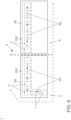
- the Fig. 4 a light unit 100 can be seen, which consists of three light modules (as described).
- the components 10, as well as the light bodies 30, can therefore be produced in a simple manner in one operation, preferably in one injection molding tool.
- each of the connecting elements 19 has a curved shape in cross section, so that a semicircular receiving space 19a is created.
- the receiving space 19a serves during assembly to accommodate the connecting element 37, which has a semicircular cross-section (cf Fig. 5 ).
- circuit board 50' which is correspondingly longer than the circuit board 50 (cf. Fig. 1 ) and several, preferably three, light sources 51, which are assigned to the light bodies 30.
- the light modules 1 or light units 100 'or 100" consisting of these can also be used in a lighting device 2 of a motor vehicle indicated by dashed lines.
- the lighting device 2 can be a rear lighting of a motor vehicle, with a body-side part 2a of the lighting device 2 in one Body 3 and a tailgate-side part 2b of the lighting device 2 can be installed in a tailgate 4 of a motor vehicle.
- control unit not shown here, it is conceivable to control the individual light modules 1 one after the other in such a way that lighting animations A1 or A2 (compare arrow direction) are generated. This is conceivable, for example, to implement a so-called coming home or leaving home function.
- FIG. 7 a motor vehicle K, in which two lighting devices 2 serving as rear lights are installed.
- a control unit 5 is used to control the lighting devices 2 via signal and control lines S.
Landscapes
- Engineering & Computer Science (AREA)
- General Engineering & Computer Science (AREA)
- Physics & Mathematics (AREA)
- Optics & Photonics (AREA)
- General Physics & Mathematics (AREA)
- Microelectronics & Electronic Packaging (AREA)
- Non-Portable Lighting Devices Or Systems Thereof (AREA)
- Arrangements Of Lighting Devices For Vehicle Interiors, Mounting And Supporting Thereof, Circuits Therefore (AREA)
- Planar Illumination Modules (AREA)
- Led Device Packages (AREA)
Claims (10)
- Unité lumineuse (100, 100', 100'') destinée à être utilisée dans un dispositif d'éclairage (2 ; 2a, 2b) destiné à un véhicule automobile (K), ladite unité lumineuse comprenant au moins un module lumineux (1) pourvu d'un corps lumineux (30) sensiblement bidimensionnel conçu comme guide de lumière et au moins un moyen luminescent (51) dont les rayons lumineux (L) sont injectés par couplage ou peuvent être injectés par couplage dans une surface latérale (34) du corps lumineux (30), les rayons lumineux (L) sortant ou pouvant sortir vers l'extérieur par le biais d'une surface de sortie de lumière (35) entourée de surfaces latérales (31-34) du corps lumineux (30) et au moins une partie des surfaces latérales (31-34) et une surface arrière (36), opposée à la surface de sortie de lumière (35), étant recouvertes par un couvercle réfléchissant ou à rétro-dispersion diffuse (10), le couvercle (10) d'un corps lumineux (30) étant formé par un composant (10) en forme de cadre pourvu d'une paroi arrière (16) et d'une ouverture (17) opposée à la paroi arrière (16), les dimensions du corps lumineux (30) étant conçues de manière que, dans sa position de montage, celui-ci remplisse sensiblement le composant (10) en forme de cadre, caractérisée en ce qu'une paroi latérale (14) du composant (10) en forme de cadre comporte une ouverture (15) par laquelle le corps lumineux (30) est inséré latéralement dans le composant (10) en forme de cadre, l'au moins un moyen luminescent (51) étant disposé sur la paroi latérale (14) du composant (10) en forme de cadre qui comporte l'ouverture (15), le corps lumineux (30) ayant un facteur de transmission dans une gamme d'environ 85 % à environ 95 % et l'unité lumineuse (100, 100', 100'') étant formée de plusieurs modules lumineux (1) dans lesquels les composants (10) en forme de cadre d'une part et les corps lumineux (30) sensiblement bidimensionnels d'autre part sont reliés respectivement entre eux d'une seule pièce et les composants (10) en forme de cadre étant fixés à une carte de circuit imprimé commune (50') qui porte les moyens luminescents (51) associés aux corps lumineux (30) sensiblement bidimensionnels.
- Unité lumineuse (100, 100', 100'') selon la revendication 1, caractérisée en ce que des impuretés photo-dispersantes (38) sont disposées de manière répartie dans chaque corps lumineux (30).
- Unité lumineuse (100, 100', 100'') selon la revendication 2, caractérisée en ce que chaque corps lumineux (30) a un facteur de transmission d'environ 92 %.
- Unité lumineuse (100, 100', 100'') selon l'une des revendications précédentes, caractérisée en ce que chacun de l'au moins un moyen luminescent (51) est disposé à une distance (b) de la paroi latérale (14).
- Unité lumineuse (100, 100', 100'') selon l'une des revendications précédentes, caractérisée en ce qu'au moins une optique collectrice (60) est disposée entre l'au moins un moyen luminescent (51) et la paroi latérale (14).
- Unité lumineuse (100, 100', 100'') selon l'une des revendications précédentes, caractérisée en ce que chaque composant (10) en forme de cadre est fixé par le biais d'un support (53) à la carte de circuit imprimé (50, 50') qui porte également chacun de l'au moins un moyen luminescent (51).
- Unité lumineuse (100, 100', 100'') selon la revendication 6, caractérisée en ce que le composant (10) en forme de cadre est à chaque fois encliqueté au support (53).
- Unité lumineuse (100, 100', 100'') selon l'une des revendications précédentes, caractérisée en ce que plusieurs moyens luminescents (51) conçus sous la forme de diodes électroluminescentes sont prévus qui sont à une distance mutuelle (a) les uns des autres supérieure à 4,5 mm et inférieure à 6,5 mm.
- Dispositif d'éclairage (2 ; 2a, 2b) destiné à un véhicule automobile (K), caractérisé par au moins une unité lumineuse (100, 100', 100") selon l'une des revendications 1 à 8.
- Véhicule automobile, caractérisé par au moins un dispositif d'éclairage (2 ; 2a, 2b) selon la revendication 9.
Applications Claiming Priority (2)
| Application Number | Priority Date | Filing Date | Title |
|---|---|---|---|
| DE102018215988.2A DE102018215988A1 (de) | 2018-09-19 | 2018-09-19 | Lichtmodul, insbesondere zur Verwendung in einer Beleuchtungsvorrichtung für ein Kraftfahrzeug |
| PCT/EP2019/074788 WO2020058236A1 (fr) | 2018-09-19 | 2019-09-17 | Module d'éclairage, notamment destiné à être utilisé dans un dispositif d'éclairage pour véhicule automobile |
Publications (3)
| Publication Number | Publication Date |
|---|---|
| EP3853518A1 EP3853518A1 (fr) | 2021-07-28 |
| EP3853518C0 EP3853518C0 (fr) | 2023-11-29 |
| EP3853518B1 true EP3853518B1 (fr) | 2023-11-29 |
Family
ID=68062901
Family Applications (1)
| Application Number | Title | Priority Date | Filing Date |
|---|---|---|---|
| EP19773759.6A Active EP3853518B1 (fr) | 2018-09-19 | 2019-09-17 | Module d'éclairage, notamment destiné à être utilisé dans un dispositif d'éclairage pour véhicule automobile |
Country Status (6)
| Country | Link |
|---|---|
| US (1) | US11408580B2 (fr) |
| EP (1) | EP3853518B1 (fr) |
| CN (1) | CN112739951B (fr) |
| DE (1) | DE102018215988A1 (fr) |
| ES (1) | ES2971107T3 (fr) |
| WO (1) | WO2020058236A1 (fr) |
Families Citing this family (2)
| Publication number | Priority date | Publication date | Assignee | Title |
|---|---|---|---|---|
| DE102020208105B4 (de) * | 2020-06-30 | 2025-02-06 | Volkswagen Aktiengesellschaft | Kraftfahrzeug mit wenigstens einer Beleuchtungsvorrichtung im Bereich einer Klappe sowie Teil einer Beleuchtungsvorrichtung für ein Kraftfahrzeug |
| CN218954705U (zh) * | 2022-11-25 | 2023-05-02 | 法雷奥市光(中国)车灯有限公司 | 光学照射组件、照明设备以及机动车辆 |
Family Cites Families (30)
| Publication number | Priority date | Publication date | Assignee | Title |
|---|---|---|---|---|
| US5150960A (en) * | 1991-12-06 | 1992-09-29 | General Motors Corporation | Rear license plate illumination |
| DE19902774A1 (de) | 1999-01-25 | 2000-08-10 | Willing Gmbh Dr Ing | Leuchtkörper mit Leuchtdioden für Selbstleuchter und zur Hinterleuchtung von Hinweiselementen |
| US6428175B1 (en) | 1998-09-14 | 2002-08-06 | Dr.-Ing. Willing Gmbh | Advisory lighting fitting |
| JP2002533892A (ja) | 1998-12-29 | 2002-10-08 | オスラム オプト セミコンダクターズ ゲゼルシャフト ミット ベシュレンクテル ハフツング | 側方に斜めの光入力結合部を有する光源素子 |
| DE19860697A1 (de) | 1998-12-29 | 2000-08-10 | Osram Opto Semiconductors Gmbh | Verfahren zur Herstellung eines flachen Lichtleitermoduls |
| DE10238073A1 (de) * | 2002-08-21 | 2004-03-04 | Hella Kg Hueck & Co. | Fahrzeugleuchte |
| US7156534B2 (en) * | 2004-03-03 | 2007-01-02 | Coretronic Corporation | Backlight module |
| JP4780788B2 (ja) * | 2007-01-31 | 2011-09-28 | スタンレー電気株式会社 | Led灯具ユニット |
| KR101385204B1 (ko) * | 2007-05-25 | 2014-04-14 | 삼성디스플레이 주식회사 | 백라이트 어셈블리 및 이를 구비한 액정표시장치 |
| US8089582B2 (en) * | 2007-05-31 | 2012-01-03 | Hitachi Displays, Ltd. | Liquid crystal display device comprising at least one groove having an end portion that stops short of the non-adjacent opposite side surfaces and extends in a direction perpendicular to the non-adjacent side surfaces |
| KR20090073886A (ko) * | 2007-12-31 | 2009-07-03 | 엘지디스플레이 주식회사 | 액정표시장치 |
| DE102009053581B3 (de) * | 2009-10-05 | 2011-03-03 | Automotive Lighting Reutlingen Gmbh | Lichtmodul für eine Beleuchtungseinrichtung eines Kraftfahrzeugs |
| US20120257107A1 (en) * | 2009-12-28 | 2012-10-11 | Sharp Kabushiki Kaisha | Illumination device, liquid crystal display device and television receiver device |
| JP5440857B2 (ja) | 2010-03-05 | 2014-03-12 | スタンレー電気株式会社 | 車両用灯具ユニット、及び、車両用灯具 |
| KR101719693B1 (ko) * | 2010-05-11 | 2017-03-27 | 삼성디스플레이 주식회사 | 발광 다이오드 패키지 및 이를 포함하는 표시 장치 |
| EP2428724B1 (fr) | 2010-09-08 | 2017-03-29 | SMR Patents S.à.r.l. | Couplage de lumière optimal pour dispositifs rétroviseurs |
| DE102011110630A1 (de) | 2011-08-18 | 2013-02-21 | Volkswagen Aktiengesellschaft | Verfahren zur Ansteuerung von Leuchtmitteln einer Beleuchtungseinrichtung für ein Kraftzeug und Beleuchtungseinrichtung |
| DE102011110629B4 (de) | 2011-08-18 | 2025-04-03 | Volkswagen Aktiengesellschaft | Beleuchtungsvorrichtung |
| JP2013058396A (ja) | 2011-09-08 | 2013-03-28 | Koito Mfg Co Ltd | 車両用灯具 |
| US9022631B2 (en) * | 2012-06-13 | 2015-05-05 | Innotec Corp. | Flexible light pipe |
| ITTV20130190A1 (it) | 2013-11-20 | 2015-05-21 | Automotive Lighting Italia Spa | Fanale automobilistico |
| DE102014110225A1 (de) * | 2014-07-21 | 2016-01-21 | Osram Opto Semiconductors Gmbh | Fahrzeugleuchte |
| KR102305599B1 (ko) | 2014-10-22 | 2021-09-28 | 엘지이노텍 주식회사 | 조명장치 및 이를 포함하는 차량용 램프 |
| JP6514912B2 (ja) * | 2015-02-26 | 2019-05-15 | 株式会社村上開明堂 | ターンランプ |
| KR101702589B1 (ko) * | 2015-11-30 | 2017-02-03 | 엘지디스플레이 주식회사 | 홀을 구비한 이형 디스플레이 |
| KR20170064664A (ko) * | 2015-12-02 | 2017-06-12 | 엘지이노텍 주식회사 | 조명장치 및 이를 포함하는 차량용 램프 |
| KR101873279B1 (ko) | 2016-06-10 | 2018-07-03 | (주)미경테크 | 백라이트 유닛 및 이의 제조 방법 |
| WO2019037803A1 (fr) * | 2017-08-22 | 2019-02-28 | Varroc Lighting Systems, s.r.o. | Dispositif lumineux d'un véhicule automobile |
| CZ2017773A3 (cs) * | 2017-12-01 | 2019-06-12 | Varroc Lighting Systems, s.r.o. | Světelné zařízení, zejména signální svítilna, pro motorová vozidla |
| KR102564889B1 (ko) * | 2018-02-08 | 2023-08-09 | 주식회사 아모센스 | 자동차의 리어 램프 모듈 및 이를 갖는 리어 콤비네이션 램프 |
-
2018
- 2018-09-19 DE DE102018215988.2A patent/DE102018215988A1/de not_active Withdrawn
-
2019
- 2019-09-17 US US17/277,851 patent/US11408580B2/en active Active
- 2019-09-17 CN CN201980060882.1A patent/CN112739951B/zh active Active
- 2019-09-17 EP EP19773759.6A patent/EP3853518B1/fr active Active
- 2019-09-17 WO PCT/EP2019/074788 patent/WO2020058236A1/fr not_active Ceased
- 2019-09-17 ES ES19773759T patent/ES2971107T3/es active Active
Also Published As
| Publication number | Publication date |
|---|---|
| EP3853518C0 (fr) | 2023-11-29 |
| EP3853518A1 (fr) | 2021-07-28 |
| ES2971107T3 (es) | 2024-06-03 |
| US11408580B2 (en) | 2022-08-09 |
| WO2020058236A1 (fr) | 2020-03-26 |
| CN112739951B (zh) | 2023-04-25 |
| US20210348737A1 (en) | 2021-11-11 |
| CN112739951A (zh) | 2021-04-30 |
| DE102018215988A1 (de) | 2020-03-19 |
Similar Documents
| Publication | Publication Date | Title |
|---|---|---|
| EP2816276B1 (fr) | Véhicule automobile doté d'un dispositif d'éclairage | |
| EP3141797B1 (fr) | Éclairage lineaire | |
| DE102016007709B4 (de) | Kraftfahrzeugzierteil | |
| DE102004054732B4 (de) | Lichtleiteranordung | |
| WO2018149741A1 (fr) | Dispositif d'éclairage pour une pièce d'équipement intérieur | |
| DE102020207459A1 (de) | Beleuchtungsvorrichtung für ein Kraftfahrzeug | |
| WO2020043532A1 (fr) | Dispositif d'éclairage destiné à un véhicule automobile | |
| DE102012103310A1 (de) | Beleuchtungsvorrichtung für Fahrzeuge | |
| WO2000039501A1 (fr) | Source lumineuse a couplage lateral oblique de lumiere | |
| DE102008056985A1 (de) | Zierleuchteneinheit für Fahrzeuge | |
| EP3853518B1 (fr) | Module d'éclairage, notamment destiné à être utilisé dans un dispositif d'éclairage pour véhicule automobile | |
| DE102006035842B4 (de) | Fahrzeugleuchte mit einer einstückigen Lichtleiter-Blenden-Einheit | |
| DE102013007856A1 (de) | Lichtleitkörper und Leuchtvorrichtung mit dem Lichtleitkörper | |
| EP1818698A1 (fr) | Dispositif d'éclairage pour un écran réflecteur, dispositif d'écran éclairé tout comme support | |
| EP3158260B1 (fr) | Dispositif d'éclairage de véhicule automobile | |
| EP4166843A1 (fr) | Dispositif d'éclairage pour un véhicule automobile | |
| DE202005014267U1 (de) | Fahrzeugleuchte mit einem Lichtleiter mit zentraler Lichteinkopplung | |
| DE112016001066T5 (de) | Hoch montierte bremsleuchte für ein automobil | |
| DE102018202127A1 (de) | Beleuchtungsvorrichtung zur Erzeugung eines Ambientelichts im Innenraum eines Kraftfahrzeugs | |
| DE102014102355A1 (de) | Beleuchtungsvorrichtung für Fahrzeuge | |
| DE102020201645A1 (de) | Beleuchtungsvorrichtung für ein Kraftfahrzeug | |
| DE102021117619A1 (de) | Beleuchtungsvorrichtung für den Außenraum eines Kraftfahrzeugs | |
| DE102010050955A1 (de) | Beleuchtungsvorrichtung für Fahrzeuge | |
| DE102020201648A1 (de) | Beleuchtungsvorrichtung für ein Kraftfahrzeug | |
| DE102015106242B4 (de) | Begrenzungsleuchte für Fahrzeuge |
Legal Events
| Date | Code | Title | Description |
|---|---|---|---|
| STAA | Information on the status of an ep patent application or granted ep patent |
Free format text: STATUS: UNKNOWN |
|
| STAA | Information on the status of an ep patent application or granted ep patent |
Free format text: STATUS: THE INTERNATIONAL PUBLICATION HAS BEEN MADE |
|
| PUAI | Public reference made under article 153(3) epc to a published international application that has entered the european phase |
Free format text: ORIGINAL CODE: 0009012 |
|
| STAA | Information on the status of an ep patent application or granted ep patent |
Free format text: STATUS: REQUEST FOR EXAMINATION WAS MADE |
|
| 17P | Request for examination filed |
Effective date: 20210419 |
|
| AK | Designated contracting states |
Kind code of ref document: A1 Designated state(s): AL AT BE BG CH CY CZ DE DK EE ES FI FR GB GR HR HU IE IS IT LI LT LU LV MC MK MT NL NO PL PT RO RS SE SI SK SM TR |
|
| DAV | Request for validation of the european patent (deleted) | ||
| DAX | Request for extension of the european patent (deleted) | ||
| STAA | Information on the status of an ep patent application or granted ep patent |
Free format text: STATUS: EXAMINATION IS IN PROGRESS |
|
| 17Q | First examination report despatched |
Effective date: 20230214 |
|
| GRAP | Despatch of communication of intention to grant a patent |
Free format text: ORIGINAL CODE: EPIDOSNIGR1 |
|
| STAA | Information on the status of an ep patent application or granted ep patent |
Free format text: STATUS: GRANT OF PATENT IS INTENDED |
|
| INTG | Intention to grant announced |
Effective date: 20230623 |
|
| GRAS | Grant fee paid |
Free format text: ORIGINAL CODE: EPIDOSNIGR3 |
|
| GRAA | (expected) grant |
Free format text: ORIGINAL CODE: 0009210 |
|
| STAA | Information on the status of an ep patent application or granted ep patent |
Free format text: STATUS: THE PATENT HAS BEEN GRANTED |
|
| AK | Designated contracting states |
Kind code of ref document: B1 Designated state(s): AL AT BE BG CH CY CZ DE DK EE ES FI FR GB GR HR HU IE IS IT LI LT LU LV MC MK MT NL NO PL PT RO RS SE SI SK SM TR |
|
| REG | Reference to a national code |
Ref country code: GB Ref legal event code: FG4D Free format text: NOT ENGLISH |
|
| REG | Reference to a national code |
Ref country code: CH Ref legal event code: EP |
|
| REG | Reference to a national code |
Ref country code: DE Ref legal event code: R096 Ref document number: 502019010039 Country of ref document: DE |
|
| REG | Reference to a national code |
Ref country code: IE Ref legal event code: FG4D Free format text: LANGUAGE OF EP DOCUMENT: GERMAN |
|
| U01 | Request for unitary effect filed |
Effective date: 20231213 |
|
| U07 | Unitary effect registered |
Designated state(s): AT BE BG DE DK EE FI FR IT LT LU LV MT NL PT SE SI Effective date: 20231219 |
|
| PG25 | Lapsed in a contracting state [announced via postgrant information from national office to epo] |
Ref country code: GR Free format text: LAPSE BECAUSE OF FAILURE TO SUBMIT A TRANSLATION OF THE DESCRIPTION OR TO PAY THE FEE WITHIN THE PRESCRIBED TIME-LIMIT Effective date: 20240301 |
|
| PG25 | Lapsed in a contracting state [announced via postgrant information from national office to epo] |
Ref country code: IS Free format text: LAPSE BECAUSE OF FAILURE TO SUBMIT A TRANSLATION OF THE DESCRIPTION OR TO PAY THE FEE WITHIN THE PRESCRIBED TIME-LIMIT Effective date: 20240329 |
|
| PG25 | Lapsed in a contracting state [announced via postgrant information from national office to epo] |
Ref country code: IS Free format text: LAPSE BECAUSE OF FAILURE TO SUBMIT A TRANSLATION OF THE DESCRIPTION OR TO PAY THE FEE WITHIN THE PRESCRIBED TIME-LIMIT Effective date: 20240329 Ref country code: GR Free format text: LAPSE BECAUSE OF FAILURE TO SUBMIT A TRANSLATION OF THE DESCRIPTION OR TO PAY THE FEE WITHIN THE PRESCRIBED TIME-LIMIT Effective date: 20240301 |
|
| PG25 | Lapsed in a contracting state [announced via postgrant information from national office to epo] |
Ref country code: RS Free format text: LAPSE BECAUSE OF FAILURE TO SUBMIT A TRANSLATION OF THE DESCRIPTION OR TO PAY THE FEE WITHIN THE PRESCRIBED TIME-LIMIT Effective date: 20231129 Ref country code: PL Free format text: LAPSE BECAUSE OF FAILURE TO SUBMIT A TRANSLATION OF THE DESCRIPTION OR TO PAY THE FEE WITHIN THE PRESCRIBED TIME-LIMIT Effective date: 20231129 Ref country code: NO Free format text: LAPSE BECAUSE OF FAILURE TO SUBMIT A TRANSLATION OF THE DESCRIPTION OR TO PAY THE FEE WITHIN THE PRESCRIBED TIME-LIMIT Effective date: 20240229 Ref country code: HR Free format text: LAPSE BECAUSE OF FAILURE TO SUBMIT A TRANSLATION OF THE DESCRIPTION OR TO PAY THE FEE WITHIN THE PRESCRIBED TIME-LIMIT Effective date: 20231129 |
|
| REG | Reference to a national code |
Ref country code: ES Ref legal event code: FG2A Ref document number: 2971107 Country of ref document: ES Kind code of ref document: T3 Effective date: 20240603 |
|
| PG25 | Lapsed in a contracting state [announced via postgrant information from national office to epo] |
Ref country code: CZ Free format text: LAPSE BECAUSE OF FAILURE TO SUBMIT A TRANSLATION OF THE DESCRIPTION OR TO PAY THE FEE WITHIN THE PRESCRIBED TIME-LIMIT Effective date: 20231129 |
|
| PG25 | Lapsed in a contracting state [announced via postgrant information from national office to epo] |
Ref country code: SK Free format text: LAPSE BECAUSE OF FAILURE TO SUBMIT A TRANSLATION OF THE DESCRIPTION OR TO PAY THE FEE WITHIN THE PRESCRIBED TIME-LIMIT Effective date: 20231129 |
|
| PG25 | Lapsed in a contracting state [announced via postgrant information from national office to epo] |
Ref country code: SM Free format text: LAPSE BECAUSE OF FAILURE TO SUBMIT A TRANSLATION OF THE DESCRIPTION OR TO PAY THE FEE WITHIN THE PRESCRIBED TIME-LIMIT Effective date: 20231129 Ref country code: SK Free format text: LAPSE BECAUSE OF FAILURE TO SUBMIT A TRANSLATION OF THE DESCRIPTION OR TO PAY THE FEE WITHIN THE PRESCRIBED TIME-LIMIT Effective date: 20231129 Ref country code: RO Free format text: LAPSE BECAUSE OF FAILURE TO SUBMIT A TRANSLATION OF THE DESCRIPTION OR TO PAY THE FEE WITHIN THE PRESCRIBED TIME-LIMIT Effective date: 20231129 Ref country code: CZ Free format text: LAPSE BECAUSE OF FAILURE TO SUBMIT A TRANSLATION OF THE DESCRIPTION OR TO PAY THE FEE WITHIN THE PRESCRIBED TIME-LIMIT Effective date: 20231129 |
|
| REG | Reference to a national code |
Ref country code: DE Ref legal event code: R097 Ref document number: 502019010039 Country of ref document: DE |
|
| PLBE | No opposition filed within time limit |
Free format text: ORIGINAL CODE: 0009261 |
|
| STAA | Information on the status of an ep patent application or granted ep patent |
Free format text: STATUS: NO OPPOSITION FILED WITHIN TIME LIMIT |
|
| U20 | Renewal fee for the european patent with unitary effect paid |
Year of fee payment: 6 Effective date: 20240926 |
|
| 26N | No opposition filed |
Effective date: 20240830 |
|
| PG25 | Lapsed in a contracting state [announced via postgrant information from national office to epo] |
Ref country code: MC Free format text: LAPSE BECAUSE OF FAILURE TO SUBMIT A TRANSLATION OF THE DESCRIPTION OR TO PAY THE FEE WITHIN THE PRESCRIBED TIME-LIMIT Effective date: 20231129 |
|
| REG | Reference to a national code |
Ref country code: CH Ref legal event code: PL |
|
| PG25 | Lapsed in a contracting state [announced via postgrant information from national office to epo] |
Ref country code: CH Free format text: LAPSE BECAUSE OF NON-PAYMENT OF DUE FEES Effective date: 20240930 |
|
| PG25 | Lapsed in a contracting state [announced via postgrant information from national office to epo] |
Ref country code: IE Free format text: LAPSE BECAUSE OF NON-PAYMENT OF DUE FEES Effective date: 20240917 |
|
| PGFP | Annual fee paid to national office [announced via postgrant information from national office to epo] |
Ref country code: GB Payment date: 20250923 Year of fee payment: 7 |
|
| U20 | Renewal fee for the european patent with unitary effect paid |
Year of fee payment: 7 Effective date: 20250925 |
|
| PG25 | Lapsed in a contracting state [announced via postgrant information from national office to epo] |
Ref country code: CY Free format text: LAPSE BECAUSE OF FAILURE TO SUBMIT A TRANSLATION OF THE DESCRIPTION OR TO PAY THE FEE WITHIN THE PRESCRIBED TIME-LIMIT; INVALID AB INITIO Effective date: 20190917 |
|
| PGFP | Annual fee paid to national office [announced via postgrant information from national office to epo] |
Ref country code: ES Payment date: 20251008 Year of fee payment: 7 |
|
| PG25 | Lapsed in a contracting state [announced via postgrant information from national office to epo] |
Ref country code: HU Free format text: LAPSE BECAUSE OF FAILURE TO SUBMIT A TRANSLATION OF THE DESCRIPTION OR TO PAY THE FEE WITHIN THE PRESCRIBED TIME-LIMIT; INVALID AB INITIO Effective date: 20190917 |