EP3853671B1 - Elastisches halterungsorgan für die befestigung einer uhrenkomponente auf einem halteelement - Google Patents
Elastisches halterungsorgan für die befestigung einer uhrenkomponente auf einem halteelement Download PDFInfo
- Publication number
- EP3853671B1 EP3853671B1 EP19759404.7A EP19759404A EP3853671B1 EP 3853671 B1 EP3853671 B1 EP 3853671B1 EP 19759404 A EP19759404 A EP 19759404A EP 3853671 B1 EP3853671 B1 EP 3853671B1
- Authority
- EP
- European Patent Office
- Prior art keywords
- elastic
- retaining member
- support element
- arms
- rigid
- Prior art date
- Legal status (The legal status is an assumption and is not a legal conclusion. Google has not performed a legal analysis and makes no representation as to the accuracy of the status listed.)
- Active
Links
Images

Classifications
-
- G—PHYSICS
- G04—HOROLOGY
- G04B—MECHANICALLY-DRIVEN CLOCKS OR WATCHES; MECHANICAL PARTS OF CLOCKS OR WATCHES IN GENERAL; TIME PIECES USING THE POSITION OF THE SUN, MOON OR STARS
- G04B17/00—Mechanisms for stabilising frequency
- G04B17/32—Component parts or constructional details, e.g. collet, stud, virole or piton
- G04B17/34—Component parts or constructional details, e.g. collet, stud, virole or piton for fastening the hairspring onto the balance
- G04B17/345—Details of the spiral roll
-
- G—PHYSICS
- G04—HOROLOGY
- G04B—MECHANICALLY-DRIVEN CLOCKS OR WATCHES; MECHANICAL PARTS OF CLOCKS OR WATCHES IN GENERAL; TIME PIECES USING THE POSITION OF THE SUN, MOON OR STARS
- G04B13/00—Gearwork
- G04B13/02—Wheels; Pinions; Spindles; Pivots
- G04B13/021—Wheels; Pinions; Spindles; Pivots elastic fitting with a spindle, axis or shaft
- G04B13/022—Wheels; Pinions; Spindles; Pivots elastic fitting with a spindle, axis or shaft with parts made of hard material, e.g. silicon, diamond, sapphire, quartz and the like
-
- G—PHYSICS
- G04—HOROLOGY
- G04B—MECHANICALLY-DRIVEN CLOCKS OR WATCHES; MECHANICAL PARTS OF CLOCKS OR WATCHES IN GENERAL; TIME PIECES USING THE POSITION OF THE SUN, MOON OR STARS
- G04B17/00—Mechanisms for stabilising frequency
- G04B17/32—Component parts or constructional details, e.g. collet, stud, virole or piton
Definitions
- the invention relates to an elastic holding member for fixing a timepiece component to a support element.
- the invention also relates to an elastic retaining member-timepiece component assembly and an assembly of such an assembly with the support element.
- the invention also relates to a method for making such an assembly.
- the invention further relates to a timepiece movement comprising at least one such assembly.
- the invention finally relates to a timepiece comprising such a movement.
- the object of the present invention is to overcome all or part of the drawbacks mentioned above by proposing an elastic holding member which has a high holding torque, in particular to facilitate/simplify the assembly operations of an assembly of a elastic holding - watch component with a support element as well as ensuring sufficient holding to guarantee holding in position in the plane and guaranteeing its angular position during the life of the component.
- the invention relates to an elastic holding member for fixing a timepiece component to a support element, comprising an opening into which said support element can be inserted, the support comprising rigid arms and elastic arms defined between connection zones contributing to ensure elastic clamping of the support element in the opening, each rigid arm being provided with two flat contact zones of the support member capable of cooperate with corresponding convex contact portions of the support element and in that said rigid or elastic arms each extend longitudinally between connecting zones, these rigid arms and these elastic arms being arranged in the holding member successively and alternately and each rigid arm has a volume of material greater than the volume of material constituting each elastic arm.
- the invention also relates to an elastic holding member-timepiece component assembly for a clockwork movement of a timepiece comprising such a holding member.
- the assembly is one-piece.
- the invention also relates to an assembly for a timepiece movement of a timepiece comprising an elastic retaining member-timepiece component assembly, said assembly being fixed to a support element.
- the invention further relates to a timepiece movement comprising at least one such assembly.
- the invention also relates to a timepiece comprising such a timepiece movement.
- the elastic holding member is then capable of supporting a substantial elastic tightening and therefore of storing a large quantity of elastic energy when it is constrained in order to restore a high holding torque, in particular thanks to a significant rigidity of this elastic retaining member induced in particular by substantial volumes (or quantities) of material constituting its rigid arms which include the internal and external structures. It will be noted that these large volumes of material are more precisely included in the contact zones 8 which are placed under load (or under stress) during the insertion of the support element into this holding member.
- this elastic holding member is configured so that this storage of elastic energy leads to stresses which remain admissible stresses with regard to the material which constitutes such a holding member such as silicon.
- the contact zones 8 have a flat surface which thus allows them to achieve with the contact portions a contact configuration of the plane-convex type, thus contributing to avoiding/preventing any damage to the holding member 1 by the appearance of breaks or cracks.
- the invention also relates to an elastic holding member/timepiece component assembly for a clock movement of a timepiece comprising such an elastic holding member.
- this assembly is in one piece.
- the invention also relates to an assembly for a timepiece movement of a timepiece comprising such an elastic holding member/timepiece component assembly fixed to a support element.
- the invention further relates to the timepiece movement comprising at least one such assembly.
- the invention also relates to the timepiece comprising such a timepiece movement.
- the invention also relates to a method for producing such an assembly.
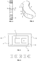
- the figures 1 to 4 present an embodiment of the elastic holding member 1 for fixing a timepiece component 2 on a support element 3.
- the elastic holding member 1 can be a ferrule for the attachment of the timepiece component 2 such as a hairspring to a support element 3 such as a balance shaft.
- this holding member 1 can be included in an assembly 120 elastic holding member - watch component visible on the figure 5 and which is intended to be arranged in a clock movement 110 of a timepiece 100.
- Such an assembly 120 can be a one-piece part made of a so-called “fragile” material, preferably a micro-machinable material. Such a material may comprise silicon, quartz, corundum or even ceramic.
- the elastic retaining member 1 can be made of such a so-called “fragile” material, the timepiece component 2 then being made of another material.
- This assembly 120 can form part of an assembly 130 for the timepiece movement 110, being fixed to the support element 3 by example by elastic tightening. It will be noted that this assembly 130 was designed for applications in the watchmaking field. However, the invention can perfectly be implemented in other fields such as aeronautics, jewelry, or even the automobile.
- Such a holding member 1 comprises an upper face and a lower face 12 which are preferably planar included respectively in first and second planes P1 and P2 visible on the picture 2 , as well as external and internal structures 4a, 4b.
- These external and internal structures 4a, 4b respectively comprise external and internal peripheral walls of this holding member 1 and have different shapes. More specifically, with regard to the external structure 4a, it may have a globally hexagonal shape, including in particular parts having convex shapes. Each of these parts is included in a connecting zone 9 connecting an elastic arm 7 to a rigid arm 6.
- the elastic 7 and rigid 6 arms each being a part of elongated shape which connects parts of the holding member 1 between they. In other words, a rigid arm or an elastic arm extends longitudinally between two connecting zones 9.
- This external structure 4a is in particular intended to be connected to the timepiece component 2 via at least one attachment point 11 arranged in the external peripheral wall of the holding member 1.
- the internal structure 4b it has a non-triangular shape.
- This internal structure 4b which comprises the internal peripheral wall of this holding member 1, participates in defining an opening 5 of such a holding member 1 in which the support element 3 is intended to be inserted.
- This opening 5 defines a volume in the holding member 1 which is less than that of a connecting part of one end of the support element 3 which is intended to be arranged there.
- this connecting part has a circular cross-section and comprises all or part of the convex contact portions 10 defined on the peripheral wall 13 of the support element 3.
- this support element 3 has a radius of curvature R1 visible on the figure 1 .
- the inner faces of the elastic arms 7 are essentially planar and the inner faces of the rigid arms 6 are non-planar, being for example substantially corrugated in whole or in part.
- the inner face of each rigid arm 6 comprises a substantially hollow or substantially concave part in which are included two contact zones 8. These two contact zones 8 are capable of cooperating with the corresponding contact portions 10 of the support element 3.
- Such contact zones 8 are defined in the inner face, in particular in a concave part of this inner face, extending substantially over all or part of the thickness of the holding member 1.
- these contact zones 8 are flat, each comprising a surface which is wholly or partly flat.
- the two contact zones 8 of each rigid arm 8, otherwise called flat contact zones 8, are respectively included in different planes together forming an obtuse angle. These two contact zones 8 of each rigid arm are separated by being spaced apart from each other.
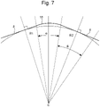
- the inner face comprises a separation zone 18 of the two contact zones 8 of each rigid arm 6 visible on the figure 4 and 7 .
- This connection zone 18 comprises two ends which define with the central axis C an angle ⁇ comprised between about 1 and 9 degrees and which can preferably be 2 degrees.
- the contact zones 8 they each comprise two ends which define with the central axis C an angle ⁇ of between about 1 and 15 degrees, and which can preferably be 10 degrees.
- the contact zones 8 of the rigid arms 6 are provided in particular to cooperate with the contact portions 10 according to a plane-convex type contact configuration in which configuration where the flat surface of each contact zone 8 cooperates with the contact portion 10 corresponding convex shape of the support element 3. It should be specified here that this convex shape of each contact portion 10 is assessed relative to the flat surface of each corresponding contact zone 8 opposite which this portion 10 is arranged. It will be noted that this flat surface of each contact zone 8 forms a plane tangent to the diameter of the support element. In other words, the flat surface is perpendicular to the diameter and therefore to the radius R1 of the support element.
- each rigid arm 6 makes it possible to exert contact pressure between the holding member 1 and the support element 3 during the production of a mechanical connection between them and this, while consequently reducing the intensity of the stresses at the level of these contact zones 8 and the corresponding contact portions 10 of the support element 3 during assembly and/or fastening of this holding member 1 with the support element 3, which stresses are likely to damage the holding member 1 by the appearance of breaks/breaks or even cracks.
- this contact pressure is estimated from the Hertz pressure equation conventionally but not exclusively implemented for determining a contact pressure between cylindrical or spherical parts having diameters or different radii of curvature.
- this Hertz pressure is defined according to the following equation: P E * F ⁇ LR 1 2
- the two contact zones 8 of each rigid arm 6 are flat and therefore have no radii of curvature R 2 .
- Such contact zones 8 are capable of cooperating with the corresponding contact portions 10 of the support element 3 in the plane-convex type contact configuration.
- the contact pressure defined by the Hertz pressure equation is lower than that relating to contact configurations of the convex-convex type during which the contact zone 8 which then has a radius of curvature R 2 is capable of cooperating with the corresponding contact portion 10 of the support element 3.
- This contact pressure present during the contact configuration of the plano-convex type is lower than those implemented during the other configurations described. previously in particular due to the higher value in this context of the relative radius of curvature R resulting from the absence of a radius of curvature for each flat contact zone 8 of the holding member 1 of the present embodiment.
- the contact pressure is lower than those of these other contact configurations by at least 40%.
- the rigid and elastic arms 6, 7 connect the external and internal structures 4a, 4b to each other, moreover comprising each a part of these external and internal structures 4a, 4b.
- these rigid and elastic arms 6, 7 essentially make it possible to carry out a fixing of the elastic clamping type of the support element 3 in the opening 5 made in this holding member 1 which is defined by the structure internal 4b and in particular by the internal peripheral wall of this holding member 1.
- these rigid arms 6 therefore comprise the only contact zones 8 of the holding member 1 with the support element 3 which can be defined in all or part of the interior faces of these rigid arms 6
- the two contact zones 8 of each rigid arm 6 otherwise called “contact interfaces”, are each provided to cooperate with a peripheral wall 13 of the connecting part of the support element 3 in particular with the contact portions 10 corresponding defined in this peripheral wall 13 of the support element 3.
- the holding member 1 then comprises six contact zones 8 which participate in achieving precise centering of the timepiece component 2, for example a hairspring , in the clockwork 110.
- each rigid arm 6 has a volume of material which is substantially greater or strictly greater than the volume of material constituting each elastic arm 7. It is understood that the more material there is, the more rigid an arm.
- the elasticity or the rigidity of an arm in this holding member 1 is defined relative to the contact zones 8 of this member 1, more precisely relative to the intensity of the deformation of these rigid or elastic arms during of the application of a force on these contact zones 8.
- the external and internal structures 4a, 4b, and in particular the internal and external peripheral walls are separated from each other in this holding member 1 by a variable gap E which then changes depending on whether these structures are included, for example, in an arm rigid 6 or even an elastic arm 7.
- this gap E is a maximum gap E1 when it is defined between parts of internal and external peripheral walls included in each rigid arm 6, i.e. the maximum gap E1 present between the inner and outer faces of this rigid arm 6.
- this maximum difference E1 is defined between a part of the inner face adjoining the substantially hollow part in which are included two contact zones 8 of each rigid arm 6 and an opposite part of the external peripheral wall of this rigid arm 6.
- this gap E is a minimum gap E2 when it is defined between parts of the external and internal peripheral walls included in the elastic arms 7, that is the minimum gap E2 present between the inner and outer faces of this elastic arm 7.
- Such a configuration of the rigid and elastic arms 6, 7 allows the holding member 1 to store a greater quantity of elastic energy for the same tightening in comparison with the holding members of the state of the art. Such a quantity of elastic energy stored in the holding member 1 then makes it possible to obtain a greater holding torque of the holding member on the support element 3 in the assembly 130 of the assembly 120 of the member support - watch component with this support element 3.
- such a configuration of the support member 1 makes it possible to store elastic energy ratios which are 6 to 8 times greater than those of the state-of-the-art maintenance devices.
- each elastic arm 6 7 in the retaining member 1 allows, during insertion with tightening, a deformation of each elastic arm 7 making it possible to accommodate the deformation of the whole of the member holding 1 with the geometry of the connecting part of the support element 3 on which it is assembled.
- the mode of deformation undergone by each elastic arm is a toroidal torsion coupled with a radial expansion.
- the invention also relates to a method for producing the assembly 130 of the assembly 120 of the elastic retaining member - timepiece component with the support element 3.
- This method comprises a step of inserting 13 the support element 3 in the opening 5 of the holding member 1.
- the end of the support element is presented to the entrance of the opening 5 defined in the lower face 12 of the holding member 1 in anticipation of the introduction of the connecting part of this support element 3 into the volume defined in this opening 5.
- This step 13 comprises a sub-step 14 of elastic deformation of the holding member 1 in particular of a central zone of this holding member 1 comprising said opening 5 resulting from the application of a contact force on the contact zones 8 of the rigid arms 6 by the contact portions 10 of the peripheral wall 13 of the connecting part of the support element 3.
- This elastic deformation of the central zone actually generates a deformation of the lower face 12 of the holding member 1 which then has an essentially concave shape, in particular at the level of a part of this face 12 included in the central zone of the holding member 1.
- this lower face 12 is no longer flat and is then no longer entirely comprised in the second plane P2.
- this elastic deformation of the retaining member 1 results from the application of the contact force on the contact zones 8 of the rigid arms 6 by the contact portions 10 of the peripheral wall 13 of the support element 3.
- Such a deformation sub-step 14 comprises a phase of displacement 15 of the rigid arms 6 under the action of the contact force which is applied to them.
- Such a movement of the rigid arms 6 is carried out in a direction comprised between a radial direction B1 with respect to a central axis C common to the support element 3 and to the holding member 1, and a direction B2 coinciding with this axis central C.
- this direction B2 is perpendicular to the direction B1 and is oriented in a defined direction from the lower face 12 towards the upper face.
- the contact force is preferably perpendicular or substantially perpendicular to said contact zone 8.
- each elastic arm 7 is driven at its two ends according to the same direction of rotation B4 by the rigid arms 6 in displacement, to which arms 6 such ends are connected. It will be noted that only part of the body of these elastic arms 7 is deformable in torsion here the ends of these arms 7.
- Such a first deformation contributes in particular to improving the insertion of the support element 3 into the opening 5 of the holding member 1 by participating in avoiding any breakage of the holding member 1 and/or any appearance of a crack in this member 1 during its assembly with the support element 3.
- each elastic arm 7 is pulled at its two ends in the longitudinal direction B3 in opposite directions by the rigid arms 6 on the move, to which arms 6 such ends are connected.
- Such a second deformation contributes in particular to the holding member 1 storing a large quantity of elastic energy.
- This double elastic deformation of the elastic arms 7 can be carried out simultaneously or substantially simultaneously, or even successively or substantially successively. It will be noted in the context of the implementation of the deformation phase that when this double elastic deformation is carried out successively or substantially successively, the first deformation can then be carried out before the second deformation.
- This method then comprises a step 16 of fixing the holding member 1 to the reinforcing element 3.
- a step of fixing 16 comprises a sub-step 17 of performing radial elastic tightening of the holding member 1 on the support element 3. It is therefore understood that in such a state of stress, the holding member 1 stores a large quantity of elastic energy which contributes to giving it a consequent holding torque, in particular allowing optimum twisting by elastic tightening.
Landscapes
- Physics & Mathematics (AREA)
- General Physics & Mathematics (AREA)
- Micromachines (AREA)
- Springs (AREA)
- Electric Clocks (AREA)
Claims (20)
- Elastisches Halteorgan (1) zur Befestigung einer Uhrenkomponente (2) an einem Stützelement (3), das eine Öffnung (5) umfasst, in die das Stützelement (3) eingesetzt werden kann, wobei das Halteorgan (1) starre Arme (6) und elastische Arme (7) umfasst, die zwischen Verbindungszonen (9) definiert sind, welche dazu beitragen, ein elastisches Verspannen des Stützelements (3) in der Öffnung (5) zu gewährleisten, wobei jeder starre Arm (6) mit zwei flachen Berührungszonen (8) des Halteorgans (1) versehen ist, die geeignet sind, mit entsprechenden konvexen Berührungsabschnitten (10) des Stützelements (3) zusammenzuwirken, wobei sich die starren (6) bzw. elastischen Arme (7) jeweils längs zwischen Verbindungszonen (9) erstrecken, wobei diese starren Arme (6) und diese elastischen Arme (7) aufeinanderfolgend und abwechselnd im Halteorgan (1) angeordnet sind und jeder starre Arm (6) ein Materialvolumen aufweist, das größer ist als das Materialvolumen, aus dem jeder elastische Arm (7) besteht.
- Elastisches Halteorgan (1) nach dem vorstehenden Anspruch, dadurch gekennzeichnet, dass die zwei Berührungszonen (8) disjunkt an einer Innenseite jedes starren Arms (6) des Halteorgans (1) verteilt sind, indem sie voneinander beabstandet sind.
- Elastisches Halteorgan (1) nach einem der vorstehenden Ansprüche, dadurch gekennzeichnet, dass jede Berührungszone (8) an einer Innenseite jedes starren Arms (6) des Halteorgans (1) definiert ist, indem sie sich über die gesamte oder einen Teil einer Dicke dieses Halteorgans (1) erstreckt.
- Elastisches Halteorgan (1) nach einem der vorstehenden Ansprüche, dadurch gekennzeichnet, dass jede Berührungszone (8) geeignet ist, mit dem entsprechenden Berührungsabschnitt (10) des Stützelements (3) zusammenzuwirken, indem diese sich in einer Berührungskonfiguration vom plankonvexen Typ befinden.
- Elastisches Halteorgan (1) nach einem der vorstehenden Ansprüche, dadurch gekennzeichnet, dass es ebenso viele Berührungszonen (8) wie Berührungsabschnitte (10) umfasst.
- Elastisches Halteorgan (1) nach einem der vorstehenden Ansprüche, dadurch gekennzeichnet, dass die zwei Berührungszonen (8) jedes starren Arms (6) jeweils in verschiedenen Ebenen liegen, die zusammen einen stumpfen Winkel bilden.
- Elastisches Halteorgan (1) nach einem der vorstehenden Ansprüche, dadurch gekennzeichnet, dass es ebenso viele starre Arme (6) wie elastische Arme (7) umfasst.
- Elastisches Halteorgan (1) nach einem der vorstehenden Ansprüche, dadurch gekennzeichnet, dass jeder starre Arm (6) an seinen zwei gegenüberliegenden Enden mit zwei verschiedenen elastischen Armen (7) verbunden ist.
- Elastisches Halteorgan (1) nach einem der vorstehenden Ansprüche, dadurch gekennzeichnet, dass jeder starre Arm (6) ein Materialvolumen aufweist, das größer ist als das Materialvolumen, aus dem jeder elastische Arm (7) besteht.
- Elastisches Halteorgan (1) nach einem der vorstehenden Ansprüche, dadurch gekennzeichnet, dass jeder elastische Arm (7) einen Querschnitt aufweist, der kleiner ist als ein Querschnitt jedes starren Arms (6).
- Elastisches Halteorgan (1) nach einem der vorstehenden Ansprüche, dadurch gekennzeichnet, dass jeder elastische Arm (7) einen Querschnitt aufweist, der im gesamten Körper dieses elastischen Arms (7) konstant ist.
- Elastisches Halteorgan (1) nach einem der vorstehenden Ansprüche, dadurch gekennzeichnet, dass es einen Punkt zum Verhaken (11) mit der Uhrenkomponente (2) umfasst.
- Elastisches Halteorgan (1) nach einem der vorstehenden Ansprüche, dadurch gekennzeichnet, dass es sich um eine Spiralrolle zur Befestigung der Uhrenkomponente (2), wie etwa eine Spirale mit einem Stützelement (3), wie etwa eine Unruhwelle handelt.
- Elastisches Halteorgan (1) nach einem der vorstehenden Ansprüche, dadurch gekennzeichnet, dass es aus einem Material auf Siliciumbasis hergestellt ist.
- Baugruppe (120) aus elastischem Halteorgan und Uhrenkomponente für ein Uhrwerk (110) einer Uhr (100), die ein Halteorgan (1) nach einem der vorstehenden Ansprüche umfasst.
- Baugruppe (120) nach dem vorstehenden Anspruch, dadurch gekennzeichnet, dass sie einstückig ist.
- Anordnung (130) für ein Uhrwerk (110) einer Uhr (100), die eine Baugruppe (120) aus elastischem Halteorgan und Uhrenkomponente nach einem der Ansprüche 15 und 16 umfasst, wobei die Baugruppe (120) an einem Stützelement (3) befestigt ist.
- Uhrwerk (110), das mindestens eine Anordnung (130) nach dem vorstehenden Anspruch umfasst.
- Uhr (100), die ein Uhrwerk (110) nach dem vorstehenden Anspruch umfasst.
- Verfahren zur Herstellung einer Anordnung (130) einer Baugruppe (120) aus elastischem Halteorgan und Uhrenkomponente mit einem Stützelement (3) nach dem vorstehenden Anspruch, umfassend:- einen Schritt des Einsetzens (13) des Stützelements (3) in die Öffnung (5) des elastischen Halteorgans (1) der Baugruppe (120), wobei der Schritt (13) einen Teilschritt des elastischen Verformens (14) des elastischen Halteorgans (1) mit einer Phase der Verlagerung (15) der starren Arme (6) des elastischen Halteorgans umfasst, die eine zweifache elastische Verformung der elastischen Arme (7) dieses elastischen Halteorgans (1) bewirkt, und- einen Schritt des Befestigens (16) des Halteorgans (1) am Stützelement (3), der einen Teilschritt des Herstellens (17) einer radialen elastischen Verspannung des Halteorgans (1) am Stützelement (3) umfasst.
Applications Claiming Priority (2)
| Application Number | Priority Date | Filing Date | Title |
|---|---|---|---|
| EP18196009.7A EP3627234A1 (de) | 2018-09-21 | 2018-09-21 | Elastisches halterungsorgan für die befestigung einer uhrenkomponente auf einem halteelement |
| PCT/EP2019/073236 WO2020057944A1 (fr) | 2018-09-21 | 2019-08-30 | Organe de maintien élastique pour la fixation d'un composant d'horlogerie sur un élément de support |
Publications (2)
| Publication Number | Publication Date |
|---|---|
| EP3853671A1 EP3853671A1 (de) | 2021-07-28 |
| EP3853671B1 true EP3853671B1 (de) | 2022-08-03 |
Family
ID=63678508
Family Applications (2)
| Application Number | Title | Priority Date | Filing Date |
|---|---|---|---|
| EP18196009.7A Withdrawn EP3627234A1 (de) | 2018-09-21 | 2018-09-21 | Elastisches halterungsorgan für die befestigung einer uhrenkomponente auf einem halteelement |
| EP19759404.7A Active EP3853671B1 (de) | 2018-09-21 | 2019-08-30 | Elastisches halterungsorgan für die befestigung einer uhrenkomponente auf einem halteelement |
Family Applications Before (1)
| Application Number | Title | Priority Date | Filing Date |
|---|---|---|---|
| EP18196009.7A Withdrawn EP3627234A1 (de) | 2018-09-21 | 2018-09-21 | Elastisches halterungsorgan für die befestigung einer uhrenkomponente auf einem halteelement |
Country Status (5)
| Country | Link |
|---|---|
| US (1) | US11921461B2 (de) |
| EP (2) | EP3627234A1 (de) |
| JP (1) | JP7084549B2 (de) |
| CN (1) | CN112740115B (de) |
| WO (1) | WO2020057944A1 (de) |
Family Cites Families (9)
| Publication number | Priority date | Publication date | Assignee | Title |
|---|---|---|---|---|
| DE602004019183D1 (de) * | 2004-04-06 | 2009-03-12 | Nivarox Sa | Spiralrolle ohne Deformation des Fixierungsradius der Spiralfeder und Herstellungsverfahren derartige Spiralrolle |
| CH701075B1 (fr) * | 2007-03-02 | 2010-11-30 | Richemont Int Sa | Ensemble formé d'une roue et de son axe et roue pour un tel ensemble. |
| US9250610B2 (en) * | 2010-03-25 | 2016-02-02 | Rolex S.A. | Split collet with a non-circular opening |
| WO2013045706A2 (fr) * | 2011-09-29 | 2013-04-04 | Rolex S.A. | Ensemble monolithique ressort spiral-virole |
| JP6118037B2 (ja) * | 2012-05-08 | 2017-04-19 | セイコーインスツル株式会社 | ひげ玉、てんぷおよび時計 |
| HK1186057A2 (en) * | 2013-01-14 | 2014-03-07 | Master Dynamic Limited | Stress-relief elastic structure of hairspring collet |
| EP2796940A3 (de) * | 2013-04-23 | 2016-05-04 | Rolex Sa | Uhrkomponente zur Aufnahme eines Organs durch Einpressen |
| EP2876504B1 (de) | 2013-11-20 | 2017-07-26 | ETA SA Manufacture Horlogère Suisse | Schraubenloser Spiralklötzchen-Träger für Uhr |
| EP2916177B1 (de) | 2014-03-05 | 2018-11-07 | Nivarox-FAR S.A. | Spirale, die mit einer Federscheibe gesichert werden muss |
-
2018
- 2018-09-21 EP EP18196009.7A patent/EP3627234A1/de not_active Withdrawn
-
2019
- 2019-08-30 JP JP2021513843A patent/JP7084549B2/ja active Active
- 2019-08-30 EP EP19759404.7A patent/EP3853671B1/de active Active
- 2019-08-30 CN CN201980061795.8A patent/CN112740115B/zh active Active
- 2019-08-30 WO PCT/EP2019/073236 patent/WO2020057944A1/fr not_active Ceased
- 2019-08-30 US US17/273,834 patent/US11921461B2/en active Active
Also Published As
| Publication number | Publication date |
|---|---|
| JP2022500639A (ja) | 2022-01-04 |
| EP3627234A1 (de) | 2020-03-25 |
| CN112740115B (zh) | 2022-06-14 |
| JP7084549B2 (ja) | 2022-06-14 |
| EP3853671A1 (de) | 2021-07-28 |
| CN112740115A (zh) | 2021-04-30 |
| US11921461B2 (en) | 2024-03-05 |
| WO2020057944A1 (fr) | 2020-03-26 |
| US20210325829A1 (en) | 2021-10-21 |
Similar Documents
| Publication | Publication Date | Title |
|---|---|---|
| EP4224257B1 (de) | Monolithische spiralfeder-spiralrolle-anordnung | |
| EP3623876A1 (de) | Spiralrolle mit nicht kreisförmiger öffnung | |
| EP3853672B1 (de) | Elastisches halterungsorgan für die befestigung einer uhrenkomponente auf einem halteelement | |
| EP3818416B1 (de) | Elastisches halterungsorgan für die befestigung einer uhrenkomponente auf einem halteelement | |
| EP3853671B1 (de) | Elastisches halterungsorgan für die befestigung einer uhrenkomponente auf einem halteelement | |
| EP3899670B1 (de) | Elastisches halterungsorgan für die befestigung einer uhrenkomponente auf einem halteelement | |
| CH715369A2 (fr) | Organe de maintien élastique pour la fixation d'un composant d'horlogerie sur un élément de support. | |
| EP3779608A1 (de) | Elastisches halterungsorgan einer uhrenkomponente auf einem halteelement | |
| EP3853670B1 (de) | Elastisches halterungsorgan für die befestigung einer uhrenkomponente auf einem halteelement | |
| CH715664A2 (fr) | Organe de maintien élastique pour la fixation d'un composant d'horlogerie sur un élément de support. | |
| CH715370A2 (fr) | Organe de maintien élastique pour la fixation d'un composant d'horlogerie sur un élément de support. | |
| EP4375762A1 (de) | Einteiliges befestigungselement für eine uhrkomponente auf einem trägerelement | |
| EP3786720A1 (de) | Uhrkomponente zur aufnahme eines organs durch einpressen | |
| EP3953769B1 (de) | Elastisches halterungsorgan für die befestigung einer uhrkomponente auf verschiedenen halteelementen | |
| EP3839656B1 (de) | Unruh für uhrwerk | |
| CH715371A2 (fr) | Organe de maintien élastique pour la fixation d'un composant d'horlogerie sur un élément de support. | |
| EP4375761A1 (de) | Elastisches halteelement zur befestigung einer uhrkomponente an einem trägerelement | |
| CH720277A2 (fr) | Pièce monobloc d'attache d'un composant d'horlogerie sur un élément de support | |
| CH720279A2 (fr) | Organe de maintien élastique pour la fixation d'un composant d'horlogerie sur un élément de support | |
| EP4375760A1 (de) | Befestigungselement für eine uhr | |
| CH715368A2 (fr) | Organe de maintien élastique pour la fixation d'un composant d'horlogerie sur un élément de support. | |
| CH720280A2 (fr) | Elément de fixation pour l'horlogerie | |
| CH716046A2 (fr) | Organe de maintien élastique, tel qu'une virole, pour la fixation d'un composant d'horlogerie sur des éléments de support différents. | |
| CH704257A2 (fr) | Assemblage d'une pièce ne comportant pas de domaine plastique. | |
| CH716972A2 (fr) | Balancier d'horlogerie. |
Legal Events
| Date | Code | Title | Description |
|---|---|---|---|
| STAA | Information on the status of an ep patent application or granted ep patent |
Free format text: STATUS: UNKNOWN |
|
| STAA | Information on the status of an ep patent application or granted ep patent |
Free format text: STATUS: THE INTERNATIONAL PUBLICATION HAS BEEN MADE |
|
| PUAI | Public reference made under article 153(3) epc to a published international application that has entered the european phase |
Free format text: ORIGINAL CODE: 0009012 |
|
| STAA | Information on the status of an ep patent application or granted ep patent |
Free format text: STATUS: REQUEST FOR EXAMINATION WAS MADE |
|
| 17P | Request for examination filed |
Effective date: 20210421 |
|
| AK | Designated contracting states |
Kind code of ref document: A1 Designated state(s): AL AT BE BG CH CY CZ DE DK EE ES FI FR GB GR HR HU IE IS IT LI LT LU LV MC MK MT NL NO PL PT RO RS SE SI SK SM TR |
|
| DAV | Request for validation of the european patent (deleted) | ||
| DAX | Request for extension of the european patent (deleted) | ||
| GRAP | Despatch of communication of intention to grant a patent |
Free format text: ORIGINAL CODE: EPIDOSNIGR1 |
|
| STAA | Information on the status of an ep patent application or granted ep patent |
Free format text: STATUS: GRANT OF PATENT IS INTENDED |
|
| INTG | Intention to grant announced |
Effective date: 20220517 |
|
| GRAS | Grant fee paid |
Free format text: ORIGINAL CODE: EPIDOSNIGR3 |
|
| GRAA | (expected) grant |
Free format text: ORIGINAL CODE: 0009210 |
|
| STAA | Information on the status of an ep patent application or granted ep patent |
Free format text: STATUS: THE PATENT HAS BEEN GRANTED |
|
| AK | Designated contracting states |
Kind code of ref document: B1 Designated state(s): AL AT BE BG CH CY CZ DE DK EE ES FI FR GB GR HR HU IE IS IT LI LT LU LV MC MK MT NL NO PL PT RO RS SE SI SK SM TR |
|
| REG | Reference to a national code |
Ref country code: AT Ref legal event code: REF Ref document number: 1509235 Country of ref document: AT Kind code of ref document: T Effective date: 20220815 Ref country code: CH Ref legal event code: EP |
|
| REG | Reference to a national code |
Ref country code: DE Ref legal event code: R096 Ref document number: 602019017866 Country of ref document: DE |
|
| REG | Reference to a national code |
Ref country code: IE Ref legal event code: FG4D Free format text: LANGUAGE OF EP DOCUMENT: FRENCH |
|
| REG | Reference to a national code |
Ref country code: LT Ref legal event code: MG9D |
|
| REG | Reference to a national code |
Ref country code: NL Ref legal event code: MP Effective date: 20220803 |
|
| PG25 | Lapsed in a contracting state [announced via postgrant information from national office to epo] |
Ref country code: SE Free format text: LAPSE BECAUSE OF FAILURE TO SUBMIT A TRANSLATION OF THE DESCRIPTION OR TO PAY THE FEE WITHIN THE PRESCRIBED TIME-LIMIT Effective date: 20220803 Ref country code: RS Free format text: LAPSE BECAUSE OF FAILURE TO SUBMIT A TRANSLATION OF THE DESCRIPTION OR TO PAY THE FEE WITHIN THE PRESCRIBED TIME-LIMIT Effective date: 20220803 Ref country code: PT Free format text: LAPSE BECAUSE OF FAILURE TO SUBMIT A TRANSLATION OF THE DESCRIPTION OR TO PAY THE FEE WITHIN THE PRESCRIBED TIME-LIMIT Effective date: 20221205 Ref country code: NO Free format text: LAPSE BECAUSE OF FAILURE TO SUBMIT A TRANSLATION OF THE DESCRIPTION OR TO PAY THE FEE WITHIN THE PRESCRIBED TIME-LIMIT Effective date: 20221103 Ref country code: NL Free format text: LAPSE BECAUSE OF FAILURE TO SUBMIT A TRANSLATION OF THE DESCRIPTION OR TO PAY THE FEE WITHIN THE PRESCRIBED TIME-LIMIT Effective date: 20220803 Ref country code: LV Free format text: LAPSE BECAUSE OF FAILURE TO SUBMIT A TRANSLATION OF THE DESCRIPTION OR TO PAY THE FEE WITHIN THE PRESCRIBED TIME-LIMIT Effective date: 20220803 Ref country code: LT Free format text: LAPSE BECAUSE OF FAILURE TO SUBMIT A TRANSLATION OF THE DESCRIPTION OR TO PAY THE FEE WITHIN THE PRESCRIBED TIME-LIMIT Effective date: 20220803 Ref country code: FI Free format text: LAPSE BECAUSE OF FAILURE TO SUBMIT A TRANSLATION OF THE DESCRIPTION OR TO PAY THE FEE WITHIN THE PRESCRIBED TIME-LIMIT Effective date: 20220803 Ref country code: ES Free format text: LAPSE BECAUSE OF FAILURE TO SUBMIT A TRANSLATION OF THE DESCRIPTION OR TO PAY THE FEE WITHIN THE PRESCRIBED TIME-LIMIT Effective date: 20220803 |
|
| REG | Reference to a national code |
Ref country code: AT Ref legal event code: MK05 Ref document number: 1509235 Country of ref document: AT Kind code of ref document: T Effective date: 20220803 |
|
| PG25 | Lapsed in a contracting state [announced via postgrant information from national office to epo] |
Ref country code: PL Free format text: LAPSE BECAUSE OF FAILURE TO SUBMIT A TRANSLATION OF THE DESCRIPTION OR TO PAY THE FEE WITHIN THE PRESCRIBED TIME-LIMIT Effective date: 20220803 Ref country code: IS Free format text: LAPSE BECAUSE OF FAILURE TO SUBMIT A TRANSLATION OF THE DESCRIPTION OR TO PAY THE FEE WITHIN THE PRESCRIBED TIME-LIMIT Effective date: 20221203 Ref country code: HR Free format text: LAPSE BECAUSE OF FAILURE TO SUBMIT A TRANSLATION OF THE DESCRIPTION OR TO PAY THE FEE WITHIN THE PRESCRIBED TIME-LIMIT Effective date: 20220803 Ref country code: GR Free format text: LAPSE BECAUSE OF FAILURE TO SUBMIT A TRANSLATION OF THE DESCRIPTION OR TO PAY THE FEE WITHIN THE PRESCRIBED TIME-LIMIT Effective date: 20221104 |
|
| PG25 | Lapsed in a contracting state [announced via postgrant information from national office to epo] |
Ref country code: SM Free format text: LAPSE BECAUSE OF FAILURE TO SUBMIT A TRANSLATION OF THE DESCRIPTION OR TO PAY THE FEE WITHIN THE PRESCRIBED TIME-LIMIT Effective date: 20220803 Ref country code: RO Free format text: LAPSE BECAUSE OF FAILURE TO SUBMIT A TRANSLATION OF THE DESCRIPTION OR TO PAY THE FEE WITHIN THE PRESCRIBED TIME-LIMIT Effective date: 20220803 Ref country code: LU Free format text: LAPSE BECAUSE OF NON-PAYMENT OF DUE FEES Effective date: 20220830 Ref country code: DK Free format text: LAPSE BECAUSE OF FAILURE TO SUBMIT A TRANSLATION OF THE DESCRIPTION OR TO PAY THE FEE WITHIN THE PRESCRIBED TIME-LIMIT Effective date: 20220803 Ref country code: CZ Free format text: LAPSE BECAUSE OF FAILURE TO SUBMIT A TRANSLATION OF THE DESCRIPTION OR TO PAY THE FEE WITHIN THE PRESCRIBED TIME-LIMIT Effective date: 20220803 Ref country code: AT Free format text: LAPSE BECAUSE OF FAILURE TO SUBMIT A TRANSLATION OF THE DESCRIPTION OR TO PAY THE FEE WITHIN THE PRESCRIBED TIME-LIMIT Effective date: 20220803 |
|
| REG | Reference to a national code |
Ref country code: BE Ref legal event code: MM Effective date: 20220831 |
|
| REG | Reference to a national code |
Ref country code: DE Ref legal event code: R097 Ref document number: 602019017866 Country of ref document: DE |
|
| PG25 | Lapsed in a contracting state [announced via postgrant information from national office to epo] |
Ref country code: SK Free format text: LAPSE BECAUSE OF FAILURE TO SUBMIT A TRANSLATION OF THE DESCRIPTION OR TO PAY THE FEE WITHIN THE PRESCRIBED TIME-LIMIT Effective date: 20220803 Ref country code: MC Free format text: LAPSE BECAUSE OF FAILURE TO SUBMIT A TRANSLATION OF THE DESCRIPTION OR TO PAY THE FEE WITHIN THE PRESCRIBED TIME-LIMIT Effective date: 20220803 Ref country code: EE Free format text: LAPSE BECAUSE OF FAILURE TO SUBMIT A TRANSLATION OF THE DESCRIPTION OR TO PAY THE FEE WITHIN THE PRESCRIBED TIME-LIMIT Effective date: 20220803 |
|
| PLBE | No opposition filed within time limit |
Free format text: ORIGINAL CODE: 0009261 |
|
| STAA | Information on the status of an ep patent application or granted ep patent |
Free format text: STATUS: NO OPPOSITION FILED WITHIN TIME LIMIT |
|
| PG25 | Lapsed in a contracting state [announced via postgrant information from national office to epo] |
Ref country code: AL Free format text: LAPSE BECAUSE OF FAILURE TO SUBMIT A TRANSLATION OF THE DESCRIPTION OR TO PAY THE FEE WITHIN THE PRESCRIBED TIME-LIMIT Effective date: 20220803 |
|
| 26N | No opposition filed |
Effective date: 20230504 |
|
| P01 | Opt-out of the competence of the unified patent court (upc) registered |
Effective date: 20230611 |
|
| PG25 | Lapsed in a contracting state [announced via postgrant information from national office to epo] |
Ref country code: IE Free format text: LAPSE BECAUSE OF NON-PAYMENT OF DUE FEES Effective date: 20220830 |
|
| PG25 | Lapsed in a contracting state [announced via postgrant information from national office to epo] |
Ref country code: SI Free format text: LAPSE BECAUSE OF FAILURE TO SUBMIT A TRANSLATION OF THE DESCRIPTION OR TO PAY THE FEE WITHIN THE PRESCRIBED TIME-LIMIT Effective date: 20220803 |
|
| PG25 | Lapsed in a contracting state [announced via postgrant information from national office to epo] |
Ref country code: BE Free format text: LAPSE BECAUSE OF NON-PAYMENT OF DUE FEES Effective date: 20220831 |
|
| PG25 | Lapsed in a contracting state [announced via postgrant information from national office to epo] |
Ref country code: CY Free format text: LAPSE BECAUSE OF FAILURE TO SUBMIT A TRANSLATION OF THE DESCRIPTION OR TO PAY THE FEE WITHIN THE PRESCRIBED TIME-LIMIT Effective date: 20220803 |
|
| PG25 | Lapsed in a contracting state [announced via postgrant information from national office to epo] |
Ref country code: MK Free format text: LAPSE BECAUSE OF FAILURE TO SUBMIT A TRANSLATION OF THE DESCRIPTION OR TO PAY THE FEE WITHIN THE PRESCRIBED TIME-LIMIT Effective date: 20220803 Ref country code: IT Free format text: LAPSE BECAUSE OF FAILURE TO SUBMIT A TRANSLATION OF THE DESCRIPTION OR TO PAY THE FEE WITHIN THE PRESCRIBED TIME-LIMIT Effective date: 20220803 Ref country code: HU Free format text: LAPSE BECAUSE OF FAILURE TO SUBMIT A TRANSLATION OF THE DESCRIPTION OR TO PAY THE FEE WITHIN THE PRESCRIBED TIME-LIMIT; INVALID AB INITIO Effective date: 20190830 |
|
| PG25 | Lapsed in a contracting state [announced via postgrant information from national office to epo] |
Ref country code: TR Free format text: LAPSE BECAUSE OF FAILURE TO SUBMIT A TRANSLATION OF THE DESCRIPTION OR TO PAY THE FEE WITHIN THE PRESCRIBED TIME-LIMIT Effective date: 20220803 |
|
| PG25 | Lapsed in a contracting state [announced via postgrant information from national office to epo] |
Ref country code: BG Free format text: LAPSE BECAUSE OF FAILURE TO SUBMIT A TRANSLATION OF THE DESCRIPTION OR TO PAY THE FEE WITHIN THE PRESCRIBED TIME-LIMIT Effective date: 20220803 |
|
| PG25 | Lapsed in a contracting state [announced via postgrant information from national office to epo] |
Ref country code: MT Free format text: LAPSE BECAUSE OF FAILURE TO SUBMIT A TRANSLATION OF THE DESCRIPTION OR TO PAY THE FEE WITHIN THE PRESCRIBED TIME-LIMIT Effective date: 20220803 |
|
| PGFP | Annual fee paid to national office [announced via postgrant information from national office to epo] |
Ref country code: DE Payment date: 20250724 Year of fee payment: 7 |
|
| PGFP | Annual fee paid to national office [announced via postgrant information from national office to epo] |
Ref country code: GB Payment date: 20250724 Year of fee payment: 7 |
|
| PGFP | Annual fee paid to national office [announced via postgrant information from national office to epo] |
Ref country code: FR Payment date: 20250725 Year of fee payment: 7 |
|
| PGFP | Annual fee paid to national office [announced via postgrant information from national office to epo] |
Ref country code: CH Payment date: 20250901 Year of fee payment: 7 |