EP3953769B1 - Elastisches halterungsorgan für die befestigung einer uhrkomponente auf verschiedenen halteelementen - Google Patents
Elastisches halterungsorgan für die befestigung einer uhrkomponente auf verschiedenen halteelementen Download PDFInfo
- Publication number
- EP3953769B1 EP3953769B1 EP20715113.5A EP20715113A EP3953769B1 EP 3953769 B1 EP3953769 B1 EP 3953769B1 EP 20715113 A EP20715113 A EP 20715113A EP 3953769 B1 EP3953769 B1 EP 3953769B1
- Authority
- EP
- European Patent Office
- Prior art keywords
- holding member
- structural sub
- support element
- elements
- structural
- Prior art date
- Legal status (The legal status is an assumption and is not a legal conclusion. Google has not performed a legal analysis and makes no representation as to the accuracy of the status listed.)
- Active
Links
Images

Classifications
-
- G—PHYSICS
- G04—HOROLOGY
- G04B—MECHANICALLY-DRIVEN CLOCKS OR WATCHES; MECHANICAL PARTS OF CLOCKS OR WATCHES IN GENERAL; TIME PIECES USING THE POSITION OF THE SUN, MOON OR STARS
- G04B17/00—Mechanisms for stabilising frequency
- G04B17/32—Component parts or constructional details, e.g. collet, stud, virole or piton
- G04B17/34—Component parts or constructional details, e.g. collet, stud, virole or piton for fastening the hairspring onto the balance
- G04B17/345—Details of the spiral roll
Definitions
- the invention relates to an elastic holding member for fixing a watch component to support elements of different types such as a balance shaft or even a false axis.
- the invention also relates to an elastic holding member - watch component assembly and assemblies comprising such an assembly and a support element.
- the invention finally relates to a watch movement comprising at least one of these assemblies as well as to a timepiece comprising such a movement.
- elastic holding members such as watch collets, which participate in assemblies of hairsprings on balance shafts or axles of regulating members, such as resonators of watch movements, by elastic tightening.
- Such hairsprings are each conventionally wound around a hairspring shaft, being provided with a collet at their inner end.
- This collet comprises an opening, the inner face of which comprises holding parts which are arranged to cooperate with a shaft of revolution around said hairspring shaft, contributing to the centering of said hairspring on such a shaft.
- the collet of a given hairspring is then driven onto a false axis of circular cross-section which helps to ensure that it is held in an angular and vertical position.
- the diameter of this false axis is defined according to the diameter of the opening of the hairspring collet, so that the holding of this collet in an angular and vertical position, when measuring the torque of the hairspring, is obtained by tightening this collet on this false axis.
- Such tightening which results from the elastic deformation of the collet, has a value defined according to the diameter of the false axis.
- the hairspring collet is then separated/driven out of the false axis with a view to its assembly by driving onto the balance shaft so that the holding parts of the collet cooperate with this balance shaft in order to ensure elastic tightening.
- such a filing operation can be the cause of "product defects" because the collet can break/become chipped during multiple and repetitive stresses related to its driving in, driving out on/from the false axis and then “redriving" on the balance shaft, or during the operation of the resonator in which it is included, in particular when setting in motion.
- the tightening carried out between the false axis and the collet causes shearing forces which can damage this collet by generating micro-breaks at the level of at least one edge of this collet.
- the aim of the present invention is to overcome all or part of the drawbacks mentioned above by proposing an elastic holding member comprising several specific holding parts, each designed to cooperate exclusively with a given type of support element and in particular with the peripheral wall of this support element when mounting this member on the latter.
- the invention relates to an elastic holding member according to claim 1 for fixing a watch component on support elements of different cross-section, comprising an opening in which each support element is capable of being inserted, the holding member comprising structural elements together forming the body of this holding member and contributing to ensuring mounting of each support element in said opening, each of these structural elements comprising a first structural sub-element and a second structural sub-element, the first structural sub-element comprising a volume of material greater than the volume of material constituting the second structural sub-element, the holding member comprising a connecting portion ensuring mounting in the holding member of each of said support elements, said portion being defined on an inner face of said first structural sub-element.
- the same connecting portion of a first structural sub-element of each structural element of the holding organ is stressed both during the assembly of this organ on the false axis and during the driving of the latter on a support element such as the balance shaft, regardless of the shape. geometrical structure of the cross-section of this support element.
- the connecting portions of the first structural sub-elements of such a holding member make it possible to ensure mounting of this member on the false axis by performing a fitting and coupling of this holding member with this false axis, without this mounting requiring a driving operation as is the case in the prior art.
- This fitting provides for the installation of this holding member in an angular and vertical position on the false axis, in particular when measuring the torque of a hairspring, without elastic tightening, i.e. without deformation of the structural elements or without deformation of this holding member.
- a coupling between the holding member and the false axis necessary for carrying out the sorting operation is obtained without elastic clamping, thanks in particular to the complementarity of their shape which thus allows cooperation between the latter when they are driven in a rotational movement during the carrying out of the sorting operation, and also thanks to the distribution of the volume/quantity of material between the first and second structural sub-elements of each structural element constituting this holding member. It is therefore understood that during the carrying out of the sorting operation, the holding member is no longer stressed by shear forces which can damage it by generating micro-breaks at the level of its structure.
- the invention also relates to an elastic holding member - watch component assembly for a watch movement of a timepiece comprising a holding member.
- this set is a single piece.
- the invention also relates to an assembly comprising an elastic holding member - watch component assembly and a support element, in particular a false axle, said assembly being held on said support element from a first holding part of said holding member, said first holding part being configured to cooperate with a peripheral wall of said support element.
- the assembly comprises an elastic holding member - watch component assembly and a support element in particular a balance shaft, said assembly being held on said support element from a second holding part of said holding member, said second holding part being configured to cooperate with a peripheral wall of said support element.
- the invention also relates to a clockwork movement comprising at least one such assembly.
- the invention also relates to a timepiece comprising such a timepiece movement.
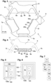
- the elastic holding member 1 for fixing a watch component 2 on a support element 3a, 3b.
- the elastic holding member 1 may be a collet for fixing the watch component 2 such as a hairspring to a support element 3a, 3b such as a “false axis” 3a and a balance shaft 3b visible respectively in the Figures 1 and 2 .
- This false axis 3a also called adjustment axis, false shaft or classification axis is specifically used in the context of adjusting a balance-spring assembly according to different known techniques such as the so-called omegametric technique consisting of carrying out a classification of the springs, a classification of the balances, a pairing of a balance chosen in a particular class, with a balance also chosen in a particular class, these classes being compatible with each other.
- omegametric technique consisting of carrying out a classification of the springs, a classification of the balances, a pairing of a balance chosen in a particular class, with a balance also chosen in a particular class, these classes being compatible with each other.
- balance shaft 3b it can also be called by its synonym balance shaft and is in particular designed to receive the collet.
- This elastic holding member 1 is made of a so-called “fragile” material, preferably a micro-machinable material.
- a material may comprise silicon, quartz, corundum, silicon and silicon dioxide, DLC, metallic glass, ceramic, other at least partially amorphous material, or the like.
- this holding member 1 can be included in an assembly 120 of elastic holding member - watch component visible in the Figures 5 and 6 .
- Such an assembly 120 is intended to be arranged in a clockwork movement 110 of a timepiece 100 visible in the figure 6 , and also to be driven onto a support element 3a such as the balance shaft or to be placed on a support element 3b such as the false axle when carrying out a sorting operation.
- Such an assembly 120 may be a single-piece part and be made of a “fragile” material similar to that of the ferrule.
- the elastic holding member 1 can be made of such a so-called “fragile” material, the timepiece component 2 then being made of another material.
- This assembly 120 may be part of an assembly 130a, 130b for the watch movement 110 or for a device 140 for carrying out a classification operation, by being mounted on the support element 3a, 3b, here the balance shaft or the false axis.
- a device 140 visible on the figure 5 includes in particular a measuring module 150 and the support element 3a here the false axis 3a.
- this assembly 130a, 130b was designed for applications in the watchmaking field. However, the invention can be perfectly implemented in other fields such as aeronautics, jewelry, or even the automobile industry.
- Such a holding member 1 comprises external and internal structures 4a, 4b as well as an upper face and a lower face 12 of preferably flat which are both respectively included in first and second planes P1 and P2.
- These external and internal structures 4a, 4b subsequently called external and internal peripheral walls 4a, 4b respectively delimit the external and internal contours of this holding member 1, the internal contour defining an opening 5 of this holding member.
- the external and internal peripheral walls 4a, 4b define different shapes of the holding member 1.
- This holding member 1 has a thickness which extends from the upper face to the lower face 12.
- this holding member 1 can correspond to any type of ferrule by comprising arms 6 each comprising an elastic sub-arm or rigid and elastic sub-arms 7a, 7b.
- each structural element 6 comprises a portion of the external and internal peripheral walls 4a, 4b as well as a portion of the upper and lower faces 12.
- These structural elements 6 are preferably solid. In other words, these structural elements 6 are preferably not hollow.
- the rigid sub-arms 7a and the elastic sub-arms 7b are subsequently called respectively first structural sub-elements 7a and second structural sub-elements 7b.
- the outer peripheral wall 4a of such a holding member 1 may have any shape, for example being essentially triangular, circular or a shape similar to that of a quadrilateral.
- the inner peripheral wall 4b of this holding member 1 helps to define the opening 5 of this holding member 1 in which the support element 3a, 3b is intended to be inserted.
- This opening 5 defines a volume in the holding member 1 which is less than that of a connecting part of one end of the support element 3a, 3b which is intended to be arranged there.
- this connecting part comprises in whole or in part portions 10 defined on the wall peripheral 21 of the support element 3a, 3b and which are provided in particular to cooperate with specific and/or dedicated first and second holding parts 20a, 20b of the structural elements 6.
- first and second holding parts 20a, 20b are each intended to ensure mounting of said holding member 1 on different support elements 3a, 3b here a balance shaft and a false axle.
- these first and second holding parts 20a, 20b each comprise at least one contact zone 8a, 8b configured to cooperate with the corresponding support element 3a, 3b.
- Each contact zone 8a, 8b of the first and second holding parts 20a, 20b is capable of cooperating with a corresponding contact portion 10 of the corresponding support element 3a, 3b while preferably being in a plano-convex type contact configuration.
- the external peripheral wall 4a it is in particular intended to be connected to the timepiece component 2 via at least one attachment point 11 arranged in the external peripheral wall of the holding member 1.
- a holding member 1 such as a ferrule illustrated in the Figures 1 to 4 , comprising structural elements 6 each comprising a first structural sub-element 7a and a second structural sub-element 7b.
- This holding member 1 comprises an internal surface 4b having a generally hexagonal shape comprising parts having convex shapes. Each of these parts is included in a connecting zone 9 connecting a second structural sub-element 7b to a first structural sub-element 7a.
- the internal peripheral wall 4b of this holding member 1 has a non-triangular shape.
- the connecting part comprises in whole or in part portions 10 defined on the peripheral wall 21 of the support element 3a, 3b and which are provided in particular to cooperate with specific and/or dedicated first and second holding parts 20a, 20b of the first structural sub-elements 7a.
- each first structural sub-element 7a comprises a connecting portion 19 provided with first and second holding parts 20a, 20b visible on the figure 4 And which are intended for mounting said holding member 1 respectively on support elements 3a, 3b each having a different cross section.
- this connecting portion 19 is also called “mounting portion 19” or “assembly portion 19”.
- first and second holding parts 20a, 20b which can also be called “mounting parts” or “assembly parts” or even “connecting parts”, are included in a connecting portion 19 of each first structural sub-element 7a, said portion 19 being included in the inner face of the holding member 1 by extending over all or part of the thickness of this holding member 1. In other words, each first and second holding part 20a, 20b therefore extends over all or part of the thickness of the holding member 1.
- the first and second holding portions 20a, 20b each comprise at least one contact zone 8a, 8b with the corresponding support element 3a, 3b.
- Each contact zone 8a, 8b may be rounded or convex or even flat.
- the contact zone 8a, 8b of each first and second holding portions 20a, 20b is capable of cooperating with the peripheral wall 21 of a connecting portion of the support element 3a, 3b, in particular with a corresponding contact portion 10 defined in this peripheral wall 21, while being in a plano-convex contact configuration.
- first structural sub-elements and these second structural sub-elements 7a, 7b connect the external and internal peripheral walls 4a, 4b of the holding member 1 to each other.
- these first and second structural and elastic sub-elements 7a, 7b essentially make it possible to produce an elastic clamping type coupling of the support element 3a, 3b in the opening 5 formed in this holding member 1 which is defined by the internal peripheral wall 4b of this holding member 1.
- these first structural sub-elements 7a therefore comprise only the contact zones 8a, 8b of the holding member. 1 with the support element 3a, 3b which can be defined in all or part of the connecting portion 19 of each first structural sub-element 7a.
- the first holding portion 20a comprises at least one contact zone 8a.
- This first holding portion 20a is intended to cooperate with the peripheral wall 21 of the support element 3a, for example here the false axis 3a.
- Such a support element 3a has a cross-section different from that of another support element 3b such as the balance shaft 3b whose peripheral wall is intended to cooperate only with the second holding portion 20b of each first structural sub-element 7a of the holding member 1.
- the difference(s) in this cross-section may relate to the shape of this section, in particular its geometric shape, but not exclusively.
- the section of this support element 3a is non-circular, preferably mainly triangular, being formed of three essentially flat faces.
- the flat faces of this support element 3a comprise the contact portions 10 of this element 3a, portions 10 which are therefore also flat.
- the connecting portion 19 of each first structural sub-element 7a comprises a substantially hollow or substantially concave part and two contact zones 8a defined at its ends and extending substantially over all or part of the thickness of the holding member 1. These two contact zones 8a are specifically defined so as to cooperate with the corresponding contact portions 10 included in the peripheral wall 21 of this support element 3a.
- Such contact zones 8a each have a surface preferably convex and delimit the ends of the connecting portion 19 of each first structural sub-element 7a.
- the convex surface of each of these contact zones 8a thus allows them to produce with the contact portions 10 a plano-convex type contact configuration. It should be noted here that the flat face of each contact portion 10 of the support element 3a is assessed relative to the convex surface of each corresponding contact zone 8a with respect to which this portion 10 is arranged.
- each first structural sub-element 7a makes it possible to produce a contact pressure between the holding member 1 and the support element 3a when producing a mechanical connection between them, while significantly reducing the intensity of the stresses at these contact zones 8a and the corresponding contact portions 10a of the support element 3a during the assembly and/or fixing of this holding member 1 with the support element 3a here the false axis, which stresses are likely to damage the holding member 1 by the appearance of breakages/fractures or even cracks.
- the second holding portion 20b also comprises at least one contact zone 8b.
- This second holding portion 20b is intended to cooperate with the peripheral wall 21 of a support element 3b such as the balance shaft 3b.
- a support element 3b has a cross-section different from that of another support element 3a such as the false axle 3a whose peripheral wall is intended to cooperate only with the first holding portion 20a of each first structural sub-element 7a of the holding member 1.
- the difference(s) in this cross section may (or may) relate to the shape of this section but not exclusively.
- the section of this support element 3b is preferably circular.
- the connecting portion 19 of each first structural sub-element 7a comprises a substantially hollow or substantially concave part in which two contact zones 8b are included. These two contact zones 8b are capable of cooperating with the corresponding contact portions 10 of the support element 3b.
- Such contact zones 8b are defined in the connecting portion 19, in particular in the concave part of this connecting portion 19, extending substantially over all or part of the thickness of the holding member 1.
- these contact zones 8b are flat, each comprising a surface which is wholly or partly flat.
- the two contact zones 8b of each first structural sub-element 7a are respectively included in different planes together forming an obtuse angle. These two contact zones 8b of each first structural sub-element 7a are disjointed by being spaced apart from each other.
- the connecting portion 19 comprises a separation zone 18 of the two contact zones 8b of each first structural sub-element 7a visible on the figure 4 .
- the contact zones 8b of the first structural sub-elements 7a are provided in particular to cooperate with the contact portions 10 according to a plano-convex type contact configuration in which configuration where the flat surface of each contact zone 8b cooperates with the corresponding convex-shaped contact portion 10 of the support element 3.
- this convex shape of each contact portion 10 is assessed relative to the flat surface of each corresponding contact zone 8b with respect to which this portion 10 is arranged.
- this flat surface of each contact zone 8b forms a plane tangent to the diameter of the support element. In other words, the flat surface is perpendicular to the diameter and therefore to the radius R1 of the support element.
- each first structural sub-element 7a makes it possible to apply contact pressure between the holding member 1 and the support element 3b when creating a mechanical connection between them, while significantly reducing the intensity of the stresses at these contact zones 8b and the corresponding contact portions 10 of the support element 3b when assembling and/or fixing this holding member 1 with the support element 3b, which stresses are likely to damage the holding member 1 by the appearance of breakages/fractures or even cracks.
- these two flat contact zones 8b are preferably distributed in a disjoint manner on the connecting portion 19 of each first structural sub-element 7a and this, between the two contact zones 8a of the first holding part 20a.
- the second holding part 20b comprises a single flat contact zone 8b included on the connecting portion 19 of each first structural sub-element 7a and this, equidistant from the two contact zones 8b of the first holding part 20a.
- the holding member 1 then comprises twelve contact zones 8a, 8b, six of which, referenced 8a, are configured to cooperate exclusively with a support element 3a, for example of the false axis 3a type, in the context of sorting operations, and six others with a support element 3b, for example of the balance shaft type, to achieve precise centering of the timepiece component 2, for example a hairspring, in the timepiece movement 110.
- each first structural sub-element 7a has a volume or quantity of material which is substantially greater or strictly greater than the volume or quantity of material constituting each second structural sub-element 7b.
- this gap E is a maximum gap E1 when it is defined between parts of internal and external peripheral walls included in each first structural sub-element 7a, i.e. the maximum gap E1 present between the inner and outer faces of this first structural sub-element 7a.
- this maximum gap E1 is defined between a portion of the outer peripheral wall of this first structural sub-element 7a and each contact zone 8a dedicated to cooperating with the peripheral wall 21 of the support element 3b such as the false axis, this contact zone 8a being included in the inner face of the inner peripheral wall of this first structural sub-element 7a. It will also be noted that this maximum gap E1 is greater than a gap E3 defined between a portion of the outer peripheral wall of the first structural sub-element 7a and each contact zone 8b dedicated to cooperating with the peripheral wall 21 of the support element 3b such as the balance shaft 3b, this contact zone 8b being included in the inner face of the inner peripheral wall 4b of this first structural sub-element 7a.
- this gap E is a minimum gap E2 when it is defined between parts of the external and internal peripheral walls 4a, 4b included in the second structural sub-elements 7b, i.e. the minimum gap E2 present between the internal and external faces of this second structural sub-element 7b.
- Such a minimum gap E2 is constant or substantially constant over the entire length over which these second structural sub-elements 7b extend. This length is here parallel or substantially parallel to the external and internal peripheral walls 4a, 4b included in these second structural sub-elements 7b.
- the gap E2 is in this holding member 1, less than the smallest gap defined in the first structural sub-element 7a. In other words, the gap E2 is the smallest gap which is defined between the external and internal peripheral walls 4a, 4b of this holding member 1.
- Such a configuration of the first structural sub-elements and the second structural sub-elements 7a, 7b allows the holding member 1 to store a greater quantity of elastic energy for a same tightening compared to the holding members of the state of the art.
- Such a quantity of elastic energy stored in the holding member 1 then makes it possible to obtain a greater holding torque of the holding member on the support element 3a, 3b in the assembly 130a, 130b of the assembly 120 holding member - watch component with this support element 3a, 3b.
- such a surplus of elastic energy stored in the holding member 1 therefore increases the holding torque and allows optimal elastic tightening.
- such a configuration of the holding member 1 makes it possible to store elastic energy ratios which are 6 to 8 times higher than those of the holding members of the state of the art.
- each second structural sub-element 7b makes it possible to accommodate the deformation of the entire holding member 1 with the geometry of the connecting part of the support element 3a, 3b on which it is assembled.
- the deformation mode undergone by each second structural sub-element 7b is a toroidal torsion coupled with a radial expansion.
- the invention also relates to a method for producing the assembly 130a, 130b of the assembly 120 elastic holding member - watch component with the support element 3a, 3b for example the balance shaft 3b or the false axis 3a.
- This method comprises a step 13 of mounting the support element 3a, 3b on the holding member 1.
- the support element 3a, 3b is inserted into the opening 5 of the holding member 1 more precisely the end of this support element 3a, 3b is presented at the entrance of this opening 5 defined by the internal peripheral wall 4b of the holding member 1 in anticipation of the introduction of the connecting part of this support element 3a, 3b into the volume defined in this opening 5.
- this step 13 comprises a sub-step of installation 14a during which the collet is put in place on this false axle 3a in preparation for example for carrying out the classification operation.
- This step 13 also comprises a sub-step of coupling 16a of this holding member 1 with the support element 3a here the false axle 3a.
- the coupling is carried out without elastic tightening and this, thanks to the complementarity of their shape which thus allows cooperation between the latter when they are driven in a rotational movement during the carrying out of the classification operation.
- this step 13 comprises a sub-step 14b of elastic deformation of the holding member 1 in particular of a central zone of this holding member 1 whose contour comprises said opening 5, which deformation results from the application of a contact force on the contact zones 8b of the first structural sub-elements 7a by the portions 10 of the peripheral wall 21 of the connecting part of the support element 3b.
- this elastic deformation of the holding member 1 results from the application of the contact force to the contact zones 8b of the first structural sub-elements 7a by the portions 10 of the peripheral wall 21 of the support element 3b.
- Such a deformation sub-sub-step 14b comprises a displacement phase 15 of the first structural sub-elements 7a under the action of the contact force applied to them.
- Such a movement of the first structural sub-elements 7a is carried out in a direction between a radial direction B1 relative to a central axis C common to the support element 3b and to the holding member 1, and a direction B2 coinciding with this central axis C.
- this direction B2 is perpendicular to the direction B1 and is oriented in a defined direction from the lower face 12 towards the upper face.
- the contact force is preferably perpendicular or substantially perpendicular to each contact zone 8b.
- a first deformation otherwise called " elastic torsional deformation" of these second structural sub-elements 7b is driven at its two ends in the same direction of rotation B4 by the first structural sub-elements 7a in displacement to which such ends are connected. It will be noted that only a portion of the body of these second structural sub-elements 7b is deformable in torsion here the ends of these second structural sub-elements 7b.
- Such a first deformation participates in particular in causing a deformation of each structural element 6 in torsion. This first deformation makes it possible to improve the insertion of the support element 3b into the opening 5 of the holding member 1 by participating in avoiding any breakage of the holding member 1 and/or any appearance of a crack in this member 1 during its assembly with the support element 3b.
- a second deformation otherwise called “ tensile deformation” or " elastic extension deformation " of the second structural sub-elements 7b is pulled at its two ends in the longitudinal direction B3 in opposite directions by the first structural sub-elements 7a in movement to which such ends are connected.
- Such a second deformation of the second structural sub-element 7b contributes in particular to each structural element 6 storing a significant amount of elastic energy.
- the holding member 1 also stores a significant amount of elastic energy
- This double elastic deformation of the second structural sub-elements 7b can be carried out simultaneously or substantially simultaneously, or even successively or substantially successively. It will be noted in the context of the implementation of this phase 15, when this double elastic deformation is carried out successively or substantially successively, the first deformation is then carried out before the second deformation.
- This assembly step 13 then comprises a sub-step 16b of fixing the holding member 1 on the support element 3b.
- a fixing sub-step 16b comprises a phase 17 of performing a radial elastic clamping of the holding member 1 on the support element 3b. It is therefore understood that in such a state of stress, the holding member 1 stores a significant quantity of elastic energy which contributes to giving it a substantial holding torque, in particular allowing optimal turning by elastic clamping.
Landscapes
- Physics & Mathematics (AREA)
- General Physics & Mathematics (AREA)
- Springs (AREA)
- Clamps And Clips (AREA)
- Connection Of Plates (AREA)
- Micromachines (AREA)
Claims (22)
- Elastisches Halteorgan (1) zum Fixieren einer Uhrmachereikomponente (2) auf Stützelementen (3a, 3b) mit unterschiedlichem Querschnitt, eine Öffnung (5) umfassend, in die jedes Stützelement (3a, 3b) eingeführt werden kann, wobei das Halteorgan (1) Strukturelemente (6) beinhaltet, die zusammen den Körper dieses Halteorgans (1) bilden und dazu beitragen, für eine Montage eines jeden Stützelements (3a, 3b) in der Öffnung (5) zu sorgen, wobei jedes dieser Strukturelemente (6) ein erstes Strukturteilelement (7a) und ein zweites Strukturteilelement (7b) umfasst, wobei das erste Strukturteilelement (7a) ein größeres Materialvolumen als das Materialvolumen beinhaltet aus dem das zweite Strukturteilelement (7b) besteht, das Halteorgan (1) einen Verbindungsabschnitt (19) umfasst, der für die Montage in dem Halteelement (1) eines jeden der Stützelemente (3a, 3b) sorgt, wobei der Abschnitt (19) auf einer Innenseite des ersten Strukturteilelements (7a) definiert ist, der Verbindungsabschnitt (19) ein erstes und ein zweites Halteteil (20a, 20b) umfasst, welche für die Montage in dem Halteelement (1) eines jeden der Stützelemente (3a, 3b) sorgen, dadurch gekennzeichnet, dass das zweite Halteteil (20b) zwei flache Kontaktbereiche (8b) umfasst, die getrennt auf einem Verbindungsabschnitt (19) jedes ersten Strukturteilelements (7a) zwischen den beiden Kontaktbereichen (8a) des ersten Halteteils (20a) verteilt sind.
- Elastisches Halteorgan (1) nach dem vorstehenden Anspruch, dadurch gekennzeichnet, dass der Verbindungsabschnitt (19) nur auf der Innenseite des ersten Strukturteilelements (7a) definiert ist.
- Elastisches Halteorgan (1) nach einem der vorstehenden Ansprüche, dadurch gekennzeichnet, dass das erste und zweite Halteteil (20a, 20b) jeweils mindestens einen Kontaktbereich (8a, 8b) umfassen, der konfiguriert ist, um mit dem entsprechenden Stützelement (3a, 3b) zusammenzuwirken.
- Elastisches Halteorgan (1) nach einem der vorstehenden Ansprüche, dadurch gekennzeichnet, dass mindestens ein Kontaktbereich (8a, 8b) des ersten und zweiten Halteteils (20a, 20b) im Verbindungsabschnitt (19) eines jeden ersten Strukturteilelements (7a) des Halteorgans (1) umfasst ist, der sich über die gesamte Dicke dieses Halteorgans (1) oder einen Teil davon erstreckt.
- Elastisches Halteorgan (1) nach dem vorstehenden Anspruch, dadurch gekennzeichnet, dass jeder Kontaktbereich (8a, 8b) des ersten und zweiten Halteteils (20a, 20b) imstande ist, mit einem entsprechenden Kontaktabschnitt (10) des entsprechenden Stützelements (3a, 3b) zusammenzuwirken, indem er sich in einer Kontaktkonfiguration vom plankonvexen Typ befindet.
- Elastisches Halteorgan (1) nach einem der Ansprüche 2 bis 5, dadurch gekennzeichnet, dass der erste Halteteil (20a) zwei konvexe Kontaktbereiche (8a) umfasst, die einen Verbindungsabschnitt (19) eines jeden ersten Strukturteilelements (7a) definieren.
- Elastisches Halteorgan (1) nach dem vorstehenden Anspruch, dadurch gekennzeichnet, dass die beiden flachen Kontaktbereiche (8b) des zweiten Halteteils (20b) eines jeden ersten Strukturteilelements (7a) jeweils in unterschiedlichen Ebenen liegen und zusammen einen stumpfen Winkel bilden.
- Elastisches Halteorgan (1) nach Anspruch 6, dadurch gekennzeichnet, dass das zweite Halteteil (20b) eines jeden ersten Strukturteilelements (7a) einen einzigen flachen Kontaktbereich (8b) umfasst, der in gleichem Abstand zu den beiden konvexen Kontaktbereichen (8a) des ersten Halteteils (20a) angeordnet ist.
- Elastisches Halteorgan (1) nach einem der vorstehenden Ansprüche, dadurch gekennzeichnet, dass es ebenso viele erste Strukturteilelemente (7a) wie zweite Strukturteilelemente (7b) umfasst.
- Elastisches Halteorgan (1) nach einem der vorstehenden Ansprüche, dadurch gekennzeichnet, dass die ersten Strukturteilelemente (7a) und die zweiten Strukturteilelemente (7b) nacheinander und abwechselnd im Halteorgan (1) angeordnet sind.
- Elastisches Halteorgan (1) nach einem der vorstehenden Ansprüche, dadurch gekennzeichnet, dass jedes erste Strukturteilelement (7a) an seinen beiden gegenüberliegenden Enden mit zwei zweiten unterschiedlichen Strukturteilelementen (7b) verbunden ist.
- Elastisches Halteorgan (1) nach einem der vorstehenden Ansprüche, dadurch gekennzeichnet, dass jedes zweite Strukturteilelement (7b) einen Querschnitt aufweist, der kleiner ist als der Querschnitt jedes ersten Strukturteilelements (7a).
- Elastisches Halteorgan (1) nach einem der vorstehenden Ansprüche, dadurch gekennzeichnet, dass jedes zweite Strukturteilelement (7b) einen Querschnitt aufweist, der über den gesamten Körper dieses zweiten Strukturteilelements (7b) hinweg konstant ist.
- Elastisches Halteorgan (1) nach einem der vorstehenden Ansprüche, dadurch gekennzeichnet, dass es einen Befestigungspunkt (11) für die Uhrmachereikomponente (2) umfasst.
- Elastisches Halteorgan (1) nach einem der vorstehenden Ansprüche, dadurch gekennzeichnet, dass es eine Spiralrolle zum Fixieren der Uhrmachereikomponente (2), wie einer Spirale, an einem Stützelement (3), wie einer Unruhwelle oder einer Dummy-Achse, ist.
- Elastisches Halteorgan (1) nach einem der vorstehenden Ansprüche, dadurch gekennzeichnet, dass es aus einem mikrobearbeitbaren Werkstoff hergestellt ist, das Silizium, Quarz, Korund, Silizium und Siliziumdioxid, DLC, metallisches Glas, Keramik oder einen anderen, zumindest teilweise amorphen Werkstoff, oder ähnliches umfasst.
- Baugruppe (120) aus elastischem Halteorgan - Uhrmachereikomponente (2) für ein Uhrwerk (110) eines Uhrmachereistücks (100), das ein Halteorgan (1) nach einem der vorstehenden Ansprüche umfasst.
- Baugruppe (120) nach dem vorstehenden Anspruch, dadurch gekennzeichnet, dass sie aus einem Stück gefertigt ist.
- Zusammenbau (130a), der eine elastische Baugruppe (120) aus elastischem Halteorgan - Uhrmachereikomponente nach einem der Ansprüche 17 und 18, und ein Stützelement (3a) umfasst, wobei die Baugruppe (120) auf dem Stützelement (3a) ab einem ersten Halteteil (20a) des Halteorgans (1) gehalten wird, wobei das erste Halteteil (20a) konfiguriert ist, um mit einer Umfangswand (21) des Stützelements (3a) zusammenzuwirken.
- Zusammenbau (130b), der eine Baugruppe (120) aus elastischem Halteorgan - Uhrmachereikomponente nach einem der Ansprüche 17 und 18 und ein Stützelement (3b) umfasst, wobei die Baugruppe (120) auf dem Stützelement (3b) ab einem zweiten Halteteil (20b) des Halteorgans (1) gehalten wird, wobei das zweite Halteteil (20b) konfiguriert ist, um mit einer Umfangswand (21) des Stützelements (3b) zusammenzuwirken.
- Uhrwerk (110), das mindestens einen Zusammenbau (130b) nach Anspruch 20 umfasst.
- Uhrmachereistück (100), das ein Uhrwerk (110) nach dem vorstehenden Anspruch umfasst.
Applications Claiming Priority (2)
| Application Number | Priority Date | Filing Date | Title |
|---|---|---|---|
| EP19167903.4A EP3722889A1 (de) | 2019-04-08 | 2019-04-08 | Elastisches halterungsorgan für die befestigung einer uhrkomponente auf verschiedenen halteelementen |
| PCT/EP2020/059815 WO2020207986A1 (fr) | 2019-04-08 | 2020-04-06 | Organe de maintien élastique pour la fixation d'un composant d'horlogerie sur des éléments de support differents |
Publications (2)
| Publication Number | Publication Date |
|---|---|
| EP3953769A1 EP3953769A1 (de) | 2022-02-16 |
| EP3953769B1 true EP3953769B1 (de) | 2025-01-08 |
Family
ID=66102546
Family Applications (2)
| Application Number | Title | Priority Date | Filing Date |
|---|---|---|---|
| EP19167903.4A Withdrawn EP3722889A1 (de) | 2019-04-08 | 2019-04-08 | Elastisches halterungsorgan für die befestigung einer uhrkomponente auf verschiedenen halteelementen |
| EP20715113.5A Active EP3953769B1 (de) | 2019-04-08 | 2020-04-06 | Elastisches halterungsorgan für die befestigung einer uhrkomponente auf verschiedenen halteelementen |
Family Applications Before (1)
| Application Number | Title | Priority Date | Filing Date |
|---|---|---|---|
| EP19167903.4A Withdrawn EP3722889A1 (de) | 2019-04-08 | 2019-04-08 | Elastisches halterungsorgan für die befestigung einer uhrkomponente auf verschiedenen halteelementen |
Country Status (6)
| Country | Link |
|---|---|
| US (1) | US12189338B2 (de) |
| EP (2) | EP3722889A1 (de) |
| JP (1) | JP7259079B2 (de) |
| KR (1) | KR102744960B1 (de) |
| CN (1) | CN113632014B (de) |
| WO (1) | WO2020207986A1 (de) |
Family Cites Families (15)
| Publication number | Priority date | Publication date | Assignee | Title |
|---|---|---|---|---|
| EP1445670A1 (de) | 2003-02-06 | 2004-08-11 | ETA SA Manufacture Horlogère Suisse | Spiralfeder der Resonatorunruh und Fabrikationsmethode |
| CH698837B1 (fr) * | 2003-02-06 | 2009-11-13 | Eta Sa Mft Horlogere Suisse | Spiral de résonateur balancier-spiral et son procédé de fabrication. |
| DE602006014280D1 (de) * | 2006-11-09 | 2010-06-24 | Eta Sa Mft Horlogere Suisse | Montageelement, das dehnbare Strukturen in Form von Gabeln umfasst, und dieses Element umfassende Uhr |
| EP1921518B1 (de) * | 2006-11-09 | 2010-05-26 | ETA SA Manufacture Horlogère Suisse | Montageelement, das dehnbare Strukturen in Form von aufeinander liegenden Plättchen umfasst, und mit diesem Element ausgerüstete Uhr |
| CH701783B1 (fr) * | 2009-09-07 | 2015-01-30 | Manuf Et Fabrique De Montres Et Chronomètres Ulysse Nardin Le Locle S A | Ressort spiral de mouvement de montre. |
| US9250610B2 (en) * | 2010-03-25 | 2016-02-02 | Rolex S.A. | Split collet with a non-circular opening |
| WO2013045706A2 (fr) | 2011-09-29 | 2013-04-04 | Rolex S.A. | Ensemble monolithique ressort spiral-virole |
| CH707288B1 (fr) * | 2012-11-22 | 2017-07-31 | Mft Et Fabrique De Montres Et De Chronomètres Ulysse Nardin Le Locle S A | Dispositif de maintien élastique de deux pièces. |
| EP2743782B1 (de) * | 2012-12-11 | 2016-02-03 | Nivarox-FAR S.A. | Vorrichtung zum zusammenbau von elastischen armen durch verformung |
| CH711213A2 (fr) * | 2015-06-16 | 2016-12-30 | Nivarox Far Sa | Pièce comportant une adaptation géométrique de la surface de contact à assembler par soudage avec un autre organe. |
| EP3309625B1 (de) * | 2016-10-13 | 2020-07-29 | Nivarox-FAR S.A. | Spirale zur befestigung mit einer federscheibe |
| JP6772790B2 (ja) * | 2016-11-29 | 2020-10-21 | セイコーエプソン株式会社 | 時計部品の製造方法、及び時計の製造方法 |
| EP3401740B1 (de) * | 2017-05-12 | 2021-03-31 | Patek Philippe SA Genève | Uhrkomponente zum einpressen ohne gratbildung |
| CH713999B1 (fr) * | 2017-07-18 | 2021-05-31 | Richemont Int Sa | Composant horloger destiné à être fixé sur un axe. |
| CH714000A1 (fr) * | 2017-07-18 | 2019-01-31 | Richemont Int Sa | Ensemble horloger comprenant un composant horloger fixé sur un axe. |
-
2019
- 2019-04-08 EP EP19167903.4A patent/EP3722889A1/de not_active Withdrawn
-
2020
- 2020-04-06 CN CN202080027341.1A patent/CN113632014B/zh active Active
- 2020-04-06 US US17/442,503 patent/US12189338B2/en active Active
- 2020-04-06 KR KR1020217031585A patent/KR102744960B1/ko active Active
- 2020-04-06 JP JP2021557529A patent/JP7259079B2/ja active Active
- 2020-04-06 EP EP20715113.5A patent/EP3953769B1/de active Active
- 2020-04-06 WO PCT/EP2020/059815 patent/WO2020207986A1/fr not_active Ceased
Also Published As
| Publication number | Publication date |
|---|---|
| WO2020207986A1 (fr) | 2020-10-15 |
| KR20210134367A (ko) | 2021-11-09 |
| EP3953769A1 (de) | 2022-02-16 |
| JP2022529407A (ja) | 2022-06-22 |
| EP3722889A1 (de) | 2020-10-14 |
| US12189338B2 (en) | 2025-01-07 |
| KR102744960B1 (ko) | 2024-12-19 |
| CN113632014B (zh) | 2026-04-10 |
| JP7259079B2 (ja) | 2023-04-17 |
| US20220155728A1 (en) | 2022-05-19 |
| CN113632014A (zh) | 2021-11-09 |
Similar Documents
| Publication | Publication Date | Title |
|---|---|---|
| EP2761380B1 (de) | Einteilige anordnung aus einer spiralfeder und spannzange | |
| EP2407831B1 (de) | Spirale für Unruh-Oszillator einer Uhr, und ihr Herstellungsverfahren | |
| EP3623876A1 (de) | Spiralrolle mit nicht kreisförmiger öffnung | |
| EP2796940A2 (de) | Uhrkomponente zur Aufnahme eines Organs durch Einpressen | |
| EP3853672B1 (de) | Elastisches halterungsorgan für die befestigung einer uhrenkomponente auf einem halteelement | |
| EP3953769B1 (de) | Elastisches halterungsorgan für die befestigung einer uhrkomponente auf verschiedenen halteelementen | |
| EP3779608A1 (de) | Elastisches halterungsorgan einer uhrenkomponente auf einem halteelement | |
| EP3786720B1 (de) | Uhrkomponente zur aufnahme eines organs durch einpressen | |
| EP3818416B1 (de) | Elastisches halterungsorgan für die befestigung einer uhrenkomponente auf einem halteelement | |
| EP3391154B1 (de) | Schwingsystem für eine uhr | |
| CH716046A2 (fr) | Organe de maintien élastique, tel qu'une virole, pour la fixation d'un composant d'horlogerie sur des éléments de support différents. | |
| EP3853671B1 (de) | Elastisches halterungsorgan für die befestigung einer uhrenkomponente auf einem halteelement | |
| CH715369B1 (fr) | Organe de maintien élastique pour la fixation d'un composant d'horlogerie sur un élément de support. | |
| EP4375762A1 (de) | Einteiliges befestigungselement für eine uhrkomponente auf einem trägerelement | |
| EP3853670B1 (de) | Elastisches halterungsorgan für die befestigung einer uhrenkomponente auf einem halteelement | |
| EP4375760A1 (de) | Befestigungselement für eine uhr | |
| CH720277A2 (fr) | Pièce monobloc d'attache d'un composant d'horlogerie sur un élément de support | |
| EP4375761A1 (de) | Elastisches halteelement zur befestigung einer uhrkomponente an einem trägerelement | |
| CH720280A2 (fr) | Elément de fixation pour l'horlogerie | |
| CH720279A2 (fr) | Organe de maintien élastique pour la fixation d'un composant d'horlogerie sur un élément de support | |
| WO2024074517A1 (fr) | Axe horloger | |
| CH715371A2 (fr) | Organe de maintien élastique pour la fixation d'un composant d'horlogerie sur un élément de support. | |
| CH715370A2 (fr) | Organe de maintien élastique pour la fixation d'un composant d'horlogerie sur un élément de support. | |
| CH715368A2 (fr) | Organe de maintien élastique pour la fixation d'un composant d'horlogerie sur un élément de support. |
Legal Events
| Date | Code | Title | Description |
|---|---|---|---|
| STAA | Information on the status of an ep patent application or granted ep patent |
Free format text: STATUS: UNKNOWN |
|
| STAA | Information on the status of an ep patent application or granted ep patent |
Free format text: STATUS: THE INTERNATIONAL PUBLICATION HAS BEEN MADE |
|
| PUAI | Public reference made under article 153(3) epc to a published international application that has entered the european phase |
Free format text: ORIGINAL CODE: 0009012 |
|
| STAA | Information on the status of an ep patent application or granted ep patent |
Free format text: STATUS: REQUEST FOR EXAMINATION WAS MADE |
|
| 17P | Request for examination filed |
Effective date: 20211108 |
|
| AK | Designated contracting states |
Kind code of ref document: A1 Designated state(s): AL AT BE BG CH CY CZ DE DK EE ES FI FR GB GR HR HU IE IS IT LI LT LU LV MC MK MT NL NO PL PT RO RS SE SI SK SM TR |
|
| DAV | Request for validation of the european patent (deleted) | ||
| DAX | Request for extension of the european patent (deleted) | ||
| P01 | Opt-out of the competence of the unified patent court (upc) registered |
Effective date: 20230611 |
|
| STAA | Information on the status of an ep patent application or granted ep patent |
Free format text: STATUS: EXAMINATION IS IN PROGRESS |
|
| 17Q | First examination report despatched |
Effective date: 20231122 |
|
| GRAP | Despatch of communication of intention to grant a patent |
Free format text: ORIGINAL CODE: EPIDOSNIGR1 |
|
| STAA | Information on the status of an ep patent application or granted ep patent |
Free format text: STATUS: GRANT OF PATENT IS INTENDED |
|
| INTG | Intention to grant announced |
Effective date: 20240927 |
|
| GRAS | Grant fee paid |
Free format text: ORIGINAL CODE: EPIDOSNIGR3 |
|
| GRAA | (expected) grant |
Free format text: ORIGINAL CODE: 0009210 |
|
| STAA | Information on the status of an ep patent application or granted ep patent |
Free format text: STATUS: THE PATENT HAS BEEN GRANTED |
|
| AK | Designated contracting states |
Kind code of ref document: B1 Designated state(s): AL AT BE BG CH CY CZ DE DK EE ES FI FR GB GR HR HU IE IS IT LI LT LU LV MC MK MT NL NO PL PT RO RS SE SI SK SM TR |
|
| REG | Reference to a national code |
Ref country code: GB Ref legal event code: FG4D Free format text: NOT ENGLISH |
|
| REG | Reference to a national code |
Ref country code: CH Ref legal event code: EP |
|
| REG | Reference to a national code |
Ref country code: DE Ref legal event code: R096 Ref document number: 602020044462 Country of ref document: DE |
|
| REG | Reference to a national code |
Ref country code: IE Ref legal event code: FG4D Free format text: LANGUAGE OF EP DOCUMENT: FRENCH |
|
| REG | Reference to a national code |
Ref country code: LT Ref legal event code: MG9D |
|
| REG | Reference to a national code |
Ref country code: NL Ref legal event code: MP Effective date: 20250108 |
|
| REG | Reference to a national code |
Ref country code: AT Ref legal event code: MK05 Ref document number: 1758737 Country of ref document: AT Kind code of ref document: T Effective date: 20250108 |
|
| PG25 | Lapsed in a contracting state [announced via postgrant information from national office to epo] |
Ref country code: NL Free format text: LAPSE BECAUSE OF FAILURE TO SUBMIT A TRANSLATION OF THE DESCRIPTION OR TO PAY THE FEE WITHIN THE PRESCRIBED TIME-LIMIT Effective date: 20250108 |
|
| PG25 | Lapsed in a contracting state [announced via postgrant information from national office to epo] |
Ref country code: RS Free format text: LAPSE BECAUSE OF FAILURE TO SUBMIT A TRANSLATION OF THE DESCRIPTION OR TO PAY THE FEE WITHIN THE PRESCRIBED TIME-LIMIT Effective date: 20250408 |
|
| PG25 | Lapsed in a contracting state [announced via postgrant information from national office to epo] |
Ref country code: FI Free format text: LAPSE BECAUSE OF FAILURE TO SUBMIT A TRANSLATION OF THE DESCRIPTION OR TO PAY THE FEE WITHIN THE PRESCRIBED TIME-LIMIT Effective date: 20250108 |
|
| PG25 | Lapsed in a contracting state [announced via postgrant information from national office to epo] |
Ref country code: PL Free format text: LAPSE BECAUSE OF FAILURE TO SUBMIT A TRANSLATION OF THE DESCRIPTION OR TO PAY THE FEE WITHIN THE PRESCRIBED TIME-LIMIT Effective date: 20250108 |
|
| PGFP | Annual fee paid to national office [announced via postgrant information from national office to epo] |
Ref country code: DE Payment date: 20250319 Year of fee payment: 6 |
|
| PG25 | Lapsed in a contracting state [announced via postgrant information from national office to epo] |
Ref country code: ES Free format text: LAPSE BECAUSE OF FAILURE TO SUBMIT A TRANSLATION OF THE DESCRIPTION OR TO PAY THE FEE WITHIN THE PRESCRIBED TIME-LIMIT Effective date: 20250108 |
|
| PG25 | Lapsed in a contracting state [announced via postgrant information from national office to epo] |
Ref country code: NO Free format text: LAPSE BECAUSE OF FAILURE TO SUBMIT A TRANSLATION OF THE DESCRIPTION OR TO PAY THE FEE WITHIN THE PRESCRIBED TIME-LIMIT Effective date: 20250408 Ref country code: IS Free format text: LAPSE BECAUSE OF FAILURE TO SUBMIT A TRANSLATION OF THE DESCRIPTION OR TO PAY THE FEE WITHIN THE PRESCRIBED TIME-LIMIT Effective date: 20250508 |
|
| PG25 | Lapsed in a contracting state [announced via postgrant information from national office to epo] |
Ref country code: HR Free format text: LAPSE BECAUSE OF FAILURE TO SUBMIT A TRANSLATION OF THE DESCRIPTION OR TO PAY THE FEE WITHIN THE PRESCRIBED TIME-LIMIT Effective date: 20250108 |
|
| PG25 | Lapsed in a contracting state [announced via postgrant information from national office to epo] |
Ref country code: PT Free format text: LAPSE BECAUSE OF FAILURE TO SUBMIT A TRANSLATION OF THE DESCRIPTION OR TO PAY THE FEE WITHIN THE PRESCRIBED TIME-LIMIT Effective date: 20250508 Ref country code: LV Free format text: LAPSE BECAUSE OF FAILURE TO SUBMIT A TRANSLATION OF THE DESCRIPTION OR TO PAY THE FEE WITHIN THE PRESCRIBED TIME-LIMIT Effective date: 20250108 |
|
| PG25 | Lapsed in a contracting state [announced via postgrant information from national office to epo] |
Ref country code: GR Free format text: LAPSE BECAUSE OF FAILURE TO SUBMIT A TRANSLATION OF THE DESCRIPTION OR TO PAY THE FEE WITHIN THE PRESCRIBED TIME-LIMIT Effective date: 20250409 Ref country code: BG Free format text: LAPSE BECAUSE OF FAILURE TO SUBMIT A TRANSLATION OF THE DESCRIPTION OR TO PAY THE FEE WITHIN THE PRESCRIBED TIME-LIMIT Effective date: 20250108 |
|
| PGFP | Annual fee paid to national office [announced via postgrant information from national office to epo] |
Ref country code: CH Payment date: 20250501 Year of fee payment: 6 |
|
| PG25 | Lapsed in a contracting state [announced via postgrant information from national office to epo] |
Ref country code: AT Free format text: LAPSE BECAUSE OF FAILURE TO SUBMIT A TRANSLATION OF THE DESCRIPTION OR TO PAY THE FEE WITHIN THE PRESCRIBED TIME-LIMIT Effective date: 20250108 |
|
| PG25 | Lapsed in a contracting state [announced via postgrant information from national office to epo] |
Ref country code: SE Free format text: LAPSE BECAUSE OF FAILURE TO SUBMIT A TRANSLATION OF THE DESCRIPTION OR TO PAY THE FEE WITHIN THE PRESCRIBED TIME-LIMIT Effective date: 20250108 |
|
| PG25 | Lapsed in a contracting state [announced via postgrant information from national office to epo] |
Ref country code: SM Free format text: LAPSE BECAUSE OF FAILURE TO SUBMIT A TRANSLATION OF THE DESCRIPTION OR TO PAY THE FEE WITHIN THE PRESCRIBED TIME-LIMIT Effective date: 20250108 |
|
| REG | Reference to a national code |
Ref country code: DE Ref legal event code: R097 Ref document number: 602020044462 Country of ref document: DE |
|
| PG25 | Lapsed in a contracting state [announced via postgrant information from national office to epo] |
Ref country code: DK Free format text: LAPSE BECAUSE OF FAILURE TO SUBMIT A TRANSLATION OF THE DESCRIPTION OR TO PAY THE FEE WITHIN THE PRESCRIBED TIME-LIMIT Effective date: 20250108 |
|
| PG25 | Lapsed in a contracting state [announced via postgrant information from national office to epo] |
Ref country code: EE Free format text: LAPSE BECAUSE OF FAILURE TO SUBMIT A TRANSLATION OF THE DESCRIPTION OR TO PAY THE FEE WITHIN THE PRESCRIBED TIME-LIMIT Effective date: 20250108 Ref country code: CZ Free format text: LAPSE BECAUSE OF FAILURE TO SUBMIT A TRANSLATION OF THE DESCRIPTION OR TO PAY THE FEE WITHIN THE PRESCRIBED TIME-LIMIT Effective date: 20250108 |
|
| PG25 | Lapsed in a contracting state [announced via postgrant information from national office to epo] |
Ref country code: RO Free format text: LAPSE BECAUSE OF FAILURE TO SUBMIT A TRANSLATION OF THE DESCRIPTION OR TO PAY THE FEE WITHIN THE PRESCRIBED TIME-LIMIT Effective date: 20250108 |
|
| PG25 | Lapsed in a contracting state [announced via postgrant information from national office to epo] |
Ref country code: SK Free format text: LAPSE BECAUSE OF FAILURE TO SUBMIT A TRANSLATION OF THE DESCRIPTION OR TO PAY THE FEE WITHIN THE PRESCRIBED TIME-LIMIT Effective date: 20250108 |
|
| PLBE | No opposition filed within time limit |
Free format text: ORIGINAL CODE: 0009261 |
|
| STAA | Information on the status of an ep patent application or granted ep patent |
Free format text: STATUS: NO OPPOSITION FILED WITHIN TIME LIMIT |
|
| PG25 | Lapsed in a contracting state [announced via postgrant information from national office to epo] |
Ref country code: LU Free format text: LAPSE BECAUSE OF NON-PAYMENT OF DUE FEES Effective date: 20250406 |
|
| 26N | No opposition filed |
Effective date: 20251009 |
|
| PG25 | Lapsed in a contracting state [announced via postgrant information from national office to epo] |
Ref country code: MC Free format text: LAPSE BECAUSE OF FAILURE TO SUBMIT A TRANSLATION OF THE DESCRIPTION OR TO PAY THE FEE WITHIN THE PRESCRIBED TIME-LIMIT Effective date: 20250108 |
|
| REG | Reference to a national code |
Ref country code: BE Ref legal event code: MM Effective date: 20250430 |
|
| PG25 | Lapsed in a contracting state [announced via postgrant information from national office to epo] |
Ref country code: BE Free format text: LAPSE BECAUSE OF NON-PAYMENT OF DUE FEES Effective date: 20250430 |
|
| PG25 | Lapsed in a contracting state [announced via postgrant information from national office to epo] |
Ref country code: IT Free format text: LAPSE BECAUSE OF FAILURE TO SUBMIT A TRANSLATION OF THE DESCRIPTION OR TO PAY THE FEE WITHIN THE PRESCRIBED TIME-LIMIT Effective date: 20250108 |
|
| PGFP | Annual fee paid to national office [announced via postgrant information from national office to epo] |
Ref country code: GB Payment date: 20260319 Year of fee payment: 7 |
|
| PG25 | Lapsed in a contracting state [announced via postgrant information from national office to epo] |
Ref country code: IE Free format text: LAPSE BECAUSE OF NON-PAYMENT OF DUE FEES Effective date: 20250406 |
|
| PGFP | Annual fee paid to national office [announced via postgrant information from national office to epo] |
Ref country code: FR Payment date: 20260320 Year of fee payment: 7 |