EP3853679B1 - Procédé d'analyse d'état d'un système électromécanique et système d'assemblage électromécanique destiné à la mise en uvre dudit procédé - Google Patents
Procédé d'analyse d'état d'un système électromécanique et système d'assemblage électromécanique destiné à la mise en uvre dudit procédé Download PDFInfo
- Publication number
- EP3853679B1 EP3853679B1 EP19765737.2A EP19765737A EP3853679B1 EP 3853679 B1 EP3853679 B1 EP 3853679B1 EP 19765737 A EP19765737 A EP 19765737A EP 3853679 B1 EP3853679 B1 EP 3853679B1
- Authority
- EP
- European Patent Office
- Prior art keywords
- zmw
- drive
- actual values
- additional measurement
- values
- Prior art date
- Legal status (The legal status is an assumption and is not a legal conclusion. Google has not performed a legal analysis and makes no representation as to the accuracy of the status listed.)
- Active
Links
Images


Classifications
-
- G—PHYSICS
- G05—CONTROLLING; REGULATING
- G05B—CONTROL OR REGULATING SYSTEMS IN GENERAL; FUNCTIONAL ELEMENTS OF SUCH SYSTEMS; MONITORING OR TESTING ARRANGEMENTS FOR SUCH SYSTEMS OR ELEMENTS
- G05B19/00—Program-control systems
- G05B19/02—Program-control systems electric
- G05B19/18—Numerical control [NC], i.e. automatically operating machines, in particular machine tools, e.g. in a manufacturing environment, so as to execute positioning, movement or co-ordinated operations by means of program data in numerical form
- G05B19/406—Numerical control [NC], i.e. automatically operating machines, in particular machine tools, e.g. in a manufacturing environment, so as to execute positioning, movement or co-ordinated operations by means of program data in numerical form characterised by monitoring or safety
- G05B19/4065—Monitoring tool breakage, life or condition
-
- G—PHYSICS
- G01—MEASURING; TESTING
- G01L—MEASURING FORCE, STRESS, TORQUE, WORK, MECHANICAL POWER, MECHANICAL EFFICIENCY, OR FLUID PRESSURE
- G01L5/00—Apparatus for, or methods of, measuring force, work, mechanical power, or torque, specially adapted for specific purposes
- G01L5/24—Apparatus for, or methods of, measuring force, work, mechanical power, or torque, specially adapted for specific purposes for determining value of torque or twisting moment for tightening a nut or other member which is similarly stressed
-
- G—PHYSICS
- G05—CONTROLLING; REGULATING
- G05B—CONTROL OR REGULATING SYSTEMS IN GENERAL; FUNCTIONAL ELEMENTS OF SUCH SYSTEMS; MONITORING OR TESTING ARRANGEMENTS FOR SUCH SYSTEMS OR ELEMENTS
- G05B23/00—Testing or monitoring of control systems or parts thereof
- G05B23/02—Electric testing or monitoring
- G05B23/0205—Electric testing or monitoring by means of a monitoring system capable of detecting and responding to faults
- G05B23/0259—Electric testing or monitoring by means of a monitoring system capable of detecting and responding to faults characterized by the response to fault detection
- G05B23/0264—Control of logging system, e.g. decision on which data to store; time-stamping measurements
-
- G—PHYSICS
- G05—CONTROLLING; REGULATING
- G05B—CONTROL OR REGULATING SYSTEMS IN GENERAL; FUNCTIONAL ELEMENTS OF SUCH SYSTEMS; MONITORING OR TESTING ARRANGEMENTS FOR SUCH SYSTEMS OR ELEMENTS
- G05B2219/00—Program-control systems
- G05B2219/30—Nc systems
- G05B2219/37—Measurements
- G05B2219/37252—Life of tool, service life, decay, wear estimation
-
- G—PHYSICS
- G05—CONTROLLING; REGULATING
- G05B—CONTROL OR REGULATING SYSTEMS IN GENERAL; FUNCTIONAL ELEMENTS OF SUCH SYSTEMS; MONITORING OR TESTING ARRANGEMENTS FOR SUCH SYSTEMS OR ELEMENTS
- G05B2219/00—Program-control systems
- G05B2219/30—Nc systems
- G05B2219/45—Nc applications
- G05B2219/45152—Forming workpiece by pressing tool against metal on model
-
- G—PHYSICS
- G05—CONTROLLING; REGULATING
- G05B—CONTROL OR REGULATING SYSTEMS IN GENERAL; FUNCTIONAL ELEMENTS OF SUCH SYSTEMS; MONITORING OR TESTING ARRANGEMENTS FOR SUCH SYSTEMS OR ELEMENTS
- G05B2219/00—Program-control systems
- G05B2219/30—Nc systems
- G05B2219/50—Machine tool, machine tool null till machine tool work handling
- G05B2219/50308—Estimate wear from machining data and conditions
Definitions
- the invention relates to a method for analyzing the condition of an electromechanical joining system.
- the invention also relates to an electromechanical joining system that is designed to carry out the method according to the invention.
- the known method is used, for example, in an electrical automation system and is used to monitor components subject to wear, such as a brake, a gear, a belt drive, a bearing, a screw drive, a guide, etc.
- the known method is used to detect emerging wear on the components mentioned at an early stage. This can, for example, enable the component in question to be replaced at a time when the failure of the electrical automation system is possible at minimized costs, for example during normal maintenance intervals. or during operational breaks of the electrical automation system.
- the method known from the document mentioned proposes using a monitoring device to process actual values of the electrical drive and, if necessary, additional measured values recorded by sensors. The measured values are processed using an algorithm and displayed, for example, on a suitable display unit.
- Electromechanical joining systems are used in automated joining processes.
- the electromechanical joining system has an electric drive with an electronically commutated servo motor and a screw drive.
- the screw drive converts a rotary motion of a drive shaft of the servo motor into a linear motion.
- the screw drive has a threaded spindle and a spindle nut.
- a plunger for tool holding is attached to one end of the spindle nut.
- the electromechanical joining system has components subject to wear such as a brake, a gear, a belt drive, the screw drive, bearings, a guide for the spindle nut, an anti-twisting device for the plunger, etc.
- the rotary motion of the drive shaft is recorded by an absolute encoder, which enables highly precise positioning of the plunger.
- a force sensor records the temporal progression of forces and torques acting during the joining processes.
- the WO2016205846A1 is directed to a method for determining a usage characteristic of a pressing tool in a joining press.
- the joining press has a usage duration timer that determines a usage time of the joining press.
- the joining press also has a force measuring device that determines a force effect of the joining press.
- the joining press also has an analysis and evaluation module that determines a tool service status from the usage time and the force effect.
- the object of the present invention is to reduce wear of components of an electromechanical joining system to be detected at an early stage in order to largely avoid failure of the electromechanical joining system.
- the invention relates to a method for analyzing the condition of an electromechanical joining system according to claim 1.
- the method according to the invention for the condition analysis of an electromechanical joining system with the features of claim 1 has the advantage that it enables the detection of impending wear of a component of the electromechanical joining system in a particularly simple manner.
- the teaching of the invention proposes determining the additional measured values required for the condition analysis by means of a sensor which is used to measure of temporal force or torque curves during the joining process, and that the algorithm of the control device links the actual values with the additional measured values.
- the algorithm of the control device links actual values of the electric drive (e.g. current intensity, angular speed of a drive shaft, etc.) with additional measured variables (force or torque) measured by the sensor in the electromechanical joining system.
- additional measured variables force or torque
- Such a link or such a quotient is also understood as the efficiency of the electromechanical joining system.
- a typical characteristic of impending wear of a component of the electromechanical joining system is that, for example, an increased current is required to achieve a certain value (force or torque) compared to a new or run-in state.
- a certain value force or torque
- this ratio can be interpreted and used as a warning message for impending wear or a necessary replacement of a component of the electromechanical joining system subject to wear.
- An electromechanical joining system within the meaning of the invention is basically understood to mean any device that is designed to effect a joining process.
- this also includes an electromechanical joining system for joining such as pressing, screwing, forming such as riveting, clinching, rolling, caulking, flanging, pressing or pressure joining of components.
- the actual values and the additional measured values are only taken into account by the algorithm during part of the duration of the joining process, wherein the actual values are preferably at least almost constant during the period taken into account.
- the background to this preferred variant is that, particularly at the beginning and end of the joining process, there are irregularities, for example in the power consumption of the electric drive or the angular speed of a drive shaft of the electric drive.
- the actual values of the electric drive are typically at least almost constant or do not have any peaks in a middle phase of the joining process.
- the algorithm should also make it possible to filter out or smooth out any irregularities that may exist during the period to be taken into account, so that these irregularities may not be taken into account. It is also conceivable, for example, during the to average or form a mean value for linearly changing measured values over the period of time taken into account.
- an alternative implementation of the method provides that the actual values and the additional measured values are taken into account by the algorithm during an additional operation outside the joining process, in particular during operation of the electromechanical joining system in which the electromechanical joining system is not subjected to force or torque.
- the actual values are values of a rotary movement of a drive shaft of the electric drive acting on the screw drive and/or actual values of the electric drive in the form of the current consumption of the electric drive. Both the rotary movement of the drive shaft and the current consumption of the electric drive can usually be monitored or determined using relatively simple sensors.
- control device creates or evaluates a temporal progression of the link between the actual values and the additional measured values.
- display means for example in the form of a graph on a screen or in numerical representation, make it possible to show a trend in terms of the linked measured values over the operating life of the electromechanical joining system.
- control device also extrapolates the temporal progression of the link between the actual values and the additional measured values for the future, i.e.
- Such a method makes it possible in particular to determine a (safe) remaining operating time of the electromechanical joining system until a worn component needs to be replaced or to draw conclusions about the possible service life of the corresponding component.
- control device can be arranged in the electric drive, or the control device can be arranged externally from the electric drive, for example in an external computer.
- control device is an integral part of a control device of the electric drive.
- the external computer can be arranged anywhere on earth. The actual values of the electric drive and the other measured values of the sensor can then be fed to the external computer as digital data via a network such as the Internet.
- the invention further comprises an electromechanical joining system with an electric drive which acts on a rotatable or linearly movable output element for a joining process by means of a screw drive.
- the electromechanical joining system is further characterized by first means for recording actual values of the electric drive and second means for recording further measured values of a sensor for measuring temporal force or torque curves during the joining process.
- the electromechanical joining system has a control device to which the actual values and the further measured values can be fed. Furthermore, the control device has an algorithm which is designed to calculate the actual values and the further To link measured values according to a method according to the invention as described so far.
- the electric drive is designed as a servo drive and that the servo drive has a control device for controlling the electric drive.
- Fig. 1 shows in perspective a part of an embodiment of an electric drive 10 of an electromechanical joining system 100 for joining two components.
- the electric drive 10 advantageously has a servo motor 12 and a brake 4.
- the main task of the brake 4 is to hold a plunger of the screw drive 20 in a position with high precision when the servo motor 12 is not energized.
- a further task of the brake 4 is to brake the servo motor 12.
- the servo motor 12 drives a drive shaft 18 via a gear 5 and a belt drive 6.
- the drive shaft 18 is supported by at least one bearing 7.
- the servo motor 12 rotates the drive shaft 18 at a speed n clockwise or anticlockwise.
- An absolute encoder 11 detects the speed n of the drive shaft 18.
- the absolute encoder 11 is preferably arranged spatially close to the brake 4 or the servo motor 12.
- Fig. 1 is the absolute value encoder 11 not shown figuratively.
- the servo motor can also drive the drive shaft without a gear or belt.
- the electric drive 10 has a screw drive 20.
- the screw drive 20 comprises a threaded spindle with a spindle nut, a guide 8 and an anti-twist device 9.
- the spindle nut sits on the threaded spindle.
- the threaded spindle has an external thread
- the spindle nut has an internal thread
- external thread and internal thread are cut to match each other.
- One end of the drive shaft 18 is connected to the threaded spindle in a rotationally fixed manner and rotates the threaded spindle.
- a rotational movement of the threaded spindle results in a linear movement of the threaded nut.
- the guide 9 guides the threaded nut during the linear movement.
- the plunger serves to hold the tool, in Fig. 1 Such a tool is not shown in the figure.
- the anti-twisting device 8 secures the plunger against twisting.
- FIG. 2 and 3 Two embodiments of an electromechanical joining system 100 for joining two components 1, 2 are shown schematically in a highly simplified manner.
- the electromechanical joining system 100 is to be used to press a first component 1 into an opening of a second component 2 in the direction of arrow 3 up to a certain position.
- the electromechanical joining system 100 has an electric drive 10 according to Fig. 1
- the electric Drive 10 is controlled by a control device 13.
- the electric drive 10 is a servo drive with a servo motor 12 and the control device 13 is a servo amplifier.
- the control device 13 is a computer.
- the control of the servo motor 12 by the control device 13 is in Fig. 2 and 3 marked by a double arrow.
- a housing of the electric drive 10 is in Fig. 2 and 3 shown in dashed lines.
- Servo motor 12, control device 13, drive shaft 18 and absolute encoder 11 are arranged in the housing.
- subject to wear means that, for example, the efficiency of the electromechanical joining system 100 is reduced over the service life of the electromechanical joining system 100 due to abrasion or increasing tolerances between components of the electromechanical joining system 100.
- the output element 22 mentioned is operatively connected to the first component 1 to be pressed into the component 2.
- the output element 22 is arranged in operative connection with a sensor 24.
- the sensor 24 serves to to determine a force or torque (depending on the type of joining process) applied by the output element 22 during the joining process of the component 1.
- the sensor 24 can be a strain gauge or a piezoelectric sensor.
- the sensor 24 can be integrated in the ram or attached to the ram.
- the value for the force or torque determined by the sensor 24 represents an additional measured value ZMW and is fed by the sensor 24 to a monitoring device 30 as an input variable.
- the person skilled in the art can also use a sensor to determine a pressure applied by the output element 22.
- At least one actual value IW, IW' of the electric drive 10 is supplied as an input variable by the control device 13 of the servo motor 12.
- An actual value IW is a rotational speed n of the drive shaft 18 or an actual value IW ⁇ is a required current I of the servo motor 12.
- Both the actual values IW, IW' of the electric drive 10 and the additional measured values ZMW of the sensor 24 are determined at the same time during the joining process and fed to the control device 14.
- a control device 14 is provided.
- the control device 14 is arranged in the electric drive 10.
- the control device 14 is an integral part of the control device 13.
- the control device 14 is designed as an external computer outside the electric drive 10.
- the control device 14 has an algorithm 16, which is designed to link the actual values IW, IW' of the electric drive 10 with the additional measured values ZMW of the sensor 24. The result of the link is used for a status analysis of the electromechanical joining system 100, which is used to detect impending wear and therefore impending failure or a required replacement of a component 21 subject to wear in a timely manner.
- the linking of the actual values IW, IW' of the electric drive 10 with the additional measured values ZMW of the sensor 24 preferably takes place in real time.
- real time is defined such that a result of the link is available in the control device 14 more quickly than the time it takes to supply the actual values IW, IW ⁇ of the electric drive 10 and the additional measured values ZMW of the sensor 24.
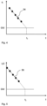
- FIG. 4 a diagram of the efficiency ⁇ over time t over a longer operating period of the electromechanical joining system 100 is shown.
- a curve 34 connects the individual points in time at which the corresponding actual values IW, IW' of the electric drive 10 and the additional measured values ZMW of the sensor 24 were fed to the control device 14.
- the algorithm 16 has determined a quotient between the actual values IW, IW ⁇ of the electric drive 10 and the additional measured values ZMW of the sensor 24 as the efficiency ⁇ at the respective points in time. Furthermore, an extrapolation for the future can be seen from the dashed time course of the curve 34.
- a limit value GW indicates a threshold at which it is worthwhile, for example from an economic point of view, to replace a worn component of the electromechanical joining system 100 due to the decreasing efficiency ⁇ or the looming wear of a component 21 subject to wear - before the wear leads to an unwanted interruption in the operation of the electromechanical joining system 100.
- the time t 1 at which the limit value GW will be reached can be extrapolated by the algorithm 16. The time t 1 is called the service life of the component 21 subject to wear.
- a curve 36 which represents the expected remaining service life LD of the electromechanical joining system 100 over time t.
- the actual values IW, IW' of the electric drive 10 and the additional measured values ZMW of the sensor 24 were used by means of the algorithm 16 using a service life formula, whereby the service life formula may include further factors or values which may have to be determined using further measured values or information.
- q i denotes the length of an operating period.
- n i represents an average speed measured during an operating period.
- F i is an average force measured during an operating period.
- LD 10 K 10 B ⁇ 1 3
- LD 5 K 5 B ⁇ 1 3
- K 10 and K 5 are experimentally determined proportionality factors.
- Time t 2 is called the service life of the electromechanical joining system 100.
- the curves 34, 36 shown can be displayed, for example, on a display device 30 connected to the control device 16, in particular a screen.
- the curve progressions 34, 36 or the numerical values resulting from the curve progressions 34, 36 as well as the underlying actual values of the electric drive 10 or the additional measured values of the sensor 24 can also be stored using a storage medium 32.
- the storage medium 32 is a Transducer Electronic Data Sheet (TEDS) according to the IEEE 1451.4 standard.
Landscapes
- Engineering & Computer Science (AREA)
- Physics & Mathematics (AREA)
- General Physics & Mathematics (AREA)
- Automation & Control Theory (AREA)
- Human Computer Interaction (AREA)
- Manufacturing & Machinery (AREA)
- Testing Of Devices, Machine Parts, Or Other Structures Thereof (AREA)
- Transmission Devices (AREA)
- Pressure Welding/Diffusion-Bonding (AREA)
- Press Drives And Press Lines (AREA)
- Numerical Control (AREA)
Claims (14)
- Procédé d'analyse de l'état d'un système d'assemblage électromécanique (100), dans lequel une force de sortie ou un couple de sortie pour un processus d'assemblage effectué par le système d'assemblage électromécanique (100) est généré par un entraînement électrique (10) au moyen d'un entraînement à vis (20) ; ledit entraînement (10) comprenant un servomoteur qui entraîne un arbre d'entraînement (18) par l'intermédiaire d'une transmission (5) et d'un entraînement par courroie (6) ; dans lequel des valeurs réelles (IW, IW') de l'entraînement électrique (10) sont fournies à un dispositif de commande (14) en tant que variable d'entrée, une valeur réelle (IW, IW') étant une vitesse de rotation (n) de l'arbre d'entraînement (18) ou un courant requis pour le servomoteur (12) ; dans lequel des valeurs de mesure supplémentaires (ZMW) sont déterminées par un capteur (24), lequel capteur (24) sert à mesurer l'évolution des forces ou des couples dans le temps au cours du processus d'assemblage ; dans lequel les valeurs de mesure supplémentaires (ZMW) sont fournies au dispositif de commande (14) en tant que variable d'entrée, dans lequel les valeurs réelles (IW, IW') de l'entraînement électrique (10) aussi bien que les valeurs de mesure supplémentaires (ZMW) du capteur (24) sont déterminées en même temps au cours du processus d'assemblage et alimentées au dispositif de commande (14) ; dans lequel le dispositif de commande (14) relie les valeurs réelles (IW, IW') aux valeurs de mesure supplémentaires (ZMW) au moyen d'un algorithme (16), dans lequel l'algorithme (16) calcule un rendement (η) à partir du quotient des valeurs réelles (IW, IW') par les valeurs de mesure supplémentaires (ZMW) ; et dans lequel le dispositif de commande (14) détecte une usure imminente d'un composant sujet à l'usure (21) du système d'assemblage électromécanique (100) à partir de cette relation.
- Procédé selon la revendication 1, caractérisé en ce que l'algorithme (16) n'utilise les valeurs réelles (IW, IW') et les valeurs de mesure supplémentaires (ZMW) que pendant une partie de la durée du processus d'assemblage, les valeurs réelles (IW, IW') étant de préférence au moins presque constantes au cours de la période considérée.
- Procédé selon la revendication 1, caractérisé en ce que l'algorithme (16) prend en compte les valeurs réelles (IW, IW') et les valeurs de mesure supplémentaires (ZMW) pendant une opération supplémentaire en dehors du processus d'assemblage, en particulier pendant une opération du système d'assemblage électromécanique (100) où aucune force ou aucun couple n'agit sur le système d'assemblage électromécanique (100).
- Procédé selon l'une quelconque des revendications 1 à 3, caractérisé en ce que l'algorithme (16) relie les valeurs réelles (IW, IW') et les valeurs de mesure supplémentaires (ZMW) qui sont transmises au dispositif de commande (14) à la même temps.
- Procédé selon l'une quelconque des revendications 1 à 4, caractérisé en ce que l'algorithme (16) prend en compte les valeurs réelles (IW, IW') et les valeurs de mesure supplémentaires (ZMW) pendant une vitesse angulaire de rotation constante de l'entraînement électrique (10).
- Procédé selon l'une quelconque des revendications 1 à 5, caractérisé en ce que l'algorithme (16) utilise des valeurs d'un mouvement de rotation d'un arbre d'entraînement (18) de l'entraînement électrique (20) agissant sur l'entraînement à vis (20) comme valeurs réelles (IW) ou l'algorithme (32) utilise des valeurs de la consommation d'énergie (I) d'un servomoteur (12) de l'entraînement électrique (10) comme valeurs réelles (IW').
- Procédé selon l'une quelconque des revendications 1 à 6, caractérisé en ce que le dispositif de commande (14) calcule une évolution temporelle de la relation entre les valeurs réelles (IW, IW') et les valeurs de mesure supplémentaires (ZMW).
- Procédé selon la revendication 7, caractérisé en ce que le dispositif de commande (14) extrapole dans le futur l'évolution temporelle de la relation entre les valeurs réelles (IW, IW') et les valeurs de mesure supplémentaires (ZMW).
- Procédé selon la revendication 7 ou 8, caractérisé en ce que le dispositif de commande (14) détermine respectivement le temps restant jusqu'à ce qu'au moins un composant sujet à l'usure (21) du système d'assemblage électromécanique (100) doive être remplacé ou une durée de vie (LD) du système d'assemblage électromécanique (100).
- Procédé selon l'une quelconque des revendications 7 à 9, caractérisé en ce que les résultats de la mise en relation de la liaison des valeurs réelles (IW, IW') avec les valeurs de mesure supplémentaires (ZMW) sont stockés dans un support de stockage (32) du système d'assemblage électromécanique (100).
- Système d'assemblage électromécanique (100) comprenant un entraînement électrique (10), lequel entraînement (120) agit sur un élément d'entraînement configuré pour être rotatif ou mobile linéairement (22) au moyen d'un entraînement à vis (20) pour effectuer un processus d'assemblage, ledit entraînement (10) comprenant un servomoteur (12), lequel servomoteur (12) entraîne un arbre d'entraînement (18) par l'intermédiaire d'une transmission (5) et d'un entraînement par courroie (6), comprenant des premiers moyens de détection des valeurs réelles (IW, IW') de l'entraînement électrique (10) et des seconds moyens de détection des valeurs de mesure supplémentaires (ZMW) au moyen d'un capteur (24) pour mesurer l'évolution des forces ou des couples dans le temps au cours du processus d'assemblage, dans lequel une valeur réelle (IW, IW') est une vitesse de rotation (n) de l'arbre d'entraînement (18) ou un courant requis pour le servomoteur (12), et comprenant un dispositif de commande (14) qui peut être alimenté par les valeurs réelles (IW, IW') et les valeurs de mesure supplémentaires (ZMW), dans lequel les premiers moyens détectent les valeurs réelles (IW, IW') de l'entraînement électrique (10) et les seconds moyens détectent les valeurs de mesure supplémentaires (ZMW) du capteur (24) à la même temps au cours du processus d'assemblage et les fournissent au dispositif de commande (14) ; dans lequel le dispositif de commande (14) comprend un algorithme (16) configuré pour relier les valeurs réelles (IW, IW') aux valeurs de mesure supplémentaires (ZMW) selon un procédé comme défini dans l'une quelconque des revendications 1 à 10, dans lequel l'algorithme (16) calcule un rendement (η) à partir du quotient des valeurs réelles (IW, IW') par les valeurs de mesure supplémentaires (ZMW) .
- Système d'assemblage électromécanique selon la revendication 11, caractérisé en ce qu'une unité de commande (13) contrôle l'entraînement électrique (10).
- Système d'assemblage électromécanique selon la revendication 11 ou 12, caractérisé en ce qu'un support de stockage (32) pour stocker les liaisons entre les valeurs réelles (IW, IW') et les valeurs de mesure supplémentaires (ZMW) effectuées par le dispositif de commande (14).
- Système d'assemblage électromécanique selon l'une quelconque des revendications 11 à 13, caractérisé en ce que le dispositif de commande (14) est disposé dans l'entraînement électrique (10) ou en ce que le dispositif de commande (14) est disposé en dehors de l'entraînement électrique (10).
Applications Claiming Priority (2)
| Application Number | Priority Date | Filing Date | Title |
|---|---|---|---|
| EP18195998 | 2018-09-21 | ||
| PCT/EP2019/074385 WO2020058087A1 (fr) | 2018-09-21 | 2019-09-12 | Procédé pour l'analyse d'état d'un système d'assemblage électromécanique et système d'assemblage électromécanique pour la mise en œuvre de ce procédé |
Publications (3)
| Publication Number | Publication Date |
|---|---|
| EP3853679A1 EP3853679A1 (fr) | 2021-07-28 |
| EP3853679B1 true EP3853679B1 (fr) | 2024-12-18 |
| EP3853679C0 EP3853679C0 (fr) | 2024-12-18 |
Family
ID=63713611
Family Applications (1)
| Application Number | Title | Priority Date | Filing Date |
|---|---|---|---|
| EP19765737.2A Active EP3853679B1 (fr) | 2018-09-21 | 2019-09-12 | Procédé d'analyse d'état d'un système électromécanique et système d'assemblage électromécanique destiné à la mise en uvre dudit procédé |
Country Status (6)
| Country | Link |
|---|---|
| US (1) | US11454948B2 (fr) |
| EP (1) | EP3853679B1 (fr) |
| JP (1) | JP7299310B2 (fr) |
| CN (1) | CN112771458B (fr) |
| ES (1) | ES3009024T3 (fr) |
| WO (1) | WO2020058087A1 (fr) |
Families Citing this family (2)
| Publication number | Priority date | Publication date | Assignee | Title |
|---|---|---|---|---|
| DE102020133452A1 (de) * | 2020-12-15 | 2022-06-15 | Audi Aktiengesellschaft | Verfahren zur Zustandsüberwachung eines Prozessgeräts, Computerprogramm, Vorrichtung zur Datenverarbeitung, computerlesbares Medium und Vorrichtung zur Zustandsüberwachung eines Prozessgeräts |
| DE102022110168B3 (de) * | 2022-04-27 | 2023-05-17 | Heidelberger Druckmaschinen Aktiengesellschaft | Funktionsüberwachung von Transportbändern in der Druckmaschine |
Family Cites Families (13)
| Publication number | Priority date | Publication date | Assignee | Title |
|---|---|---|---|---|
| JPH0724990B2 (ja) | 1990-11-09 | 1995-03-22 | 日東精工株式会社 | 自動ねじ締め装置 |
| JPH0537490U (ja) * | 1991-10-21 | 1993-05-21 | 株式会社不二越 | 産業用ロボツトの制御装置 |
| CN100445599C (zh) * | 2002-12-16 | 2008-12-24 | 盖茨公司 | 活动张紧器、控制皮带张力的系统和方法 |
| DE20305789U1 (de) | 2003-04-10 | 2003-06-26 | Dr. Staiger Mohilo + Co. GmbH, 73547 Lorch | Fügeeinheit |
| DE102004030076A1 (de) | 2004-06-22 | 2006-02-09 | Bosch Rexroth Aktiengesellschaft | Intelligenter Antrieb |
| JP2009039813A (ja) | 2007-08-08 | 2009-02-26 | Sintokogio Ltd | 圧入装置 |
| DE102007038890B4 (de) | 2007-08-17 | 2016-09-15 | Robert Bosch Gmbh | Verfahren und Vorrichtung zur Bestimmung der Lebensdauer von im Arbeitsbetrieb befindlichen Bauteilen |
| DE102014110507A1 (de) | 2014-07-25 | 2016-01-28 | Ief-Werner Gmbh | Pressverfahren mit Kompensation von Positionierfehlern bei einem Pressvorgang und Presse zur Durchführung eines solchen Verfahrens |
| US9996369B2 (en) | 2015-01-05 | 2018-06-12 | Anki, Inc. | Adaptive data analytics service |
| WO2016205846A1 (fr) | 2015-06-23 | 2016-12-29 | Henn Gmbh & Co Kg. | Procédé de détermination d'une caractéristique d'utilisation d'un outil de moulage par compression d'une presse d'assemblage |
| WO2017048788A1 (fr) * | 2015-09-14 | 2017-03-23 | Tolomatic, Inc. | Diagnostic et pronostic d'actionneur |
| CN105628377A (zh) * | 2015-12-25 | 2016-06-01 | 鼎奇(天津)主轴科技有限公司 | 一种主轴轴向静刚度测试方法及控制系统 |
| CN108536095B (zh) * | 2018-04-24 | 2020-01-17 | 湖北文理学院 | 一种丝杠磨损量实时预测方法 |
-
2019
- 2019-09-12 EP EP19765737.2A patent/EP3853679B1/fr active Active
- 2019-09-12 CN CN201980061955.9A patent/CN112771458B/zh active Active
- 2019-09-12 US US17/270,640 patent/US11454948B2/en active Active
- 2019-09-12 JP JP2021515563A patent/JP7299310B2/ja active Active
- 2019-09-12 ES ES19765737T patent/ES3009024T3/es active Active
- 2019-09-12 WO PCT/EP2019/074385 patent/WO2020058087A1/fr not_active Ceased
Also Published As
| Publication number | Publication date |
|---|---|
| JP7299310B2 (ja) | 2023-06-27 |
| CN112771458B (zh) | 2024-08-27 |
| CN112771458A (zh) | 2021-05-07 |
| WO2020058087A1 (fr) | 2020-03-26 |
| JP2022501723A (ja) | 2022-01-06 |
| ES3009024T3 (en) | 2025-03-25 |
| EP3853679C0 (fr) | 2024-12-18 |
| US11454948B2 (en) | 2022-09-27 |
| EP3853679A1 (fr) | 2021-07-28 |
| US20210365002A1 (en) | 2021-11-25 |
Similar Documents
| Publication | Publication Date | Title |
|---|---|---|
| DE102007038890B4 (de) | Verfahren und Vorrichtung zur Bestimmung der Lebensdauer von im Arbeitsbetrieb befindlichen Bauteilen | |
| DE2541928C3 (de) | Vorrichtung mit einem Meßgerät zum Anziehen einer Verbindung von Bauteilen, insbesondere einer Schraubverbindung | |
| DE4339117C2 (de) | Verfahren zur Überwachung des Setzvorgangs von Blindnieten und Blindnietmuttern und Setzgerät für Blindniete und Blindnietmuttern | |
| DE102022128423B3 (de) | Verfahren und ein Antriebsmodul zur Detektion, Quantifikation und Kompensation einer Eingriffsstörung eines Spannungswellengetriebes | |
| EP2549257B1 (fr) | Procédé de détection de dommages sur des engrenages | |
| EP0705156B1 (fr) | Procede permettant d'eviter que des contraintes excessives ne s'exercent sur une piece pendant le meulage | |
| EP3919781A1 (fr) | Module amélioré hélicoïdale et installation comprenant le module amélioré | |
| WO2012167987A1 (fr) | Procédé et dispositif de détection d'usure sur une bicyclette électrique | |
| EP1607192B1 (fr) | Méthode et système pour estimer l'usure des articulations d'un bras de robot | |
| DE102016006343A1 (de) | Mit einer funktion zum erkennen von anomalem bremsen ausgestattete motorsteuerung und verfahren zum erkennen von anomalem bremsen | |
| DE112015001924T5 (de) | Motorsteuereinrichtung | |
| EP3513911B2 (fr) | Machine de pressage | |
| EP1356211A1 (fr) | Procede et dispositif pour surveiller le fonctionnement d'un palier lisse | |
| WO2017016899A1 (fr) | Procédé et dispositif d'analyse du comportement à l'usure de garnitures de frein | |
| DE102016005214A1 (de) | Vorrichtung zum Überprüfen eines Zustandes eines Maschinenteils | |
| EP3727830B1 (fr) | Dispositif et procédé de surveillance d'un outil d'entraînement de clavette | |
| EP2048556A1 (fr) | Procédé de détermination de valeurs caractéristiques d'un axe suspendu et entraîné, en particulier d'une machine-outil, ainsi qu'applications appropriées, dispositifs correspondants et leur utilisation | |
| EP4245434A1 (fr) | Procédé de traction à chenilles et machine de traction à chenilles | |
| EP2118501B1 (fr) | Procédé de détermination automatique de l'état d'un groupe hydraulique | |
| EP3853679A1 (fr) | Procédé pour l'analyse d'état d'un système d'assemblage électromécanique et système d'assemblage électromécanique pour la mise en ?uvre de ce procédé | |
| DE102020117931B3 (de) | Verfahren und elektrischer Flugsteuerungsaktuator mit Einrichtungen zum Erfassen von Fehlern und Abnutzung des Flugsteuerungsaktuators | |
| DE102015225999A1 (de) | Verfahren zum Überprüfen des Zustandes eines Ventils | |
| EP1806837B1 (fr) | Méthode pour tester la fonction de freinage d'un entraînement du robot | |
| EP3313654B1 (fr) | Procédé de détermination d'une caractéristique d'utilisation d'un outil de moulage par compression d'une presse d'assemblage | |
| DE19923824C2 (de) | Verfahren und Vorrichtung zur Bestimmung von Belastungsdaten eines über einen Hydromotor angetriebenen Getriebes |
Legal Events
| Date | Code | Title | Description |
|---|---|---|---|
| STAA | Information on the status of an ep patent application or granted ep patent |
Free format text: STATUS: UNKNOWN |
|
| STAA | Information on the status of an ep patent application or granted ep patent |
Free format text: STATUS: THE INTERNATIONAL PUBLICATION HAS BEEN MADE |
|
| PUAI | Public reference made under article 153(3) epc to a published international application that has entered the european phase |
Free format text: ORIGINAL CODE: 0009012 |
|
| STAA | Information on the status of an ep patent application or granted ep patent |
Free format text: STATUS: REQUEST FOR EXAMINATION WAS MADE |
|
| 17P | Request for examination filed |
Effective date: 20210325 |
|
| AK | Designated contracting states |
Kind code of ref document: A1 Designated state(s): AL AT BE BG CH CY CZ DE DK EE ES FI FR GB GR HR HU IE IS IT LI LT LU LV MC MK MT NL NO PL PT RO RS SE SI SK SM TR |
|
| DAV | Request for validation of the european patent (deleted) | ||
| DAX | Request for extension of the european patent (deleted) | ||
| STAA | Information on the status of an ep patent application or granted ep patent |
Free format text: STATUS: EXAMINATION IS IN PROGRESS |
|
| 17Q | First examination report despatched |
Effective date: 20230519 |
|
| GRAP | Despatch of communication of intention to grant a patent |
Free format text: ORIGINAL CODE: EPIDOSNIGR1 |
|
| STAA | Information on the status of an ep patent application or granted ep patent |
Free format text: STATUS: GRANT OF PATENT IS INTENDED |
|
| INTG | Intention to grant announced |
Effective date: 20241002 |
|
| GRAS | Grant fee paid |
Free format text: ORIGINAL CODE: EPIDOSNIGR3 |
|
| GRAA | (expected) grant |
Free format text: ORIGINAL CODE: 0009210 |
|
| STAA | Information on the status of an ep patent application or granted ep patent |
Free format text: STATUS: THE PATENT HAS BEEN GRANTED |
|
| AK | Designated contracting states |
Kind code of ref document: B1 Designated state(s): AL AT BE BG CH CY CZ DE DK EE ES FI FR GB GR HR HU IE IS IT LI LT LU LV MC MK MT NL NO PL PT RO RS SE SI SK SM TR |
|
| REG | Reference to a national code |
Ref country code: CH Ref legal event code: EP |
|
| REG | Reference to a national code |
Ref country code: DE Ref legal event code: R096 Ref document number: 502019012669 Country of ref document: DE |
|
| REG | Reference to a national code |
Ref country code: IE Ref legal event code: FG4D Free format text: LANGUAGE OF EP DOCUMENT: GERMAN |
|
| U01 | Request for unitary effect filed |
Effective date: 20241218 |
|
| U07 | Unitary effect registered |
Designated state(s): AT BE BG DE DK EE FI FR IT LT LU LV MT NL PT RO SE SI Effective date: 20250102 |
|
| REG | Reference to a national code |
Ref country code: ES Ref legal event code: FG2A Ref document number: 3009024 Country of ref document: ES Kind code of ref document: T3 Effective date: 20250325 |
|
| PG25 | Lapsed in a contracting state [announced via postgrant information from national office to epo] |
Ref country code: HR Free format text: LAPSE BECAUSE OF FAILURE TO SUBMIT A TRANSLATION OF THE DESCRIPTION OR TO PAY THE FEE WITHIN THE PRESCRIBED TIME-LIMIT Effective date: 20241218 |
|
| PG25 | Lapsed in a contracting state [announced via postgrant information from national office to epo] |
Ref country code: NO Free format text: LAPSE BECAUSE OF FAILURE TO SUBMIT A TRANSLATION OF THE DESCRIPTION OR TO PAY THE FEE WITHIN THE PRESCRIBED TIME-LIMIT Effective date: 20250318 |
|
| PG25 | Lapsed in a contracting state [announced via postgrant information from national office to epo] |
Ref country code: GR Free format text: LAPSE BECAUSE OF FAILURE TO SUBMIT A TRANSLATION OF THE DESCRIPTION OR TO PAY THE FEE WITHIN THE PRESCRIBED TIME-LIMIT Effective date: 20250319 |
|
| PG25 | Lapsed in a contracting state [announced via postgrant information from national office to epo] |
Ref country code: RS Free format text: LAPSE BECAUSE OF FAILURE TO SUBMIT A TRANSLATION OF THE DESCRIPTION OR TO PAY THE FEE WITHIN THE PRESCRIBED TIME-LIMIT Effective date: 20250318 |
|
| PG25 | Lapsed in a contracting state [announced via postgrant information from national office to epo] |
Ref country code: SM Free format text: LAPSE BECAUSE OF FAILURE TO SUBMIT A TRANSLATION OF THE DESCRIPTION OR TO PAY THE FEE WITHIN THE PRESCRIBED TIME-LIMIT Effective date: 20241218 |
|
| PG25 | Lapsed in a contracting state [announced via postgrant information from national office to epo] |
Ref country code: PL Free format text: LAPSE BECAUSE OF FAILURE TO SUBMIT A TRANSLATION OF THE DESCRIPTION OR TO PAY THE FEE WITHIN THE PRESCRIBED TIME-LIMIT Effective date: 20241218 |
|
| PG25 | Lapsed in a contracting state [announced via postgrant information from national office to epo] |
Ref country code: IS Free format text: LAPSE BECAUSE OF FAILURE TO SUBMIT A TRANSLATION OF THE DESCRIPTION OR TO PAY THE FEE WITHIN THE PRESCRIBED TIME-LIMIT Effective date: 20250418 |
|
| PG25 | Lapsed in a contracting state [announced via postgrant information from national office to epo] |
Ref country code: SK Free format text: LAPSE BECAUSE OF FAILURE TO SUBMIT A TRANSLATION OF THE DESCRIPTION OR TO PAY THE FEE WITHIN THE PRESCRIBED TIME-LIMIT Effective date: 20241218 |
|
| PGFP | Annual fee paid to national office [announced via postgrant information from national office to epo] |
Ref country code: CZ Payment date: 20250904 Year of fee payment: 7 |
|
| PLBE | No opposition filed within time limit |
Free format text: ORIGINAL CODE: 0009261 |
|
| STAA | Information on the status of an ep patent application or granted ep patent |
Free format text: STATUS: NO OPPOSITION FILED WITHIN TIME LIMIT |
|
| REG | Reference to a national code |
Ref country code: CH Ref legal event code: L10 Free format text: ST27 STATUS EVENT CODE: U-0-0-L10-L00 (AS PROVIDED BY THE NATIONAL OFFICE) Effective date: 20251029 |
|
| U20 | Renewal fee for the european patent with unitary effect paid |
Year of fee payment: 7 Effective date: 20250924 |
|
| REG | Reference to a national code |
Ref country code: CH Ref legal event code: U11 Free format text: ST27 STATUS EVENT CODE: U-0-0-U10-U11 (AS PROVIDED BY THE NATIONAL OFFICE) Effective date: 20251106 |
|
| 26N | No opposition filed |
Effective date: 20250919 |
|
| PGFP | Annual fee paid to national office [announced via postgrant information from national office to epo] |
Ref country code: CH Payment date: 20251106 Year of fee payment: 7 |
|
| PGFP | Annual fee paid to national office [announced via postgrant information from national office to epo] |
Ref country code: ES Payment date: 20251030 Year of fee payment: 7 |