EP3853977B1 - Isoliervorrichtung mit kühlmediumleitung - Google Patents
Isoliervorrichtung mit kühlmediumleitung Download PDFInfo
- Publication number
- EP3853977B1 EP3853977B1 EP19758397.4A EP19758397A EP3853977B1 EP 3853977 B1 EP3853977 B1 EP 3853977B1 EP 19758397 A EP19758397 A EP 19758397A EP 3853977 B1 EP3853977 B1 EP 3853977B1
- Authority
- EP
- European Patent Office
- Prior art keywords
- insulating
- plastic material
- insulating body
- insulating device
- busbars
- Prior art date
- Legal status (The legal status is an assumption and is not a legal conclusion. Google has not performed a legal analysis and makes no representation as to the accuracy of the status listed.)
- Active
Links
Images




Classifications
-
- H—ELECTRICITY
- H02—GENERATION; CONVERSION OR DISTRIBUTION OF ELECTRIC POWER
- H02K—DYNAMO-ELECTRIC MACHINES
- H02K5/00—Casings; Enclosures; Supports
- H02K5/04—Casings or enclosures characterised by the shape, form or construction thereof
- H02K5/22—Auxiliary parts of casings not covered by groups H02K5/06-H02K5/20, e.g. shaped to form connection boxes or terminal boxes
-
- B—PERFORMING OPERATIONS; TRANSPORTING
- B60—VEHICLES IN GENERAL
- B60K—ARRANGEMENT OR MOUNTING OF PROPULSION UNITS OR OF TRANSMISSIONS IN VEHICLES; ARRANGEMENT OR MOUNTING OF PLURAL DIVERSE PRIME-MOVERS IN VEHICLES; AUXILIARY DRIVES FOR VEHICLES; INSTRUMENTATION OR DASHBOARDS FOR VEHICLES; ARRANGEMENTS IN CONNECTION WITH COOLING, AIR INTAKE, GAS EXHAUST OR FUEL SUPPLY OF PROPULSION UNITS IN VEHICLES
- B60K11/00—Arrangement in connection with cooling of propulsion units
- B60K11/02—Arrangement in connection with cooling of propulsion units with liquid cooling
-
- H—ELECTRICITY
- H02—GENERATION; CONVERSION OR DISTRIBUTION OF ELECTRIC POWER
- H02K—DYNAMO-ELECTRIC MACHINES
- H02K5/00—Casings; Enclosures; Supports
- H02K5/04—Casings or enclosures characterised by the shape, form or construction thereof
- H02K5/15—Mounting arrangements for bearing-shields or end plates
-
- H—ELECTRICITY
- H02—GENERATION; CONVERSION OR DISTRIBUTION OF ELECTRIC POWER
- H02K—DYNAMO-ELECTRIC MACHINES
- H02K5/00—Casings; Enclosures; Supports
- H02K5/04—Casings or enclosures characterised by the shape, form or construction thereof
- H02K5/20—Casings or enclosures characterised by the shape, form or construction thereof with channels or ducts for flow of cooling medium
-
- H—ELECTRICITY
- H02—GENERATION; CONVERSION OR DISTRIBUTION OF ELECTRIC POWER
- H02K—DYNAMO-ELECTRIC MACHINES
- H02K5/00—Casings; Enclosures; Supports
- H02K5/04—Casings or enclosures characterised by the shape, form or construction thereof
- H02K5/22—Auxiliary parts of casings not covered by groups H02K5/06-H02K5/20, e.g. shaped to form connection boxes or terminal boxes
- H02K5/225—Terminal boxes or connection arrangements
-
- H—ELECTRICITY
- H02—GENERATION; CONVERSION OR DISTRIBUTION OF ELECTRIC POWER
- H02K—DYNAMO-ELECTRIC MACHINES
- H02K9/00—Arrangements for cooling or ventilating
- H02K9/19—Arrangements for cooling or ventilating for machines with closed casing and closed-circuit cooling using a liquid cooling medium, e.g. oil
- H02K9/197—Arrangements for cooling or ventilating for machines with closed casing and closed-circuit cooling using a liquid cooling medium, e.g. oil in which the rotor or stator space is fluid-tight, e.g. to provide for different cooling media for rotor and stator
-
- H—ELECTRICITY
- H02—GENERATION; CONVERSION OR DISTRIBUTION OF ELECTRIC POWER
- H02K—DYNAMO-ELECTRIC MACHINES
- H02K5/00—Casings; Enclosures; Supports
- H02K5/04—Casings or enclosures characterised by the shape, form or construction thereof
- H02K5/20—Casings or enclosures characterised by the shape, form or construction thereof with channels or ducts for flow of cooling medium
- H02K5/203—Casings or enclosures characterised by the shape, form or construction thereof with channels or ducts for flow of cooling medium specially adapted for liquids, e.g. cooling jackets
Definitions
- the invention relates to an insulating device with a cooling medium line, which is used to dissipate waste heat from a stator of an electric machine.
- the invention relates to the use of the insulating device on an electric machine of a vehicle having at least one electric machine.
- the electric motor comprises a housing with a stator, a rotor and a rotary transformer.
- the rotary transformer has a primary-side first device with a primary winding and a secondary-side second device with a secondary winding.
- the housing has a first receptacle for positioning the primary-side first device.
- the primary-side first device comprises a number of first fastening points for non-positive and/or positive fastening to the housing.
- the rotor comprises a second receptacle for positioning the secondary-side second device, wherein the secondary-side second device has a number of second fastening points for non-positive and/or positive fastening to the rotor.
- the rotor contains a first connection device and the secondary-side second device contains a second connection device for electrically connecting the rotor to the secondary-side second device.
- the first connection device has first electrical contact elements and the second connection device has second electrical contact elements for detachable line connection by means of positive locking and/or frictional locking.
- the cooling system comprises at least one bearing plate and at least one coolant distribution plate, wherein the bearing plate and the coolant distribution plate are designed to jointly form a cooling channel.
- the cooling channel comprises a plurality of horizontal cooling channel sections which run parallel to an axis of rotation of the electrical machine. Furthermore, the cooling channel comprises a plurality of vertical cooling channel sections which run perpendicular to the axis of rotation of the electrical machine. Furthermore, a plurality of radially running cooling channel sections are provided which extend around the axis of rotation of the electrical machine.
- DE 11 2012 002 552 T5 refers to an electric motor.
- the electric motor includes a shaft provided with a rotor having a coolant passageway formed therein so that a cooling medium can flow therethrough. Furthermore, a housing is provided in which the shaft is provided, the shaft being rotatably supported. There is provided a cooling medium supply section which extends inside the housing on a side of one end of the shaft and supplies the cooling medium to the inner cooling medium passageway. There is further provided a rotation angle detection sensor which is attached to the side of one end of the shaft and detects a rotation angle of the shaft.
- US 2018 002 6493 A1 refers to a housing for an electric motor.
- a housing for an electric motor includes a housing body having an inner part and an outer part, which together form a cooling medium path extending in the axial direction of the housing body.
- a power component portion protruding from the outer surface of the outer housing part is formed such that the power component is cooled by the cooling medium.
- Housing covers are arranged at both end portions of the housing body so that the electric machine and the power component are simultaneously cooled via the one cooling fluid flow path. This allows a separate power component housing for arranging the power component can be avoided, thereby reducing the size and weight of the housing.
- US 3,808,489 refers to a cooled cover of a generator connection section.
- the connection section for high-voltage connections of a dynamo-electric machine is provided with special arresters to prevent overheating of the connection area walls due to circulating currents emanating from the high-voltage connections.
- the shields and the connection area are cooled by a gas which flows between them through suitable channels.
- US 5,814,909 refers to an electric motor that includes a heat radiator at an electrical connection to an inverter.
- the coils of the electric motor are electrically connected to power electronics of an inverter.
- a line section that provides a driving current to the motor coils includes a first heat radiation region or another heat radiation element within the line path. In this way, the heat generated by the electric motor is conducted from the line section into the line path.
- the power device and other components of the inverter can thereby be protected from thermally induced damage or from weathering phenomena caused by the heat generated by the motor coils and conducted to the inverter through the line section that has a higher thermal conductivity.
- JP 04 265 614 A refers to phase isolation with forced air cooling.
- the (three-phase) electric motors used on electric drive axles require an electrical connection of the stator phases in order to operate. If longer distances have to be overcome to the control electronics, the phase currents are guided via copper busbars. These busbars have a relatively large cross-section in order to keep the ohmic resistance and heating as low as possible. In order to maintain the required clearance and creepage distances, the busbars are held in a plastic insulating piece.
- the stator of the electric machine is often water-cooled to dissipate the waste heat.
- the cooling water is supplied and discharged in the area of the bearing plate, for example.
- the cooling water is fed between these connection points to absorb heat in the machine housing. Since the connection of the internal cooling water supply and the desired connection direction of the cooling water hoses often requires unfavorably curved supply lines, which are very complex to produce using casting technology, they are usually formed with attached pipes made of plastic or metal.
- an insulating device with integrated cooling medium channels which comprises an insulating body made of a plastic material in which busbars are accommodated.
- the cooling medium channels are integrated into the plastic material of the cooling body.
- the insulating device can be designed either in a one-piece design or in a multi-piece design.
- the integrated cooling medium channels are molded in the area of the front side of the insulating body of the insulating device proposed according to the invention.
- the molding of the cooling medium channels from the plastic material from which the insulating body is made can be carried out in can be manufactured particularly easily using the injection molding process of a plastic material.
- the cooling medium channels on the insulating body of the insulating device run in such a way that they extend essentially in the vertical direction.
- the busbars which are embedded in the insulating body can advantageously be insulated from one another and pipe bends in which the cooling medium flows can be integrated into the insulating body of the insulating device.
- the insulating body of the insulating device proposed according to the invention is made of an electrically insulating plastic material that is optimized for the best possible heat conduction. This is, for example, a plastic material such as Luvocom 1-8259 or Tecacomp PA 66 TC 3923.
- the solution proposed according to the invention advantageously avoids the production of complicated cooling medium channels through mold cores or intersecting holes, without the need for additional components such as separate connection pieces and the like.
- the solution proposed according to the invention enables particularly space-saving and simple cooling of the busbars, so that the ohmic resistance and the heating of the same under high loads remain as low as possible.
- the insulating device proposed according to the invention can be designed either in a one-piece design or in a multi-piece design.
- the individual parts of the insulating body can be made from different plastic materials.
- the parts of the insulating body - in the case of a multi-piece design - lie against one another along a parting line, with a first part of the insulating body in the case of a multi-piece design for example, two busbars are arranged and only one busbar is arranged in a second part of the insulating body that is complementary to this, or vice versa.
- this can advantageously be made of one material, wherein in particular the integrated cooling medium channels are injection-molded onto the front side of the insulating device.
- busbars that are flat-designed, punched from sheet metal or otherwise formed
- wires in various designs can also be used.
- a solid wire with a round or other cross-section can be used, as well as twisted or braided strands.
- the corresponding receiving geometry in the material of the insulating body is complementary to the geometry of the busbar used.
- the thermal coupling of the conductors to the plastic surface of the insulating body can be improved by using thermal paste, which applies both to the use of busbars in flat design and to the use of busbars in wire form - as explained above.
- the invention further relates to the use of the insulating device with integrated cooling medium channels for cooling an electric motor of a vehicle having at least one electric motor, be it an electric vehicle (EV), a hybrid electric vehicle (HEV) or a plug-in hybrid electric vehicle (PHEV).
- a vehicle having at least one electric motor be it an electric vehicle (EV), a hybrid electric vehicle (HEV) or a plug-in hybrid electric vehicle (PHEV).
- EV electric vehicle
- HEV hybrid electric vehicle
- PHEV plug-in hybrid electric vehicle
- the cooling medium circuit of the internal combustion engine can advantageously also be used at the same time to cool the at least one electric motor of a hybrid electric vehicle, without a separate cooling medium circuit being required in a hybrid electric vehicle.
- the solution proposed according to the invention advantageously offers a way of simplifying the manufacture of housing parts for electric machines, since the solution proposed according to the invention can avoid the production of complicated cooling medium channels through mold cores on cast parts or intersecting holes on cast parts, without the need for additional components such as separate connection pieces or the like.
- the solution proposed according to the invention allows the busbars guided in the insulating body of the insulating device to be cooled very easily and efficiently and kept at a low temperature value that advantageously promotes the ohmic resistance.
- the solution proposed according to the invention can achieve a considerable reduction in the effort that would otherwise have to be made with regard to the cooling medium guidance.
- the insulating device proposed according to the invention with integrated cooling medium channels can reduce the temperature level in the area of the busbars on the insulating body; furthermore, the solution proposed according to the invention can in particular achieve efficient and reliable electrical insulation of the busbars from one another. In contrast to previously used solutions using pipe bends and the like, which have to be subsequently insulated, the solution proposed according to the invention can reduce the number of components, save on seals and, in particular, ensure leak-free cooling medium guidance.
- the solution proposed according to the invention is characterized by a weight saving, compared to a solution in which the entire channel guide runs in a bearing plate made of aluminum and this has to be dimensioned accordingly larger.
- FIG. 1 The representation in Figure 1 is a perspective view of an e-axis module.
- FIG. 1 shows a side perspective view of an electric axle module, in particular showing a bearing plate 12 of a housing. Above the bearing plate 12, which largely covers an electric machine 14, a part of a power electronics 10 is shown. On the power electronics 10, Figure 1 not shown electrical connections are included, via which the Figure 1 not shown electric machine 14 is supplied with power. Phase connections extend from the electric machine 14 16 each to a first busbar 18, a second busbar 20 and a third busbar 22.
- a cooling medium guide 24 comprises a pipe bend 26. This is, for example, an inlet 28 for a cooling medium, while the in Figure 1
- the return line 30, also shown in perspective view, serves to return the cooling medium.
- Figure 2 shows a perspective view of an insulating piece 32.
- the insulating piece is surrounded by a border and comprises individual insulating webs 34, by which the first busbar 18 is separated from the second busbar 20 and the second busbar 20 is separated from the third busbar 22.
- the insulating piece 32 has an insulating piece trough 36, which is surrounded by the border.
- the insulating pieces 34 extending through the insulating piece 32 insulate the first busbar 18, the second busbar 20 and the third busbar 22 from one another.
- Figure 3 shows a perspective view of a pipe bend 26, which is made, for example, of a metallic material and which conducts cooling medium to the bearing plate 12 on which the electric motor is mounted.
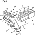
- Figure 4 shows a first embodiment of the insulating device proposed according to the invention with integrated cooling medium channels.
- an insulating body 74 in which the first busbar 18, the second busbar 20 and the third busbar 22 are accommodated in an insulated manner from one another, is made, for example, of a first plastic material 52.
- an insulating body 74 which is made from a first plastic material 52.
- the plastic injection molding process is preferably used to manufacture the insulating body 74 with regard to the first channel 44 and the second channel 46.
- the first plastic material 52 is, for example, an electrically insulating plastic material optimized for the best possible heat conduction, such as Luvocom 1-8259 or Tecacomp PA 66 TC 3923.
- the insulating body 74 of the insulating device 40 is designed in a one-piece design 50.
- the insulating body 74 is preferably manufactured in one operation as part of the plastic injection molding process.
- the respective insulating webs 34 surrounded by a border 48 can also be manufactured during plastic injection molding.
- the insulating webs 34 which run through the interior of the insulating body 74, electrically insulate the first busbar 18 from the second busbar 20 and the second busbar 20 from the third busbar 22.
- the first, second and third busbars 18, 20, 22 each comprise connection areas 72, which can be provided with a circular opening or the like, for example.
- first channel 44 and the second channel 46 extend essentially in the vertical direction 76 on the front side 42 of the insulating body 74.
- an inflow 54 is placed in the area in which more heat is to be dissipated because, for example, several busbars 18, 20, 22 are arranged there or the busbars 18, 20 and 22 arranged there are longer because the effectiveness is greater in these due to the low coolant temperature.
- the first busbar 18, the second busbar 20 and the third busbar 22 are shaped such that they have sections that run flat in relation to the bottom of the insulating body 74 as well as sections that run edgewise and are rotated by 90° thereto.
- FIG. 5 1 shows a perspective top view of an insulating body 74 which is designed in a multi-part design 59.
- the insulating device 40 proposed according to the invention comprises a first part 64 and a second part 66. While in the embodiment according to Figure 5 the first part 64 accommodates the first busbar 18 and the second busbar 20, the second part 66 only accommodates the third busbar 22.
- the orientation of the connection areas 72 of the busbars 18, 20 and 22 changes in the multi-part version 58 according to Figure 5 Compared to the one-piece version 50 according to Figure 4 nothing.
- the second part 66 of the insulating body 74 could be injection molded from the first plastic material 52 as shown in Figure 5 from a different, second plastic material 60. Both parts, the first part 64 and the second part 66, have in common that the first channel 44 and the second channel 46 are molded onto their parallel end faces 42. With respect to the first part 64, the first channel 44 is located on the end face 42. The second part 66 of the insulating device 40, on the other hand, accommodates the second channel 46 on its end face 42.
- the two channels 44, 46 on the first part 64 and the second part 66 also run essentially in the vertical direction 76 on the front side 42 of the two parts 64 and 66 lying next to one another along a parting line 62.
- the injection molding tool in which the first plastic material 52 or the second plastic material 60 are processed can be designed more simply.
- Figure 5 illustrated multi-part design 58 leakage tolerances can be simplified if the insulating body 74 is designed in two parts, with a first channel 44 provided on the first part 64 and a second channel 46 provided on the second part 66.
- a first part 64 of the insulating body 74 can be removed in a multi-part design.
- the first channel 44 runs essentially in the vertical direction 76 on the front side 42.
- the first channel 44 can be flowed through by both an inflow 54 and an outflow 56 of a cooling medium.
- the inflow 54 is preferably located in the area in which more heat is generated, for example if several busbars 18, 20, 22 are arranged there and these are designed to be longer.
- the first part 64 of the insulating body 74 accommodates the first busbar 18 or the second busbar 20, which are connected by a Figure 5
- the first busbar 18 and the second busbar 20 each have the connection areas 72 at their ends.
- a bottom section of the first part 64 of the insulating device 40 is shown in the illustration according to Figure 6 identified with reference numeral 68.
- the first part 64 comprises a recess 70 so that the phase connections 16, compare illustration according to Figure 1 , the electric machine 14 can be more easily connected to the connection areas 72 of the first busbar 18 and the second busbar 20.
- the busbars 18, 20 and 22 are shown in the illustrations according to the Figures 4 and 5 and 6 are generally partially embedded as inserted parts in the respective insulating body 74 or in the first part 64 and its second part 66.
- a thermal paste can also be provided.
- the busbars 18, 20 and 22 described above can also be designed as wires, for example as solid wires with a round or other cross-section, as laid strands or even as braided strands. If such geometries are selected for the busbars 18, 20, 22, the receiving geometry in the insulating body 74 is accordingly not flat, but for example semi-circular, in any case complementary to the geometry of the busbars 18, 20 and 22 that are not designed in a flat design. Furthermore, thermal paste can be used to improve the thermal coupling of the busbars 18, 20, 22 - whether they are designed in a flat design or as wires - to the plastic material of the insulating body 74.
Landscapes
- Engineering & Computer Science (AREA)
- Power Engineering (AREA)
- Chemical & Material Sciences (AREA)
- Combustion & Propulsion (AREA)
- Transportation (AREA)
- Mechanical Engineering (AREA)
- Injection Moulding Of Plastics Or The Like (AREA)
- Cooling Or The Like Of Electrical Apparatus (AREA)
- Motor Or Generator Cooling System (AREA)
Description
- Die Erfindung bezieht sich auf eine Isoliervorrichtung mit Kühlmediumleitung, die zur Abführung von Verlustwärme eines Stators einer E-Maschine eingesetzt wird.
- Des Weiteren bezieht sich die Erfindung auf die Verwendung der Isoliervorrichtung an einer E-Maschine eines mindestens eine E-Maschine aufweisenden Fahrzeugs.
-
DE 10 2012 021 600 A1 bezieht sich auf einen Elektromotor. Der Elektromotor umfasst ein Gehäuse, mit einem Stator, einem Rotor und einem Drehübertrager. Der Drehübertrager weist eine primärseitige erste Vorrichtung mit einer Primärwicklung und eine sekundärseitige zweite Vorrichtung mit einer Sekundärwicklung auf. Das Gehäuse weist eine erste Aufnahme zur Positionierung der primärseitigen ersten Vorrichtung auf. Die primärseitige erste Vorrichtung umfasst eine Anzahl erster Befestigungsstellen zur kraftschlüssigen und/oder formschlüssigen Befestigung am Gehäuse. Der Rotor umfasst eine zweite Aufnahme zur Positionierung der sekundärseitigen zweiten Vorrichtung, wobei die sekundärseitige zweite Vorrichtung eine Anzahl zweiter Befestigungsstellen zur kraftschlüssigen und/oder formschlüssigen Befestigung an dem Rotor aufweist. Der Rotor enthält eine erste Anschlussvorrichtung und die sekundärseitige zweite Vorrichtung eine zweite Anschlussvorrichtung zur elektrischen Verbindung des Rotors mit der sekundärseitigen zweiten Vorrichtung. Die erste Anschlussvorrichtung weist erste elektrische Kontaktglieder und die zweite Anschlussvorrichtung zweite elektrische Kontaktglieder zur lösbaren Leitungsverbindung mittels Formschluss und/oder Kraftschluss. -
DE 10 2015 216 055 A1 bezieht sich auf das Kühlsystem einer elektrischen Maschine. Das Kühlsystem umfasst mindestens einen Lagerschild und wenigstens eine Kühlmittelverteilerplatte, wobei der Lagerschild und die Kühlmittelverteilerplatte dazu eingerichtet sind, gemeinsam einen Kühlkanal auszubilden. Der Kühlkanal umfasst mehrere horizontale Kühlkanalabschnitte, welche parallel zu einer Drehachse der elektrischen Maschine verlaufen. Ferner umfasst der Kühlkanal mehrere vertikale Kühlkanalabschnitte, welche senkrecht zur Drehachse der elektrischen Maschine verlaufen. Ferner sind mehrere radial verlaufende Kühlkanalabschnitte vorgesehen, welche sich um die Drehachse der elektrischen Maschine herum erstrecken. -
DE 11 2012 002 552 T5 bezieht sich auf einen Elektromotor. Der Elektromotor umfasst eine Welle, die mit einem Rotor versehen ist, darin ausgebildet einen Kühlmitteldurchtrittsweg, so dass ein Kühlmedium hindurchströmen kann. Des Weiteren ist ein Gehäuse vorgesehen, in dem die Welle vorgesehen ist, wobei die Welle drehbar gelagert ist. Es ist ein Kühlmediumzufuhrabschnitt vorgesehen, der innerhalb des Gehäuses an einer Seite von einem Ende der Welle verläuft und das Kühlmedium zu dem inneren Kühlmediumsdurchtrittsweg führt. Es ist des Weiteren ein Drehwinkelerfassungssensor vorgesehen, der an der Seite des einen Endes der Welle angebracht ist und einen Drehwinkel der Welle erfasst. -
US 2018 002 6493 A1 bezieht sich auf ein Gehäuse für einen elektrischen Motor. Ein Gehäuse für einen elektrischen Motor umfasst einen Gehäusekörper, der einen inneren Teil und einen äußeren Teil umfasst, die zusammen einen Kühlmediumpfad bilden, der sich in axiale Richtung des Gehäusekörpers erstreckt. Ein von der äußeren Oberfläche des äußeren Gehäuseteils hervorstehender Leistungskomponentenabschnitt ist derart ausgebildet, dass die Leistungskomponente vom Kühlmedium gekühlt wird. Gehäuseabdeckungen sind an beiden Endabschnitten des Gehäusekörpers angeordnet, so dass die elektrische Maschine und die Leistungskomponente gleichzeitig über den einen Kühlfluidströmungspfad gekühlt werden. Dadurch kann ein separates Leistungskomponentengehäuse zur Anordnung der Leistungskomponente vermieden werden, wodurch sich die Größe und das Gewicht des Gehäuses verringern lassen. -
US 3,808,489 bezieht sich auf eine gekühlte Abdeckung eines Generatoranschlussabschnitts. Der Anschlussabschnitt für Hochvoltanschlüsse einer dynamoelektrischen Maschine ist mit speziellen Ableitern versehen, um eine Überhitzung der Anschlussbereichswände durch zirkulierende Ströme zu vermeiden, die von den Hochvoltanschlüssen ausgehen. Die Abschirmungen und der Anschlussbereich werden über ein Gas gekühlt, welches durch geeignete Kanäle zwischen diesen strömt. -
US 5,814,909 bezieht sich auf einen elektrischen Motor, der einen Wärmeabstrahler an einer elektrischen Verbindung zu einem Inverter umfasst. Die Spulen des elektrischen Motors sind mit einer Leistungselektronik eines Inverters elektrisch verbunden. Ein Leitungsabschnitt, der den Motorspulen einen Fahrstrom zur Verfügung stellt, umfasst einen ersten Wärmestrahlungsbereich oder ein anderes Wärmestrahlungselement innerhalb des Leitungspfades. Auf diese Weise wird die von dem elektrischen Motor erzeugte Wärme vom Leitungsabschnitt in den Leitungspfad geleitet. Die Leistungseinrichtung und andere Komponenten des Inverters können dadurch vor thermisch bedingten Schäden geschützt werden oder vor Verwitterungserscheinungen, welche durch die Wärme hervorgerufen werden, die die Motorspulen erzeugen und die dem Inverter durch den Leitungsabschnitt zugeleitet wird, der eine höhere Wärmeleitfähigkeit aufweist. -
JP 04 265 614 A - Die beispielsweise an Elektroantriebsachsen verwendeten (Drehstrom-) E-Maschinen benötigen zum Betrieb einen elektrischen Anschluss der Statorphasen. Wenn weitere Entfernungen bis zur Ansteuerelektronik überwunden werden müssen, werden die Phasenströme über Kupferstromschienen geführt. Diese Stromschienen haben einen relativ großen Querschnitt, um den Ohmschen Widerstand und die Erwärmung möglichst gering zu halten. Um die erforderlichen Luft- und Kriechstrecken einzuhalten, sind die Stromschienen in einem Isolierstück aus Kunststoff gehalten.
- Zur Abführung der Verlustwärme ist der Stator der E-Maschine häufig wassergekühlt. Das Kühlwasser wird zum Beispiel im Bereich des Lagerschildes zu- und abgeführt. Zwischen diesen Anschlussstellen wird das Kühlwasser zur Wärmeaufnahme im Maschinengehäuse geführt. Da die Verbindung der internen Kühlwasserführung und der gewünschten Anschlussrichtung der Kühlwasserschläuche oft ungünstig gekrümmte Zuleitungsbereiche erfordern, die gusstechnisch nur sehr aufwendig herzustellen sind, werden sie in der Regel mit aufgesteckten Rohren aus Kunststoff oder Metall gebildet.
- Erfindungsgemäß wird eine Isoliervorrichtung mit integrierten Kühlmediumkanälen vorgeschlagen, die einen Isolierkörper aus einem Kunststoffmaterial umfasst, in dem Stromschienen aufgenommen sind. Die Kühlmediumkanäle sind in das Kunststoffmaterial des Kühlkörpers integriert. Durch die erfindungsgemäß vorgeschlagene Lösung kann in vorteilhafter Weise eine ansonsten aufwendig herzustellende Kühlwasserführung, insbesondere bei der Herstellung als Gussbauteile vermieden werden. Durch die erfindungsgemäß vorgeschlagene Lösung kann in vorteilhafter Weise eine Senkung des Temperaturniveaus der Stromschienen an der Isoliervorrichtung erreicht werden.
- Die Isoliervorrichtung kann entweder in einteiliger Ausführung oder in einer mehrteiligen Ausführung ausgebildet werden.
- Die integrierten Kühlmediumkanäle sind im Bereich der Stirnseite des Isolierkörpers der erfindungsgemäß vorgeschlagenen Isoliervorrichtung angespritzt. Das Anspritzen der Kühlmediumkanäle aus dem Kunststoffmaterial, aus dem der Isolierkörper gefertigt wird, kann in fertigungstechnisch besonders einfacher Weise im Rahmen des Spritzgussverfahrens eines Kunststoffmaterials hergestellt werden.
- In vorteilhafter Weise verlaufen die Kühlmediumkanäle am Isolierkörper der Isoliervorrichtung derart, dass diese sich im Wesentlichen in vertikale Richtung erstrecken.
- Durch die erfindungsgemäß vorgeschlagene Lösung können in vorteilhafter Weise die Stromschienen, die in den Isolierkörper eingelassen sind, voneinander isoliert werden und Rohrbögen, in denen das Kühlmedium strömt, in den Isolierkörper der Isoliervorrichtung integriert werden.
- Der Isolierkörper der erfindungsgemäß vorgeschlagenen Isoliervorrichtung ist aus einem elektrisch isolierenden, aber auf möglichst gute Wärmeleitung optimierten Kunststoffmaterial hergestellt. Dabei handelt es sich beispielsweise um ein Kunststoffmaterial wie beispielsweise Luvocom 1-8259 oder Tecacomp PA 66 TC 3923. Durch die erfindungsgemäß vorgeschlagene Lösung kann in vorteilhafter Weise die Herstellung komplizierter Kühlmediumkanäle durch Formkerne oder sich schneidende Bohrungen vermieden werden, ohne dass zusätzliche Bauteile wie beispielsweise separate Anschlussstutzen und dergleichen benötigt würden. Durch die erfindungsgemäß vorgeschlagene Lösung kann eine besonders platzsparende und einfache Kühlung der Stromschienen erreicht werden, so dass der Ohmsche Widerstand und die Erwärmung derselben bei großen Lasten möglichst gering bleibt.
- Die erfindungsgemäß vorgeschlagene Isoliervorrichtung kann entweder in einer einteiligen Ausführung oder einer mehrteiligen Ausführung ausgebildet sein. Im Falle einer mehrteiligen Ausbildung können beispielsweise die einzelnen Teile des Isolierkörpers aus voneinander verschiedenen Kunststoffmaterialien gefertigt werden. Es besteht andererseits auch die Möglichkeit, die beiden Teile einer mehrteiligen Ausführung des Isolierkörpers aus ein und demselben Kunststoffmaterial zu fertigen. Die Teile des Isolierkörpers - im Falle einer mehrteiligen Ausführung - liegen entlang einer Trennfuge aneinander an, wobei in einem ersten Teil des Isolierkörpers bei mehrteiliger Ausführung beispielsweise zwei Stromschienen angeordnet sind und in einem zu diesem komplementär ausgebildeten zweiten Teil des Isolierkörpers lediglich eine Stromschiene angeordnet ist, oder auch umgekehrt.
- Im Falle einer einteiligen Ausführung des Isolierkörpers der erfindungsgemäß vorgeschlagenen Isoliervorrichtung kann dieser in vorteilhafter Weise aus einem Material gefertigt werden, wobei insbesondere die integrierten Kühlmediumkanäle an der Stirnseite der Isoliervorrichtung angespritzt werden.
- Anstelle von in Flachbauweise ausgebildeten, aus Blech gestanzten oder anderweitig geformten Stromschienen, können auch Drähte in verschiedenen Ausführungen verwendet werden. Beispielsweise kann ein Massivdraht mit rundem oder anderem Querschnitt Verwendung finden, des Weiteren geschlagene oder geflochtene Litzen. Beim Einsatz derart ausgebildeter Stromschienen ist die entsprechende Aufnahmegeometrie im Material des Isolierkörpers komplementär zur Geometrie der jeweils eingesetzten Stromschiene ausgebildet. Die thermische Ankopplung der Leiter an die Kunststoffoberfläche des Isolierkörpers kann durch Wärmeleitpaste verbessert werden, was sowohl für den Einsatz von Stromschienen in Flachbauweise als auch für den Einsatz von Stromschienen in Drahtform - wie oben dargelegt - gilt.
- Die Erfindung bezieht sich des Weiteren auf die Verwendung der Isoliervorrichtung mit integrierten Kühlmediumkanälen zur Kühlung einer E-Maschine eines mindestens eine E-Maschine aufweisenden Fahrzeugs, sei es ein elektrisches Fahrzeug (EV = Electric Vehicle), sei es ein Hybrid Electric Vehicle (HEV) oder sei es ein Plug-in-Hybrid Electric Vehicle (PHEV). In vorteilhafter Weise kann beispielsweise bei dem Einsatz der erfindungsgemäß vorgeschlagenen Lösung bei Hybrid-Elektrofahrzeugen der Kühlmediumkreislauf der Verbrennungskraftmaschine gleichzeitig auch zur Kühlung der mindestens einen E-Maschine eines Hybrid-Elektrofahrzeugs genutzt werden, ohne dass ein separater Kühlmediumkreislauf bei einem Hybrid-Elektrofahrzeug erforderlich wäre.
- Die erfindungsgemäß vorgeschlagene Lösung bietet in vorteilhafter Weise eine Möglichkeit, die Fertigung von Gehäuseteilen für E-Maschinen zu vereinfachen, da durch die erfindungsgemäß vorgeschlagene Lösung eine Herstellung komplizierter Kühlmediumkanäle durch Formkerne an Gussteilen oder sich schneidende Bohrungen an Gussteilen vermieden werden kann, ohne dass zusätzliche Bauteile wie beispielsweise separate Anschlussstutzen oder dergleichen benötigt würden. Durch die erfindungsgemäß vorgeschlagene Lösung lassen sich die im Isolierkörper der Isoliervorrichtung geführten Stromschienen sehr einfach und effizient kühlen und auf einem den Ohmschen Widerstand in vorteilhafter Weise begünstigenden niedrigen Temperaturwert halten. Durch die erfindungsgemäß vorgeschlagene Lösung kann hinsichtlich der Kühlmediumführung eine erhebliche Verringerung eines ansonsten zu betreibenden Aufwandes erreicht werden. Durch die erfindungsgemäß vorgeschlagene Isoliervorrichtung mit integrierten Kühlmediumkanälen kann eine Senkung des Temperaturniveaus im Bereich der Stromschienen am Isolierkörper erreicht werden; ferner lässt sich durch die erfindungsgemäß vorgeschlagene Lösung insbesondere eine effiziente und zuverlässige elektrische Isolierung der Stromschienen voneinander erreichen. Im Gegensatz zu bisher eingesetzten Lösungen bei der Verwendung von Rohrbögen und dergleichen, die nachträglich zu isolieren sind, kann durch die erfindungsgemäß vorgeschlagene Lösung die Bauteilanzahl verringert werden, Dichtungen eingespart und insbesondere eine leckagefreie Kühlmediumführung sichergestellt werden.
- Die erfindungsgemäß vorgeschlagene Lösung zeichnet sich durch eine Gewichtsersparnis aus, verglichen mit einer Lösung, bei der die gesamte Kanalführung in einem aus Aluminium gefertigten Lagerschild verläuft und dieses entsprechend größer zu dimensionieren ist.
- Anhand der Zeichnung wird die Erfindung nachstehend eingehender beschrieben.
- Es zeigt:
- Figur 1
- eine perspektivische Ansicht eines E-Achsenmoduls mit einem Lagerschild für eine elektrische Maschine und einer Leistungselektronik,
- Figur 2
- eine perspektivische Draufsicht auf ein bisher eingesetztes Isolierstück samt Stromschienen,
- Figur 3
- eine Ansicht eines in
Figur 1 verbauten Rohrbogens, - Figur 4
- eine erste einteilige Ausführungsform der erfindungsgemäß vorgeschlagenen Isoliervorrichtung mit an der Stirnseite integrierten Kühlmediumkanälen,
- Figur 5
- eine mehrteilige Ausführungsvariante der erfindungsgemäß vorgeschlagenen Isoliervorrichtung mit integrierten Kühlmediumkanälen und
- Figur 6
- einen ersten Teil der in
Figur 5 in mehrteiliger Ausführungsform dargestellten erfindungsgemäßen Isoliervorrichtung. - Der Darstellung in
Figur 1 ist eine perspektivische Ansicht eines E-Achsenmoduls zu entnehmen. - Die Darstellung gemäß
Figur 1 stellt eine seitlich perspektivische Ansicht eines E-Achsenmoduls dar, wobei insbesondere ein Lagerschild 12 eines Gehäuses dargestellt ist. Oberhalb des Lagerschildes 12, der eine E-Maschine 14 größtenteils verdeckt, ist ein Teil einer Leistungselektronik 10 dargestellt. An der Leistungselektronik 10 sind inFigur 1 nicht dargestellte elektrische Anschlüsse aufgenommen, über welche die inFigur 1 nicht dargestellte E-Maschine 14 mit Strom versorgt wird. Von der E-Maschine 14 erstrecken sich Phasenanschlüsse 16 jeweils zu einer ersten Stromschiene18, einer zweiten Stromschiene 20 sowie einer dritten Stromschiene 22. - Des Weiteren lässt sich der perspektivischen Ansicht gemäß
Figur 1 entnehmen, dass eine Kühlmediumführung 24 einen Rohrbogen 26 umfasst. Bei diesem handelt es sich beispielsweise um einen Zulauf 28 für ein Kühlmedium, während der inFigur 1 ebenfalls in perspektivischer Ansicht dargestellte Rücklauf 30 der Rückführung des Kühlmediums dient. -
Figur 2 zeigt in perspektivischer Darstellung ein Isolierstück 32. Das Isolierstück ist von einer Umrandung umschlossen und umfasst einzelne Isolierstege 34, durch welchen die erste Stromschiene 18 von der zweiten Stromschiene 20 und die zweite Stromschiene 20 von der dritten Stromschiene 22 getrennt sind. Das Isolierstück 32 weist eine Isolierstück-Wanne 36 auf, die von der Umrandung umschlossen ist. Durch die sich durch das Isolierstück 32 erstreckenden Isolierstücke 34 erfolgt eine Isolation der ersten Stromschiene 18, der zweiten Stromschiene 20 sowie der dritten Stromschiene 22 voneinander. -
Figur 3 zeigt eine perspektivische Ansicht eines Rohrbogens 26, der beispielsweise aus einem metallischen Material gefertigt ist und der Kühlmedium zum Lagerschild 12, an dem die E-Maschine aufgenommen ist, leitet. -
Figur 4 zeigt eine erste Ausführungsvariante der erfindungsgemäß vorgeschlagenen Isoliervorrichtung mit integrierten Kühlmediumkanälen. - Aus der Darstellung gemäß
Figur 4 geht hervor, dass ein Isolierkörper 74, in dem die erste Stromschiene 18, die zweite Stromschiene 20 sowie die dritte Stromschiene 22 gegeneinander isoliert aufgenommen sind, beispielsweise aus einem ersten Kunststoffmaterial 52 gefertigt ist. In der Darstellung gemäßFigur 4 handelt es sich um einen Isolierkörper 74, der aus einem ersten Kunststoffmaterial 52 hergestellt ist. Bevorzugt kommt bei der Herstellung des Isolierkörpers 74 aus fertigungstechnischen Gründen hinsichtlich des ersten Kanals 44 sowie des zweiten Kanals 46 das Kunststoffspritzgießverfahren infrage. Bei dem ersten Kunststoffmaterial 52 handelt es sich beispielsweise um ein elektrisch isolierendes und auf möglichst gute Wärmeleitung hin optimiertes Kunststoffmaterial, wie zum Beispiel Luvocom 1-8259 oder Tecacomp PA 66 TC 3923. - Aus der Darstellung gemäß
Figur 4 geht hervor, dass der Isolierkörper 74 der Isoliervorrichtung 40 in einer einteiligen Ausführung 50 ausgebildet ist. Bevorzugt wird der Isolierkörper 74 im Rahmen des Kunststoffspritzgießverfahrens in einem Arbeitsgang gefertigt. Beim Kunststoffspritzgießen können auch die von einer Umrandung 48 umgebenen jeweiligen Isolierstege 34 gefertigt werden. Durch die Isolierstege 34, die das Innere des Isolierkörpers 74 durchziehen, sind die erste Stromschiene 18 von der zweiten Stromschiene 20 sowie die zweite Stromschiene 20 von der dritten Stromschiene 22 elektrisch isoliert. Die erste, zweite und dritte Stromschienen 18, 20, 22 umfassen jeweils Anschlussbereiche 72, die beispielsweise mit einer kreisrunden Öffnung oder dergleichen versehen sein können. - Aus
Figur 4 ergibt sich des Weiteren, dass der erste Kanal 44 und der zweite Kanal 46 sich im Wesentlichen in vertikale Richtung 76 an der Stirnseite 42 des Isolierkörpers 74 erstrecken. Bevorzugt wird eine Zuströmung 54 in den Bereich gelegt, in dem mehr Wärme abzuführen ist, weil dort beispielsweise mehrere Stromschienen 18, 20, 22 angeordnet sind bzw. die dort angeordneten Stromschienen 18, 20 und 22 länger sind, da bei diesen durch die niedrige Kühlmitteltemperatur die Wirksamkeit größer ist. - Die erste Stromschiene 18, die zweite Stromschiene 20 sowie die dritte Stromschiene 22 sind derart geformt, dass diese sowohl eben in Bezug auf den Boden des Isolierkörpers 74 verlaufende Abschnitte als auch um 90° verdreht zu diesen, hochkant verlaufende Abschnitte aufweisen.
- Der Darstellung gemäß
Figur 5 ist eine perspektivische Draufsicht auf einen Isolierkörper 74 zu entnehmen, der in einer mehrteiligen Ausführung 59 beschaffen ist. Darunter ist zu verstehen, dass in der mehrteiligen Ausführung 58 die erfindungsgemäß vorgeschlagene Isoliervorrichtung 40 einen ersten Teil 64 sowie einen zweiten Teil 66 umfasst. Während im Ausführungsbeispiel gemäßFigur 5 der erste Teil 64, die erste Stromschiene 18 und die zweite Stromschiene 20 aufnimmt, ist im zweiten Teil 66 lediglich die dritte Stromschiene 22 untergebracht. An der Orientierung der Anschlussbereiche 72 der Stromschienen 18, 20 und 22 ändert sich in der Ausführungsvariante als mehrteilige Ausführung 58 gemäßFigur 5 im Vergleich zur einteiligen Ausführung 50 gemäßFigur 4 nichts. Während beispielsweise der erste Teil 64 des Isolierkörpers 74 aus dem ersten Kunststoffmaterial 52 spritzgegossen ist, könnte der zweite Teil 66 des Isolierkörpers 74 gemäß der Darstellung inFigur 5 aus einem davon verschiedenen, zweiten Kunststoffmaterial 60 spritzgegossen werden. Beiden Teilen, dem ersten Teil 64 und dem zweiten Teil 66 ist gemeinsam, dass an deren parallel zueinander verlaufenden Stirnseiten 42 der erste Kanal 44 bzw. der zweite Kanal 46 angespritzt ist. In Bezug auf den ersten Teil 64 befindet sich an der Stirnseite 42 der erste Kanal 44. Der zweite Teil 66 der Isoliervorrichtung 40 nimmt an seiner Stirnseite 42 hingegen den zweiten Kanal 46 auf. Analog zur Darstellung gemäßFigur 4 , d.h. zur einteiligen Ausführung 50, verlaufen die beiden Kanäle 44, 46 an dem ersten Teil 64 und dem zweiten Teil 66 ebenfalls im Wesentlichen in vertikale Richtung 76 an der Stirnseite 42 der beiden entlang einer Trennfuge 62 aneinander liegenden Teile 64 und 66. - Bei der in
Figur 5 dargestellten Ausführungsvariante des Isolierkörpers 74 der Isoliervorrichtung 40 in mehrteiliger Ausführung 58 kann das Spritzgusswerkzeug, in welchem das erste Kunststoffmaterial 52 bzw. das zweite Kunststoffmaterial 60 verarbeitet werden, einfacher ausgelegt werden. Des Weiteren lassen sich bei der inFigur 5 dargestellten mehrteiligen Ausführung 58 Leckagetoleranzen vereinfachen, wenn der Isolierkörper 74 zweiteilig mit jeweils an dem ersten Teil 64 vorgesehenen ersten Kanal 44 und an dem zweiten Teil 66 vorgesehenen zweiten Kanal 46 ausgeführt ist. - Der Darstellung gemäß
Figur 6 ist ein erster Teil 64 des Isolierkörpers 74 in mehrteiliger Ausführung zu entnehmen. - Wie aus der perspektivischen Ansicht des ersten Teiles 64 des Isolierkörpers 74 gemäß
Figur 6 hervorgeht, verläuft an dessen Stirnseite 42 der erste Kanal 44 im Wesentlichen in vertikale Richtung 76. Der erste Kanal 44, wie er inFigur 6 dargestellt ist, kann sowohl von einer Zuströmung 54 als auch von einer Abströmung 56 eines Kühlmediums durchströmt werden. Die Zuströmung 54 liegt bevorzugt in dem Bereich, in dem mehr Wärme anfällt, wenn zum Beispiel dort mehrere Stromschienen 18, 20, 22 angeordnet sind und diese länger ausgeführt sind. - Der in
Figur 6 in perspektivischer Ansicht dargestellte erste Teil 64 des Isolierkörpers 74, nimmt die erste Stromschiene 18 bzw. die zweite Stromschiene 20 auf, die durch einen inFigur 5 dargestellten Isoliersteg 34 elektrisch gegeneinander isoliert sind. Die erste Stromschiene 18 bzw. die zweite Stromschiene 20 weisen an ihren Enden jeweils die Anschlussbereiche 72 auf. Ein Bodenabschnitt des ersten Teiles 64 der Isoliervorrichtung 40 ist in der Darstellung gemäßFigur 6 mit Bezugszeichen 68 identifiziert. Der erste Teil 64 umfasst eine Ausnehmung 70, damit die Phasenanschlüsse 16, vergleiche Darstellung gemäßFigur 1 , der E-Maschine 14 leichter mit den Anschlussbereichen 72 der ersten Stromschiene 18 und der zweiten Stromschiene 20 verbunden werden können. - Die Stromschienen 18, 20 und 22 sind in den Darstellungen gemäß der
Figuren 4 und5 sowie 6 teilweise in der Regel als eingelegte Teile in den jeweiligen Isolierkörper 74 bzw. in den ersten Teil 64 und dessen zweiten Teil 66 eingelassen. Zur Verbesserung des Wärmeübergangs kann zusätzlich eine Wärmeleitpaste vorgesehen werden. Des Weiteren besteht die Möglichkeit, die in denFiguren 4 ,5 und6 dargestellten Stromschienen 18, 20 und 22 in das jeweilige Kunststoffmaterial 52 bzw. 60 des Isolierkörpers 74 bzw. in dessen Teile 64 und 66 einzuspritzen, um auf diese Weise den Wärmeübergang zu verbessern. Zur Kostenersparnis besteht weiterhin die Möglichkeit, den Isolierkörper 74 der Isoliervorrichtung 40 mit integrierten Kühlmediumkanälen 44, 46 auch mittels eines Vorumspritzlings herzustellen oder das Mehrkomponentenspritzgießverfahren einzusetzen. Dadurch kann das Innere beispielsweise des Isolierkörpers 74 aus einem preiswerteren Kunststoffmaterial gefertigt werden, und das teurere die besonderen Relationseigenschaften aufweisende erste Kunststoffmaterial 52 bzw. das zweite Kunststoffmaterial 60 nur an den Bereichen eingesetzt werden, wo dies unbedingt erforderlich ist. - Die vorstehend beschriebenen Stromschienen 18, 20 und 22 können alternativ zu ihrer flachen Ausbildung auch als Drähte beschaffen sein, so zum Beispiel als Massivdrähte mit rundem oder anderem Querschnitt, als geschlagene Litzen oder auch als geflochtene Litzen. Werden derartige Geometrien für die Stromschienen 18, 20, 22 gewählt, ist die Aufnahmegeometrie in den Isolierkörper 74 dementsprechend nicht flach, sondern beispielsweise halbrund, in jedem Fall komplementär zur Geometrie der nicht in Flachbauweise ausgebildeten Stromschienen 18, 20 und 22. Des Weiteren kann Wärmeleitpaste eingesetzt werden, um die thermische Ankopplung der Stromschienen 18, 20, 22 - seien sie in Flachbauweise, seien sie als Drähte ausgeführt - an das Kunststoffmaterial des Isolierkörpers 74 zu verbessern.
- Die Erfindung ist nicht auf die hier beschriebenen Ausführungsbeispiele und die darin hervorgehobenen Aspekte beschränkt.
Claims (12)
- Isoliervorrichtung (40) mit integrierten Kühlmediumkanälen (44, 46) für die Abführung von Verlustwärme eines Stators einer E-Maschine mit einem Isolierkörper (74) mit einem Kunststoffmaterial (52, 60), in dem Stromschienen (18, 20, 22) aufgenommen sind, wobei die Kühlmediumkanäle (44, 46) in das Kunststoffmaterial (52, 60) des Isolierkörpers (74) integriert sind und der Isolierkörper in einteiliger Ausführung (50) oder in mehrteiliger Ausführung (58) ausgebildet ist, dadurch gekennzeichnet, dass die Kühlmediumkanäle (44, 46) im Bereich einer Stirnseite (42) des Isolierkörpers (74) angespritzt sind.
- Isoliervorrichtung (40) gemäß Anspruch 1, dadurch gekennzeichnet, dass die Kühlmediumkanäle (44, 46) sich im Wesentlichen in vertikale Richtung (76) erstrecken.
- Isoliervorrichtung (40) gemäß Anspruch 1, dadurch gekennzeichnet, dass das erste Kunststoffmaterial (52) ein elektrisch isolierendes und auf möglichst gute Wärmeleitung hin optimiertes Kunststoffmaterial ist, wie Luvocom 1-8259 oder Tecacomp PA 66 TC 3923.
- Isoliervorrichtung (40) gemäß Anspruch 1, dadurch gekennzeichnet, dass die mehrteilige Ausführung (58) des Isolierkörpers (74) einen ersten Teil (64) und einen zweiten Teil (66) aufweist.
- Isoliervorrichtung (40) gemäß Anspruch 4, dadurch gekennzeichnet, dass im ersten Teil (64) die erste Stromschiene (18) und die zweite Stromschiene (20) aufgenommen sind und der zweite Teil (66) die dritte Stromschiene (22) aufnimmt.
- Isoliervorrichtung (40) gemäß Anspruch 4, dadurch gekennzeichnet, dass der erste Teil (64) und der zweite Teil (66) aus dem ersten Kunststoffmaterial (52) gefertigt sind,oder der erste Teil (64) und der zweite Teil (66) aus dem zweiten Kunststoffmaterial (60) gefertigt sind,oder der erste Teil (64) aus dem ersten Kunststoffmaterial (52) und der zweite Teil (66) aus dem zweiten Kunststoffmaterial (60) gefertigt sind und umgekehrt.
- Isoliervorrichtung (40) gemäß Anspruch 1, dadurch gekennzeichnet, dass der Isolierkörper (74) in der einteiligen Ausführung (50) Isolierstege (34) aufweist, die die Stromschienen (18, 20, 22) voneinander trennen.
- Isoliervorrichtung (40) gemäß Anspruch 1, dadurch gekennzeichnet, dass die Teile (64, 66) des Isolierkörpers (74) jeweils Isolierstege (34) aufweisen, die die Stromschienen (18, 20, 22) gegeneinander isolieren.
- Isoliervorrichtung (40) gemäß Anspruch 1, dadurch gekennzeichnet, dass der Isolierkörper (74) eine Wärmeleitpaste aufnimmt, in die die Stromschienen (18, 20, 22) eingebettet sind.
- Isoliervorrichtung (40) gemäß Anspruch 1, dadurch gekennzeichnet, dass die Stromschienen (18, 20, 22) in das Kunststoffmaterial (52, 60) des Isolierkörpers (74) eingespritzt sind.
- Isoliervorrichtung (40) gemäß Anspruch 1, dadurch gekennzeichnet, dass der Isolierkörper (74) einen Vorumspritzling umfasst, oder in Mehrkomponententechnik gefertigt ist und das wärmeleitende Kunststoffmaterial nur in den Bereichen gespritzt ist, in denen es vonnöten ist.
- Verwendung der Isoliervorrichtung (40) mit integrierten Kühlmediumkanälen (44, 46) gemäß einem der Ansprüche 1 bis 11 zur elektrischen Kontaktierung und zur Kühlung einer E-Maschine (14) eines Elektrofahrzeugs (EV = Electric Vehicle), eines Hybrid-Elektrofahrzeugs (HEV = Hybrid Electric Vehicle) oder eines Plug-in-Hybrid Electric Vehicle (PHEV).
Applications Claiming Priority (2)
| Application Number | Priority Date | Filing Date | Title |
|---|---|---|---|
| DE102018215889.4A DE102018215889A1 (de) | 2018-09-19 | 2018-09-19 | Isoliervorrichtung mit Kühlmediumleitung |
| PCT/EP2019/072471 WO2020057891A1 (de) | 2018-09-19 | 2019-08-22 | Isoliervorrichtung mit kühlmediumleitung |
Publications (2)
| Publication Number | Publication Date |
|---|---|
| EP3853977A1 EP3853977A1 (de) | 2021-07-28 |
| EP3853977B1 true EP3853977B1 (de) | 2024-12-25 |
Family
ID=67734668
Family Applications (1)
| Application Number | Title | Priority Date | Filing Date |
|---|---|---|---|
| EP19758397.4A Active EP3853977B1 (de) | 2018-09-19 | 2019-08-22 | Isoliervorrichtung mit kühlmediumleitung |
Country Status (5)
| Country | Link |
|---|---|
| US (1) | US11951823B2 (de) |
| EP (1) | EP3853977B1 (de) |
| CN (1) | CN112673556B (de) |
| DE (1) | DE102018215889A1 (de) |
| WO (1) | WO2020057891A1 (de) |
Families Citing this family (11)
| Publication number | Priority date | Publication date | Assignee | Title |
|---|---|---|---|---|
| CN115139771B (zh) | 2021-03-31 | 2023-07-14 | 比亚迪股份有限公司 | 电机系统及具有该电机系统的车辆 |
| DE102021203801A1 (de) * | 2021-04-16 | 2022-10-20 | Molabo Gmbh | Gekühltes Hochstromsystem |
| JP2024057238A (ja) * | 2022-10-12 | 2024-04-24 | 三菱電機株式会社 | 電動駆動装置 |
| EP4391323A1 (de) * | 2022-12-19 | 2024-06-26 | Yamaha Hatsudoki Kabushiki Kaisha | Elektromotor |
| JP7618719B2 (ja) * | 2023-03-27 | 2025-01-21 | 本田技研工業株式会社 | 端子台 |
| EP4459842A1 (de) * | 2023-05-05 | 2024-11-06 | Delta Electronics, Inc. | Kühlstruktur für dreiphasenklemmen eines motorstators |
| CN120237857A (zh) * | 2023-12-29 | 2025-07-01 | 法雷奥新能源汽车德国有限责任公司 | 连接器组件、电驱动系统和车辆 |
| JP2026000640A (ja) | 2024-06-18 | 2026-01-06 | マツダ株式会社 | 回転電機 |
| JP2026000642A (ja) | 2024-06-18 | 2026-01-06 | マツダ株式会社 | 回転電機 |
| JP2026000649A (ja) | 2024-06-18 | 2026-01-06 | マツダ株式会社 | 回転電機 |
| JP2026000644A (ja) | 2024-06-18 | 2026-01-06 | マツダ株式会社 | 回転電機 |
Citations (8)
| Publication number | Priority date | Publication date | Assignee | Title |
|---|---|---|---|---|
| US3808489A (en) * | 1972-09-01 | 1974-04-30 | Gen Electric | Cooled flux shield for generator terminal box |
| JPS6066637A (ja) * | 1983-09-22 | 1985-04-16 | Toshiba Corp | 回転電機 |
| EP0642703B1 (de) * | 1992-05-25 | 1996-04-17 | FICHTEL & SACHS AG | Elektrische maschine mit halbleiterventilen |
| EP1593191B1 (de) * | 2003-02-14 | 2010-09-29 | Toyota Jidosha Kabushiki Kaisha | Statorspulenmodul, herstellungsverfahren dafür und elektrische drehmaschine |
| JP2013179830A (ja) * | 2013-04-24 | 2013-09-09 | Yaskawa Electric Corp | モータ駆動装置および車両 |
| US20140319939A1 (en) * | 2011-11-22 | 2014-10-30 | Honda Motor Co., Ltd. | Rotary electric machine |
| US20160126808A1 (en) * | 2014-10-31 | 2016-05-05 | Kabushiki Kaisha Yaskawa Denki | Driving device and vehicle with the same |
| KR20180010129A (ko) * | 2016-07-20 | 2018-01-30 | 엘지전자 주식회사 | 전동기용 케이스 |
Family Cites Families (11)
| Publication number | Priority date | Publication date | Assignee | Title |
|---|---|---|---|---|
| JPH04265614A (ja) * | 1991-02-19 | 1992-09-21 | Toshiba Corp | 強制風冷式相分離母線 |
| JP3346039B2 (ja) | 1994-08-08 | 2002-11-18 | トヨタ自動車株式会社 | インバータ一体型電動機 |
| DE102006062747A1 (de) * | 2006-06-27 | 2008-01-10 | Salwit Agrarenergie Gmbh | Elektrische Maschine |
| JP5672074B2 (ja) * | 2011-03-03 | 2015-02-18 | 住友電装株式会社 | 端子台 |
| JP5189185B2 (ja) | 2011-06-20 | 2013-04-24 | 株式会社小松製作所 | 電動機 |
| DE102012021600B4 (de) | 2012-11-06 | 2022-05-19 | Sew-Eurodrive Gmbh & Co Kg | Elektromotor |
| DE102013201758A1 (de) * | 2013-02-04 | 2014-08-07 | Schaeffler Technologies Gmbh & Co. Kg | Elektromaschine mit einer Kühleinrichtung und Verfahren zu deren Herstellung |
| FI10314U1 (fi) * | 2013-10-14 | 2013-11-20 | Abb Oy | Kondensaattorijärjestely |
| EP3300222B1 (de) * | 2015-05-20 | 2021-02-17 | Nissan Motor Co., Ltd. | Antriebsvorrichtung in einem fahrzeug |
| KR101968852B1 (ko) * | 2015-05-26 | 2019-04-12 | 닛산 지도우샤 가부시키가이샤 | 기전 일체형의 회전 전기 기기 장치 |
| DE102015216055B4 (de) | 2015-08-21 | 2019-07-18 | Continental Automotive Gmbh | Kühlsystem für eine elektrische Maschine |
-
2018
- 2018-09-19 DE DE102018215889.4A patent/DE102018215889A1/de active Pending
-
2019
- 2019-08-22 WO PCT/EP2019/072471 patent/WO2020057891A1/de not_active Ceased
- 2019-08-22 CN CN201980061201.3A patent/CN112673556B/zh active Active
- 2019-08-22 US US17/275,742 patent/US11951823B2/en active Active
- 2019-08-22 EP EP19758397.4A patent/EP3853977B1/de active Active
Patent Citations (9)
| Publication number | Priority date | Publication date | Assignee | Title |
|---|---|---|---|---|
| US3808489A (en) * | 1972-09-01 | 1974-04-30 | Gen Electric | Cooled flux shield for generator terminal box |
| DE2342753B2 (de) * | 1972-09-01 | 1980-06-26 | General Electric Co., Schenectady, N.Y. (V.St.A.) | Anschlußkasten fur eine mehrphasige dynamoelektrische Maschine hoher Leistung |
| JPS6066637A (ja) * | 1983-09-22 | 1985-04-16 | Toshiba Corp | 回転電機 |
| EP0642703B1 (de) * | 1992-05-25 | 1996-04-17 | FICHTEL & SACHS AG | Elektrische maschine mit halbleiterventilen |
| EP1593191B1 (de) * | 2003-02-14 | 2010-09-29 | Toyota Jidosha Kabushiki Kaisha | Statorspulenmodul, herstellungsverfahren dafür und elektrische drehmaschine |
| US20140319939A1 (en) * | 2011-11-22 | 2014-10-30 | Honda Motor Co., Ltd. | Rotary electric machine |
| JP2013179830A (ja) * | 2013-04-24 | 2013-09-09 | Yaskawa Electric Corp | モータ駆動装置および車両 |
| US20160126808A1 (en) * | 2014-10-31 | 2016-05-05 | Kabushiki Kaisha Yaskawa Denki | Driving device and vehicle with the same |
| KR20180010129A (ko) * | 2016-07-20 | 2018-01-30 | 엘지전자 주식회사 | 전동기용 케이스 |
Also Published As
| Publication number | Publication date |
|---|---|
| CN112673556B (zh) | 2025-01-07 |
| US11951823B2 (en) | 2024-04-09 |
| CN112673556A (zh) | 2021-04-16 |
| DE102018215889A1 (de) | 2020-03-19 |
| EP3853977A1 (de) | 2021-07-28 |
| WO2020057891A1 (de) | 2020-03-26 |
| US20220037963A1 (en) | 2022-02-03 |
Similar Documents
| Publication | Publication Date | Title |
|---|---|---|
| EP3853977B1 (de) | Isoliervorrichtung mit kühlmediumleitung | |
| EP3422538B1 (de) | Elektrische maschine und kraftfahrzeug | |
| DE102011082353B4 (de) | Stator für einen Elektromotor | |
| DE112015004112T5 (de) | Elektronikkühlturm einer sich axial erstreckenden elektrischen Maschine | |
| WO2016062438A1 (de) | Als scheibenläufer ausgebildete elektrische maschine mit kühlkanalanordnung | |
| DE112015004606T5 (de) | Sockelfläche für MOSFET Modul | |
| DE102021108954A1 (de) | Stator einer elektrischen Axialflussmaschine und Axialflussmaschine | |
| WO2017032538A1 (de) | Kühlsystem für eine elektrische maschine | |
| DE102012221325A1 (de) | Neuartige Wickelkopf-Kühlung | |
| WO2021004693A1 (de) | Elektrische maschine mit gekühlten stromschienen | |
| DE102017215835A1 (de) | Fluidgekühlte elektrische Maschine | |
| WO2020216507A1 (de) | Elektrische maschine mit drehmomentabstützung im gehäuse | |
| DE102019205752A1 (de) | Elektrische Maschine mit einem Kunststoffkörper | |
| DE102015215667A1 (de) | Flüssigkeitskühlung einer elektrischen Maschine | |
| WO2024028122A1 (de) | Elektrische maschine mit umspritzten stator und verfahren zur herstellung einer elektrischen maschine | |
| EP2728714B1 (de) | Elektrische Maschine | |
| EP4005069A1 (de) | Elektrische maschine | |
| DE102005021907B4 (de) | Elektrische Maschine | |
| DE112017000617T5 (de) | Elektrische Rotationsmaschine ausgestattet mit Kühlrippen | |
| DE102021103441A1 (de) | Rotor für eine elektrische Maschine sowie elektrische Maschine | |
| DE102013104117A1 (de) | Anordnung zur Kühlung einer elektrischen Maschine | |
| DE102022107407B4 (de) | Stator | |
| EP2478621B1 (de) | Kühleinrichtung in einer gleichrichtereinrichtung einer elektrischen maschine | |
| EP2478622A1 (de) | Elektrische maschine | |
| EP3940241A1 (de) | Turbolader mit umspritztem motorstator |
Legal Events
| Date | Code | Title | Description |
|---|---|---|---|
| STAA | Information on the status of an ep patent application or granted ep patent |
Free format text: STATUS: UNKNOWN |
|
| STAA | Information on the status of an ep patent application or granted ep patent |
Free format text: STATUS: THE INTERNATIONAL PUBLICATION HAS BEEN MADE |
|
| PUAI | Public reference made under article 153(3) epc to a published international application that has entered the european phase |
Free format text: ORIGINAL CODE: 0009012 |
|
| STAA | Information on the status of an ep patent application or granted ep patent |
Free format text: STATUS: REQUEST FOR EXAMINATION WAS MADE |
|
| 17P | Request for examination filed |
Effective date: 20210419 |
|
| AK | Designated contracting states |
Kind code of ref document: A1 Designated state(s): AL AT BE BG CH CY CZ DE DK EE ES FI FR GB GR HR HU IE IS IT LI LT LU LV MC MK MT NL NO PL PT RO RS SE SI SK SM TR |
|
| DAV | Request for validation of the european patent (deleted) | ||
| DAX | Request for extension of the european patent (deleted) | ||
| GRAP | Despatch of communication of intention to grant a patent |
Free format text: ORIGINAL CODE: EPIDOSNIGR1 |
|
| STAA | Information on the status of an ep patent application or granted ep patent |
Free format text: STATUS: GRANT OF PATENT IS INTENDED |
|
| INTG | Intention to grant announced |
Effective date: 20241015 |
|
| GRAS | Grant fee paid |
Free format text: ORIGINAL CODE: EPIDOSNIGR3 |
|
| GRAA | (expected) grant |
Free format text: ORIGINAL CODE: 0009210 |
|
| STAA | Information on the status of an ep patent application or granted ep patent |
Free format text: STATUS: THE PATENT HAS BEEN GRANTED |
|
| AK | Designated contracting states |
Kind code of ref document: B1 Designated state(s): AL AT BE BG CH CY CZ DE DK EE ES FI FR GB GR HR HU IE IS IT LI LT LU LV MC MK MT NL NO PL PT RO RS SE SI SK SM TR |
|
| REG | Reference to a national code |
Ref country code: GB Ref legal event code: FG4D Free format text: NOT ENGLISH |
|
| REG | Reference to a national code |
Ref country code: CH Ref legal event code: EP |
|
| REG | Reference to a national code |
Ref country code: DE Ref legal event code: R096 Ref document number: 502019012700 Country of ref document: DE |
|
| REG | Reference to a national code |
Ref country code: IE Ref legal event code: FG4D Free format text: LANGUAGE OF EP DOCUMENT: GERMAN |
|
| REG | Reference to a national code |
Ref country code: LT Ref legal event code: MG9D |
|
| PG25 | Lapsed in a contracting state [announced via postgrant information from national office to epo] |
Ref country code: HR Free format text: LAPSE BECAUSE OF FAILURE TO SUBMIT A TRANSLATION OF THE DESCRIPTION OR TO PAY THE FEE WITHIN THE PRESCRIBED TIME-LIMIT Effective date: 20241225 |
|
| PG25 | Lapsed in a contracting state [announced via postgrant information from national office to epo] |
Ref country code: FI Free format text: LAPSE BECAUSE OF FAILURE TO SUBMIT A TRANSLATION OF THE DESCRIPTION OR TO PAY THE FEE WITHIN THE PRESCRIBED TIME-LIMIT Effective date: 20241225 |
|
| PG25 | Lapsed in a contracting state [announced via postgrant information from national office to epo] |
Ref country code: BG Free format text: LAPSE BECAUSE OF FAILURE TO SUBMIT A TRANSLATION OF THE DESCRIPTION OR TO PAY THE FEE WITHIN THE PRESCRIBED TIME-LIMIT Effective date: 20241225 |
|
| PG25 | Lapsed in a contracting state [announced via postgrant information from national office to epo] |
Ref country code: NO Free format text: LAPSE BECAUSE OF FAILURE TO SUBMIT A TRANSLATION OF THE DESCRIPTION OR TO PAY THE FEE WITHIN THE PRESCRIBED TIME-LIMIT Effective date: 20250325 |
|
| PG25 | Lapsed in a contracting state [announced via postgrant information from national office to epo] |
Ref country code: LV Free format text: LAPSE BECAUSE OF FAILURE TO SUBMIT A TRANSLATION OF THE DESCRIPTION OR TO PAY THE FEE WITHIN THE PRESCRIBED TIME-LIMIT Effective date: 20241225 Ref country code: GR Free format text: LAPSE BECAUSE OF FAILURE TO SUBMIT A TRANSLATION OF THE DESCRIPTION OR TO PAY THE FEE WITHIN THE PRESCRIBED TIME-LIMIT Effective date: 20250326 |
|
| PG25 | Lapsed in a contracting state [announced via postgrant information from national office to epo] |
Ref country code: RS Free format text: LAPSE BECAUSE OF FAILURE TO SUBMIT A TRANSLATION OF THE DESCRIPTION OR TO PAY THE FEE WITHIN THE PRESCRIBED TIME-LIMIT Effective date: 20250325 |
|
| REG | Reference to a national code |
Ref country code: NL Ref legal event code: MP Effective date: 20241225 |
|
| PG25 | Lapsed in a contracting state [announced via postgrant information from national office to epo] |
Ref country code: NL Free format text: LAPSE BECAUSE OF FAILURE TO SUBMIT A TRANSLATION OF THE DESCRIPTION OR TO PAY THE FEE WITHIN THE PRESCRIBED TIME-LIMIT Effective date: 20241225 |
|
| PG25 | Lapsed in a contracting state [announced via postgrant information from national office to epo] |
Ref country code: SM Free format text: LAPSE BECAUSE OF FAILURE TO SUBMIT A TRANSLATION OF THE DESCRIPTION OR TO PAY THE FEE WITHIN THE PRESCRIBED TIME-LIMIT Effective date: 20241225 |
|
| PG25 | Lapsed in a contracting state [announced via postgrant information from national office to epo] |
Ref country code: PL Free format text: LAPSE BECAUSE OF FAILURE TO SUBMIT A TRANSLATION OF THE DESCRIPTION OR TO PAY THE FEE WITHIN THE PRESCRIBED TIME-LIMIT Effective date: 20241225 |
|
| PG25 | Lapsed in a contracting state [announced via postgrant information from national office to epo] |
Ref country code: ES Free format text: LAPSE BECAUSE OF FAILURE TO SUBMIT A TRANSLATION OF THE DESCRIPTION OR TO PAY THE FEE WITHIN THE PRESCRIBED TIME-LIMIT Effective date: 20241225 |
|
| PG25 | Lapsed in a contracting state [announced via postgrant information from national office to epo] |
Ref country code: IS Free format text: LAPSE BECAUSE OF FAILURE TO SUBMIT A TRANSLATION OF THE DESCRIPTION OR TO PAY THE FEE WITHIN THE PRESCRIBED TIME-LIMIT Effective date: 20250425 |
|
| PG25 | Lapsed in a contracting state [announced via postgrant information from national office to epo] |
Ref country code: PT Free format text: LAPSE BECAUSE OF FAILURE TO SUBMIT A TRANSLATION OF THE DESCRIPTION OR TO PAY THE FEE WITHIN THE PRESCRIBED TIME-LIMIT Effective date: 20250428 |
|
| PG25 | Lapsed in a contracting state [announced via postgrant information from national office to epo] |
Ref country code: EE Free format text: LAPSE BECAUSE OF FAILURE TO SUBMIT A TRANSLATION OF THE DESCRIPTION OR TO PAY THE FEE WITHIN THE PRESCRIBED TIME-LIMIT Effective date: 20241225 |
|
| PG25 | Lapsed in a contracting state [announced via postgrant information from national office to epo] |
Ref country code: RO Free format text: LAPSE BECAUSE OF FAILURE TO SUBMIT A TRANSLATION OF THE DESCRIPTION OR TO PAY THE FEE WITHIN THE PRESCRIBED TIME-LIMIT Effective date: 20241225 |
|
| PG25 | Lapsed in a contracting state [announced via postgrant information from national office to epo] |
Ref country code: SK Free format text: LAPSE BECAUSE OF FAILURE TO SUBMIT A TRANSLATION OF THE DESCRIPTION OR TO PAY THE FEE WITHIN THE PRESCRIBED TIME-LIMIT Effective date: 20241225 |
|
| PG25 | Lapsed in a contracting state [announced via postgrant information from national office to epo] |
Ref country code: CZ Free format text: LAPSE BECAUSE OF FAILURE TO SUBMIT A TRANSLATION OF THE DESCRIPTION OR TO PAY THE FEE WITHIN THE PRESCRIBED TIME-LIMIT Effective date: 20241225 |
|
| PG25 | Lapsed in a contracting state [announced via postgrant information from national office to epo] |
Ref country code: SE Free format text: LAPSE BECAUSE OF FAILURE TO SUBMIT A TRANSLATION OF THE DESCRIPTION OR TO PAY THE FEE WITHIN THE PRESCRIBED TIME-LIMIT Effective date: 20241225 |
|
| REG | Reference to a national code |
Ref country code: DE Ref legal event code: R097 Ref document number: 502019012700 Country of ref document: DE |
|
| PG25 | Lapsed in a contracting state [announced via postgrant information from national office to epo] |
Ref country code: DK Free format text: LAPSE BECAUSE OF FAILURE TO SUBMIT A TRANSLATION OF THE DESCRIPTION OR TO PAY THE FEE WITHIN THE PRESCRIBED TIME-LIMIT Effective date: 20241225 |
|
| PGFP | Annual fee paid to national office [announced via postgrant information from national office to epo] |
Ref country code: IT Payment date: 20250829 Year of fee payment: 7 |
|
| PGFP | Annual fee paid to national office [announced via postgrant information from national office to epo] |
Ref country code: GB Payment date: 20250822 Year of fee payment: 7 |
|
| PGFP | Annual fee paid to national office [announced via postgrant information from national office to epo] |
Ref country code: FR Payment date: 20250827 Year of fee payment: 7 |
|
| PLBE | No opposition filed within time limit |
Free format text: ORIGINAL CODE: 0009261 |
|
| STAA | Information on the status of an ep patent application or granted ep patent |
Free format text: STATUS: NO OPPOSITION FILED WITHIN TIME LIMIT |
|
| REG | Reference to a national code |
Ref country code: CH Ref legal event code: L10 Free format text: ST27 STATUS EVENT CODE: U-0-0-L10-L00 (AS PROVIDED BY THE NATIONAL OFFICE) Effective date: 20251105 |
|
| 26N | No opposition filed |
Effective date: 20250926 |
|
| PGFP | Annual fee paid to national office [announced via postgrant information from national office to epo] |
Ref country code: DE Payment date: 20251021 Year of fee payment: 7 |
|
| REG | Reference to a national code |
Ref country code: CH Ref legal event code: H13 Free format text: ST27 STATUS EVENT CODE: U-0-0-H10-H13 (AS PROVIDED BY THE NATIONAL OFFICE) Effective date: 20260324 |
|
| PG25 | Lapsed in a contracting state [announced via postgrant information from national office to epo] |
Ref country code: MC Free format text: LAPSE BECAUSE OF FAILURE TO SUBMIT A TRANSLATION OF THE DESCRIPTION OR TO PAY THE FEE WITHIN THE PRESCRIBED TIME-LIMIT Effective date: 20241225 |
|
| PG25 | Lapsed in a contracting state [announced via postgrant information from national office to epo] |
Ref country code: LU Free format text: LAPSE BECAUSE OF NON-PAYMENT OF DUE FEES Effective date: 20250822 |
|
| PG25 | Lapsed in a contracting state [announced via postgrant information from national office to epo] |
Ref country code: CH Free format text: LAPSE BECAUSE OF NON-PAYMENT OF DUE FEES Effective date: 20250831 |