EP3854263A1 - Accoudoir, en particulier pour une chaise de bureau - Google Patents
Accoudoir, en particulier pour une chaise de bureau Download PDFInfo
- Publication number
- EP3854263A1 EP3854263A1 EP21000008.9A EP21000008A EP3854263A1 EP 3854263 A1 EP3854263 A1 EP 3854263A1 EP 21000008 A EP21000008 A EP 21000008A EP 3854263 A1 EP3854263 A1 EP 3854263A1
- Authority
- EP
- European Patent Office
- Prior art keywords
- armrest
- column
- guide
- base support
- rotating
- Prior art date
- Legal status (The legal status is an assumption and is not a legal conclusion. Google has not performed a legal analysis and makes no representation as to the accuracy of the status listed.)
- Granted
Links
Images




Classifications
-
- A—HUMAN NECESSITIES
- A47—FURNITURE; DOMESTIC ARTICLES OR APPLIANCES; COFFEE MILLS; SPICE MILLS; SUCTION CLEANERS IN GENERAL
- A47C—CHAIRS; SOFAS; BEDS
- A47C1/00—Chairs adapted for special purposes
- A47C1/02—Reclining or easy chairs
- A47C1/022—Reclining or easy chairs having independently-adjustable supporting parts
- A47C1/03—Reclining or easy chairs having independently-adjustable supporting parts the parts being arm-rests
- A47C1/0308—Reclining or easy chairs having independently-adjustable supporting parts the parts being arm-rests adjustable by rotation
-
- A—HUMAN NECESSITIES
- A47—FURNITURE; DOMESTIC ARTICLES OR APPLIANCES; COFFEE MILLS; SPICE MILLS; SUCTION CLEANERS IN GENERAL
- A47C—CHAIRS; SOFAS; BEDS
- A47C7/00—Parts, details, or accessories of chairs or stools
- A47C7/54—Supports for the arms
- A47C7/541—Supports for the arms of adjustable type
-
- A—HUMAN NECESSITIES
- A47—FURNITURE; DOMESTIC ARTICLES OR APPLIANCES; COFFEE MILLS; SPICE MILLS; SUCTION CLEANERS IN GENERAL
- A47C—CHAIRS; SOFAS; BEDS
- A47C1/00—Chairs adapted for special purposes
- A47C1/02—Reclining or easy chairs
- A47C1/022—Reclining or easy chairs having independently-adjustable supporting parts
- A47C1/03—Reclining or easy chairs having independently-adjustable supporting parts the parts being arm-rests
- A47C1/0307—Reclining or easy chairs having independently-adjustable supporting parts the parts being arm-rests adjustable rectilinearly in horizontal direction
Definitions
- the invention relates to an armrest, in particular for an office chair.
- Adjustable armrests are known from the prior art. They often have a rotary and longitudinal adjustment mechanism. Armrests with several adjustment options are usually constructed in a complicated manner and have a large number of construction elements that interact with one another.
- the armrest according to the invention comprises an armrest column and an armrest mounted on the armrest column, rotatable about an axis of rotation and linearly displaceable relative to the armrest column, the rotating mechanism for rotating the armrest being arranged essentially completely within the armrest column.
- a basic idea of the invention is to arrange the rotating mechanism, at least almost completely or essentially, in the interior of the armrest column.
- the rotating mechanism is located inside a structural element of the armrest, which although optionally in height, ie in the Vertical, but not horizontally movable, neither in the form of a linear movement nor in the form of a rotary movement.
- the rotating mechanism is not located inside a subassembly of the armrest that is placed on the armrest column and that executes a horizontal movement, such as the armrest.
- the rotating mechanism with the help of which rotation of the armrest is made possible, is placed separately from the armrest, namely in the armrest column.
- the armrest in a particularly simple manner.
- the armrest can also be designed to be particularly flat. A large number of advantageous design options result from this low overall height required.
- the width of the guide slot is less than 7 mm, so that from a safety point of view it no longer represents a shear or pinching point for the fingers of the user of the chair.
- the guide slot then no longer has to be closed or secured against jamming, for example by means of a closure cover that moves along with the longitudinal displacement, so that the construction effort of the armrest is further reduced.
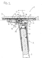
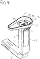
- the armrest 1 comprises a height-adjustable, in particular telescopic armrest column 2, the outer sleeve 6 of which is widened at its upper end relative to the actual column part and in this way forms a bearing head 3 for an armrest 9.
- the outer sleeve 6 of the armrest column 2 which is open at the top, but in any case has a sufficiently large opening 7, is closed by the armrest 9 in the manner of a cover.
- the armrest 9 can be rotated relative to the armrest column 2 about a vertical axis of rotation 8 and linearly displaced in the armrest longitudinal direction 21 with respect to the armrest column 2.
- the armrest 9 rests on the edge 52 of the opening 7 of the armrest column 2 during both movements.
- the opening edge 52 and the underside 40 of the armrest 9 thus at the same time limit the interior 10 of the armrest column 2 towards the top.
- an actuating button 4 is provided which protrudes through an opening in the armrest column 2 that is open to the outside.
- the armrest column 2 can be fastened to the substructure of the office chair (not shown) with the aid of an armrest support 5 extending horizontally at its lower foot end.
- the information "back / front” or “top / bottom” or “vertical / horizontal” etc. relate to the normal state of use of the office chair.
- the armrest 9 comprises a base support 11 and a support body 12 detachably connected to the base support 11.
- the base support 11 and support body 12 can, for example, form a screw, latch, snap or clamp connection be connected to each other.
- a guide slot 31 running in the longitudinal direction 21 of the armrest is provided in the base support 11 of the armrest 9. This serves to provide a link guide for linear displacement of the armrest 9 relative to the armrest support 2.
- a holding plate 13 is arranged between the base support 11 and the support body 12 as a transmission or driver or coupling element. In the assembled state, the holding plate 13 rests against both the upper side 14 of the base support 11 and the underside 15 of the support body 12 and is connected to the base support 11 and / or the support body 12 in such a way that it forms a movement unit with these two components.
- the length of the holding plate 13 (seen in the longitudinal direction of the armrest 21) is greater than the length of the guide slot 31, so that the holding plate 13 at least partially covers the guide slot 31 in all positions of these two components relative to one another.
- two openings 34 are provided for receiving locking screws 32 which, for connecting the armrest 9 to the armrest column 2, connect the holding plate 13 to two sliding blocks 36 which, with their necks 37, connect the guide slot 31 stick through.
- the necks 37 lie as guide elements in the guide slot 31.
- a rotating piece 23 of a pivot bearing 22 arranged in the armrest column 2, which is for the Rotation of the armrest 9 provides required rotation mechanism.
- the rotary bearing 22 comprises means for mounting the rotary piece 23.
- the circular cylindrical rotating piece 23 is located in a correspondingly dimensioned bearing bush 24 designed to support and guide the rotating piece 23.
- the bearing bush 24 is pot-shaped with a bottom 25 and wall 26.
- a dome-like raised slide bearing point 38 is provided in the center, which cooperates with a slide bearing point 39 also provided centrally on the rotating piece 23 there.
- the position of the rotating piece 23 in the bearing bush 24 is secured with the aid of a locking screw 33.
- the rotating piece 23 is provided in the center with an opening 35 through which the locking screw 33 can be passed and screwed into a threaded opening 41 provided in the center of the sliding bearing point 38 of the bearing bushing 24.
- the location of the axis of rotation 8 defined by the bearings 38, 39 is offset from the central longitudinal axis 18 of the armrest column 2, which in the example shown here runs obliquely to the vertical, with a view to the use of the armrest 1 for ergonomic reasons.
- the bearing bush 24 or another suitable means for mounting the rotating piece 23 can be designed as an integrated part of the armrest column 2.
- the bearing bush 24 can be injection molded onto the armrest column 2 or can be connected in one piece to the armrest column 2 in some other way.
- the bearing bush 24 or another suitable bearing means can also, as in that illustrated example, be designed as a separate component. In this case, the bearing bush 24 must be connected sufficiently firmly to the armrest column 2.
- the bearing bush 24 is provided for this purpose with a mounting plate 27, which connects to the bearing bush 24 on one side and extends the bottom 25 of the bearing bush 24 to one side.
- the mounting plate 27 has openings 28 for mounting screws 29, with which the pivot bearing 22 is connected to correspondingly designed connection points 30 of the armrest column 2.
- the bearing bush 24 rests with its underside 16 on the side opposite the mounting plate 27 on a support section 17 of the armrest column 2, which is provided by the widening of the outer sleeve 6. A particularly stable assembly of the pivot bearing 22 in the armrest column 2 is thereby achieved.
- the dome-like sliding blocks 36 are formed in one piece together with the central part 19, which forms the slide bearing point 39 and at the same time also has the opening 35.
- This central part 19 lies in a receptacle provided for this purpose in the base body 56 of the rotating piece 23.
- the sliding blocks 36 protrude vertically upward from this base body 56 into the opening 7 at the end of the outer sleeve 6.
- the edge 52 of the opening 7 defines a horizontal parting plane (in the Fig. 1 and 2 indicated by a broken line), which separates an upper armrest assembly, comprising the armrest 9, and a lower armrest assembly, comprising the armrest column 2, from one another.
- the rotating mechanism here the rotating bearing 22 with the bearing bushing 24 and rotating piece 23, is part of the lower armrest assembly, while the upper armrest assembly can be rotated relative to the lower armrest assembly by the rotating mechanism.
- the rotating mechanism is part of an assembly, which is characterized in that neither this assembly as a whole, nor parts of this assembly can perform lateral movements within a horizontal spatial plane; this assembly as a whole can neither perform a linear movement nor a rotary movement.
- both the linear movement and the rotary movement of the armrest 9 can be controlled with suitable positioning or operating means.
- the mounting plate 13 has a locking lug 42 which engages in the locking recesses 43 provided on the base support 11 and forms a locking mechanism, preferably a sliding locking mechanism with frictional engagement.
- the latching lug 42 serves as a latching device and the latching recesses 43 serve as latching grooves which define a number of latching positions arranged in the longitudinal direction 21 of the armrest 9.
- locking lug 42 is integrated in one of the longitudinal edges 20 of the retaining plate 13, which for this purpose has a receiving opening 44 suitable for receiving the spring element.
- the locking lug protrudes from the holding plate 13 transversely to the armrest longitudinal direction 21.
- the locking recesses 43 are arranged immediately adjacent to each other at the level of the guide slot 31 on the top 14 of the base support 11, namely in the form of a strip 45 lying parallel to the guide slot 31, in the example shown here as an integrated part of a strut on the base support top 14.
- the locking lug 42 can also be formed in one piece with the retaining plate 13.
- the inside 46 of the wall 26 of the bearing bush 24 is equipped with corresponding locking recesses 47 along a wall segment corresponding to the intended angle of rotation and to attach a locking element 48 to the rotating piece 23, which engages in the locking recesses 47 in the assembled state a locking mechanism, preferably a sliding locking mechanism with frictional engagement, forms, as was also described with regard to the longitudinal adjustment.
- the latching element 48 is a spring-loaded latching cylinder made of a non-resilient material, which rests in a receiving pocket 50 in the rotating piece 22 formed on the outside 49 of the rotating piece 23.
- the latching element 48 is pressed against the latching recesses 47 with the aid of a spring element 51 likewise lying in the receiving pocket 50.
- a self-resilient latching element can also be provided for the latching device of the rotary adjustment.
- the number of locking steps can be selected according to the adjustment path.
- the resistance to be overcome during the adjustment and thus the strength of the haptic feedback and, if desired, the volume of an acoustic feedback can be set.
- the maximum angle of rotation of the rotating piece 23 is determined by stops.
- a recess 53 is provided in the wall 26 of the bearing bush 25, into which a recess 53 on the base body 56 of the rotating piece 23 protruding radially outward movement limiter 54.
- the limiter 54 strikes the vertical edges 55 of the recess 53.
Landscapes
- Health & Medical Sciences (AREA)
- Dentistry (AREA)
- General Health & Medical Sciences (AREA)
- Seats For Vehicles (AREA)
- Rehabilitation Tools (AREA)
Applications Claiming Priority (1)
| Application Number | Priority Date | Filing Date | Title |
|---|---|---|---|
| DE102020101309.4A DE102020101309A1 (de) | 2020-01-21 | 2020-01-21 | Armlehne, insbesondere für einen Bürostuhl |
Publications (2)
| Publication Number | Publication Date |
|---|---|
| EP3854263A1 true EP3854263A1 (fr) | 2021-07-28 |
| EP3854263B1 EP3854263B1 (fr) | 2025-07-02 |
Family
ID=74186444
Family Applications (1)
| Application Number | Title | Priority Date | Filing Date |
|---|---|---|---|
| EP21000008.9A Active EP3854263B1 (fr) | 2020-01-21 | 2021-01-14 | Accoudoir, en particulier pour une chaise de bureau |
Country Status (4)
| Country | Link |
|---|---|
| US (1) | US11369204B2 (fr) |
| EP (1) | EP3854263B1 (fr) |
| CN (1) | CN113208339A (fr) |
| DE (1) | DE102020101309A1 (fr) |
Families Citing this family (5)
| Publication number | Priority date | Publication date | Assignee | Title |
|---|---|---|---|---|
| US11324326B2 (en) * | 2020-03-03 | 2022-05-10 | Yi-Ru Chen | Multi-directional adjustable armrest pad and chair armrest device with armrest pad |
| WO2022018645A1 (fr) * | 2020-07-22 | 2022-01-27 | Formway Furniture Limited | Ensemble bras pour une chaise |
| US11787063B2 (en) * | 2020-09-11 | 2023-10-17 | Verb Surgical Inc. | Linear lock and adjustable arm support system |
| TWI761158B (zh) * | 2021-03-30 | 2022-04-11 | 廣力達企業有限公司 | 配組式椅扶手 |
| US20240115050A1 (en) * | 2022-10-05 | 2024-04-11 | MillerKnoll, Inc. | Arm support |
Citations (1)
| Publication number | Priority date | Publication date | Assignee | Title |
|---|---|---|---|---|
| EP1405582A1 (fr) * | 2002-10-04 | 2004-04-07 | Sedus Stoll AG | Accoudoir |
Family Cites Families (16)
| Publication number | Priority date | Publication date | Assignee | Title |
|---|---|---|---|---|
| US5647638A (en) * | 1995-06-07 | 1997-07-15 | Haworth, Inc. | Height-adjustable chair arm assembly |
| IT1320404B1 (it) * | 2000-06-06 | 2003-11-26 | Pro Cord Srl | Bracciolo per sedia, poltrona o simile, e sedia utilizzante talebracciolo. |
| US6908158B2 (en) * | 2003-01-02 | 2005-06-21 | Haworth, Inc. | Lateral motion chair arm mechanism for chair arm |
| US7066546B2 (en) * | 2003-12-30 | 2006-06-27 | Hni Technologies Inc. | Horizontally adjustable chair armrest |
| US6948775B2 (en) * | 2004-02-20 | 2005-09-27 | Po-Chuan Tsai | Office chair armrest |
| US7188907B1 (en) * | 2005-05-24 | 2007-03-13 | Yu-Shan Lai | Armrest assembly having a position adjusting function |
| US7387341B1 (en) * | 2007-03-16 | 2008-06-17 | Po-Chuan Tsai | Armrest having position adjusting function |
| WO2009018402A1 (fr) * | 2007-08-01 | 2009-02-05 | Hni Technologies Inc. | Accoudoir de chaise ajustable |
| DE102007060327B4 (de) * | 2007-12-12 | 2012-04-12 | Sedus Stoll Ag | Horizontal verstellbare Armlehne und Stuhl mit einer solchen Armlehne |
| US20110254340A1 (en) * | 2010-04-20 | 2011-10-20 | Tsai Hsuan-Chin | Reversing Assembly for Office Chair Armrest |
| US8474914B2 (en) * | 2010-07-30 | 2013-07-02 | Atec International Team Co., Ltd. | Armrest adjustment device |
| DE102016002789A1 (de) * | 2016-03-07 | 2017-09-07 | Hilde Filip | Verstellbare Armstütze, insbesondere für eine Sitzvorrichtung |
| TWI607727B (zh) * | 2016-07-22 | 2017-12-11 | Pao Shen Enterprises Co Ltd | Handrail device |
| DE102017110492A1 (de) * | 2017-05-15 | 2018-11-15 | Bock 1 Gmbh & Co. Kg | Armlehne, insbesondere für einen Bürostuhl |
| IT201900014490A1 (it) * | 2019-08-09 | 2021-02-09 | Brado S P A | Dispositivo di regolazione della posizione di un bracciolo di una sedia. |
| TWI702022B (zh) * | 2019-10-29 | 2020-08-21 | 堡勝企業股份有限公司 | 旋轉定位機構、扶手座可旋轉的扶手架及椅子 |
-
2020
- 2020-01-21 DE DE102020101309.4A patent/DE102020101309A1/de active Pending
-
2021
- 2021-01-14 EP EP21000008.9A patent/EP3854263B1/fr active Active
- 2021-01-19 CN CN202110066397.4A patent/CN113208339A/zh active Pending
- 2021-01-21 US US17/154,084 patent/US11369204B2/en active Active
Patent Citations (1)
| Publication number | Priority date | Publication date | Assignee | Title |
|---|---|---|---|---|
| EP1405582A1 (fr) * | 2002-10-04 | 2004-04-07 | Sedus Stoll AG | Accoudoir |
Also Published As
| Publication number | Publication date |
|---|---|
| US20210219729A1 (en) | 2021-07-22 |
| EP3854263B1 (fr) | 2025-07-02 |
| DE102020101309A1 (de) | 2021-07-22 |
| CN113208339A (zh) | 2021-08-06 |
| US11369204B2 (en) | 2022-06-28 |
Similar Documents
| Publication | Publication Date | Title |
|---|---|---|
| EP3854263B1 (fr) | Accoudoir, en particulier pour une chaise de bureau | |
| EP3403535B1 (fr) | Accoudoir, en particulier pour une chaise de bureau | |
| EP2527576B1 (fr) | Dispositif de déplacement pour éléments de séparation maintenus de manière rotative et élément de mobilier | |
| EP1971245B1 (fr) | Mecanisme a contact permanent | |
| DE10116821B4 (de) | Verstellbare Armlehnenanordnung mit einem einzigen Verstellhebel | |
| EP0635227A1 (fr) | Chaise, notamment chaise de bureau | |
| EP1868466A1 (fr) | Accoudoir, notamment pour siège de bureau | |
| EP0079530A2 (fr) | Dispositif à bascule verrouillable pour sièges de meubles d'assise | |
| EP2265784B1 (fr) | Dispositif de réglage pour meubles | |
| EP2369965B1 (fr) | Bras central destiné à maintenir une plaque supérieure de gril double ou une plaque supérieure de cuisson et gril double ou appareil de cuisson équipé de ce bras central | |
| EP3120732B1 (fr) | Mecanisme de siege de bureau | |
| EP2092850A1 (fr) | Armature pour une armoire de coin | |
| EP2774509B1 (fr) | Dispositif d'orientation d'une façade de mobilier mobile | |
| EP2921077B1 (fr) | Siège de bureau | |
| EP1126114B1 (fr) | Charnière réglable | |
| EP3923767B1 (fr) | Tiroir | |
| EP2083656B1 (fr) | Accoudoir réglable en hauteur, notamment pour une chaise de bureau | |
| DE2949962C2 (de) | Scharnier mit Schließmechanismus | |
| DE4436199C1 (de) | Radiusbetätiger für Sicherheitsschalter | |
| DE102006037583A1 (de) | Lenksäule mit Easy-Entry und Memory-Funktion | |
| EP1223275B1 (fr) | Penture pour portes ou fenêtres | |
| EP2740872A2 (fr) | Palier d'angle prévu pour l'agencement recouvert | |
| EP0593881A1 (fr) | Support de siège pour meubles d'assise | |
| EP4646969A1 (fr) | Partie arrière pour un meuble d'assise et meuble d'assise | |
| DE202022105640U1 (de) | Mehrteiliger Armlehnenträger |
Legal Events
| Date | Code | Title | Description |
|---|---|---|---|
| PUAI | Public reference made under article 153(3) epc to a published international application that has entered the european phase |
Free format text: ORIGINAL CODE: 0009012 |
|
| STAA | Information on the status of an ep patent application or granted ep patent |
Free format text: STATUS: THE APPLICATION HAS BEEN PUBLISHED |
|
| AK | Designated contracting states |
Kind code of ref document: A1 Designated state(s): AL AT BE BG CH CY CZ DE DK EE ES FI FR GB GR HR HU IE IS IT LI LT LU LV MC MK MT NL NO PL PT RO RS SE SI SK SM TR |
|
| STAA | Information on the status of an ep patent application or granted ep patent |
Free format text: STATUS: REQUEST FOR EXAMINATION WAS MADE |
|
| 17P | Request for examination filed |
Effective date: 20220124 |
|
| RBV | Designated contracting states (corrected) |
Designated state(s): AL AT BE BG CH CY CZ DE DK EE ES FI FR GB GR HR HU IE IS IT LI LT LU LV MC MK MT NL NO PL PT RO RS SE SI SK SM TR |
|
| STAA | Information on the status of an ep patent application or granted ep patent |
Free format text: STATUS: EXAMINATION IS IN PROGRESS |
|
| 17Q | First examination report despatched |
Effective date: 20230421 |
|
| GRAP | Despatch of communication of intention to grant a patent |
Free format text: ORIGINAL CODE: EPIDOSNIGR1 |
|
| STAA | Information on the status of an ep patent application or granted ep patent |
Free format text: STATUS: GRANT OF PATENT IS INTENDED |
|
| GRAJ | Information related to disapproval of communication of intention to grant by the applicant or resumption of examination proceedings by the epo deleted |
Free format text: ORIGINAL CODE: EPIDOSDIGR1 |
|
| STAA | Information on the status of an ep patent application or granted ep patent |
Free format text: STATUS: EXAMINATION IS IN PROGRESS |
|
| INTG | Intention to grant announced |
Effective date: 20241220 |
|
| GRAP | Despatch of communication of intention to grant a patent |
Free format text: ORIGINAL CODE: EPIDOSNIGR1 |
|
| STAA | Information on the status of an ep patent application or granted ep patent |
Free format text: STATUS: GRANT OF PATENT IS INTENDED |
|
| INTC | Intention to grant announced (deleted) | ||
| INTG | Intention to grant announced |
Effective date: 20250129 |
|
| GRAS | Grant fee paid |
Free format text: ORIGINAL CODE: EPIDOSNIGR3 |
|
| GRAA | (expected) grant |
Free format text: ORIGINAL CODE: 0009210 |
|
| STAA | Information on the status of an ep patent application or granted ep patent |
Free format text: STATUS: THE PATENT HAS BEEN GRANTED |
|
| P01 | Opt-out of the competence of the unified patent court (upc) registered |
Free format text: CASE NUMBER: APP_23721/2025 Effective date: 20250519 |
|
| AK | Designated contracting states |
Kind code of ref document: B1 Designated state(s): AL AT BE BG CH CY CZ DE DK EE ES FI FR GB GR HR HU IE IS IT LI LT LU LV MC MK MT NL NO PL PT RO RS SE SI SK SM TR |
|
| REG | Reference to a national code |
Ref country code: GB Ref legal event code: FG4D Free format text: NOT ENGLISH |
|
| REG | Reference to a national code |
Ref country code: CH Ref legal event code: EP |
|
| REG | Reference to a national code |
Ref country code: DE Ref legal event code: R096 Ref document number: 502021007876 Country of ref document: DE |
|
| REG | Reference to a national code |
Ref country code: IE Ref legal event code: FG4D Free format text: LANGUAGE OF EP DOCUMENT: GERMAN |
|
| REG | Reference to a national code |
Ref country code: NL Ref legal event code: MP Effective date: 20250702 |
|
| PG25 | Lapsed in a contracting state [announced via postgrant information from national office to epo] |
Ref country code: PT Free format text: LAPSE BECAUSE OF FAILURE TO SUBMIT A TRANSLATION OF THE DESCRIPTION OR TO PAY THE FEE WITHIN THE PRESCRIBED TIME-LIMIT Effective date: 20251103 |
|
| PG25 | Lapsed in a contracting state [announced via postgrant information from national office to epo] |
Ref country code: NL Free format text: LAPSE BECAUSE OF FAILURE TO SUBMIT A TRANSLATION OF THE DESCRIPTION OR TO PAY THE FEE WITHIN THE PRESCRIBED TIME-LIMIT Effective date: 20250702 |
|
| PG25 | Lapsed in a contracting state [announced via postgrant information from national office to epo] |
Ref country code: IS Free format text: LAPSE BECAUSE OF FAILURE TO SUBMIT A TRANSLATION OF THE DESCRIPTION OR TO PAY THE FEE WITHIN THE PRESCRIBED TIME-LIMIT Effective date: 20251102 |
|
| PGFP | Annual fee paid to national office [announced via postgrant information from national office to epo] |
Ref country code: GB Payment date: 20251202 Year of fee payment: 6 |
|
| PG25 | Lapsed in a contracting state [announced via postgrant information from national office to epo] |
Ref country code: NO Free format text: LAPSE BECAUSE OF FAILURE TO SUBMIT A TRANSLATION OF THE DESCRIPTION OR TO PAY THE FEE WITHIN THE PRESCRIBED TIME-LIMIT Effective date: 20251002 |
|
| REG | Reference to a national code |
Ref country code: LT Ref legal event code: MG9D |
|
| PG25 | Lapsed in a contracting state [announced via postgrant information from national office to epo] |
Ref country code: FI Free format text: LAPSE BECAUSE OF FAILURE TO SUBMIT A TRANSLATION OF THE DESCRIPTION OR TO PAY THE FEE WITHIN THE PRESCRIBED TIME-LIMIT Effective date: 20250702 |
|
| PG25 | Lapsed in a contracting state [announced via postgrant information from national office to epo] |
Ref country code: HR Free format text: LAPSE BECAUSE OF FAILURE TO SUBMIT A TRANSLATION OF THE DESCRIPTION OR TO PAY THE FEE WITHIN THE PRESCRIBED TIME-LIMIT Effective date: 20250702 |
|
| PG25 | Lapsed in a contracting state [announced via postgrant information from national office to epo] |
Ref country code: GR Free format text: LAPSE BECAUSE OF FAILURE TO SUBMIT A TRANSLATION OF THE DESCRIPTION OR TO PAY THE FEE WITHIN THE PRESCRIBED TIME-LIMIT Effective date: 20251003 |
|
| PG25 | Lapsed in a contracting state [announced via postgrant information from national office to epo] |
Ref country code: SE Free format text: LAPSE BECAUSE OF FAILURE TO SUBMIT A TRANSLATION OF THE DESCRIPTION OR TO PAY THE FEE WITHIN THE PRESCRIBED TIME-LIMIT Effective date: 20250702 Ref country code: CZ Free format text: LAPSE BECAUSE OF FAILURE TO SUBMIT A TRANSLATION OF THE DESCRIPTION OR TO PAY THE FEE WITHIN THE PRESCRIBED TIME-LIMIT Effective date: 20250702 |
|
| PG25 | Lapsed in a contracting state [announced via postgrant information from national office to epo] |
Ref country code: LV Free format text: LAPSE BECAUSE OF FAILURE TO SUBMIT A TRANSLATION OF THE DESCRIPTION OR TO PAY THE FEE WITHIN THE PRESCRIBED TIME-LIMIT Effective date: 20250702 |
|
| PG25 | Lapsed in a contracting state [announced via postgrant information from national office to epo] |
Ref country code: PL Free format text: LAPSE BECAUSE OF FAILURE TO SUBMIT A TRANSLATION OF THE DESCRIPTION OR TO PAY THE FEE WITHIN THE PRESCRIBED TIME-LIMIT Effective date: 20250702 Ref country code: BG Free format text: LAPSE BECAUSE OF FAILURE TO SUBMIT A TRANSLATION OF THE DESCRIPTION OR TO PAY THE FEE WITHIN THE PRESCRIBED TIME-LIMIT Effective date: 20250702 |
|
| PG25 | Lapsed in a contracting state [announced via postgrant information from national office to epo] |
Ref country code: RS Free format text: LAPSE BECAUSE OF FAILURE TO SUBMIT A TRANSLATION OF THE DESCRIPTION OR TO PAY THE FEE WITHIN THE PRESCRIBED TIME-LIMIT Effective date: 20251002 |
|
| PG25 | Lapsed in a contracting state [announced via postgrant information from national office to epo] |
Ref country code: ES Free format text: LAPSE BECAUSE OF FAILURE TO SUBMIT A TRANSLATION OF THE DESCRIPTION OR TO PAY THE FEE WITHIN THE PRESCRIBED TIME-LIMIT Effective date: 20250702 |
|
| PG25 | Lapsed in a contracting state [announced via postgrant information from national office to epo] |
Ref country code: SM Free format text: LAPSE BECAUSE OF FAILURE TO SUBMIT A TRANSLATION OF THE DESCRIPTION OR TO PAY THE FEE WITHIN THE PRESCRIBED TIME-LIMIT Effective date: 20250702 |
|
| REG | Reference to a national code |
Ref country code: DE Ref legal event code: R097 Ref document number: 502021007876 Country of ref document: DE |
|
| PG25 | Lapsed in a contracting state [announced via postgrant information from national office to epo] |
Ref country code: DK Free format text: LAPSE BECAUSE OF FAILURE TO SUBMIT A TRANSLATION OF THE DESCRIPTION OR TO PAY THE FEE WITHIN THE PRESCRIBED TIME-LIMIT Effective date: 20250702 |
|
| PGFP | Annual fee paid to national office [announced via postgrant information from national office to epo] |
Ref country code: DE Payment date: 20260112 Year of fee payment: 6 |
|
| PGFP | Annual fee paid to national office [announced via postgrant information from national office to epo] |
Ref country code: IT Payment date: 20260120 Year of fee payment: 6 |
|
| PG25 | Lapsed in a contracting state [announced via postgrant information from national office to epo] |
Ref country code: SK Free format text: LAPSE BECAUSE OF FAILURE TO SUBMIT A TRANSLATION OF THE DESCRIPTION OR TO PAY THE FEE WITHIN THE PRESCRIBED TIME-LIMIT Effective date: 20250702 Ref country code: EE Free format text: LAPSE BECAUSE OF FAILURE TO SUBMIT A TRANSLATION OF THE DESCRIPTION OR TO PAY THE FEE WITHIN THE PRESCRIBED TIME-LIMIT Effective date: 20250702 |
|
| PLBE | No opposition filed within time limit |
Free format text: ORIGINAL CODE: 0009261 |
|
| STAA | Information on the status of an ep patent application or granted ep patent |
Free format text: STATUS: NO OPPOSITION FILED WITHIN TIME LIMIT |
|
| REG | Reference to a national code |
Ref country code: CH Ref legal event code: L10 Free format text: ST27 STATUS EVENT CODE: U-0-0-L10-L00 (AS PROVIDED BY THE NATIONAL OFFICE) Effective date: 20260518 |
|
| 26N | No opposition filed |
Effective date: 20260407 |
|
| PG25 | Lapsed in a contracting state [announced via postgrant information from national office to epo] |
Ref country code: LT Free format text: LAPSE BECAUSE OF FAILURE TO SUBMIT A TRANSLATION OF THE DESCRIPTION OR TO PAY THE FEE WITHIN THE PRESCRIBED TIME-LIMIT Effective date: 20250702 |