EP3854548A1 - Appareil de coupe de tige d'électrode destiné à un élément de batterie - Google Patents
Appareil de coupe de tige d'électrode destiné à un élément de batterie Download PDFInfo
- Publication number
- EP3854548A1 EP3854548A1 EP19887330.9A EP19887330A EP3854548A1 EP 3854548 A1 EP3854548 A1 EP 3854548A1 EP 19887330 A EP19887330 A EP 19887330A EP 3854548 A1 EP3854548 A1 EP 3854548A1
- Authority
- EP
- European Patent Office
- Prior art keywords
- electrode lead
- cutting
- cut
- battery cell
- point
- Prior art date
- Legal status (The legal status is an assumption and is not a legal conclusion. Google has not performed a legal analysis and makes no representation as to the accuracy of the status listed.)
- Granted
Links
Images


Classifications
-
- B—PERFORMING OPERATIONS; TRANSPORTING
- B23—MACHINE TOOLS; METAL-WORKING NOT OTHERWISE PROVIDED FOR
- B23K—SOLDERING OR UNSOLDERING; WELDING; CLADDING OR PLATING BY SOLDERING OR WELDING; CUTTING BY APPLYING HEAT LOCALLY, e.g. FLAME CUTTING; WORKING BY LASER BEAM
- B23K26/00—Working by laser beam, e.g. welding, cutting or boring
- B23K26/36—Removing material
- B23K26/38—Removing material by boring or cutting
-
- H—ELECTRICITY
- H01—ELECTRIC ELEMENTS
- H01M—PROCESSES OR MEANS, e.g. BATTERIES, FOR THE DIRECT CONVERSION OF CHEMICAL ENERGY INTO ELECTRICAL ENERGY
- H01M10/00—Secondary cells; Manufacture thereof
- H01M10/04—Construction or manufacture in general
- H01M10/0404—Machines for assembling batteries
-
- B—PERFORMING OPERATIONS; TRANSPORTING
- B26—HAND CUTTING TOOLS; CUTTING; SEVERING
- B26D—CUTTING; DETAILS COMMON TO MACHINES FOR PERFORATING, PUNCHING, CUTTING-OUT, STAMPING-OUT OR SEVERING
- B26D1/00—Cutting through work characterised by the nature or movement of the cutting member or particular materials not otherwise provided for; Apparatus or machines therefor; Cutting members therefor
- B26D1/01—Cutting through work characterised by the nature or movement of the cutting member or particular materials not otherwise provided for; Apparatus or machines therefor; Cutting members therefor involving a cutting member which does not travel with the work
- B26D1/04—Cutting through work characterised by the nature or movement of the cutting member or particular materials not otherwise provided for; Apparatus or machines therefor; Cutting members therefor involving a cutting member which does not travel with the work having a linearly-movable cutting member
- B26D1/06—Cutting through work characterised by the nature or movement of the cutting member or particular materials not otherwise provided for; Apparatus or machines therefor; Cutting members therefor involving a cutting member which does not travel with the work having a linearly-movable cutting member wherein the cutting member reciprocates
- B26D1/08—Cutting through work characterised by the nature or movement of the cutting member or particular materials not otherwise provided for; Apparatus or machines therefor; Cutting members therefor involving a cutting member which does not travel with the work having a linearly-movable cutting member wherein the cutting member reciprocates of the guillotine type
- B26D1/09—Cutting through work characterised by the nature or movement of the cutting member or particular materials not otherwise provided for; Apparatus or machines therefor; Cutting members therefor involving a cutting member which does not travel with the work having a linearly-movable cutting member wherein the cutting member reciprocates of the guillotine type with a plurality of cutting members
- B26D1/095—Cutting through work characterised by the nature or movement of the cutting member or particular materials not otherwise provided for; Apparatus or machines therefor; Cutting members therefor involving a cutting member which does not travel with the work having a linearly-movable cutting member wherein the cutting member reciprocates of the guillotine type with a plurality of cutting members for thin material, e.g. for sheets, strips or the like
-
- B—PERFORMING OPERATIONS; TRANSPORTING
- B23—MACHINE TOOLS; METAL-WORKING NOT OTHERWISE PROVIDED FOR
- B23K—SOLDERING OR UNSOLDERING; WELDING; CLADDING OR PLATING BY SOLDERING OR WELDING; CUTTING BY APPLYING HEAT LOCALLY, e.g. FLAME CUTTING; WORKING BY LASER BEAM
- B23K26/00—Working by laser beam, e.g. welding, cutting or boring
-
- B—PERFORMING OPERATIONS; TRANSPORTING
- B26—HAND CUTTING TOOLS; CUTTING; SEVERING
- B26D—CUTTING; DETAILS COMMON TO MACHINES FOR PERFORATING, PUNCHING, CUTTING-OUT, STAMPING-OUT OR SEVERING
- B26D1/00—Cutting through work characterised by the nature or movement of the cutting member or particular materials not otherwise provided for; Apparatus or machines therefor; Cutting members therefor
- B26D1/01—Cutting through work characterised by the nature or movement of the cutting member or particular materials not otherwise provided for; Apparatus or machines therefor; Cutting members therefor involving a cutting member which does not travel with the work
- B26D1/04—Cutting through work characterised by the nature or movement of the cutting member or particular materials not otherwise provided for; Apparatus or machines therefor; Cutting members therefor involving a cutting member which does not travel with the work having a linearly-movable cutting member
- B26D1/06—Cutting through work characterised by the nature or movement of the cutting member or particular materials not otherwise provided for; Apparatus or machines therefor; Cutting members therefor involving a cutting member which does not travel with the work having a linearly-movable cutting member wherein the cutting member reciprocates
-
- B—PERFORMING OPERATIONS; TRANSPORTING
- B26—HAND CUTTING TOOLS; CUTTING; SEVERING
- B26D—CUTTING; DETAILS COMMON TO MACHINES FOR PERFORATING, PUNCHING, CUTTING-OUT, STAMPING-OUT OR SEVERING
- B26D7/00—Details of apparatus for cutting, cutting-out, stamping-out, punching, perforating, or severing by means other than cutting
-
- B—PERFORMING OPERATIONS; TRANSPORTING
- B26—HAND CUTTING TOOLS; CUTTING; SEVERING
- B26D—CUTTING; DETAILS COMMON TO MACHINES FOR PERFORATING, PUNCHING, CUTTING-OUT, STAMPING-OUT OR SEVERING
- B26D7/00—Details of apparatus for cutting, cutting-out, stamping-out, punching, perforating, or severing by means other than cutting
- B26D7/0006—Means for guiding the cutter
-
- B—PERFORMING OPERATIONS; TRANSPORTING
- B26—HAND CUTTING TOOLS; CUTTING; SEVERING
- B26D—CUTTING; DETAILS COMMON TO MACHINES FOR PERFORATING, PUNCHING, CUTTING-OUT, STAMPING-OUT OR SEVERING
- B26D7/00—Details of apparatus for cutting, cutting-out, stamping-out, punching, perforating, or severing by means other than cutting
- B26D7/01—Means for holding or positioning work
-
- B—PERFORMING OPERATIONS; TRANSPORTING
- B26—HAND CUTTING TOOLS; CUTTING; SEVERING
- B26D—CUTTING; DETAILS COMMON TO MACHINES FOR PERFORATING, PUNCHING, CUTTING-OUT, STAMPING-OUT OR SEVERING
- B26D7/00—Details of apparatus for cutting, cutting-out, stamping-out, punching, perforating, or severing by means other than cutting
- B26D7/01—Means for holding or positioning work
- B26D7/018—Holding the work by suction
-
- H—ELECTRICITY
- H01—ELECTRIC ELEMENTS
- H01M—PROCESSES OR MEANS, e.g. BATTERIES, FOR THE DIRECT CONVERSION OF CHEMICAL ENERGY INTO ELECTRICAL ENERGY
- H01M10/00—Secondary cells; Manufacture thereof
- H01M10/05—Accumulators with non-aqueous electrolyte
- H01M10/052—Li-accumulators
-
- H—ELECTRICITY
- H01—ELECTRIC ELEMENTS
- H01M—PROCESSES OR MEANS, e.g. BATTERIES, FOR THE DIRECT CONVERSION OF CHEMICAL ENERGY INTO ELECTRICAL ENERGY
- H01M50/00—Constructional details or processes of manufacture of the non-active parts of electrochemical cells other than fuel cells, e.g. hybrid cells
- H01M50/10—Primary casings; Jackets or wrappings
- H01M50/102—Primary casings; Jackets or wrappings characterised by their shape or physical structure
- H01M50/105—Pouches or flexible bags
-
- H—ELECTRICITY
- H01—ELECTRIC ELEMENTS
- H01M—PROCESSES OR MEANS, e.g. BATTERIES, FOR THE DIRECT CONVERSION OF CHEMICAL ENERGY INTO ELECTRICAL ENERGY
- H01M50/00—Constructional details or processes of manufacture of the non-active parts of electrochemical cells other than fuel cells, e.g. hybrid cells
- H01M50/20—Mountings; Secondary casings or frames; Racks, modules or packs; Suspension devices; Shock absorbers; Transport or carrying devices; Holders
-
- H—ELECTRICITY
- H01—ELECTRIC ELEMENTS
- H01M—PROCESSES OR MEANS, e.g. BATTERIES, FOR THE DIRECT CONVERSION OF CHEMICAL ENERGY INTO ELECTRICAL ENERGY
- H01M50/00—Constructional details or processes of manufacture of the non-active parts of electrochemical cells other than fuel cells, e.g. hybrid cells
- H01M50/50—Current conducting connections for cells or batteries
- H01M50/531—Electrode connections inside a battery casing
-
- H—ELECTRICITY
- H01—ELECTRIC ELEMENTS
- H01M—PROCESSES OR MEANS, e.g. BATTERIES, FOR THE DIRECT CONVERSION OF CHEMICAL ENERGY INTO ELECTRICAL ENERGY
- H01M2220/00—Batteries for particular applications
- H01M2220/30—Batteries in portable systems, e.g. mobile phone, laptop
-
- H—ELECTRICITY
- H01—ELECTRIC ELEMENTS
- H01M—PROCESSES OR MEANS, e.g. BATTERIES, FOR THE DIRECT CONVERSION OF CHEMICAL ENERGY INTO ELECTRICAL ENERGY
- H01M50/00—Constructional details or processes of manufacture of the non-active parts of electrochemical cells other than fuel cells, e.g. hybrid cells
- H01M50/20—Mountings; Secondary casings or frames; Racks, modules or packs; Suspension devices; Shock absorbers; Transport or carrying devices; Holders
- H01M50/204—Racks, modules or packs for multiple batteries or multiple cells
- H01M50/207—Racks, modules or packs for multiple batteries or multiple cells characterised by their shape
- H01M50/211—Racks, modules or packs for multiple batteries or multiple cells characterised by their shape adapted for pouch cells
-
- Y—GENERAL TAGGING OF NEW TECHNOLOGICAL DEVELOPMENTS; GENERAL TAGGING OF CROSS-SECTIONAL TECHNOLOGIES SPANNING OVER SEVERAL SECTIONS OF THE IPC; TECHNICAL SUBJECTS COVERED BY FORMER USPC CROSS-REFERENCE ART COLLECTIONS [XRACs] AND DIGESTS
- Y02—TECHNOLOGIES OR APPLICATIONS FOR MITIGATION OR ADAPTATION AGAINST CLIMATE CHANGE
- Y02E—REDUCTION OF GREENHOUSE GAS [GHG] EMISSIONS, RELATED TO ENERGY GENERATION, TRANSMISSION OR DISTRIBUTION
- Y02E60/00—Enabling technologies; Technologies with a potential or indirect contribution to GHG emissions mitigation
- Y02E60/10—Energy storage using batteries
Definitions
- the present invention relates to an electrode lead cutting apparatus capable of cutting an electrode lead of a battery cell to the setting length of the electrode lead.
- EV electric vehicle
- HEV hybrid electric vehicle
- Plug-In HEV plug-in hybrid electric vehicle
- Such secondary batteries is a lithium secondary battery having a high energy density and a high voltage, into which much research has been carried out and which has also been commercialized and widely used.
- the demand for a pouch-type battery cell which has a small thickness, is easily arranged in a stacked state, and is partially deformable, is high in terms of the shape of the battery.
- the pouch-type battery cell is configured to have a structure in which an electrode assembly and an electrolytic solution are received in a pouch-type laminate sheet capable of receiving the electrode assembly therein.
- the laminate sheet is called a "pouch-type battery case," and a resin layer of the laminate sheet is characterized in that the resin layer is fusible by heat.
- the pouch-type battery cell is particularly configured to have a structure in which the laminate sheet wraps the electrode assembly such that the electrode assembly is not exposed outside, and is configured to have a structure in which heat and pressure are applied to portions of the laminate sheet to be sealed overlapping at the outer edge of the battery case in order to seal the sheet.
- the battery cell is configured to have a structure in which the outer edges of the battery case are sealed in the state in which electrode leads protrude outwards from the battery case.
- each of the electrode leads is made of a conductive metal material, is formed in a bar shape, and has a polygonal structure having angled corners when viewed in a plan view.
- the electrode lead is configured to have a long rectangular structure.
- the electrode leads are cut to predetermined lengths, e.g. lengths that the electrode leads can easily be connected to a printed circuit board (PCB) (not shown) or an external electric device (not shown), in the state of being inserted into cutting jigs configured to intersect up and down.
- PCB printed circuit board
- an external electric device not shown
- the cutting position of the electrode lead may be tilted due to the property of the electrode lead, such as flexibility.
- An embodiment of the present invention provides an electrode lead cutting apparatus capable of accurately cutting a point of an electrode lead to be cut.
- An electrode lead cutting apparatus for battery cells may include a cell fixing unit configured to fix a battery cell, an electrode lead fixing unit configured to supply air to an electrode lead of the battery cell in order to fix a point of the electrode lead to be cut, and an electrode lead cutting unit configured to cut the point of the electrode lead to be cut.
- the cell fixing unit may include a suction plate configured to suction the battery cell in a vacuum state.
- the electrode lead cutting unit may include a cutting blade configured to cut the electrode lead in the state of being in contact with the point of the electrode lead to be cut, and the cutting blade may include a first cutting blade located above the point of the electrode lead to be cut and a second cutting blade located below the point of the electrode lead to be cut.
- the electrode lead cutting unit may further include a guide block, and at least one of the first cutting blade and the second cutting blade may be coupled to the guide block so as to be movable upwards and downwards.
- the electrode lead cutting unit may include a laser oscillator configured to apply a laser beam to the point of the electrode lead to be cut.
- the electrode lead cutting apparatus may further include an electrode lead supporting unit disposed under the electrode lead, the electrode lead supporting unit being configured to support the electrode lead.
- the electrode lead supporting unit may include a magnetic block configured to fix the electrode lead using magnetic force.
- an electrode lead cutting method for battery cells may include a step of loading a battery cell having an electrode lead exposed therefrom, a step of supplying air from above the electrode lead to fix a point of the electrode lead to be cut, and a step of cutting the fixed point of the electrode lead to be cut.
- the electrode lead cutting method may further include a step of providing magnetic force from under the electrode lead to fix the electrode lead using the magnetic force at the time of cutting the electrode lead.
- a part in the case in which a part "includes" a component, this means that the part may not exclude another component but may further include another component unless otherwise mentioned.
- the terms used herein are intended only to mention specific embodiments, not to limit the present invention, and may be interpreted as concepts that are understood by a person having ordinary skill in the art to which the present invention pertains unless otherwise defined in this specification.
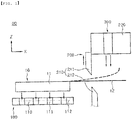
- FIG. 1 is a view schematically showing an electrode lead cutting apparatus according to a first embodiment of the present invention.
- the electrode lead cutting apparatus 50 includes a cell fixing unit 100, an electrode lead cutting unit 200, and an electrode lead fixing unit 300.
- the longitudinal direction of an electrode lead in which the electrode lead extends is set to an X-axis direction
- the width direction of the electrode lead perpendicular to the X-axis direction is set to a Y-axis direction
- the direction perpendicular to the X-axis and Y-axis directions is set to a Z-axis direction.
- a battery cell 10 that is applied to the embodiment of the present invention may be configured to have a structure in which an electrode assembly and an electrolytic solution are received in a pouch sheathing member 11.
- the battery cell 10 may be a pouch-type battery cell.
- the battery cell may be a secondary battery that performs charging and discharging operations.
- An electrode lead 12 may be provided outside the pouch sheathing member 11 in a protruding form. One end of the electrode lead 12 is electrically connected to the electrode assembly, and the other end of the electrode lead 12 is exposed outside the pouch sheathing member 11, whereby the electrode lead 12 may serve as a connection terminal of the battery cell 10.
- the cell fixing unit 100 fixes the battery cell 10, which is a processing target.
- the cell fixing unit 100 may include a suction plate 110 configured to suction the battery cell 10 in a vacuum state.
- the suction plate 110 may be formed in a flat shape such that one surface of the battery cell 10 is seated on the suction plate.
- the battery cell 10 may be disposed on the suction plate 110 in the horizontal direction.
- the battery cell 10 may be seated on the suction plate 110 in the form in which the electrode lead 12 exposed outside the electrode assembly extends in the X-axis direction.
- At least one vacuum hole 111 may be formed in the suction plate 110.
- the vacuum hole 111 may be formed through the suction plate 110 in the Z-axis direction.
- the suction plate 110 may suction a battery cell located so as to correspond to the vacuum hole 111. Consequently, the battery cell may be suctioned on the suction plate 110 in a vacuum state, whereby the battery cell may be stably fixed during cutting of the electrode lead 12.
- a seating recess 112 may be formed in one surface of the suction plate 110 on which the battery cell 10 is seated, e.g. the upper surface of the suction plate 110.
- the seating recess 112 is formed so as to be recessed from the upper surface of the suction plate 110 in a concave shape in the downward direction.
- the seating recess 112 is formed so as to correspond to the external appearance of the battery cell 10. Consequently, the battery cell 10 may be seated in the seating recess 112, whereby movement of the battery cell in the X-axis or Y-axis direction may be prevented. Therefore, it is possible to improve the accuracy at the time of cutting the electrode lead 12.
- a gripper and the like may be applied in addition to the suction plate 110.
- the suction plate 110 is applied as the cell fixing unit 100.
- the electrode lead cutting unit 200 cuts the electrode lead 12.
- the electrode lead cutting unit 200 may include a cutting blade 210 configured to cut the electrode lead 12 in the state of being in contact with the electrode lead.
- the cutting blade 210 cuts a point of the electrode lead 12 to be cut.
- the cutting blade 210 may include a first cutting blade 211 and a second cutting blade 212.
- the first cutting blade 211 may be located above the point of the electrode lead 12 to be cut, and the second cutting blade 212 may be located below the point of the electrode lead 12 to be cut.
- the first cutting blade 211 and the second cutting blade 212 may be disposed so as to cut the electrode lead 12 while intersecting each other.
- the electrode lead cutting unit 200 may include a guide block 220.
- the guide block 220 may guide movement of the cutting blade 210 in the Z-axis direction, i.e. the upward-downward movement of the cutting blade, while supporting the cutting blade 210.
- the first cutting blade 211 and the second cutting blade 212 may be coupled to the guide block 220, and at least one of the first cutting blade 211 and the second cutting blade 212 may be coupled to the guide block 220 so as to be movable upwards and downwards.
- the guide block 220 may be provided with a guide rail (not shown) configured to guide the upward-downward movement of the cutting blade 210.
- the electrode lead fixing unit 300 fixes the electrode lead 12 at the time of cutting the electrode lead 12.
- An air blower configured to supply air to the electrode lead 12 of the battery cell 10 in order to fix the point of the electrode lead 12 to be cut may be applied as the electrode lead fixing unit 300.
- the air blower may be mounted to the guide block 220 so as to be located above the electrode lead 12.
- the air blower may be disposed at a position corresponding to the end of the electrode lead 12. That is, the cutting blade 210 may be disposed at one side of the battery cell 10, and the air blower may be disposed at one side of the cutting blade 210.
- the longitudinal direction of the electrode lead 12 does not become perpendicular to the axial direction of the cutting blade 210. In the case in which electrode lead 12 is cut in this state, there may occur an error between the cutting length and the setting length of the electrode lead 12.
- FIG. 2 is a view showing a method of cutting an electrode of a battery cell according to a first embodiment of the present invention.
- the electrode lead cutting method includes a cell seating step (S10), a cell fixing step (S20), an electrode lead fixing step (S30), and an electrode lead cutting step (S40).
- a battery cell 10 is loaded on the suction plate 110.
- the battery cell 10 may be loaded on the suction plate 110 by a transfer unit, such as a robot arm.
- An electrode lead 12, which is a target to be cut, may be exposed outside the suction plate 110.
- a metal that exhibits high conductivity while not causing a chemical change in the battery may be applied as the electrode lead 12 of the battery cell 10, although not particularly restricted.
- the electrode lead 12 may be selected from the group consisting of copper (Cu), aluminum (Al), nickel (Ni), iron (Fe), carbon (C), chromium (Cr), manganese (Mn), and an alloy including two or more thereof, and may be formed in the shape of a thin plate having a thickness of 0.1 mm to 1.0 mm.
- the battery cell 10 is fixed. Since the seating recess 112 is formed in the suction plate 110 so as to correspond to the external appearance of the battery cell 10, movement of the battery cell 10 loaded on the suction plate 110 in the X-axis or Y-axis direction may be prevented. In addition, the battery cell 10 is suctioned by the suction plate 110, in which the vacuum hole 111 is formed, in a vacuum state, whereby the battery cell may be stably fixed in the cutting process.
- the electrode lead 12 may exhibit predetermined flexibility since the electrode lead has a thickness of about 0.1 mm to 1.0 mm.
- the cutting operation may be performed on the electrode lead 12 in the state in which the end of the electrode lead is tilted.
- the electrode lead 12 may be in the state of being tilted upwards.
- the electrode lead 12 is cut in this state, there may occur the difference between the cutting length and the setting length of the electrode lead.
- air is injected from the air blower disposed above the electrode lead 12. In the case in which the air is supplied, the electrode lead 12 is pushed downwards, and the pushed electrode lead 12 is maintained in the horizontal state. Consequently, the point of the electrode lead 12 to be cut may be stably secured.
- the electrode lead 12 is cut to the setting length thereof. That is, at least one of the first cutting blade 211 and the second cutting blade 212 is moved upwards and downwards to cut the electrode lead 12 in the state in which the electrode lead 12 is maintained in the horizontal state by the air blower. Since the cutting operation is performed in the state in which the electrode lead 12 is maintained in the horizontal state and the point of the electrode lead 12 to be cut is fixed, as described above, it is possible to minimize an error between the cutting length and the setting length of the electrode lead 12 at the time of cutting the electrode lead.
- FIG. 3 is a view schematically showing an electrode cutting apparatus according to a second embodiment of the present invention.
- the electrode lead cutting apparatus 50 includes a cell fixing unit 100, an electrode lead cutting unit 200, an electrode lead fixing unit 300, and an electrode lead supporting unit 400.
- Constructions of the cell fixing unit 100, the electrode lead cutting unit 200, and the electrode lead fixing unit 300 are identical or similar to those in the first embodiment, and therefore a detailed description thereof will be omitted.
- the electrode lead supporting unit 400 is disposed under an electrode lead 12 to support the electrode lead 12.
- the electrode lead supporting unit 400 may prevent drooping of the electrode lead 12 at the time of cutting the electrode lead 12. For example, when air is supplied downwards from an air blower located about the electrode lead 12, the electrode lead 12 may be drooped by the pressure at which the air is supplied.
- the electrode lead supporting unit 400 supports the electrode lead 12 under the electrode lead 12, whereby it is possible to prevent drooping of the electrode lead 12. Consequently, it is possible to secure a correct point of the electrode lead 12 to be cut at the time of cutting the electrode lead.
- the electrode lead supporting unit 400 may include a magnetic block.
- the magnetic block may fix the electrode lead 12 using magnetic force. Consequently, the electrode lead 12 may be more securely fixed by the air blower, which supplies air from above the electrode lead 12, and the magnetic block, which fixes the lower side of the electrode lead 12 using magnetic force. Since the fixed state of the electrode lead 12 is secured, it is possible to easily secure the point of the electrode lead 12 to be cut. Consequently, it is possible to minimize an error between the cutting length and the setting length of the electrode lead 12 at the time of cutting the electrode lead.
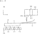
- FIG. 4 is a view schematically showing an electrode lead cutting apparatus according to a third embodiment of the present invention.
- the electrode lead cutting apparatus 50 includes a cell fixing unit 100, an electrode lead cutting unit, and an electrode lead fixing unit 300.
- Constructions of the cell fixing unit 100 and the electrode lead fixing unit 300 are identical or similar to those in the first embodiment, and therefore a detailed description thereof will be omitted.
- burrs or electrode particles may be generated on the end surface of the electrode lead 12.
- the burrs or the electrode particles generated on the end surface of the electrode lead 12 may be mixed in a battery cell 10, whereby performance of the battery cell 10 may be deteriorated.
- the electrode lead cutting unit of the third embodiment may include a laser oscillator 230.
- the laser oscillator 230 may apply a laser beam to a point of the electrode lead 12 to be cut in order to cut the electrode lead 12. Consequently, it is possible to minimize the amount of burrs or electrode particles generated on the cut surface of the electrode lead 12 at the time of cutting the electrode lead 12.
- air is supplied to a point of an electrode lead to be cut through an air blower at the time of cutting the electrode lead such that the electrode lead is maintained in a horizontal state, whereby it is possible to minimize an error in the cutting length of the electrode lead at the time of cutting the electrode lead.
- a supporting unit such as a magnetic block, is disposed under the electrode lead at the time of cutting the electrode lead, whereby it is possible to prevent the point of the electrode lead to be cut from being tilted in the downward direction at the time of supplying air through the air blower.
Landscapes
- Engineering & Computer Science (AREA)
- Mechanical Engineering (AREA)
- Life Sciences & Earth Sciences (AREA)
- Forests & Forestry (AREA)
- Electrochemistry (AREA)
- Chemical Kinetics & Catalysis (AREA)
- Chemical & Material Sciences (AREA)
- General Chemical & Material Sciences (AREA)
- Physics & Mathematics (AREA)
- Optics & Photonics (AREA)
- Plasma & Fusion (AREA)
- Manufacturing & Machinery (AREA)
- Battery Electrode And Active Subsutance (AREA)
- Connection Of Batteries Or Terminals (AREA)
Applications Claiming Priority (2)
| Application Number | Priority Date | Filing Date | Title |
|---|---|---|---|
| KR1020180145971A KR102655101B1 (ko) | 2018-11-23 | 2018-11-23 | 배터리 셀의 전극리드 절단장치 |
| PCT/KR2019/015389 WO2020105939A1 (fr) | 2018-11-23 | 2019-11-13 | Appareil de coupe de tige d'électrode destiné à un élément de batterie |
Publications (3)
| Publication Number | Publication Date |
|---|---|
| EP3854548A1 true EP3854548A1 (fr) | 2021-07-28 |
| EP3854548A4 EP3854548A4 (fr) | 2022-01-12 |
| EP3854548B1 EP3854548B1 (fr) | 2025-03-12 |
Family
ID=70774733
Family Applications (1)
| Application Number | Title | Priority Date | Filing Date |
|---|---|---|---|
| EP19887330.9A Active EP3854548B1 (fr) | 2018-11-23 | 2019-11-13 | Appareil de coupe de tige d'électrode destiné à un élément de batterie |
Country Status (8)
| Country | Link |
|---|---|
| US (1) | US11491582B2 (fr) |
| EP (1) | EP3854548B1 (fr) |
| JP (1) | JP7045573B2 (fr) |
| KR (1) | KR102655101B1 (fr) |
| CN (1) | CN111741837A (fr) |
| ES (1) | ES3021482T3 (fr) |
| HU (1) | HUE071025T2 (fr) |
| WO (1) | WO2020105939A1 (fr) |
Families Citing this family (7)
| Publication number | Priority date | Publication date | Assignee | Title |
|---|---|---|---|---|
| KR102869905B1 (ko) * | 2020-11-13 | 2025-10-14 | 주식회사 엘지에너지솔루션 | 전극 커팅장치 |
| KR102279118B1 (ko) * | 2021-04-13 | 2021-07-19 | (주)지피아이 | 스크랩 및 흄 흡입장치를 구비한 레이저 노칭장치 |
| KR102818419B1 (ko) * | 2021-10-14 | 2025-06-13 | 주식회사 엔에스머티리얼즈 | 이차전지용 리드탭 제조 방법 |
| KR102791008B1 (ko) * | 2021-12-07 | 2025-04-07 | (주)에이티비 | 폐배터리 해체 시스템 |
| KR20230125675A (ko) * | 2022-02-21 | 2023-08-29 | 주식회사 엘지에너지솔루션 | 전극 커팅 장치 및 방법 |
| KR102727850B1 (ko) * | 2024-03-25 | 2024-11-11 | 주식회사 우원기술 | 셀 스택 풀링장치 |
| KR20260011896A (ko) | 2024-07-17 | 2026-01-26 | 주식회사 엘지에너지솔루션 | 전극 조립체 제조 장치 및 방법 |
Family Cites Families (31)
| Publication number | Priority date | Publication date | Assignee | Title |
|---|---|---|---|---|
| JPH0445242Y2 (fr) * | 1987-05-11 | 1992-10-23 | ||
| JPH0747290Y2 (ja) | 1992-06-05 | 1995-11-01 | 高野ベアリング株式会社 | 連続した個装袋の分離装置 |
| JP3089351B2 (ja) | 1996-05-28 | 2000-09-18 | 古河電池株式会社 | 電池用極板へのタブ溶接装置、およびそれを用いた電池用極板の製造方法 |
| JP3787437B2 (ja) * | 1998-07-31 | 2006-06-21 | 日本特殊陶業株式会社 | 扁平型電池及びその製造方法 |
| GB2356291B (en) * | 1999-11-13 | 2003-10-22 | Rolls Royce Plc | A workpiece clamping system |
| KR100803001B1 (ko) | 2002-09-25 | 2008-02-14 | 주식회사 에스에프에이 | 전지 제조 장치 및, 방법 |
| JP2004186635A (ja) * | 2002-12-06 | 2004-07-02 | Sharp Corp | 半導体基板の切断装置および切断方法 |
| CN1979924B (zh) | 2005-12-10 | 2010-08-25 | 深圳市比克电池有限公司 | 锂离子电池极片裁切方法 |
| KR100865166B1 (ko) * | 2007-08-13 | 2008-10-24 | 회광하이테크 주식회사 | 리튬폴리머 전지용 리드필름 접합장치 |
| KR101255628B1 (ko) * | 2009-02-17 | 2013-04-16 | 주식회사 엘지화학 | 팩 제조설계가 유연한 배터리 팩 제조방법 |
| JP2012003960A (ja) * | 2010-06-17 | 2012-01-05 | Sumitomo Electric Ind Ltd | リード部材の製造方法 |
| JP5449549B2 (ja) * | 2010-06-17 | 2014-03-19 | 日産自動車株式会社 | ワーク位置決め装置及びワーク製造方法 |
| EP2631030B1 (fr) * | 2010-10-19 | 2018-07-25 | Nissan Motor Co., Ltd | Procédé de coupe au laser |
| TWI473329B (zh) | 2011-04-07 | 2015-02-11 | Nissan Motor | Electrode manufacturing apparatus for battery and method thereof |
| JP5997876B2 (ja) * | 2011-04-07 | 2016-09-28 | 株式会社京都製作所 | 電池用電極部材搬送装置およびその方法 |
| JPWO2013031889A1 (ja) | 2011-08-31 | 2015-03-23 | Necエナジーデバイス株式会社 | 電池用電極の製造方法 |
| JP2014035811A (ja) * | 2012-08-07 | 2014-02-24 | Showa Denko Packaging Co Ltd | 端子リード |
| KR101365338B1 (ko) | 2012-11-28 | 2014-02-27 | 전해병 | 박판 가공용 프레스 금형 |
| KR101311912B1 (ko) | 2013-02-26 | 2013-09-26 | (주)파인테크 | 양각 금형 커팅 장치 |
| TWM461498U (zh) | 2013-02-27 | 2013-09-11 | Sparking Power Technology Co Ltd | 雷射切割機之工件壓抵裝置 |
| KR101772729B1 (ko) | 2013-10-30 | 2017-08-29 | 주식회사 엘지화학 | 지그장치 및 그를 이용한 가공방법 |
| JP2015106442A (ja) | 2013-11-28 | 2015-06-08 | 株式会社豊田自動織機 | 電極の製造方法、及び電極製造装置 |
| CN204800154U (zh) | 2015-06-12 | 2015-11-25 | 宁德新能源科技有限公司 | 极片激光切割装置 |
| CN205167025U (zh) | 2015-09-23 | 2016-04-20 | 上海和鹰机电科技股份有限公司 | 裁剪机分区吸附系统及裁剪机 |
| CN106132141A (zh) | 2016-08-03 | 2016-11-16 | 南昌欧菲光学技术有限公司 | 电子产品、玻璃外壳及其制造设备和方法 |
| KR102066909B1 (ko) * | 2016-10-04 | 2020-01-16 | 주식회사 엘지화학 | 둥근 형태로 전극 리드를 가공할 수 있는 리드 가공 장치 및 이를 이용하여 가공된 전극 리드를 포함하는 가공된 전지셀 |
| KR101816254B1 (ko) | 2016-10-20 | 2018-02-22 | 주식회사 엠테크닉스 | 파우치 셀의 전극 탭 컷팅장치 |
| KR101813249B1 (ko) | 2017-02-10 | 2017-12-29 | 신현집 | 리튬 2차 전지의 젤리롤 탭 절단장치 |
| KR102236056B1 (ko) * | 2017-06-29 | 2021-04-05 | 주식회사 엘지화학 | 과충전 방지부재를 가지는 배터리 셀 |
| CN207105103U (zh) | 2017-08-28 | 2018-03-16 | 淮安市远成光伏科技有限公司 | 一种太阳能电池背板引线孔开口装置 |
| CN208033936U (zh) | 2018-02-13 | 2018-11-02 | 深圳吉阳智能科技有限公司 | 一种采用激光切割锂离子电池极片的装置 |
-
2018
- 2018-11-23 KR KR1020180145971A patent/KR102655101B1/ko active Active
-
2019
- 2019-11-13 EP EP19887330.9A patent/EP3854548B1/fr active Active
- 2019-11-13 WO PCT/KR2019/015389 patent/WO2020105939A1/fr not_active Ceased
- 2019-11-13 HU HUE19887330A patent/HUE071025T2/hu unknown
- 2019-11-13 CN CN201980006278.0A patent/CN111741837A/zh active Pending
- 2019-11-13 JP JP2020524576A patent/JP7045573B2/ja active Active
- 2019-11-13 ES ES19887330T patent/ES3021482T3/es active Active
- 2019-11-13 US US16/961,957 patent/US11491582B2/en active Active
Also Published As
| Publication number | Publication date |
|---|---|
| JP2021509756A (ja) | 2021-04-01 |
| US20200406402A1 (en) | 2020-12-31 |
| JP7045573B2 (ja) | 2022-04-01 |
| WO2020105939A1 (fr) | 2020-05-28 |
| ES3021482T3 (en) | 2025-05-27 |
| KR20200060864A (ko) | 2020-06-02 |
| EP3854548B1 (fr) | 2025-03-12 |
| US11491582B2 (en) | 2022-11-08 |
| KR102655101B1 (ko) | 2024-04-08 |
| CN111741837A (zh) | 2020-10-02 |
| HUE071025T2 (hu) | 2025-07-28 |
Similar Documents
| Publication | Publication Date | Title |
|---|---|---|
| EP3854548B1 (fr) | Appareil de coupe de tige d'électrode destiné à un élément de batterie | |
| CN101578722B (zh) | 二次电池及其制造方法 | |
| US20220416374A1 (en) | Apparatus and Method for Bending Electrode Tab | |
| US10056597B2 (en) | Connecting structure and method between grid and electrode tab of secondary battery | |
| US12278322B2 (en) | Flexible printed circuit board bending apparatus for battery cells and bending method using the same | |
| CN118472517A (zh) | 蓄电设备 | |
| US12308476B2 (en) | Battery module | |
| US20140023913A1 (en) | Prismatic secondary battery | |
| US8574756B1 (en) | Prismatic secondary battery | |
| EP4418442A1 (fr) | Élément de batterie, module de batterie et son procédé de fabrication | |
| KR20200093225A (ko) | 이차 전지의 제조 시스템 및 그의 제조 방법 | |
| US20260038978A1 (en) | Battery Module and Manufacturing Method of the Same | |
| KR102871993B1 (ko) | 비수 전해액 이차 전지 | |
| KR20200104621A (ko) | 카운터바 홀을 구비한 배터리 셀용 카트리지 및 이를 포함하는 배터리 모듈 조립체 | |
| EP4661142A1 (fr) | Dispositif d'activation de batterie | |
| US20260027654A1 (en) | Welding method and welding structure | |
| US20240145891A1 (en) | Method of manufacturing secondary battery | |
| EP4383443A1 (fr) | Gabarit polyvalent pour la fabrication d'une batterie rechargeable et procédé de réglage d'un appareil de fabrication l'utilisant | |
| KR20260024950A (ko) | 배터리 셀, 배터리 셀의 제조 장치 및 배터리 셀의 제조 방법 | |
| EP4124406B1 (fr) | Dispositif de découpe et procédé de découpe de feuille d'électrode pour une cellule de batterie secondaire | |
| KR20250107406A (ko) | 탭 가이드 정렬 장치 및 이를 이용한 탭 가이드를 정렬하는 방법 | |
| EP4726821A1 (fr) | Système et procédé de fabrication d'un ensemble batterie secondaire | |
| KR20250125681A (ko) | 배터리셀 및 배터리셀 제조방법 | |
| CN121601892A (zh) | 电芯、电芯的制造装置及电芯的制造方法 | |
| KR20250087182A (ko) | 전극-탭 어셈블리 검사 장치 및 이를 이용한 검사 방법 |
Legal Events
| Date | Code | Title | Description |
|---|---|---|---|
| STAA | Information on the status of an ep patent application or granted ep patent |
Free format text: STATUS: THE INTERNATIONAL PUBLICATION HAS BEEN MADE |
|
| PUAI | Public reference made under article 153(3) epc to a published international application that has entered the european phase |
Free format text: ORIGINAL CODE: 0009012 |
|
| STAA | Information on the status of an ep patent application or granted ep patent |
Free format text: STATUS: REQUEST FOR EXAMINATION WAS MADE |
|
| 17P | Request for examination filed |
Effective date: 20200611 |
|
| AK | Designated contracting states |
Kind code of ref document: A1 Designated state(s): AL AT BE BG CH CY CZ DE DK EE ES FI FR GB GR HR HU IE IS IT LI LT LU LV MC MK MT NL NO PL PT RO RS SE SI SK SM TR |
|
| REG | Reference to a national code |
Ref country code: DE Ref legal event code: R079 Free format text: PREVIOUS MAIN CLASS: B26D0001060000 Ipc: H01M0010040000 Ref country code: DE Ref legal event code: R079 Ref document number: 602019067320 Country of ref document: DE Free format text: PREVIOUS MAIN CLASS: B26D0001060000 Ipc: H01M0010040000 |
|
| A4 | Supplementary search report drawn up and despatched |
Effective date: 20211213 |
|
| RIC1 | Information provided on ipc code assigned before grant |
Ipc: B26D 7/00 20060101ALI20211207BHEP Ipc: B26D 7/01 20060101ALI20211207BHEP Ipc: B26D 1/06 20060101ALI20211207BHEP Ipc: H01M 10/052 20100101ALI20211207BHEP Ipc: H01M 50/105 20210101ALI20211207BHEP Ipc: H01M 10/04 20060101AFI20211207BHEP |
|
| RAP1 | Party data changed (applicant data changed or rights of an application transferred) |
Owner name: LG ENERGY SOLUTION LTD. |
|
| DAV | Request for validation of the european patent (deleted) | ||
| DAX | Request for extension of the european patent (deleted) | ||
| RAP3 | Party data changed (applicant data changed or rights of an application transferred) |
Owner name: LG ENERGY SOLUTION, LTD. |
|
| GRAP | Despatch of communication of intention to grant a patent |
Free format text: ORIGINAL CODE: EPIDOSNIGR1 |
|
| STAA | Information on the status of an ep patent application or granted ep patent |
Free format text: STATUS: GRANT OF PATENT IS INTENDED |
|
| INTG | Intention to grant announced |
Effective date: 20241029 |
|
| P01 | Opt-out of the competence of the unified patent court (upc) registered |
Free format text: CASE NUMBER: APP_59649/2024 Effective date: 20241104 |
|
| GRAS | Grant fee paid |
Free format text: ORIGINAL CODE: EPIDOSNIGR3 |
|
| GRAA | (expected) grant |
Free format text: ORIGINAL CODE: 0009210 |
|
| STAA | Information on the status of an ep patent application or granted ep patent |
Free format text: STATUS: THE PATENT HAS BEEN GRANTED |
|
| AK | Designated contracting states |
Kind code of ref document: B1 Designated state(s): AL AT BE BG CH CY CZ DE DK EE ES FI FR GB GR HR HU IE IS IT LI LT LU LV MC MK MT NL NO PL PT RO RS SE SI SK SM TR |
|
| REG | Reference to a national code |
Ref country code: GB Ref legal event code: FG4D |
|
| REG | Reference to a national code |
Ref country code: CH Ref legal event code: EP |
|
| REG | Reference to a national code |
Ref country code: DE Ref legal event code: R096 Ref document number: 602019067320 Country of ref document: DE |
|
| REG | Reference to a national code |
Ref country code: IE Ref legal event code: FG4D |
|
| REG | Reference to a national code |
Ref country code: ES Ref legal event code: FG2A Ref document number: 3021482 Country of ref document: ES Kind code of ref document: T3 Effective date: 20250527 |
|
| PG25 | Lapsed in a contracting state [announced via postgrant information from national office to epo] |
Ref country code: RS Free format text: LAPSE BECAUSE OF FAILURE TO SUBMIT A TRANSLATION OF THE DESCRIPTION OR TO PAY THE FEE WITHIN THE PRESCRIBED TIME-LIMIT Effective date: 20250612 |
|
| PG25 | Lapsed in a contracting state [announced via postgrant information from national office to epo] |
Ref country code: FI Free format text: LAPSE BECAUSE OF FAILURE TO SUBMIT A TRANSLATION OF THE DESCRIPTION OR TO PAY THE FEE WITHIN THE PRESCRIBED TIME-LIMIT Effective date: 20250312 |
|
| REG | Reference to a national code |
Ref country code: LT Ref legal event code: MG9D |
|
| PG25 | Lapsed in a contracting state [announced via postgrant information from national office to epo] |
Ref country code: NO Free format text: LAPSE BECAUSE OF FAILURE TO SUBMIT A TRANSLATION OF THE DESCRIPTION OR TO PAY THE FEE WITHIN THE PRESCRIBED TIME-LIMIT Effective date: 20250612 |
|
| PG25 | Lapsed in a contracting state [announced via postgrant information from national office to epo] |
Ref country code: HR Free format text: LAPSE BECAUSE OF FAILURE TO SUBMIT A TRANSLATION OF THE DESCRIPTION OR TO PAY THE FEE WITHIN THE PRESCRIBED TIME-LIMIT Effective date: 20250312 |
|
| REG | Reference to a national code |
Ref country code: NL Ref legal event code: MP Effective date: 20250312 |
|
| PG25 | Lapsed in a contracting state [announced via postgrant information from national office to epo] |
Ref country code: LV Free format text: LAPSE BECAUSE OF FAILURE TO SUBMIT A TRANSLATION OF THE DESCRIPTION OR TO PAY THE FEE WITHIN THE PRESCRIBED TIME-LIMIT Effective date: 20250312 |
|
| PG25 | Lapsed in a contracting state [announced via postgrant information from national office to epo] |
Ref country code: BG Free format text: LAPSE BECAUSE OF FAILURE TO SUBMIT A TRANSLATION OF THE DESCRIPTION OR TO PAY THE FEE WITHIN THE PRESCRIBED TIME-LIMIT Effective date: 20250312 Ref country code: GR Free format text: LAPSE BECAUSE OF FAILURE TO SUBMIT A TRANSLATION OF THE DESCRIPTION OR TO PAY THE FEE WITHIN THE PRESCRIBED TIME-LIMIT Effective date: 20250613 |
|
| REG | Reference to a national code |
Ref country code: HU Ref legal event code: AG4A Ref document number: E071025 Country of ref document: HU |
|
| REG | Reference to a national code |
Ref country code: AT Ref legal event code: MK05 Ref document number: 1775814 Country of ref document: AT Kind code of ref document: T Effective date: 20250312 |
|
| PG25 | Lapsed in a contracting state [announced via postgrant information from national office to epo] |
Ref country code: NL Free format text: LAPSE BECAUSE OF FAILURE TO SUBMIT A TRANSLATION OF THE DESCRIPTION OR TO PAY THE FEE WITHIN THE PRESCRIBED TIME-LIMIT Effective date: 20250312 |
|
| PG25 | Lapsed in a contracting state [announced via postgrant information from national office to epo] |
Ref country code: SE Free format text: LAPSE BECAUSE OF FAILURE TO SUBMIT A TRANSLATION OF THE DESCRIPTION OR TO PAY THE FEE WITHIN THE PRESCRIBED TIME-LIMIT Effective date: 20250312 |
|
| PG25 | Lapsed in a contracting state [announced via postgrant information from national office to epo] |
Ref country code: SM Free format text: LAPSE BECAUSE OF FAILURE TO SUBMIT A TRANSLATION OF THE DESCRIPTION OR TO PAY THE FEE WITHIN THE PRESCRIBED TIME-LIMIT Effective date: 20250312 |
|
| PG25 | Lapsed in a contracting state [announced via postgrant information from national office to epo] |
Ref country code: PT Free format text: LAPSE BECAUSE OF FAILURE TO SUBMIT A TRANSLATION OF THE DESCRIPTION OR TO PAY THE FEE WITHIN THE PRESCRIBED TIME-LIMIT Effective date: 20250714 |
|
| PG25 | Lapsed in a contracting state [announced via postgrant information from national office to epo] |
Ref country code: PL Free format text: LAPSE BECAUSE OF FAILURE TO SUBMIT A TRANSLATION OF THE DESCRIPTION OR TO PAY THE FEE WITHIN THE PRESCRIBED TIME-LIMIT Effective date: 20250312 Ref country code: IT Free format text: LAPSE BECAUSE OF FAILURE TO SUBMIT A TRANSLATION OF THE DESCRIPTION OR TO PAY THE FEE WITHIN THE PRESCRIBED TIME-LIMIT Effective date: 20250312 |
|
| PG25 | Lapsed in a contracting state [announced via postgrant information from national office to epo] |
Ref country code: AT Free format text: LAPSE BECAUSE OF FAILURE TO SUBMIT A TRANSLATION OF THE DESCRIPTION OR TO PAY THE FEE WITHIN THE PRESCRIBED TIME-LIMIT Effective date: 20250312 |
|
| PG25 | Lapsed in a contracting state [announced via postgrant information from national office to epo] |
Ref country code: EE Free format text: LAPSE BECAUSE OF FAILURE TO SUBMIT A TRANSLATION OF THE DESCRIPTION OR TO PAY THE FEE WITHIN THE PRESCRIBED TIME-LIMIT Effective date: 20250312 Ref country code: CZ Free format text: LAPSE BECAUSE OF FAILURE TO SUBMIT A TRANSLATION OF THE DESCRIPTION OR TO PAY THE FEE WITHIN THE PRESCRIBED TIME-LIMIT Effective date: 20250312 |
|
| PG25 | Lapsed in a contracting state [announced via postgrant information from national office to epo] |
Ref country code: RO Free format text: LAPSE BECAUSE OF FAILURE TO SUBMIT A TRANSLATION OF THE DESCRIPTION OR TO PAY THE FEE WITHIN THE PRESCRIBED TIME-LIMIT Effective date: 20250312 |
|
| PG25 | Lapsed in a contracting state [announced via postgrant information from national office to epo] |
Ref country code: SK Free format text: LAPSE BECAUSE OF FAILURE TO SUBMIT A TRANSLATION OF THE DESCRIPTION OR TO PAY THE FEE WITHIN THE PRESCRIBED TIME-LIMIT Effective date: 20250312 |
|
| PG25 | Lapsed in a contracting state [announced via postgrant information from national office to epo] |
Ref country code: IS Free format text: LAPSE BECAUSE OF FAILURE TO SUBMIT A TRANSLATION OF THE DESCRIPTION OR TO PAY THE FEE WITHIN THE PRESCRIBED TIME-LIMIT Effective date: 20250712 |
|
| PGFP | Annual fee paid to national office [announced via postgrant information from national office to epo] |
Ref country code: HU Payment date: 20251127 Year of fee payment: 7 |
|
| REG | Reference to a national code |
Ref country code: DE Ref legal event code: R097 Ref document number: 602019067320 Country of ref document: DE |
|
| PGFP | Annual fee paid to national office [announced via postgrant information from national office to epo] |
Ref country code: DE Payment date: 20251020 Year of fee payment: 7 |
|
| PGFP | Annual fee paid to national office [announced via postgrant information from national office to epo] |
Ref country code: GB Payment date: 20251023 Year of fee payment: 7 |
|
| PG25 | Lapsed in a contracting state [announced via postgrant information from national office to epo] |
Ref country code: DK Free format text: LAPSE BECAUSE OF FAILURE TO SUBMIT A TRANSLATION OF THE DESCRIPTION OR TO PAY THE FEE WITHIN THE PRESCRIBED TIME-LIMIT Effective date: 20250312 |
|
| PGFP | Annual fee paid to national office [announced via postgrant information from national office to epo] |
Ref country code: FR Payment date: 20251021 Year of fee payment: 7 |
|
| PGFP | Annual fee paid to national office [announced via postgrant information from national office to epo] |
Ref country code: BE Payment date: 20251020 Year of fee payment: 7 |
|
| PLBE | No opposition filed within time limit |
Free format text: ORIGINAL CODE: 0009261 |
|
| STAA | Information on the status of an ep patent application or granted ep patent |
Free format text: STATUS: NO OPPOSITION FILED WITHIN TIME LIMIT |
|
| REG | Reference to a national code |
Ref country code: CH Ref legal event code: L10 Free format text: ST27 STATUS EVENT CODE: U-0-0-L10-L00 (AS PROVIDED BY THE NATIONAL OFFICE) Effective date: 20260121 |
|
| PGFP | Annual fee paid to national office [announced via postgrant information from national office to epo] |
Ref country code: ES Payment date: 20251215 Year of fee payment: 7 |
|
| 26N | No opposition filed |
Effective date: 20251215 |