EP3854568A2 - Dispositif et procédé de changement monoaxial de la longueur des feuilles continues - Google Patents
Dispositif et procédé de changement monoaxial de la longueur des feuilles continues Download PDFInfo
- Publication number
- EP3854568A2 EP3854568A2 EP21000011.3A EP21000011A EP3854568A2 EP 3854568 A2 EP3854568 A2 EP 3854568A2 EP 21000011 A EP21000011 A EP 21000011A EP 3854568 A2 EP3854568 A2 EP 3854568A2
- Authority
- EP
- European Patent Office
- Prior art keywords
- film
- roller
- rollers
- length
- stretching
- Prior art date
- Legal status (The legal status is an assumption and is not a legal conclusion. Google has not performed a legal analysis and makes no representation as to the accuracy of the status listed.)
- Granted
Links
Images

Classifications
-
- B—PERFORMING OPERATIONS; TRANSPORTING
- B29—WORKING OF PLASTICS; WORKING OF SUBSTANCES IN A PLASTIC STATE IN GENERAL
- B29C—SHAPING OR JOINING OF PLASTICS; SHAPING OF MATERIAL IN A PLASTIC STATE, NOT OTHERWISE PROVIDED FOR; AFTER-TREATMENT OF THE SHAPED PRODUCTS, e.g. REPAIRING
- B29C55/00—Shaping by stretching, e.g. drawing through a die; Apparatus therefor
- B29C55/02—Shaping by stretching, e.g. drawing through a die; Apparatus therefor of plates or sheets
- B29C55/04—Shaping by stretching, e.g. drawing through a die; Apparatus therefor of plates or sheets uniaxial, e.g. oblique
- B29C55/06—Shaping by stretching, e.g. drawing through a die; Apparatus therefor of plates or sheets uniaxial, e.g. oblique parallel with the direction of feed
- B29C55/065—Shaping by stretching, e.g. drawing through a die; Apparatus therefor of plates or sheets uniaxial, e.g. oblique parallel with the direction of feed in several stretching steps
-
- B—PERFORMING OPERATIONS; TRANSPORTING
- B29—WORKING OF PLASTICS; WORKING OF SUBSTANCES IN A PLASTIC STATE IN GENERAL
- B29C—SHAPING OR JOINING OF PLASTICS; SHAPING OF MATERIAL IN A PLASTIC STATE, NOT OTHERWISE PROVIDED FOR; AFTER-TREATMENT OF THE SHAPED PRODUCTS, e.g. REPAIRING
- B29C48/00—Extrusion moulding, i.e. expressing the moulding material through a die or nozzle which imparts the desired form; Apparatus therefor
- B29C48/001—Combinations of extrusion moulding with other shaping operations
- B29C48/0018—Combinations of extrusion moulding with other shaping operations combined with shaping by orienting, stretching or shrinking, e.g. film blowing
-
- B—PERFORMING OPERATIONS; TRANSPORTING
- B29—WORKING OF PLASTICS; WORKING OF SUBSTANCES IN A PLASTIC STATE IN GENERAL
- B29C—SHAPING OR JOINING OF PLASTICS; SHAPING OF MATERIAL IN A PLASTIC STATE, NOT OTHERWISE PROVIDED FOR; AFTER-TREATMENT OF THE SHAPED PRODUCTS, e.g. REPAIRING
- B29C48/00—Extrusion moulding, i.e. expressing the moulding material through a die or nozzle which imparts the desired form; Apparatus therefor
- B29C48/03—Extrusion moulding, i.e. expressing the moulding material through a die or nozzle which imparts the desired form; Apparatus therefor characterised by the shape of the extruded material at extrusion
- B29C48/07—Flat, e.g. panels
- B29C48/08—Flat, e.g. panels flexible, e.g. films
-
- B—PERFORMING OPERATIONS; TRANSPORTING
- B29—WORKING OF PLASTICS; WORKING OF SUBSTANCES IN A PLASTIC STATE IN GENERAL
- B29C—SHAPING OR JOINING OF PLASTICS; SHAPING OF MATERIAL IN A PLASTIC STATE, NOT OTHERWISE PROVIDED FOR; AFTER-TREATMENT OF THE SHAPED PRODUCTS, e.g. REPAIRING
- B29C55/00—Shaping by stretching, e.g. drawing through a die; Apparatus therefor
- B29C55/28—Shaping by stretching, e.g. drawing through a die; Apparatus therefor of blown tubular films, e.g. by inflation
Definitions
- the invention is directed to a device and a method for the monoaxial change in length of film webs in the machine direction. This comprises at least one processing gap delimited by two rollers, over which a film web is guided in the machine direction, the first roller in the film transport direction having a first peripheral speed and the second roller in the film transport direction having a second peripheral speed.
- stretching systems are used to reduce the thickness of foils after their production.
- the stretching of films is used for both tubular films and cast films.
- a stretching system usually consists of heating rollers to prepare the film for stretching, followed by stretching rollers between which the film is stretched.
- the stretching can be followed by so-called annealing or tempering rollers, here the film is subjected to a temperature treatment in order to affect the properties of the film.
- the film is cooled by means of cooling rollers.
- Stretching systems are operated offline or inline in blown film systems.
- the stretching of tubular films can also take place inline in blown film systems directly after the pair of take-off rollers or according to the turning bar system following the pair of take-off rollers.
- the DE 10 2009 046 585 A1 discloses a stretching system for longitudinally stretching film webs and a method therefor.
- the stretching system essentially consists of a heating device, a stretching device and a cooling device.
- a pressing device in the form of a lay-on roller is used, which presses the film web against the stretching rollers.
- the DE 10 2009 046 593 A1 also discloses a stretching system for longitudinally stretching film webs and a method therefor.
- a deflection roller is used in the stretching gap between the two stretching rollers of the stretching unit. The film constricts less.
- the transverse shrinkage or constriction of the monoaxially stretched film is counteracted during stretching by adjusting the temperature of the stretching rollers, as in FIG DE 10 2011 085 735 A1 disclosed. Furthermore, the narrowing can be counteracted by adjusting the stretching gap. A reduction in the roller gap leads to a reduction in the neck-in of the film.
- thickness control methods such as those from the DE 10 2009 033 171 A1 known, used.
- the edge build-up during monoaxial stretching in the machine direction is reduced.
- those areas that later form the edge areas of the flat-lying film are provided with thin spots, so that after stretching, an end product with as uniform a thickness as possible is created across the film web. This process also has a positive effect on reducing transverse shrinkage.
- the invention is based on the object of creating a solution which makes it possible in devices for the monoaxial change in length of film webs in the machine direction to produce film webs with improved flatness by reducing the transverse constriction and thus the edge build-up. This increases the quality of the film roll produced.
- the object is achieved according to the invention by the characterizing part of the main claim.
- the object is achieved according to the invention with a device in which, compared to the prior art, at least one of the rollers that delimit the processing gap in which the film web experiences a change in length is replaced by a roller through which air can flow. This can be flown through from the outside to the inside.
- the degree of neck-in and edge build-up depends, among other things, on the adhesion of the film to the rollers that limit the processing gap.
- This transverse constriction essentially takes place in the machining gap and on the rollers themselves.
- the aim is now to set the negative pressure on the rollers in such a way that the adhesion of the film web to the roller is improved by the increased friction and the relative speed in the transverse and longitudinal direction between the film and the roller is prevented.
- a uniform contact of the film on the roller is achieved over the lying width. There is thus a defined detachment edge of the film web from the roller in the film transport direction at the outlet of the roller, as well as a defined contact edge of the film web on the roller in the film transport direction when entering the roller.
- the level of the negative pressure also depends on the desired change in length of the film web, the machine speed and the film properties.
- the force with which the film is sucked onto the roller is generated by the level of the negative pressure. This is around 100 to 300 mbar, in special cases it can also be selected larger or smaller. Depending on the properties of the film and the desired change in length, the negative pressure is regulated accordingly.
- at least one of the rollers that delimit the machining gap of the device for changing the length is designed as a roller through which air can flow from the outside to the inside.
- the second roller after the machining gap is designed as a roller through which air flows.
- the air drawn in flows out through the roller and the film rests on the roller over its entire width.
- the roller through which air flows is connected to a vacuum source.
- the film web is sucked onto the roller by the negative pressure that is applied to the roller through which air can flow.
- the film is sucked evenly onto the roller over its entire width, including the edges of the film.
- the first roller of the device in front of the machining gap is designed as a roller through which air flows.
- the contact between the film web and the roller is increased and prevents the formation of air cushions between them.
- the film web is therefore evenly on the roller.
- the film web reaches the processing gap with less transverse constriction.
- the flatness is positively influenced.
- this roller can also be connected to a vacuum source. The effects are intensified by the higher forces.
- the roller before and the roller after the machining gap are designed as a roller through which air can flow. This achieves better adhesion of the film web without air inclusions between the film web and the rollers, and the neck-in and edge build-up on the film is reduced.
- the second roller is also connected to a vacuum source. This counteracts the transverse constriction. In rare cases, both rollers can be connected to a vacuum source.
- the rollers through which air flows can interact with and without lay-on rollers.
- the lay-on rollers serve to additionally fix the film web on the rollers through which air flows. They increase the contact between the film and the roller so that the film lies evenly on the roller.
- the film may also be necessary to suck the film to different degrees across its width against the roller through which air can flow, for example more at the edges than towards the center of the film.
- the roller through which air can flow is then designed in such a way that a vacuum of different strengths can be applied over its axial length.
- a combination of air-flowable roller and temperature control roller can also be used.
- this temper the Foil web so that the right temperature is available for the change in length
- the air drawn in between the foil web and roller can flow inwards via the air-permeable roller.
- the direct contact of the film web on the roller also improves the heat transfer from the roller to the film web. If a negative pressure is also applied to the rollers in order to suck the film web more strongly against the roller, the friction between the film and the roller increases and the neck-in is further reduced.
- the temperature control can be heating or cooling.
- the fluid such as gas, steam, water or oil for temperature control of the roller is supplied and discharged via a rotary feedthrough.
- a vacuum source is connected via a rotary feedthrough on the opposite side of the fluid inlet and outlet and the air is sucked out. If no negative pressure is applied, the air escapes through these openings.
- the combined temperature-controlled and air-flowed roller consists, like the rollers according to the prior art, also of a fluid-tempered double-jacket roller, but it is additionally equipped with ducts for air guidance and can be connected to a vacuum source.
- the channels can also be designed as small bores.
- an air-permeable layer is applied, similar to a sintered structure. It is also possible to make the rollers from an open-pore material, which are in the micrometer range.
- the rollers are made of materials such as steel, stainless steel or plastic.
- the sintered layer is made of stainless steel, for example, which can also be polished to a high gloss.
- the friction or adhesion between the film web and the roller can be influenced via the surface roughness or the surface structure of the rollers If temperature control is not necessary, rollers of the same type without a double jacket are used.
- the device for changing the length includes machining gaps which are each delimited by two rollers.
- the first roller in the film web transport direction has a first circumferential speed and the second roller in the film web transport direction has a second circumferential speed so that the film web experiences a change in length in the processing gap in between.
- a shrinkage of the film web can also be permitted in addition to the length, then the second roller has a lower peripheral speed than the first roller and there is a negative change in length.
- the shrink ratio is usually around 0.5: 1 to 1: 1.
- both rollers that delimit the treatment gap prefferably have the same peripheral speed.
- the device according to the invention for changing the length of a film web is part of a stretching system.
- stretching systems which usually consist of a heating roller, stretching roller, anealing roller and cooling roller arrangement
- the stretching roller is replaced by a roller through which air can flow after the stretching nip or treatment nip, since this is the greatest improvement for the stretching process.
- stretching systems can be used inline or offline in a film production system.
- a plurality of devices according to the invention which include at least one processing gap delimited by two rollers, can also be provided in a stretching system.
- additional stretching rollers or other rollers such as the annealing rollers and cooling rollers following the stretching rollers as well as the upstream heating rollers as air-permeable rollers in order to further improve the film quality.
- the device according to the invention for changing the length of a film web can be installed inline in a blown film system.
- Blown film systems include, viewed in the film transport direction, a plastic metering device, an extruder, followed by the film blow head and a cooling system, as well as a calibration basket. This is followed by a flattening and a pull-off device as well as a turning device. Finally, the tubular film is wound up in a winder.
- the device according to the invention for length change with at least one processing gap delimited by two rollers, at least one of the rollers being a roller through which air can flow can be arranged directly in the film transport direction above the pair of take-off rollers of the take-off device before or after the turning bars.
- a plurality of devices according to the invention, which comprise at least one processing gap delimited by two rollers, can also be provided in a blown film system. They can also be combined with other air-flow rollers.
- the trigger can be designed in a standing, rotating or reversing, reversing trigger. It can also be driven without turning bars.
- the device according to the invention for the monoaxial change in length can be used as part of a stretching system in a blown film system in the film transport direction be arranged above the pair of take-off rollers before or after the turning bars above the tubular film bubble.
- the device can also be arranged in a stretching system inline on the floor next to the blown film system or offline on the floor next to the blown film system.
- the blown film line can also be designed with or without a reversing turning take-off.
- the device according to the invention for the monoaxial change in length can also be arranged twice inline after a film blow molding system as part of a stretching system of a so-called MDO system. Then the tubular film is cut into two film webs on both sides at opposite points and one film web each is further processed in a stretching system.
- the use of the device according to the invention and the use of thickness control systems can be combined.
- thickness control systems in the production of tubular films, e.g. after the DE 10 2009 033 171 A1 and air-flow rollers in the device for length change, there is another positive effect, because with a lower neck-in of the film web due to stretching, less energy has to be introduced into the control system in order to optimize the flatness; a finely dosed control is possible and thus the process is simplified.
- the device for changing the length can also be used in a stretching or annealing system for treating cast foils.
- the film web is guided over at least one processing gap delimited by two rollers.
- the first roller in the film transport direction has a first peripheral speed and the second roller in the film transport direction has a second peripheral speed.
- At least one of these rollers is a roller through which air flows; this ensures that the film web guided over it lies against it in order to counteract a transverse constriction and an edge build-up of the film web and the formation of To prevent air cushions between the rollers and the film web.
- the heat transfer between the film and roll is also increased, since the insulating layer of air in between can flow away through the air-flow-through roll. A stable stretching process is thus achieved and, as a result, a more homogeneous film without flatness errors, since the film lies more evenly over its lying width on the roller.
- the effect is increased by applying negative pressure.
- the separation edge of the film from the roller in the film transport direction at the outlet of the roller, and on the other hand the contact edge of the film on the roller in the film transport direction at the inlet of the roller can be better fixed by suction, so that there is less relative speed difference in the transverse and longitudinal directions The lying width between the film and the roller occurs.
- a tubular film is subjected to a film thickness control during its production in a blown film system, the thickness profile of the tubular film being regulated in such a way that the tubular film has thin points at those points that represent the edge areas of the tubular films laid flat in a downstream inline stretching system, so that after stretching of the film in a stretching system, a film is produced with the smallest possible deviations from the mean film thickness across the film width.
- the flattened tubular film can be a blocked film, a one-sided or both-sided, a double-flattened tubular film or a single-layer film processed in two stretching systems.
- the Figure 1 shows the device according to the invention for the monoaxial change in length of a film web in the machine direction in a stretching system, also called an MDO system, as a possible application of the device according to the invention.
- the film web (1) is introduced into the stretching system from above. First it is guided over a heating section (2) with heating rollers (3). Then the film web (1) of the device according to the invention for length change (4), here the stretching device (4), with the rollers (5), here the stretching rollers and the processing gap between them, here the stretching gap (6), is fed and stretched.
- the forging rollers (5) can have a smaller diameter than the heating rollers.
- the film web (1) is then fed to an annealing section (7) with annealing rollers (8) for temperature control, followed by a cooling section (9) with cooling rollers (10). Finally, the film (1) leaves the MDO system and can be wound up in the winder. The film web is held on the different rollers by means of lay-on rollers (11).
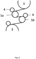
- the Figure 2 shows the device for changing the length (4) of the stretching system in detail.
- the film web (1) is moved over a first stretching roller (5 a) to the second stretching roller (5 b) guided.
- the stretching gap (6) is located between the stretching rollers (5 a) and (5 b).
- the 2 stretching rollers (5 b) have a higher circumferential speed than the first stretching roller (5 a) so that there is a positive change in length of the film web.
- the lay-on rollers (11) serve to additionally fix the film web (1) on the stretching rollers (5 a) and (5 b).
- the film web (1) then leaves the device (4) according to the invention.
- the forging roller (5b) is designed as a roller through which air flows and with the possibility of being connected to a vacuum source, not shown here.
- the forging roll (5 a) and the forging roll (5 b) can also be designed as temperature control rolls.
- the forging roller (5 b) is a combination of a roller through which air flows and a temperature control roller.
- individual or all lay-on rollers (11) can be omitted.
- Stretching systems can also have more than two stretching rollers (5) and thus have several devices (4).
- the stretching system can each have 2, 3 or more heating, stretching, annealing or cooling rollers.
Landscapes
- Engineering & Computer Science (AREA)
- Mechanical Engineering (AREA)
- Shaping By String And By Release Of Stress In Plastics And The Like (AREA)
- Processing And Handling Of Plastics And Other Materials For Molding In General (AREA)
- Registering, Tensioning, Guiding Webs, And Rollers Therefor (AREA)
- Extrusion Moulding Of Plastics Or The Like (AREA)
- Shaping Of Tube Ends By Bending Or Straightening (AREA)
- Advancing Webs (AREA)
Applications Claiming Priority (1)
| Application Number | Priority Date | Filing Date | Title |
|---|---|---|---|
| DE102020000334.6A DE102020000334A1 (de) | 2020-01-21 | 2020-01-21 | Vorrichtung und Verfahren zur monaxialen Längenänderung von Folienbahnen |
Publications (3)
| Publication Number | Publication Date |
|---|---|
| EP3854568A2 true EP3854568A2 (fr) | 2021-07-28 |
| EP3854568A3 EP3854568A3 (fr) | 2021-11-03 |
| EP3854568B1 EP3854568B1 (fr) | 2025-03-19 |
Family
ID=74191530
Family Applications (1)
| Application Number | Title | Priority Date | Filing Date |
|---|---|---|---|
| EP21000011.3A Active EP3854568B1 (fr) | 2020-01-21 | 2021-01-18 | Dispositif et procédé de changement monoaxial de la longueur des feuilles continues |
Country Status (9)
| Country | Link |
|---|---|
| US (1) | US12330364B2 (fr) |
| EP (1) | EP3854568B1 (fr) |
| JP (1) | JP7216124B2 (fr) |
| CN (1) | CN113211772B (fr) |
| CA (1) | CA3106631C (fr) |
| DE (1) | DE102020000334A1 (fr) |
| ES (1) | ES3027785T3 (fr) |
| MX (1) | MX2021000885A (fr) |
| PL (1) | PL3854568T3 (fr) |
Families Citing this family (8)
| Publication number | Priority date | Publication date | Assignee | Title |
|---|---|---|---|---|
| DE102018008127B4 (de) | 2018-10-13 | 2022-06-09 | Hosokawa Alpine Aktiengesellschaft | Blaskopf und Verfahren zur Herstellung einer Mehrschichtschlauchfolie |
| DE102018009632B4 (de) | 2018-12-11 | 2021-12-09 | Hosokawa Alpine Aktiengesellschaft | Vorrichtung zum Aufwickeln und Wickelwechsel von bahnförmigem Material und ein Verfahren dafür |
| DE102020000334A1 (de) | 2020-01-21 | 2021-07-22 | Hosokawa Alpine Aktiengesellschaft | Vorrichtung und Verfahren zur monaxialen Längenänderung von Folienbahnen |
| DE102020007806A1 (de) * | 2020-03-20 | 2021-09-23 | Windmöller & Hölscher Kg | Streckvorrichtung sowie ein Verfahren zum Verstrecken einer Kunststofffolie in ihrer Transportrichtung |
| DE102022000351A1 (de) | 2022-01-29 | 2023-08-03 | Hosokawa Alpine Aktiengesellschaft | Verfahren und Vorrichtung zur Foliendickenregelung von gereckter im Folienblasverfahren hergestellter Schlauchfolie |
| DE102022003846B4 (de) | 2022-10-17 | 2025-08-21 | Hosokawa Alpine Aktiengesellschaft | Vorrichtung zum Recken von Folienbahnen in Maschinenrichtung mit mehreren Walzen aufweisend eine Schnellwechselvorrichtung zum Wechseln von Walzen sowie Verfahren zum Walzenwechsel bei Reckanlagen mittels Schnellwechselvorrichtung |
| DE202022002610U1 (de) | 2022-10-17 | 2023-02-07 | Hosokawa Alpine Aktiengesellschaft | Vorrichtung zum Recken von Folienbahnen in Maschinenrichtung mit Schnellwechselvorrichtung für Walzen |
| DE202022002614U1 (de) | 2022-10-17 | 2023-05-11 | Hosokawa Alpine Aktiengesellschaft | Vorrichtung zum Recken von Folienbahnen in Maschinenrichtung mit Reinigungseinrichtung |
Citations (4)
| Publication number | Priority date | Publication date | Assignee | Title |
|---|---|---|---|---|
| DE102009033171A1 (de) | 2009-07-13 | 2011-01-27 | Hosokawa Alpine Ag | Verfahren zur Dickenregelung von gereckter Blasfolie |
| DE102009046593A1 (de) | 2009-11-10 | 2011-05-12 | Windmöller & Hölscher Kg | Vorrichtung und Verfahren zum Längsrecken einer Folienbahn |
| DE102009046585A1 (de) | 2009-11-10 | 2011-05-19 | Windmöller & Hölscher Kg | Vorrichtung und Verfahren zum Längsrecken einer Folienbahn |
| DE102011085735A1 (de) | 2011-11-03 | 2013-05-08 | Windmöller & Hölscher Kg | Reckwerk und Verfahren zum Längen von Folienbahnen |
Family Cites Families (147)
| Publication number | Priority date | Publication date | Assignee | Title |
|---|---|---|---|---|
| DE291871C (fr) | ||||
| US2206981A (en) | 1938-07-13 | 1940-07-09 | Sturtevant Mill Co | Air separator |
| US2285375A (en) * | 1941-06-13 | 1942-06-02 | Andrews And Goodrich Inc | Ribbed roll for slashing machines and other textile machines |
| US2780443A (en) | 1953-12-15 | 1957-02-05 | Armstrong Cork Co | Calender roll |
| AT304058B (de) | 1966-04-22 | 1972-12-27 | Exxon Research Engineering Co | Verfahren und Vorrichtung zur Herstellung von transparenten Schlauchfolien |
| NO126423B (fr) | 1970-10-09 | 1973-02-05 | Thordarson Jon | |
| DE2132098A1 (de) | 1971-06-28 | 1973-01-18 | Windmoeller & Hoelscher | Kuehlvorrichtung fuer mittels eines folienblaskopfes hergestellte kunststoff-schlauchfolien |
| US3770124A (en) | 1971-12-21 | 1973-11-06 | Combustion Eng | Swing back whizzer blades for mechanical air separator |
| US3809515A (en) | 1972-03-03 | 1974-05-07 | Farrell Patent Co | Extrusion die for blowing plastic film |
| US4003973A (en) * | 1972-06-23 | 1977-01-18 | Kabushiki Kaisha Kohjin | Process and apparatus for producing sheet film from tubular thermoplastic resin film |
| DE2250151B2 (de) | 1972-10-13 | 1975-07-31 | Barmag Barmer Maschinenfabrik Ag, 5600 Wuppertal | StrangpreBkopf zum Herstellen einer mehrschichtigen Schlauchfolie |
| US3962023A (en) | 1974-07-17 | 1976-06-08 | Mackenzie Trading Co. Ltd. | Apparatus for applying handles to plastic bags |
| DE2555848A1 (de) | 1975-12-11 | 1977-06-23 | Windmoeller & Hoelscher | Kuehlvorrichtung fuer mittels eines folienblaskopfes hergestellte kunststoff-schlauchfolien mit luftkuehlung |
| USRE33085E (en) | 1976-01-12 | 1989-10-10 | Precleaner | |
| US4018388A (en) | 1976-05-13 | 1977-04-19 | Andrews Norwood H | Jet-type axial pulverizer |
| DE2641620C3 (de) | 1976-09-16 | 1987-07-09 | Krupp Polysius Ag, 4720 Beckum | Rollenmühle mit Sichter |
| US4165356A (en) | 1978-05-15 | 1979-08-21 | Owens-Illinois, Inc. | Method of forming tubular plastic material having a flare-top edge using a blow head |
| US4277010A (en) * | 1980-04-10 | 1981-07-07 | John Dusenbery Company, Inc. | Vacuum roller for transporting a web |
| JPS5865628A (ja) | 1981-09-12 | 1983-04-19 | Toray Ind Inc | 熱可塑性シ−ト状物の成形方法 |
| DE3140294C2 (de) | 1981-10-10 | 1983-11-17 | Alpine Ag, 8900 Augsburg | Verfahren und Vorrichtung zum Trennen eines Gutgemisches in Komponenten unterschiedlicher Mahlbarkeit |
| US4510300A (en) * | 1982-04-08 | 1985-04-09 | E. I. Du Pont De Nemours And Company | Perfluorocarbon copolymer films |
| JPS59169818A (ja) | 1983-03-16 | 1984-09-25 | Toray Ind Inc | 二軸配向フイルムおよびその製造方法 |
| DE3316656A1 (de) * | 1983-05-06 | 1984-11-08 | Fritz 7347 Bad Überkingen Stahlecker | Vorrichtung zum oe-friktionsspinnen |
| DE3338138C2 (de) | 1983-10-20 | 1986-01-16 | Alpine Ag, 8900 Augsburg | Fließbett-Gegenstrahlmühle |
| JPS60141229U (ja) | 1984-02-28 | 1985-09-19 | 酒井美化工業株式会社 | 発泡シ−ト |
| DE3425101A1 (de) | 1984-07-07 | 1986-01-16 | Heinz 4630 Bochum Jäger | Verfahren und sichter zur trennscharfen sichtung eines gutstromes, insbesondere von zement |
| CN1004339B (zh) | 1985-06-29 | 1989-05-31 | 阿莱德公司 | 运动细丝钳位和切割联合系统 |
| DE68913624T2 (de) * | 1988-07-05 | 1994-10-06 | Agfa Gevaert Nv | Verfahren zum Regeln des Aufrollens von photographischem Material. |
| JP2619271B2 (ja) * | 1988-08-11 | 1997-06-11 | 富士写真フイルム株式会社 | フィルム延伸方法 |
| SU1615113A1 (ru) | 1989-01-12 | 1990-12-23 | Предприятие П/Я М-5064 | Устройство дл намотки ленточного материала |
| JP2674185B2 (ja) | 1989-02-28 | 1997-11-12 | 三菱樹脂株式会社 | 多層環状口金 |
| FI97245C (fi) | 1989-12-12 | 1996-11-11 | Valmet Paper Machinery Inc | Paperikoneen imutela |
| FR2658096B1 (fr) | 1990-02-13 | 1992-06-05 | Fives Cail Babcock | Selecteur a air a action centrifuge. |
| US5043036A (en) * | 1990-03-30 | 1991-08-27 | Minnesota Mining And Manufacturing Company | Width stretching device |
| WO1991018813A1 (fr) | 1990-06-08 | 1991-12-12 | Beloit Corporation | Dispositif de bobinage pour machines a decouper a roulettes du type a cylindre d'appui ou similaire |
| DE4100338A1 (de) | 1991-01-08 | 1992-07-09 | Nied Roland | Verfahren zum ermitteln des grades der befuellung eines behaelters |
| DE4109369A1 (de) | 1991-03-22 | 1992-09-24 | Reifenhaeuser Masch | Werkzeugkopf zum strangpressen von schlauchfoermigen oder rohrfoermigen vorformlingen aus thermoplastifiziertem kunststoff |
| DE4116964C2 (de) | 1991-05-24 | 1994-03-31 | Hans Heuser Maschinen Und Mess | Rollenschneid- und Wickelmaschine |
| DE4140656C1 (fr) | 1991-12-10 | 1992-09-10 | Alpine Ag, 8900 Augsburg, De | |
| JP2822758B2 (ja) | 1992-03-19 | 1998-11-11 | 株式会社村田製作所 | サクションロール |
| US5506046A (en) * | 1992-08-11 | 1996-04-09 | E. Khashoggi Industries | Articles of manufacture fashioned from sheets having a highly inorganically filled organic polymer matrix |
| JPH0664039A (ja) | 1992-08-20 | 1994-03-08 | Mitsui Petrochem Ind Ltd | 2軸延伸フィルムの製造方法及び製造装置、並びにシュリンクフィルム |
| DE9214651U1 (de) | 1992-10-28 | 1993-02-18 | Windmöller & Hölscher, 4540 Lengerich | Blasfolienextrusionskopf |
| NO176507C (no) | 1992-12-01 | 1995-04-19 | Sinvent Sintef Gruppen | Rotor for klassifiserings-apparat |
| US5370327A (en) | 1993-05-06 | 1994-12-06 | Beloit Technologies, Inc. | Method and apparatus for reeling a wound web roll |
| AT402056B (de) | 1993-08-18 | 1997-01-27 | Chemiefaser Lenzing Ag | Wickelmaschine |
| DE4405462C1 (de) | 1994-02-21 | 1995-04-20 | Windmoeller & Hoelscher | Folienblaskopf zur Extrusion eines Schlauches aus thermoplastischer Kunststoffschmelze |
| RU2128617C1 (ru) | 1994-06-16 | 1999-04-10 | Фабио Перини С.П.А. | Перемоточный станок для образования рулона ленточного материала |
| US5558930A (en) | 1994-06-23 | 1996-09-24 | Tredegar Industries, Inc. | Heat sealable, high moisture barrier film and method of making same |
| US5544841A (en) | 1994-08-18 | 1996-08-13 | Beloit Technologies, Inc. | Method and apparatus for reeling a traveling web into a wound web roll |
| WO1996026067A1 (fr) * | 1995-02-21 | 1996-08-29 | Serrot Corporation | Membrane thermoplastique monolithique renforcee par des mailles de tissu |
| DE19507799C2 (de) | 1995-03-06 | 1997-04-30 | Kleinewefers Ramisch Gmbh | Vorrichtung zum kontinuierlichen Aufwickeln von bahnförmigem Wickelgut |
| DE29505311U1 (de) | 1995-03-29 | 1995-06-01 | Omya GmbH, 50968 Köln | Zentrifugalkraftsichter |
| CA2219022A1 (fr) | 1995-04-24 | 1996-10-31 | Black Clawson Sano Inc. | Matrice a extrusion |
| CA2191630A1 (fr) | 1995-12-14 | 1997-06-15 | Surendra M. Sagar | Filiere annulaire de co-extrusion |
| US5673870A (en) | 1995-12-19 | 1997-10-07 | Beloit Technologies, Inc. | Method and apparatus for reeling a traveling paper web |
| DE19613902C2 (de) | 1996-04-06 | 1998-08-06 | Hosokawa Alpine Ag | Windsichter mit steifem Sichterradgrundkörper |
| US5769362A (en) | 1996-05-01 | 1998-06-23 | Safe Flight Instrument Corporation | Aircraft control mechanism for a speed brake |
| WO1998017459A1 (fr) | 1996-10-22 | 1998-04-30 | Schirmer Henry G | Matrice de coextrusion a disques modulaires |
| ATE290504T1 (de) | 1997-01-25 | 2005-03-15 | Voith Paper Patent Gmbh | Wickelmaschine und verfahren zum kontinuierlichen aufwickeln einer materialbahn |
| JP3744120B2 (ja) | 1997-05-23 | 2006-02-08 | 川上産業株式会社 | プラスチック気泡シートの製造方法および製造装置 |
| DE19728382C2 (de) | 1997-07-03 | 2003-03-13 | Hosokawa Alpine Ag & Co | Verfahren und Vorrichtung zur Fließbett-Strahlmahlung |
| RU2124465C1 (ru) | 1997-11-26 | 1999-01-10 | Манулик Сергей Николаевич | Перемоточный станок для намотки в рулон ленточных материалов |
| DE19755357A1 (de) | 1997-12-12 | 1999-06-24 | Freudenberg Carl Fa | Portal-Tragwalzenwickler zur stillstandsfreien Aufwicklung bahnförmiger Materialien |
| ATE290041T1 (de) | 1997-12-19 | 2005-03-15 | Trexel Inc | Mikrozellulares schaumstoff- extrusions/blasformverfahren und damit hergestellter gegenstand |
| FI110424B (fi) | 1998-06-18 | 2003-01-31 | Metso Paper Inc | Rullain ja menetelmä rainan rullaamiseksi |
| DE19840344C2 (de) | 1998-09-04 | 2002-04-04 | Hosokawa Alpine Ag & Co | Sichtrad für einen Zentrifugalkraft-Windsichter |
| US6189821B1 (en) | 1999-03-25 | 2001-02-20 | Raymond James | Apparatus for plastic particle reduction using dove-tailed blade |
| US6398139B1 (en) | 1999-08-23 | 2002-06-04 | Roland Nied | Process for fluidized-bed jet milling, device for carrying out this process and unit with such a device for carrying out this process |
| DE20022174U1 (de) | 1999-09-09 | 2001-05-17 | Kdesign GmbH, 51371 Leverkusen | Vorrichtung zur Steuerung und Regelung des Dickenprofils bei der Blasfolienherstellung |
| DE10029175B4 (de) | 1999-09-09 | 2004-10-07 | Kdesign Gmbh | Verfahren und Vorrichtung zur Steuerung und Regelung des Dickenprofils bei der Blasfolienherstellung |
| JP3052086B1 (ja) | 1999-09-16 | 2000-06-12 | 株式会社不二鉄工所 | 2軸直動型巻取機 |
| DE10033628A1 (de) | 2000-07-11 | 2002-01-24 | Hosokawa Alpine Ag & Co | Fliessbett-Gegenstrahlmühle |
| DE10059306C1 (de) | 2000-11-29 | 2002-05-16 | Reifenhaeuser Masch | Werkzeugkopf zur Extrusion eines rohrförmigen Stranges aus mindestens einer thermoplastischen Kunststoffschmelze für die Herstellung von Blasfolien |
| JP2003072997A (ja) | 2001-08-31 | 2003-03-12 | Fuji Photo Film Co Ltd | サクションローラ |
| DE20117248U1 (de) | 2001-10-24 | 2003-03-06 | Reinhold, Klaus, 49525 Lengerich | Vorrichtung zum Aufwickeln von Materialbahnen |
| JP4203271B2 (ja) | 2002-06-21 | 2008-12-24 | 岡崎機械工業株式会社 | サクションローラ |
| EP1433730B1 (fr) | 2002-10-25 | 2007-01-10 | Reifenhäuser GmbH & Co. Maschinenfabrik | Dispositif pour enrouler et méthode pour changer un mandarin d'enroulage dans une enrouleuse |
| DE10257496B3 (de) * | 2002-12-10 | 2004-10-14 | Bachofen & Meier Ag | Vakuum-Kühlwalze |
| US7028931B2 (en) | 2003-11-03 | 2006-04-18 | Riley Power, Inc. | Dynamic ring classifier for a coal pulverizer |
| JP4390254B2 (ja) * | 2003-12-01 | 2009-12-24 | 富士フイルム株式会社 | 溶液製膜方法及びフィルム |
| DE102004004084A1 (de) | 2004-01-27 | 2005-08-18 | Treofan Germany Gmbh & Co.Kg | Verfahren und Vorrichtung zum Längsstrecken einer Folienbahn |
| US7255301B2 (en) | 2004-03-01 | 2007-08-14 | Andritz Tissue Inc. | Reel spool storage and loading device and method |
| US7897078B2 (en) * | 2004-03-09 | 2011-03-01 | 3M Innovative Properties Company | Methods of manufacturing a stretched mechanical fastening web laminate |
| US7913851B2 (en) | 2004-04-19 | 2011-03-29 | Jin-Hong Chang | Separator for grinding mill |
| DE102004040151B4 (de) | 2004-08-19 | 2008-08-21 | Hosokawa Alpine Ag | Folienblaskopf für die Herstellung von Schlauchfolien |
| JP5048646B2 (ja) | 2006-02-24 | 2012-10-17 | 太平洋セメント株式会社 | 遠心式空気分級機 |
| KR20080113392A (ko) | 2006-03-01 | 2008-12-30 | 가부시키가이샤 가네카 | 다층 폴리이미드 필름의 제조 방법 |
| DE102006048850A1 (de) | 2006-10-16 | 2008-04-17 | Evonik Degussa Gmbh | Amorphe submicron Partikel |
| GB0613969D0 (en) | 2006-07-13 | 2006-08-23 | Rasmussen O B | A method and apparatus for manufacturing a transversely oriented film of thermoplastic polymer material and products obtainable by such method |
| DE102006044833B4 (de) | 2006-09-20 | 2010-01-21 | Babcock Borsig Service Gmbh | Zentrifugalsichter und Verfahren zum Sichten |
| EP1947043B1 (fr) | 2007-01-18 | 2010-11-03 | Reifenhäuser GmbH & Co. KG Maschinenfabrik | Dispositif d'enroulement |
| JP5186267B2 (ja) | 2007-04-04 | 2013-04-17 | 富士フイルム株式会社 | セルロースアシレートフイルム及びその製造方法、並びに、偏光板、液晶表示板用光学補償フイルム、反射防止フイルム及び液晶表示装置 |
| JP2009083322A (ja) | 2007-09-28 | 2009-04-23 | Fujifilm Corp | 環状オレフィン系樹脂フィルム及びその製造方法 |
| GB0721410D0 (en) | 2007-10-31 | 2007-12-12 | Rasmussen O B | Method and apparatus for longitudinal orientation of thermoplastic film material |
| JP4362790B2 (ja) | 2008-04-11 | 2009-11-11 | 株式会社不二鉄工所 | 二軸ノーロスワインダー |
| FI121303B (fi) | 2008-07-03 | 2010-09-30 | Metso Paper Inc | Kuiturainan pituusleikkurijärjestely ja menetelmä kuiturainan pituusleikkaamiseksi |
| DE202008012076U1 (de) | 2008-09-11 | 2008-11-27 | ETEC Gesellschaft für technische Keramik mbH | Verschleißschutz-Flächenelement |
| US20100072655A1 (en) | 2008-09-23 | 2010-03-25 | Cryovac, Inc. | Die, system, and method for coextruding a plurality of fluid layers |
| US8876512B2 (en) | 2008-09-23 | 2014-11-04 | Cryovac, Inc. | Die for coextruding a plurality of fluid layers |
| CN201280352Y (zh) | 2008-09-28 | 2009-07-29 | 沙市轻工机械有限公司 | 高速自动接纸退纸机 |
| US8231007B2 (en) | 2009-01-29 | 2012-07-31 | Wark Rickey E | Static classifier cage |
| FR2941389B1 (fr) | 2009-01-29 | 2011-10-14 | Fives Fcb | Dispositif de separation granulometrique selective de matieres pulverulentes solides, a action centrifuge, et procede d'utilisation d'un tel dispositif |
| CN101987703B (zh) | 2009-07-30 | 2012-08-29 | 全利机械股份有限公司 | 薄纸卷绕机预卷纸张截断机构及其方法 |
| JP2011051782A (ja) | 2009-09-04 | 2011-03-17 | Newlong Seimitsu Kogyo Co Ltd | サクションローラユニット及び印刷機 |
| US20110229722A1 (en) | 2010-03-18 | 2011-09-22 | Cryovac, Inc. | Multilayer Oxygen Barrier Film Comprising a Plurality of Adjoining Microlayers Comprising Ethylene/Vinyl Alcohol Copolymer |
| JP5812668B2 (ja) | 2010-05-14 | 2015-11-17 | 三菱日立パワーシステムズ株式会社 | 回転式分級機 |
| JP5701679B2 (ja) * | 2010-09-03 | 2015-04-15 | 日東電工株式会社 | 矩形形状のパネルに偏光膜を有する光学フィルムを順次的に貼り付ける方法及び装置 |
| JP2013129169A (ja) | 2011-12-22 | 2013-07-04 | Idemitsu Unitech Co Ltd | 二軸延伸ナイロンフィルムの製造方法 |
| US8870561B2 (en) | 2012-03-16 | 2014-10-28 | Bbs Corporation | Layer sequence repeater module for a modular disk co-extrusion die and products thereof |
| JP2013245105A (ja) | 2012-05-29 | 2013-12-09 | Fuji Iron Works Co Ltd | シート巻取装置 |
| DE102012015462A1 (de) | 2012-08-07 | 2014-02-13 | Reifenhäuser GmbH & Co. KG Maschinenfabrik | Blasfolienanlage, Verfahren zum Herstellen einer Blasfolienbahn und damit hergestellte Folie |
| TW201425813A (zh) | 2012-12-26 | 2014-07-01 | Hon Hai Prec Ind Co Ltd | 光學透鏡以及應用該光學透鏡的發光元件 |
| JP5819876B2 (ja) | 2013-03-26 | 2015-11-24 | 富士フイルム株式会社 | 延伸フィルムの製造方法 |
| DE102013007669A1 (de) * | 2013-05-02 | 2014-11-06 | Windmöller & Hölscher Kg | Verfahren zur Regelung des Dickenprofils von inline gereckten Folien |
| DE202013012786U1 (de) | 2013-07-19 | 2019-08-02 | Windmöller & Hölscher Kg | Vorrichtung zur Herstellung von inline gereckten Folien |
| DE102013016898A1 (de) | 2013-10-13 | 2015-04-16 | Reifenhäuser GmbH & Co. KG Maschinenfabrik | Innenkühlkörper für eine Blasfolienanlage, Blasfolienanlage mit einem solchen Innenkörper sowie Verfahren zum Betreiben einer solchen Blasfolienanlage |
| EP2873508B1 (fr) | 2013-10-15 | 2019-09-11 | Reifenhäuser GmbH & Co. KG Maschinenfabrik | Tête d'extrusion |
| DE112014004724A5 (de) | 2013-10-15 | 2016-08-25 | Reifenhäuser GmbH & Co. KG Maschinenfabrik | Verfahren zum Herstellen einer Blasfolienbahn sowie Blasfolienanlage |
| KR200472091Y1 (ko) * | 2013-11-28 | 2014-04-04 | 강호관 | 박막시트 제조장치 |
| DE112015001615B4 (de) | 2014-04-03 | 2018-04-12 | Macro Technology Ltd. | Bauteilelement für eine Co-Extrusionsdüse mit rechteckigem Zufuhrkanal und Co-Extrusionsdüse |
| JP2016044295A (ja) | 2014-08-27 | 2016-04-04 | 日東電工株式会社 | 多孔質ポリテトラフルオロエチレンシートの製造方法 |
| CN204183848U (zh) | 2014-10-17 | 2015-03-04 | 广东金明精机股份有限公司 | 多层共挤吹膜设备 |
| DE102014017556B4 (de) | 2014-11-28 | 2019-05-16 | Hosokawa Alpine Aktiengesellschaft | Innenkühlturm für Folienblasanlagen |
| TWM504084U (zh) | 2015-01-29 | 2015-07-01 | Cosmo Machinery Co Ltd | 捲筒式膜料/袋料分裝捲取裝置 |
| JP2017036146A (ja) | 2015-08-14 | 2017-02-16 | 富士フイルム株式会社 | ウェブ案内装置 |
| CN106926543A (zh) * | 2015-12-30 | 2017-07-07 | 天津市凯旋塑料制品有限公司 | 一种低收缩率塑料薄膜以及制备方法 |
| JP6192758B2 (ja) | 2016-02-24 | 2017-09-06 | 井前工業株式会社 | サクションローラ |
| US20170312968A1 (en) * | 2016-04-28 | 2017-11-02 | Clopay Plastic Products Company, Inc. | Printed breathable and microporous thin thermoplastic film |
| CN205634333U (zh) | 2016-05-19 | 2016-10-12 | 天津市禹神建筑防水材料有限公司 | 一种防水卷材的收卷切割系统 |
| EP3266586B1 (fr) | 2016-07-06 | 2021-09-22 | Reifenhäuser GmbH & Co. KG Maschinenfabrik | Outil multicouches |
| DE102016012388A1 (de) | 2016-10-18 | 2018-04-19 | Reifenhäuser GmbH & Co. KG Maschinenfabrik | Verteilerplattenpaket für einen blaskopf einer blasfolienanlage, blaskopf, verfahren zum herstellen einer folie im blasfolienverfahren, verfahren zum umrüsten eines blaskopfes sowie blasfolienanlage |
| DE102016012424A1 (de) | 2016-10-18 | 2018-04-19 | Reifenhäuser GmbH & Co. KG Maschinenfabrik | Verfahren zum Betreiben einer Blasfolienanlage, Verwendung eines Verfahrens zum Betreiben einer Blasfolienanlage, Blasfolienanlage und Abquetschwalze |
| DE102016012389A1 (de) | 2016-10-18 | 2018-04-19 | Reifenhäuser GmbH & Co. KG Maschinenfabrik | Blasfolienanlage und Verfahren zum Betreiben einer Blasfolienanlage zum Herstellen einer Folienbahn aus thermoplastischem Kunststoff |
| JP6622680B2 (ja) | 2016-10-31 | 2019-12-18 | 東レエンジニアリング株式会社 | 縦延伸装置 |
| DE102016015051B4 (de) | 2016-12-16 | 2019-01-31 | Hosokawa Alpine Aktiengesellschaft | Sichtrad für einen Zentrifugalkraft-Windsichter |
| JP6916085B2 (ja) | 2017-10-24 | 2021-08-11 | 株式会社アイシン | 車両用ヘッドレスト制御装置 |
| DE102018008127B4 (de) | 2018-10-13 | 2022-06-09 | Hosokawa Alpine Aktiengesellschaft | Blaskopf und Verfahren zur Herstellung einer Mehrschichtschlauchfolie |
| DE102018009632B4 (de) | 2018-12-11 | 2021-12-09 | Hosokawa Alpine Aktiengesellschaft | Vorrichtung zum Aufwickeln und Wickelwechsel von bahnförmigem Material und ein Verfahren dafür |
| DE102019107335B4 (de) | 2019-01-11 | 2024-11-07 | Reifenhäuser GmbH & Co. KG Maschinenfabrik | Vorrichtung und verfahren zur herstellung einer folienbahn |
| DE102019215492B4 (de) | 2019-10-09 | 2025-08-07 | Windmöller & Hölscher Kg | Blasfolienanlage und Verfahren zur Herstellung von Folienschläuchen oder Folienbahnen |
| DE102019215875A1 (de) | 2019-10-11 | 2021-04-15 | Windmöller & Hölscher Kg | Verfahren zum Starten oder Beenden einer Folienproduktion in einer Folienmaschine, Folienmaschine und Computerprogrammprodukt |
| DE102020000334A1 (de) | 2020-01-21 | 2021-07-22 | Hosokawa Alpine Aktiengesellschaft | Vorrichtung und Verfahren zur monaxialen Längenänderung von Folienbahnen |
| RU2737006C1 (ru) | 2020-06-09 | 2020-11-24 | Российская Федерация, от имени которой выступает Государственная корпорация по атомной энергии "Росатом" (Госкорпорация "Росатом") | Устройство для генерации электромагнитных возмущений в низкотемпературной магнитоактивной плазме |
| DE102020006008B3 (de) | 2020-10-01 | 2022-03-31 | Hosokawa Alpine Aktiengesellschaft | Fließbettgegenstrahlmühle zur Erzeugung feinster Partikel aus Aufgabegut geringer Schüttdichte und Verfahren dafür |
| CN116711318A (zh) | 2021-04-19 | 2023-09-05 | 深圳市大疆创新科技有限公司 | 拍摄设备及其控制方法、存储介质 |
| DE102022000351A1 (de) | 2022-01-29 | 2023-08-03 | Hosokawa Alpine Aktiengesellschaft | Verfahren und Vorrichtung zur Foliendickenregelung von gereckter im Folienblasverfahren hergestellter Schlauchfolie |
-
2020
- 2020-01-21 DE DE102020000334.6A patent/DE102020000334A1/de active Pending
-
2021
- 2021-01-18 ES ES21000011T patent/ES3027785T3/es active Active
- 2021-01-18 PL PL21000011.3T patent/PL3854568T3/pl unknown
- 2021-01-18 EP EP21000011.3A patent/EP3854568B1/fr active Active
- 2021-01-19 US US17/151,814 patent/US12330364B2/en active Active
- 2021-01-20 JP JP2021007111A patent/JP7216124B2/ja active Active
- 2021-01-20 CA CA3106631A patent/CA3106631C/fr active Active
- 2021-01-21 MX MX2021000885A patent/MX2021000885A/es unknown
- 2021-01-21 CN CN202110079982.8A patent/CN113211772B/zh active Active
Patent Citations (4)
| Publication number | Priority date | Publication date | Assignee | Title |
|---|---|---|---|---|
| DE102009033171A1 (de) | 2009-07-13 | 2011-01-27 | Hosokawa Alpine Ag | Verfahren zur Dickenregelung von gereckter Blasfolie |
| DE102009046593A1 (de) | 2009-11-10 | 2011-05-12 | Windmöller & Hölscher Kg | Vorrichtung und Verfahren zum Längsrecken einer Folienbahn |
| DE102009046585A1 (de) | 2009-11-10 | 2011-05-19 | Windmöller & Hölscher Kg | Vorrichtung und Verfahren zum Längsrecken einer Folienbahn |
| DE102011085735A1 (de) | 2011-11-03 | 2013-05-08 | Windmöller & Hölscher Kg | Reckwerk und Verfahren zum Längen von Folienbahnen |
Also Published As
| Publication number | Publication date |
|---|---|
| CA3106631C (fr) | 2025-12-16 |
| US12330364B2 (en) | 2025-06-17 |
| CN113211772B (zh) | 2024-12-13 |
| MX2021000885A (es) | 2021-07-22 |
| ES3027785T3 (en) | 2025-06-17 |
| JP2021115863A (ja) | 2021-08-10 |
| CN113211772A (zh) | 2021-08-06 |
| JP7216124B2 (ja) | 2023-01-31 |
| EP3854568A3 (fr) | 2021-11-03 |
| EP3854568B1 (fr) | 2025-03-19 |
| US20210221043A1 (en) | 2021-07-22 |
| PL3854568T3 (pl) | 2025-06-09 |
| CA3106631A1 (fr) | 2021-07-21 |
| DE102020000334A1 (de) | 2021-07-22 |
Similar Documents
| Publication | Publication Date | Title |
|---|---|---|
| EP3854568B1 (fr) | Dispositif et procédé de changement monoaxial de la longueur des feuilles continues | |
| EP2498976B1 (fr) | Procédé et dispositif d'étirage d'un film en bande | |
| DE102009033171B4 (de) | Verfahren zur Regelung der Foliendicke von verstreckten Schlauchfolien sowie Vorrichtung zur Durchführung des Verfahrens | |
| EP2498975B1 (fr) | Dispositif et procédé pour l'étirage longitudinal d'une bande de film | |
| EP2809496B1 (fr) | Banc d'étirage et procédé d'allongement d'une bande continue de film | |
| EP2991816B1 (fr) | Procédé de régulation du profil d'epaisseur de feuilles etirees en ligne | |
| EP2670577B1 (fr) | Dispositif de refroidissement et procédé de refroidissement d'un produit d'extrusion | |
| DE202020000221U1 (de) | Vorrichtung zur monoaxilen Längenänderung von Folienbahnen | |
| EP2085207A2 (fr) | Dispositif de fabrication de lamelles de soufflage | |
| DE102004004084A1 (de) | Verfahren und Vorrichtung zum Längsstrecken einer Folienbahn | |
| EP3302928B1 (fr) | Dispositif et procédé pour refroidir un film tubulaire | |
| DE102013215051A1 (de) | Fertigungsstation und Vorrichtung für eine Produktionsanlage sowie Produktionsanlage und Verfahren zur Herstellung und/oder Bearbeitung einer Folienbahn aus einem Kunststoffmaterial | |
| EP1722956B1 (fr) | Systeme d'extrusion pour feuille soufflee | |
| DE102005017184B4 (de) | Walze für die Kunststoffverarbeitung | |
| EP4045270A1 (fr) | Extrudeuse de film soufflé et méthode de production d'une bande de film | |
| DE102022003846B4 (de) | Vorrichtung zum Recken von Folienbahnen in Maschinenrichtung mit mehreren Walzen aufweisend eine Schnellwechselvorrichtung zum Wechseln von Walzen sowie Verfahren zum Walzenwechsel bei Reckanlagen mittels Schnellwechselvorrichtung | |
| DE2051980B2 (de) | Vorrichtung zum kontinuierlichen Her stellen von Kunststoffplatten, die aus einem Kunststoffgerippe bestehen | |
| DE102008035737A1 (de) | Anlegewalze für die Schmelzanlegung an einer Gießwalze | |
| EP1899137B1 (fr) | Dispositif deflecteur pour bande pelliculaire | |
| DE202022002610U1 (de) | Vorrichtung zum Recken von Folienbahnen in Maschinenrichtung mit Schnellwechselvorrichtung für Walzen | |
| WO2008099010A1 (fr) | Procédé et dispositif de fabrication d'une bande de matériau élastique | |
| DE102023135403A1 (de) | Folienaufwickelvorrichtung, Folienherstellungsanlage sowie Verfahren zum Aufwickeln einer Folienbahn | |
| WO2022161584A1 (fr) | Installation de fabrication de feuilles soufflées et procédé pour faire fonctionner une installation de fabrication de feuilles soufflées | |
| WO2021245214A1 (fr) | Procédé pour produire un substrat plan | |
| DE102020128123A1 (de) | Verfahren zum Herstellen eines flächigen Substrats |
Legal Events
| Date | Code | Title | Description |
|---|---|---|---|
| PUAI | Public reference made under article 153(3) epc to a published international application that has entered the european phase |
Free format text: ORIGINAL CODE: 0009012 |
|
| STAA | Information on the status of an ep patent application or granted ep patent |
Free format text: STATUS: THE APPLICATION HAS BEEN PUBLISHED |
|
| AK | Designated contracting states |
Kind code of ref document: A2 Designated state(s): AL AT BE BG CH CY CZ DE DK EE ES FI FR GB GR HR HU IE IS IT LI LT LU LV MC MK MT NL NO PL PT RO RS SE SI SK SM TR |
|
| PUAL | Search report despatched |
Free format text: ORIGINAL CODE: 0009013 |
|
| AK | Designated contracting states |
Kind code of ref document: A3 Designated state(s): AL AT BE BG CH CY CZ DE DK EE ES FI FR GB GR HR HU IE IS IT LI LT LU LV MC MK MT NL NO PL PT RO RS SE SI SK SM TR |
|
| RIC1 | Information provided on ipc code assigned before grant |
Ipc: B29C 55/28 20060101ALN20210927BHEP Ipc: B29C 55/06 20060101AFI20210927BHEP |
|
| STAA | Information on the status of an ep patent application or granted ep patent |
Free format text: STATUS: REQUEST FOR EXAMINATION WAS MADE |
|
| 17P | Request for examination filed |
Effective date: 20220503 |
|
| RBV | Designated contracting states (corrected) |
Designated state(s): AL AT BE BG CH CY CZ DE DK EE ES FI FR GB GR HR HU IE IS IT LI LT LU LV MC MK MT NL NO PL PT RO RS SE SI SK SM TR |
|
| STAA | Information on the status of an ep patent application or granted ep patent |
Free format text: STATUS: EXAMINATION IS IN PROGRESS |
|
| 17Q | First examination report despatched |
Effective date: 20231024 |
|
| GRAP | Despatch of communication of intention to grant a patent |
Free format text: ORIGINAL CODE: EPIDOSNIGR1 |
|
| STAA | Information on the status of an ep patent application or granted ep patent |
Free format text: STATUS: GRANT OF PATENT IS INTENDED |
|
| RIC1 | Information provided on ipc code assigned before grant |
Ipc: B29C 55/28 20060101ALN20241210BHEP Ipc: B29C 55/06 20060101AFI20241210BHEP |
|
| RIC1 | Information provided on ipc code assigned before grant |
Ipc: B29C 55/28 20060101ALN20241219BHEP Ipc: B29C 55/06 20060101AFI20241219BHEP |
|
| INTG | Intention to grant announced |
Effective date: 20250107 |
|
| GRAS | Grant fee paid |
Free format text: ORIGINAL CODE: EPIDOSNIGR3 |
|
| GRAA | (expected) grant |
Free format text: ORIGINAL CODE: 0009210 |
|
| STAA | Information on the status of an ep patent application or granted ep patent |
Free format text: STATUS: THE PATENT HAS BEEN GRANTED |
|
| AK | Designated contracting states |
Kind code of ref document: B1 Designated state(s): AL AT BE BG CH CY CZ DE DK EE ES FI FR GB GR HR HU IE IS IT LI LT LU LV MC MK MT NL NO PL PT RO RS SE SI SK SM TR |
|
| REG | Reference to a national code |
Ref country code: GB Ref legal event code: FG4D Free format text: NOT ENGLISH |
|
| REG | Reference to a national code |
Ref country code: CH Ref legal event code: EP |
|
| P01 | Opt-out of the competence of the unified patent court (upc) registered |
Free format text: CASE NUMBER: APP_8888/2025 Effective date: 20250221 |
|
| REG | Reference to a national code |
Ref country code: DE Ref legal event code: R096 Ref document number: 502021006947 Country of ref document: DE |
|
| REG | Reference to a national code |
Ref country code: IE Ref legal event code: FG4D Free format text: LANGUAGE OF EP DOCUMENT: GERMAN |
|
| REG | Reference to a national code |
Ref country code: ES Ref legal event code: FG2A Ref document number: 3027785 Country of ref document: ES Kind code of ref document: T3 Effective date: 20250617 |
|
| PG25 | Lapsed in a contracting state [announced via postgrant information from national office to epo] |
Ref country code: RS Free format text: LAPSE BECAUSE OF FAILURE TO SUBMIT A TRANSLATION OF THE DESCRIPTION OR TO PAY THE FEE WITHIN THE PRESCRIBED TIME-LIMIT Effective date: 20250619 |
|
| PG25 | Lapsed in a contracting state [announced via postgrant information from national office to epo] |
Ref country code: FI Free format text: LAPSE BECAUSE OF FAILURE TO SUBMIT A TRANSLATION OF THE DESCRIPTION OR TO PAY THE FEE WITHIN THE PRESCRIBED TIME-LIMIT Effective date: 20250319 |
|
| REG | Reference to a national code |
Ref country code: LT Ref legal event code: MG9D |
|
| PG25 | Lapsed in a contracting state [announced via postgrant information from national office to epo] |
Ref country code: NO Free format text: LAPSE BECAUSE OF FAILURE TO SUBMIT A TRANSLATION OF THE DESCRIPTION OR TO PAY THE FEE WITHIN THE PRESCRIBED TIME-LIMIT Effective date: 20250619 |
|
| PG25 | Lapsed in a contracting state [announced via postgrant information from national office to epo] |
Ref country code: HR Free format text: LAPSE BECAUSE OF FAILURE TO SUBMIT A TRANSLATION OF THE DESCRIPTION OR TO PAY THE FEE WITHIN THE PRESCRIBED TIME-LIMIT Effective date: 20250319 |
|
| PG25 | Lapsed in a contracting state [announced via postgrant information from national office to epo] |
Ref country code: LV Free format text: LAPSE BECAUSE OF FAILURE TO SUBMIT A TRANSLATION OF THE DESCRIPTION OR TO PAY THE FEE WITHIN THE PRESCRIBED TIME-LIMIT Effective date: 20250319 |
|
| PG25 | Lapsed in a contracting state [announced via postgrant information from national office to epo] |
Ref country code: BG Free format text: LAPSE BECAUSE OF FAILURE TO SUBMIT A TRANSLATION OF THE DESCRIPTION OR TO PAY THE FEE WITHIN THE PRESCRIBED TIME-LIMIT Effective date: 20250319 Ref country code: GR Free format text: LAPSE BECAUSE OF FAILURE TO SUBMIT A TRANSLATION OF THE DESCRIPTION OR TO PAY THE FEE WITHIN THE PRESCRIBED TIME-LIMIT Effective date: 20250620 |
|
| REG | Reference to a national code |
Ref country code: NL Ref legal event code: MP Effective date: 20250319 |
|
| PG25 | Lapsed in a contracting state [announced via postgrant information from national office to epo] |
Ref country code: NL Free format text: LAPSE BECAUSE OF FAILURE TO SUBMIT A TRANSLATION OF THE DESCRIPTION OR TO PAY THE FEE WITHIN THE PRESCRIBED TIME-LIMIT Effective date: 20250319 |
|
| PG25 | Lapsed in a contracting state [announced via postgrant information from national office to epo] |
Ref country code: SE Free format text: LAPSE BECAUSE OF FAILURE TO SUBMIT A TRANSLATION OF THE DESCRIPTION OR TO PAY THE FEE WITHIN THE PRESCRIBED TIME-LIMIT Effective date: 20250319 |
|
| PG25 | Lapsed in a contracting state [announced via postgrant information from national office to epo] |
Ref country code: SM Free format text: LAPSE BECAUSE OF FAILURE TO SUBMIT A TRANSLATION OF THE DESCRIPTION OR TO PAY THE FEE WITHIN THE PRESCRIBED TIME-LIMIT Effective date: 20250319 |
|
| PG25 | Lapsed in a contracting state [announced via postgrant information from national office to epo] |
Ref country code: PT Free format text: LAPSE BECAUSE OF FAILURE TO SUBMIT A TRANSLATION OF THE DESCRIPTION OR TO PAY THE FEE WITHIN THE PRESCRIBED TIME-LIMIT Effective date: 20250721 |
|
| PG25 | Lapsed in a contracting state [announced via postgrant information from national office to epo] |
Ref country code: EE Free format text: LAPSE BECAUSE OF FAILURE TO SUBMIT A TRANSLATION OF THE DESCRIPTION OR TO PAY THE FEE WITHIN THE PRESCRIBED TIME-LIMIT Effective date: 20250319 |
|
| PG25 | Lapsed in a contracting state [announced via postgrant information from national office to epo] |
Ref country code: RO Free format text: LAPSE BECAUSE OF FAILURE TO SUBMIT A TRANSLATION OF THE DESCRIPTION OR TO PAY THE FEE WITHIN THE PRESCRIBED TIME-LIMIT Effective date: 20250319 |
|
| PG25 | Lapsed in a contracting state [announced via postgrant information from national office to epo] |
Ref country code: SK Free format text: LAPSE BECAUSE OF FAILURE TO SUBMIT A TRANSLATION OF THE DESCRIPTION OR TO PAY THE FEE WITHIN THE PRESCRIBED TIME-LIMIT Effective date: 20250319 |
|
| PG25 | Lapsed in a contracting state [announced via postgrant information from national office to epo] |
Ref country code: IS Free format text: LAPSE BECAUSE OF FAILURE TO SUBMIT A TRANSLATION OF THE DESCRIPTION OR TO PAY THE FEE WITHIN THE PRESCRIBED TIME-LIMIT Effective date: 20250719 |
|
| REG | Reference to a national code |
Ref country code: DE Ref legal event code: R097 Ref document number: 502021006947 Country of ref document: DE |
|
| PGFP | Annual fee paid to national office [announced via postgrant information from national office to epo] |
Ref country code: GB Payment date: 20251204 Year of fee payment: 6 |
|
| PG25 | Lapsed in a contracting state [announced via postgrant information from national office to epo] |
Ref country code: DK Free format text: LAPSE BECAUSE OF FAILURE TO SUBMIT A TRANSLATION OF THE DESCRIPTION OR TO PAY THE FEE WITHIN THE PRESCRIBED TIME-LIMIT Effective date: 20250319 |
|
| PGFP | Annual fee paid to national office [announced via postgrant information from national office to epo] |
Ref country code: FR Payment date: 20251208 Year of fee payment: 6 |
|
| PGFP | Annual fee paid to national office [announced via postgrant information from national office to epo] |
Ref country code: PL Payment date: 20251206 Year of fee payment: 6 |
|
| PLBE | No opposition filed within time limit |
Free format text: ORIGINAL CODE: 0009261 |
|
| STAA | Information on the status of an ep patent application or granted ep patent |
Free format text: STATUS: NO OPPOSITION FILED WITHIN TIME LIMIT |
|
| REG | Reference to a national code |
Ref country code: CH Ref legal event code: L10 Free format text: ST27 STATUS EVENT CODE: U-0-0-L10-L00 (AS PROVIDED BY THE NATIONAL OFFICE) Effective date: 20260128 |
|
| 26N | No opposition filed |
Effective date: 20251222 |
|
| PGFP | Annual fee paid to national office [announced via postgrant information from national office to epo] |
Ref country code: ES Payment date: 20260213 Year of fee payment: 6 |
|
| PGFP | Annual fee paid to national office [announced via postgrant information from national office to epo] |
Ref country code: DE Payment date: 20260121 Year of fee payment: 6 |
|
| PGFP | Annual fee paid to national office [announced via postgrant information from national office to epo] |
Ref country code: AT Payment date: 20251230 Year of fee payment: 6 |
|
| PGFP | Annual fee paid to national office [announced via postgrant information from national office to epo] |
Ref country code: BE Payment date: 20260106 Year of fee payment: 6 Ref country code: IT Payment date: 20251219 Year of fee payment: 6 |
|
| PGFP | Annual fee paid to national office [announced via postgrant information from national office to epo] |
Ref country code: TR Payment date: 20260114 Year of fee payment: 6 |
|
| PGFP | Annual fee paid to national office [announced via postgrant information from national office to epo] |
Ref country code: CZ Payment date: 20260109 Year of fee payment: 6 |