EP3854577A1 - Pressvorrichtung für die herstellung von gepressten tabletten - Google Patents
Pressvorrichtung für die herstellung von gepressten tabletten Download PDFInfo
- Publication number
- EP3854577A1 EP3854577A1 EP21152751.0A EP21152751A EP3854577A1 EP 3854577 A1 EP3854577 A1 EP 3854577A1 EP 21152751 A EP21152751 A EP 21152751A EP 3854577 A1 EP3854577 A1 EP 3854577A1
- Authority
- EP
- European Patent Office
- Prior art keywords
- compaction
- press device
- assemblies
- punches
- tablets
- Prior art date
- Legal status (The legal status is an assumption and is not a legal conclusion. Google has not performed a legal analysis and makes no representation as to the accuracy of the status listed.)
- Granted
Links
Images



Classifications
-
- B—PERFORMING OPERATIONS; TRANSPORTING
- B30—PRESSES
- B30B—PRESSES IN GENERAL
- B30B11/00—Presses specially adapted for forming shaped articles from material in particulate or plastic state, e.g. briquetting presses, tabletting presses
- B30B11/02—Presses specially adapted for forming shaped articles from material in particulate or plastic state, e.g. briquetting presses, tabletting presses using a ram exerting pressure on the material in a moulding space
- B30B11/08—Presses specially adapted for forming shaped articles from material in particulate or plastic state, e.g. briquetting presses, tabletting presses using a ram exerting pressure on the material in a moulding space co-operating with moulds carried by a turntable
-
- B—PERFORMING OPERATIONS; TRANSPORTING
- B30—PRESSES
- B30B—PRESSES IN GENERAL
- B30B15/00—Details of, or accessories for, presses; Auxiliary measures in connection with pressing
- B30B15/32—Discharging presses
Definitions
- the present invention relates to the field of the design of tablets from a mixture of components, in the form of powders or granules in particular, and more particularly to a press device for forming such tablets by compaction.
- the existing devices for manufacturing tablets by compaction are conventionally rotary presses provided with a rotary central plate in which a plurality of through dies is provided.
- a rotary central plate in which a plurality of through dies is provided.
- the punches are provided with compaction ends whose surfaces define with the walls of the die a containment volume of the mixture, the punches being gradually brought together until the compaction volume is reached.
- the most productive press devices possible that is to say, making it possible to produce a high number of tablets, to meet industrial production rates, are in demand today.
- the adaptability of the press devices is also an important criterion, so that the same production site can, for example, produce several different types of tablets, while ensuring the aforementioned industrial rates.
- An aim of the present invention is therefore to provide a press device suitable for industrial production rates and making it possible to be adapted to different types of powder mixtures without this reducing productivity.
- an object of the present invention is to provide a press device which can operate at low speed while maintaining high production rates.
- a press device for manufacturing compacted tablets from at least one mixture in powder form as defined in claim 1 and in the claims which depend thereon.
- the described press device comprises a frame on which are mounted a first set of compaction and a second set of compaction distinct from the first set of compaction, the first and second sets of compaction each having a rotating plate, in which the rotating plates of the first and second compaction assemblies are mounted adjacent and configured to rotate in opposite directions of rotation, the first and second compaction assemblies each having a single shelf outlet.
- outlets of the first and second compaction assemblies are positioned on the same side with respect to the frame, that is to say on the same side with respect to a vertical plane of the frame, in particular on the side of one of the lateral edges. of the frame.
- the rotary plate has several dies each intended to receive the mixture, the dies being arranged on the periphery of said rotary plate.
- the first and second compaction assemblies also preferably each have a compaction system comprising a set of punches arranged on one side of the rotating plate, each punch being arranged opposite one of the dies of the rotating plate and mounted to move in translation. coaxially with the corresponding die and following the rotary movement of the rotary plate, the compaction system further comprising a back pressure assembly arranged on the side of the rotary plate opposite to the side where the punches are arranged, the back pressure assembly being provided to alternately close the dies and create with the punch associated with the die a closed volume of compaction.
- the figure 1 illustrates the rotary press device which is proposed according to the invention and which has the particularity of having a single frame 1 on which are mounted two sets of compaction (2; 3) distinct from one another.
- the two compaction assemblies (2; 3) can operate independently of one another, but are preferably used at the same time, or even in a synchronized manner, to promote rhythmic production.
- the compaction assemblies (2; 3) have identical structures and identical operations, but compaction assemblies with different arrangements and similar operations could be provided.
- the compaction assemblies (2; 3) can for example be arranged symmetrically with respect to a vertical plane of the frame 1.
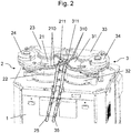
- the compaction sets (2; 3) can for example have the structure which will now be described, with reference to figures 2 to 5 .
- Each compaction assembly (2; 3) comprises a turret which is rotated by a known motorization system via a central drive axis, these drive and drive elements being for example partially positioned bottom of the frame 1 of the press device.
- the turret comprises a rotating plate (21; 31), said central plate, which comprises several compaction dies (210; 310), each die being intended to receive a mixture of compounds from which it is desired to form a tablet compacted to a volume determined.
- the rotary plate (21; 31) preferably comprises a plurality of dies (210; 310) distributed for example around the periphery of said rotary plate (21; 31) which has a substantially circular shape.
- Said dies (210; 310) have a shape adapted to the desired shape for the tablet and are either formed by a through hole made directly at the periphery of the turntable (21; 31), or each die is a specific part comprising an opening central crossing, this part serving as a die having an external shape adapted to be inserted into through openings made at the periphery of the turntable (21; 31).
- the openings forming the matrix may for example have a circular section to form substantially cylindrical shelves, or a rectangular section to form parallelepipedal shelves.
- compaction system designed to cooperate with the matrices in order to form compaction spaces, that is to say a closed volume in which the powder mixture is compressed to form a tablet.
- the compaction system can for example be formed of a set of punches (22; 32) arranged on one side of the rotating plate (21; 31) and of a back pressure assembly (23; 33) arranged on the other. side of the turntable (21; 31).
- the set of punches (22; 32) is arranged on the lower side of the turntable (21; 31), that is to say in lower part of the press device towards the frame 1, and the back pressure assembly (23; 33) is arranged on the upper side of the turntable (21; 31), that is to say in the upper part of the press device .
- the set of punches (22; 32) comprises a plurality of punches (221; 321) where each punch being arranged opposite one of the dies (210; 310) of the rotary plate (21; 31) and mounted movably in translation coaxially with the corresponding matrix.
- the punches (221; 321) are further mounted to follow the rotary movement of the turntable 1, i.e. the punches (221; 321) are mounted in the press so as to have a circular movement corresponding to the circular movement of the dies (210; 310) with which they are associated.
- a solution for setting the punches (221; 321) in motion along this circular path is to use a drive plate (222; 322) mounted in rotation with respect to the frame 1, integral and coaxial with respect to the rotary plate (21 ; 31).
- a drive plate (222; 322) is for example provided with through openings arranged at its periphery, these through openings being intended to receive the punches (221; 321) of the set of punches (22; 32).
- the punches (221; 321) are therefore driven in rotation by the drive plate (222; 322), in synchronization with the corresponding die (210; 310), the punches (221; 321) also being able to slide in the openings provided at the periphery of the drive plate (222; 322) so that the compaction ends of the punches (221; 321) can be inserted into the corresponding die (210; 310).
- the axial displacement of the punches (221; 321) is controlled by control means provided to modify the axial position of the punch (and more particularly the axial position of the compaction end of the punch) as a function of the operating cycle of the device. hurry.
- the axial position of a punch is defined as the position of the punch along the axis of the corresponding die, this position thus making it possible to characterize the axial displacement of the punch, but also the associated confinement volume in association with the back pressure assembly. .
- the compaction phase during which the punch (221; 321) is moved so as to be inserted into the corresponding die (210; 310) to reduce the volume confinement, until a final compaction volume (Vf) is reached where a final compressive force can be applied for example.
- Vf final compaction volume
- the compaction volume corresponds to the desired final volume for the tablet.
- the compaction volume is slightly less than the volume end sought for the tablet; this is the case, for example, when the compounds compressed in tablet form still exhibit a certain elasticity.
- the means for controlling the punches (221; 321) comprise a compaction cam (223; 323) having a cam path on which the punches (221; 321) are able to move, this path of cam having a path corresponding at least partially to the circular path defined by the movement of the dies (210; 310).
- the compaction can be finalized by applying a final compressive force to the powder mixture confined in the die, and there can be provided to do this a compaction roller 224 arranged in the cam track of the control cam.
- compaction 223, the compaction roller being for example mounted on a jack to apply a specific compressive force.
- the backpressure assembly (23; 33) arranged on the side of the turntable (21; 31) opposite to the side where the punches (221; 321) are arranged has the function of closing the dies (210; 310) when the phase of compaction begins and in particular when the punches (221; 321) of the set of punches (22; 32) enter the respective dies (210; 310).
- the backpressure assembly is therefore (23; 33) designed to alternately close the dies and create with the punch associated with the die a closed compaction volume.
- the back pressure assembly (23; 33) may include a compression plate (231; 331) preferably mounted flush with the corresponding rotary plate (21; 31), at the periphery of said rotary plate (21; 31) in order to be able to cover one or more adjacent dies (210; 310).
- the compression plate (231; 331) occupies a reduced space with respect to the rotary plate (21; 31) since it is not necessary for it to come and close all the dies (210; 310) of said rotary plate (21; 31), in particular it occupies a reduced surface area compared to the surface of the turntable (21; 31).
- the compression plate (231; 331) is mounted on a support (232; 333) which is fixed relative to the frame 1, so that the compression plate (231; 331) alternately covers a number of dies (210; 310) adjacent due to the rotation of the turntable (21; 31).
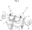
- the back pressure assembly (23; 33) is however removable relative to the frame 1 so as to be able to clear the space on the side of the turntable (21; 31) where the back pressure assembly (23) is positioned; 33).
- the back pressure assembly (23) is positioned; 33).
- it can be mounted in rotation on the frame 1 so that it can be rotated in order to freeing the upper surface of the turntable (21; 31), which in particular facilitates cleaning of the press device as explained below.
- the compression plate (231; 331) is mounted loose on the support (232; 333) so as to be able to rotate freely with respect to said support (232; 333).
- the compression plate (231; 331) has for example the shape of a disc or cylinder and is mounted in rotation with respect to the support (232; 333) by means of a shaft corresponding to the axis of revolution of the disc or cylinder.
- the fact that the compression plate (231; 331) is mounted to rotate freely with respect to the corresponding support (232; 333) is advantageous in that the compaction is fluidized, in particular avoiding any possible resistance created in contact with the powder mixture in compression.
- the figure 5 illustrates the cooperation of a punch 221 of the punch assembly 22 with the compression plate 231 of the back pressure assembly 23 in order to form with the die 210 the final volume (Vf) of compaction corresponding substantially to the desired volume for the tablet in production. It can be seen that according to this example, the final compaction volume (Vf) is reached when the punch 221 is on the compaction roller 224 which imparts the final compaction force to the powder mixture used to form the tablet.
- the back pressure assembly (23; 33) can also be formed from a set of punches, called back pressure punches. Such backpressure punches are then arranged opposite the dies of the rotary plate and mounted to move in translation coaxially with the corresponding die and according to the rotary movement of the rotary plate.
- the structure and arrangement of such a set of backpressure punches may for example be similar to the structure and arrangement of the set of punches (22; 32) described above, in particular for the use of a drive plate and a compaction cam.
- Each compaction assembly (2; 3) further comprises a powder distribution system (24; 34) provided for filling the dies (210; 310).
- the powder distribution system (24; 34) is positioned on the same side as the corresponding backpressure assembly (23; 33).
- the powder distribution system (24; 34) is arranged upstream of the backpressure assembly (23; 33) corresponding to the direction of rotation of the associated rotary plate (21; 31).
- the powder distribution system (24; 34) makes it possible to fill the dies (210; 310) of the corresponding rotary plate (21; 31) with a mixture in powder form before the compaction phase begins.
- the powder distribution system (24; 34) is removable relative to the frame 1 so as to be able to clear the space on the side of the rotary plate (21; 31) where it is positioned.
- the powder distribution system (24; 34) can be removed from the frame 1 in order to free the upper surface of the turntable (21; 31), which in particular facilitates cleaning of the press device as explained below.
- the proposed press device has the particularity of having two distinct compaction assemblies (2; 3) mounted on the same frame 1 and designed to operate independently of one another.
- each of the compaction sets (2; 3) have a single outlet (211; 311) of tablets, that is, that is to say that the compaction cycle including the filling of the dies with the powder mixture, the compaction as such and the extraction of the formed tablet is carried out over the 360 degrees of the turntable (21; 31) of the corresponding compaction set (2; 3).
- the two compaction assemblies (2; 3) are in particular mounted one beside the other on the frame 1, in an adjacent manner.
- the rotating plates (21; 31) of the two compaction assemblies (2; 3) are mounted adjacent to each other and configured to rotate in opposite directions of rotation as illustrated in figure 3 .
- the rotary plates (21; 31) of the two compaction assemblies (2; 3) are preferably directly adjacent, that is to say that there is no intermediate element placed between the two rotary plates (21; 31). In particular, there is no intermediate plate or intermediate system which would somehow connect the two rotary plates (21; 31).
- the rotary plates (21; 31) of the two compaction assemblies (2; 3) are arranged on the same plane in the frame 1, this plane corresponding to the plane of the rotary plates (21; 31).
- the rotary plates (21; 31) of the two compaction assemblies (2; 3) are identical, and in particular have the same diameter and the same number of dies.
- the two compaction assemblies (2; 3) are identical and are mounted substantially symmetrically with respect to each other on the frame 1.
- the rotating plates (21; 31) of the two compaction assemblies (2; 3) can be configured to rotate synchronously, in order to have in-phase compaction cycles where the tablets produced by the two assemblies of compaction come out at the same time, or in phase shift where the tablets produced by the two sets of compaction come out alternately.
- the outlet points (211; 311) of the two compaction assemblies (2; 3) are positioned opposite one another.
- the exit points (211; 311) of the two compaction assemblies (2; 3) are preferably positioned at the level where the distance between the rotary plates (21; 31) is the shortest in the plane of said rotary plates (21 ; 31).
- each of the two compaction assemblies (2; 3) has a single outlet (211; 311) and that these outlets (211; 311) are positioned on the same side of the frame 1, and preferably one next to the other, that is to say adjacent, simplifies the press device since it is not necessary to provide a specific conveying system to bring the tablets produced to the same point.
- the arrangement of the two compaction assemblies (2; 3) means that the tablets come out directly at substantially the same point. This is particularly advantageous because the use of tablet conveying systems leads to handling of the tablets which tends to damage them and therefore to degrade their quality.
- the shelves are directly on the correct side and in the correct center distance for post-processing, especially when the shelves are to be packed afterwards. Having outlets distant from each other would not make it possible to have these defined orientations and it would therefore be necessary for equipment to be provided to handle the shelves and position them correctly for packaging, which manipulations could degrade the quality of the tablets.
- an extraction device for the tablets, preferably operating by gravity, making it possible to guide the manufactured tablets. by each of the two compaction assemblies (2; 3) from their respective exit and towards the same extraction zone.
- extraction devices 25; 35
- maintaining the shelves in two lanes which may be advantageous depending on the configurations of the post-treatment equipment, in particular the packaging machine. It could however be envisaged extraction devices (25; 35) configured to converge the tablets towards a single path.
- the proposed press device therefore makes it possible to double the production capacity thanks to the use of two compaction assemblies in parallel while offering a simple arrangement without additional equipment, and consequently also space-saving which is very advantageous to nowadays when the problems of management and saving of space are omnipresent.
- One of the advantages of the proposed press device is that it also makes it possible to rotate more slowly than a press having a single compaction assembly, while ensuring an identical production rate.
- the proposed press device makes it possible to produce at full capacity in all cases, including for certain specific powder mixtures which require longer filling and / or compression times and / or longer compaction maintenance times. .
- the fact of reducing the speed of rotation of the turret reduces the tangential speed and increases the action times of the various functions of the press device (the functions representing angular sectors of the rotary table), which is particularly advantageous.
- the proposed press device also has advantages in terms of size. Indeed, in addition to the fact that it is not necessary to provide additional equipment for handling and / or refocusing the shelves, the proposed configuration makes it possible to have a number of stations per set of compaction (equivalent to the number of dies per turret) smaller compared to a press with a single compaction assembly and two outlets, for example, which is larger and includes a large number of stations. The diameters of the rotary plates of the proposed press device are therefore reduced and the overall size is also reduced.
- the proposed press device preferably comprises an electrical cabinet 4 positioned in the frame 1 and configured to supply the two compaction assemblies (2; 3).
- an electrical cabinet 4 positioned in the frame 1 and configured to supply the two compaction assemblies (2; 3).
- Another advantage of the proposed press device is that it is possible with a single press device to manufacture tablets in parallel according to two different compositions. To do this, it suffices to fill each powder distribution system (24; 34) with a different powder mixture, so that the tablets formed by the two sets of compaction will have different compositions.
- the punches 221 of the set of punches 22 and / or the set of backpressure 23 of the first system compaction 2 may have active compaction surfaces having different shapes from the active compaction surfaces of the punches 321 of the set of punches 32 and / or of the backpressure set 33 of the second compaction system 3, so that the tablets formed by the first and second sets of compaction will in this case have different shapes.
- the assembly and disassembly of the press device is relatively simple, which is advantageous if a part has to be changed for example.
- the parts positioned below the rotary table (21; 31) can be positioned on the frame 1 thanks to the positioning studs and / or drive axis provided for the operation of the rotary tables.
- the figure 7 illustrate the positioning of the parts positioned above the turntable (21; 31) which are also easily put in place by keying elements provided for this purpose.
- the proposed press device has the advantage of allowing easier cleaning of the press, in particular of the upper part, that is to say above the rotary plates (21; 31), which is in contact with the powder. Indeed, as illustrated in figure 8 , we see that it is very easy to free the upper space of the rotary plates (21; 31) to remove the backpressure assemblies (23; 33) as well as the powder distribution systems (24; 34).
- Press 1 used in the comparative example below corresponds to a press with a single turret and a single outlet.
- the press used in the comparative example below corresponds to a press with a single turret and double outlets, the outlets being arranged at 180 degrees from each other at the level of the turret.
- Press 3 used in the comparative example below corresponds to the press device proposed by the applicant, and corresponding to the example illustrated in the appended figures.
- the tests were carried out with the same powder mixture intended to form broth tablets.
- the press devices have been configured to obtain tablets having the same shape with the same dimensions.
- the Press 2 can have a substantially reduced tangential speed compared to the Press 1.
- Press 2 also makes it possible to ensure an extended compression maintenance time, which can in certain cases make it possible to confer increased mechanical properties on the tablets, depending on the composition of the powder mixture in particular.
- the Press 2 has a major drawback compared to the Press 1 in terms of size since it occupies a much larger floor space.
- the two outlets provided on Press 2 are arranged at 180 degrees to each other, requiring the use of ancillary equipment allowing the shelves to be refocused on one side, which further increases the bulk. of the press device. It should also be remembered that such equipment can also damage the shelves due to the manipulations which are made of them.
- the Press 3 which corresponds to the press device proposed in this document makes it possible to present all the advantages of the Press 1 and Press 2 without having the drawbacks, or even to have improved performance compared to to these two benchmark presses.
- the holding time in compression of the Press 3 is appreciably longer compared to that achieved by the Press 1.
- the holding time in compression of the Press 3 is also longer than that of the Press 2. , which is still a definite advantage in order to be able, if necessary, to improve the mechanical properties of the tablets.
- Press 3 has a greatly reduced size compared to the Press 1 and the Press 2, which is due to the general arrangement of the press device but also to the fact that the power supply device is integrated. in Press 3 while it is deported for Press 1 and Press 2. It should also be noted that Press 3 has the advantage of directly allowing the tablets to be extracted in a specific area of the press, without the need for additional equipment. This also has the advantage that the tablets do not undergo any manipulation and therefore no risk of deterioration by such equipment.
- the proposed device also makes it possible to offer greater production flexibility since it is possible to produce in parallel, with a single press device, tablets having shapes and / or different compositions.
Landscapes
- Engineering & Computer Science (AREA)
- Mechanical Engineering (AREA)
- Medical Preparation Storing Or Oral Administration Devices (AREA)
- Medicinal Preparation (AREA)
- Press Drives And Press Lines (AREA)
Applications Claiming Priority (1)
| Application Number | Priority Date | Filing Date | Title |
|---|---|---|---|
| FR2000645A FR3106524B1 (fr) | 2020-01-23 | 2020-01-23 | Dispositif de presse pour fabriquer des tablettes compactées |
Publications (3)
| Publication Number | Publication Date |
|---|---|
| EP3854577A1 true EP3854577A1 (de) | 2021-07-28 |
| EP3854577C0 EP3854577C0 (de) | 2023-06-07 |
| EP3854577B1 EP3854577B1 (de) | 2023-06-07 |
Family
ID=70295350
Family Applications (1)
| Application Number | Title | Priority Date | Filing Date |
|---|---|---|---|
| EP21152751.0A Active EP3854577B1 (de) | 2020-01-23 | 2021-01-21 | Pressvorrichtung für die herstellung von gepressten tabletten |
Country Status (3)
| Country | Link |
|---|---|
| EP (1) | EP3854577B1 (de) |
| ES (1) | ES2953385T3 (de) |
| FR (1) | FR3106524B1 (de) |
Cited By (1)
| Publication number | Priority date | Publication date | Assignee | Title |
|---|---|---|---|---|
| CN120080593A (zh) * | 2025-04-28 | 2025-06-03 | 洛阳博巨冶金辅料有限公司 | 一种萤石粉制球用压球机 |
Citations (6)
| Publication number | Priority date | Publication date | Assignee | Title |
|---|---|---|---|---|
| FR812577A (fr) * | 1936-10-27 | 1937-05-12 | Procédé servant à la fabrication de tablettes avec enrobage, en appliquant sous pression une masse d'enrobage sur les noyaux des tablettes | |
| JPS5665798U (de) * | 1979-10-26 | 1981-06-02 | ||
| WO2004007185A1 (en) * | 2002-07-15 | 2004-01-22 | I.M.A. Industria Macchine Automatiche S.P.A. | A tablet press machine |
| WO2004047120A1 (de) * | 2002-11-15 | 2004-06-03 | Ald Vacuum Technologies Aktiengesellschaft | Automatisiertes produktionsverfahren zur herstellung von kugelförmigen graphit-brenn-und absorberelementen für hochtemperatur-kernreaktoren (htr) |
| US20060254438A1 (en) * | 2005-05-12 | 2006-11-16 | Harald Romer | Rotary press |
| KR20120009211A (ko) * | 2010-07-23 | 2012-02-01 | 주식회사 세종파마텍 | 이중펀치 타정기 및 정제 성형방법 |
-
2020
- 2020-01-23 FR FR2000645A patent/FR3106524B1/fr active Active
-
2021
- 2021-01-21 ES ES21152751T patent/ES2953385T3/es active Active
- 2021-01-21 EP EP21152751.0A patent/EP3854577B1/de active Active
Patent Citations (6)
| Publication number | Priority date | Publication date | Assignee | Title |
|---|---|---|---|---|
| FR812577A (fr) * | 1936-10-27 | 1937-05-12 | Procédé servant à la fabrication de tablettes avec enrobage, en appliquant sous pression une masse d'enrobage sur les noyaux des tablettes | |
| JPS5665798U (de) * | 1979-10-26 | 1981-06-02 | ||
| WO2004007185A1 (en) * | 2002-07-15 | 2004-01-22 | I.M.A. Industria Macchine Automatiche S.P.A. | A tablet press machine |
| WO2004047120A1 (de) * | 2002-11-15 | 2004-06-03 | Ald Vacuum Technologies Aktiengesellschaft | Automatisiertes produktionsverfahren zur herstellung von kugelförmigen graphit-brenn-und absorberelementen für hochtemperatur-kernreaktoren (htr) |
| US20060254438A1 (en) * | 2005-05-12 | 2006-11-16 | Harald Romer | Rotary press |
| KR20120009211A (ko) * | 2010-07-23 | 2012-02-01 | 주식회사 세종파마텍 | 이중펀치 타정기 및 정제 성형방법 |
Cited By (1)
| Publication number | Priority date | Publication date | Assignee | Title |
|---|---|---|---|---|
| CN120080593A (zh) * | 2025-04-28 | 2025-06-03 | 洛阳博巨冶金辅料有限公司 | 一种萤石粉制球用压球机 |
Also Published As
| Publication number | Publication date |
|---|---|
| FR3106524A1 (fr) | 2021-07-30 |
| EP3854577C0 (de) | 2023-06-07 |
| FR3106524B1 (fr) | 2022-02-04 |
| EP3854577B1 (de) | 2023-06-07 |
| ES2953385T3 (es) | 2023-11-10 |
Similar Documents
| Publication | Publication Date | Title |
|---|---|---|
| FR2625461A1 (fr) | Machine a comprimer pour la production de comprimes | |
| FR2464616A1 (fr) | Dispositif et procede de montage de composants electriques sur des platines | |
| FR2458382A1 (fr) | Machine de moulage par injection de pieces composites | |
| EP2313259B1 (de) | Vorrichtung zur herstellung von tabletten durch konstantvolumenverdichtung | |
| EP3854577B1 (de) | Pressvorrichtung für die herstellung von gepressten tabletten | |
| EP2462219A2 (de) | Vorrichtung und verfahren ausgabe eines materials in eine petrischale | |
| FR3018048A1 (fr) | Unite de moulage de preformes equipee d'un porte-noyaux mobile en rotation | |
| FR2634261A1 (fr) | Procede pour former un roulement a rouleaux et roulement a rouleaux obtenu a l'aide de ce procede, notamment pour des machines a mouvement de va-et-vient et des mecaniques d'armures rotatives | |
| EP3148787A1 (de) | Mehrschichtige tablette mit aussparung, vorrichtung und verfahren zur verdichtung solch einer tablette | |
| EP1417080B1 (de) | Insbesondere für die herstellung von elektroden bestimmte giessanlage und in einer solchen anlage verwendetes verfahren | |
| WO2010146100A1 (fr) | Procédé et dispositif de fabrication de produits compactés par compaction lente | |
| EP1600285B1 (de) | Vorrichtung zur Herstellung von Pastillen durch Zusammenpressen | |
| EP0202138A1 (de) | Verfahren zur Herstellung von Mauerblöcken, Anlage zur Durchführung dieses Verfahrens und daraus hergestellter Gegenstand | |
| CH617599A5 (de) | ||
| WO1987000793A1 (fr) | Dispositif pour la compression ou le compactage de produits en vrac tels que des sciures de bois | |
| BE1011659A7 (fr) | Machine a produire des comprimes. | |
| FR2872447A1 (fr) | Dispositif de compactage de poudre pour la fabrication de pastilles | |
| FR2839054A1 (fr) | Dispositif et procede de pliage de sac gonflable pour dispositif de securite de vehicule automobile | |
| EP0574363A1 (de) | Automatische Presse zum Verdichten in Kannen | |
| BE531948A (de) | ||
| JP4916299B2 (ja) | 錠剤製造装置 | |
| BE342617A (de) | ||
| FR2943632A1 (fr) | Installation et procede de conditionnement de pieces sous forme de barrettes | |
| FR2969032A1 (fr) | Module de pressage de pastilles | |
| FR2664534A1 (fr) | Machine de gravure automatique d'objets. |
Legal Events
| Date | Code | Title | Description |
|---|---|---|---|
| PUAI | Public reference made under article 153(3) epc to a published international application that has entered the european phase |
Free format text: ORIGINAL CODE: 0009012 |
|
| STAA | Information on the status of an ep patent application or granted ep patent |
Free format text: STATUS: REQUEST FOR EXAMINATION WAS MADE |
|
| 17P | Request for examination filed |
Effective date: 20210121 |
|
| AK | Designated contracting states |
Kind code of ref document: A1 Designated state(s): AL AT BE BG CH CY CZ DE DK EE ES FI FR GB GR HR HU IE IS IT LI LT LU LV MC MK MT NL NO PL PT RO RS SE SI SK SM TR |
|
| GRAP | Despatch of communication of intention to grant a patent |
Free format text: ORIGINAL CODE: EPIDOSNIGR1 |
|
| STAA | Information on the status of an ep patent application or granted ep patent |
Free format text: STATUS: GRANT OF PATENT IS INTENDED |
|
| GRAJ | Information related to disapproval of communication of intention to grant by the applicant or resumption of examination proceedings by the epo deleted |
Free format text: ORIGINAL CODE: EPIDOSDIGR1 |
|
| STAA | Information on the status of an ep patent application or granted ep patent |
Free format text: STATUS: REQUEST FOR EXAMINATION WAS MADE |
|
| INTG | Intention to grant announced |
Effective date: 20220623 |
|
| INTC | Intention to grant announced (deleted) | ||
| GRAP | Despatch of communication of intention to grant a patent |
Free format text: ORIGINAL CODE: EPIDOSNIGR1 |
|
| STAA | Information on the status of an ep patent application or granted ep patent |
Free format text: STATUS: GRANT OF PATENT IS INTENDED |
|
| INTG | Intention to grant announced |
Effective date: 20220831 |
|
| GRAS | Grant fee paid |
Free format text: ORIGINAL CODE: EPIDOSNIGR3 |
|
| GRAA | (expected) grant |
Free format text: ORIGINAL CODE: 0009210 |
|
| STAA | Information on the status of an ep patent application or granted ep patent |
Free format text: STATUS: THE PATENT HAS BEEN GRANTED |
|
| AK | Designated contracting states |
Kind code of ref document: B1 Designated state(s): AL AT BE BG CH CY CZ DE DK EE ES FI FR GB GR HR HU IE IS IT LI LT LU LV MC MK MT NL NO PL PT RO RS SE SI SK SM TR |
|
| REG | Reference to a national code |
Ref country code: GB Ref legal event code: FG4D Free format text: NOT ENGLISH |
|
| REG | Reference to a national code |
Ref country code: CH Ref legal event code: EP Ref country code: AT Ref legal event code: REF Ref document number: 1573819 Country of ref document: AT Kind code of ref document: T Effective date: 20230615 |
|
| REG | Reference to a national code |
Ref country code: DE Ref legal event code: R096 Ref document number: 602021002587 Country of ref document: DE |
|
| U01 | Request for unitary effect filed |
Effective date: 20230707 |
|
| U07 | Unitary effect registered |
Designated state(s): AT BE BG DE DK EE FI FR IT LT LU LV MT NL PT SE SI Effective date: 20230719 |
|
| REG | Reference to a national code |
Ref country code: LT Ref legal event code: MG9D |
|
| PG25 | Lapsed in a contracting state [announced via postgrant information from national office to epo] |
Ref country code: NO Free format text: LAPSE BECAUSE OF FAILURE TO SUBMIT A TRANSLATION OF THE DESCRIPTION OR TO PAY THE FEE WITHIN THE PRESCRIBED TIME-LIMIT Effective date: 20230907 |
|
| REG | Reference to a national code |
Ref country code: ES Ref legal event code: FG2A Ref document number: 2953385 Country of ref document: ES Kind code of ref document: T3 Effective date: 20231110 |
|
| PG25 | Lapsed in a contracting state [announced via postgrant information from national office to epo] |
Ref country code: RS Free format text: LAPSE BECAUSE OF FAILURE TO SUBMIT A TRANSLATION OF THE DESCRIPTION OR TO PAY THE FEE WITHIN THE PRESCRIBED TIME-LIMIT Effective date: 20230607 Ref country code: HR Free format text: LAPSE BECAUSE OF FAILURE TO SUBMIT A TRANSLATION OF THE DESCRIPTION OR TO PAY THE FEE WITHIN THE PRESCRIBED TIME-LIMIT Effective date: 20230607 Ref country code: GR Free format text: LAPSE BECAUSE OF FAILURE TO SUBMIT A TRANSLATION OF THE DESCRIPTION OR TO PAY THE FEE WITHIN THE PRESCRIBED TIME-LIMIT Effective date: 20230908 |
|
| PG25 | Lapsed in a contracting state [announced via postgrant information from national office to epo] |
Ref country code: SK Free format text: LAPSE BECAUSE OF FAILURE TO SUBMIT A TRANSLATION OF THE DESCRIPTION OR TO PAY THE FEE WITHIN THE PRESCRIBED TIME-LIMIT Effective date: 20230607 |
|
| PG25 | Lapsed in a contracting state [announced via postgrant information from national office to epo] |
Ref country code: IS Free format text: LAPSE BECAUSE OF FAILURE TO SUBMIT A TRANSLATION OF THE DESCRIPTION OR TO PAY THE FEE WITHIN THE PRESCRIBED TIME-LIMIT Effective date: 20231007 |
|
| U20 | Renewal fee for the european patent with unitary effect paid |
Year of fee payment: 4 Effective date: 20231215 |
|
| PG25 | Lapsed in a contracting state [announced via postgrant information from national office to epo] |
Ref country code: SM Free format text: LAPSE BECAUSE OF FAILURE TO SUBMIT A TRANSLATION OF THE DESCRIPTION OR TO PAY THE FEE WITHIN THE PRESCRIBED TIME-LIMIT Effective date: 20230607 Ref country code: SK Free format text: LAPSE BECAUSE OF FAILURE TO SUBMIT A TRANSLATION OF THE DESCRIPTION OR TO PAY THE FEE WITHIN THE PRESCRIBED TIME-LIMIT Effective date: 20230607 Ref country code: RO Free format text: LAPSE BECAUSE OF FAILURE TO SUBMIT A TRANSLATION OF THE DESCRIPTION OR TO PAY THE FEE WITHIN THE PRESCRIBED TIME-LIMIT Effective date: 20230607 Ref country code: IS Free format text: LAPSE BECAUSE OF FAILURE TO SUBMIT A TRANSLATION OF THE DESCRIPTION OR TO PAY THE FEE WITHIN THE PRESCRIBED TIME-LIMIT Effective date: 20231007 Ref country code: CZ Free format text: LAPSE BECAUSE OF FAILURE TO SUBMIT A TRANSLATION OF THE DESCRIPTION OR TO PAY THE FEE WITHIN THE PRESCRIBED TIME-LIMIT Effective date: 20230607 |
|
| PG25 | Lapsed in a contracting state [announced via postgrant information from national office to epo] |
Ref country code: PL Free format text: LAPSE BECAUSE OF FAILURE TO SUBMIT A TRANSLATION OF THE DESCRIPTION OR TO PAY THE FEE WITHIN THE PRESCRIBED TIME-LIMIT Effective date: 20230607 |
|
| REG | Reference to a national code |
Ref country code: DE Ref legal event code: R097 Ref document number: 602021002587 Country of ref document: DE |
|
| PLBE | No opposition filed within time limit |
Free format text: ORIGINAL CODE: 0009261 |
|
| STAA | Information on the status of an ep patent application or granted ep patent |
Free format text: STATUS: NO OPPOSITION FILED WITHIN TIME LIMIT |
|
| 26N | No opposition filed |
Effective date: 20240308 |
|
| PG25 | Lapsed in a contracting state [announced via postgrant information from national office to epo] |
Ref country code: MC Free format text: LAPSE BECAUSE OF FAILURE TO SUBMIT A TRANSLATION OF THE DESCRIPTION OR TO PAY THE FEE WITHIN THE PRESCRIBED TIME-LIMIT Effective date: 20230607 |
|
| PG25 | Lapsed in a contracting state [announced via postgrant information from national office to epo] |
Ref country code: MC Free format text: LAPSE BECAUSE OF FAILURE TO SUBMIT A TRANSLATION OF THE DESCRIPTION OR TO PAY THE FEE WITHIN THE PRESCRIBED TIME-LIMIT Effective date: 20230607 |
|
| U20 | Renewal fee for the european patent with unitary effect paid |
Year of fee payment: 5 Effective date: 20241210 |
|
| PG25 | Lapsed in a contracting state [announced via postgrant information from national office to epo] |
Ref country code: IE Free format text: LAPSE BECAUSE OF NON-PAYMENT OF DUE FEES Effective date: 20240121 |
|
| PG25 | Lapsed in a contracting state [announced via postgrant information from national office to epo] |
Ref country code: IE Free format text: LAPSE BECAUSE OF NON-PAYMENT OF DUE FEES Effective date: 20240121 |
|
| PG25 | Lapsed in a contracting state [announced via postgrant information from national office to epo] |
Ref country code: CY Free format text: LAPSE BECAUSE OF FAILURE TO SUBMIT A TRANSLATION OF THE DESCRIPTION OR TO PAY THE FEE WITHIN THE PRESCRIBED TIME-LIMIT; INVALID AB INITIO Effective date: 20210121 |
|
| PG25 | Lapsed in a contracting state [announced via postgrant information from national office to epo] |
Ref country code: HU Free format text: LAPSE BECAUSE OF FAILURE TO SUBMIT A TRANSLATION OF THE DESCRIPTION OR TO PAY THE FEE WITHIN THE PRESCRIBED TIME-LIMIT; INVALID AB INITIO Effective date: 20210121 |
|
| PG25 | Lapsed in a contracting state [announced via postgrant information from national office to epo] |
Ref country code: TR Free format text: LAPSE BECAUSE OF FAILURE TO SUBMIT A TRANSLATION OF THE DESCRIPTION OR TO PAY THE FEE WITHIN THE PRESCRIBED TIME-LIMIT Effective date: 20230607 |
|
| U20 | Renewal fee for the european patent with unitary effect paid |
Year of fee payment: 6 Effective date: 20251211 |
|
| REG | Reference to a national code |
Ref country code: CH Ref legal event code: U11 Free format text: ST27 STATUS EVENT CODE: U-0-0-U10-U11 (AS PROVIDED BY THE NATIONAL OFFICE) Effective date: 20260201 |
|
| PGFP | Annual fee paid to national office [announced via postgrant information from national office to epo] |
Ref country code: GB Payment date: 20260127 Year of fee payment: 6 |
|
| PGFP | Annual fee paid to national office [announced via postgrant information from national office to epo] |
Ref country code: ES Payment date: 20260209 Year of fee payment: 6 |
|
| PGFP | Annual fee paid to national office [announced via postgrant information from national office to epo] |
Ref country code: CH Payment date: 20260201 Year of fee payment: 6 |