EP3854577B1 - Pressvorrichtung für die herstellung von gepressten tabletten - Google Patents
Pressvorrichtung für die herstellung von gepressten tabletten Download PDFInfo
- Publication number
- EP3854577B1 EP3854577B1 EP21152751.0A EP21152751A EP3854577B1 EP 3854577 B1 EP3854577 B1 EP 3854577B1 EP 21152751 A EP21152751 A EP 21152751A EP 3854577 B1 EP3854577 B1 EP 3854577B1
- Authority
- EP
- European Patent Office
- Prior art keywords
- compaction
- assembly
- press device
- assemblies
- rotative
- Prior art date
- Legal status (The legal status is an assumption and is not a legal conclusion. Google has not performed a legal analysis and makes no representation as to the accuracy of the status listed.)
- Active
Links
Images





Classifications
-
- B—PERFORMING OPERATIONS; TRANSPORTING
- B30—PRESSES
- B30B—PRESSES IN GENERAL
- B30B11/00—Presses specially adapted for forming shaped articles from material in particulate or plastic state, e.g. briquetting presses, tabletting presses
- B30B11/02—Presses specially adapted for forming shaped articles from material in particulate or plastic state, e.g. briquetting presses, tabletting presses using a ram exerting pressure on the material in a moulding space
- B30B11/08—Presses specially adapted for forming shaped articles from material in particulate or plastic state, e.g. briquetting presses, tabletting presses using a ram exerting pressure on the material in a moulding space co-operating with moulds carried by a turntable
-
- B—PERFORMING OPERATIONS; TRANSPORTING
- B30—PRESSES
- B30B—PRESSES IN GENERAL
- B30B15/00—Details of, or accessories for, presses; Auxiliary measures in connection with pressing
- B30B15/32—Discharging presses
Definitions
- the present invention relates to the field of the design of tablets from a mixture of components, in the form of powders or granules in particular, and more particularly a press device for forming such tablets by compaction.
- Existing devices for manufacturing tablets by compaction are conventionally rotary presses equipped with a central rotary plate in which a plurality of traversing dies are arranged. On either side and facing each of the dies are arranged lower and upper punches complementary to each other, and intended to be inserted into the corresponding die to compact the mixture it contains in order to form a compacted tablet to the desired volume.
- the punches are provided with compaction ends whose surfaces define with the walls of the matrix a confinement volume of the mixture, the punches being progressively moved closer together until the compaction volume is reached.
- An object of the present invention is therefore to provide a press device suitable for industrial speeds and making it possible to be adapted to different types of powder mixtures without this reducing productivity.
- an object of the present invention is to provide a press device which can operate at reduced speed while maintaining high production rates.
- a press device for manufacturing compacted tablets from at least one mixture in powder form as defined in claim 1 and in the claims dependent thereon.
- the press device described comprises a frame on which are mounted a first compaction assembly and a second compaction assembly separate from the first compaction assembly, the first and second compaction assemblies each having a rotary plate, in which the rotary plates of the first and second compactor assemblies are mounted adjacent and configured to rotate in opposite directions of rotation, the first and second compactor assemblies each having a single tablet outlet.
- outlets of the first and second compaction assemblies are positioned on the same side with respect to the frame, that is to say on the same side with respect to a vertical plane of the frame, in particular on the side of one of the lateral edges of the building.
- the rotary plate has several dies each intended to receive the mixture, the dies being arranged on the periphery of said rotary plate.
- the first and second compaction sets also preferably each have a compaction system comprising a set of punches arranged on one side of the rotary plate, each punch being arranged opposite one of the dies of the rotary plate and mounted movable in translation coaxially with the corresponding die and following the rotary movement of the rotary plate, the compaction system further comprising a counterpressure assembly arranged on the side of the rotary plate opposite to the side where the punches are arranged, the counterpressure assembly being provided to alternately close the dies and create with the punch associated with the die a closed volume of compaction.
- FIG. 1 illustrates the rotary press device which is proposed according to the invention which has the particularity of having a single frame 1 on which are mounted two compaction assemblies (2; 3) separate from each other.
- the two compaction assemblies (2; 3) can operate independently of each other, but are preferably used at the same time, or even in a synchronized manner to favor a clocked production.
- the compaction sets (2; 3) have identical structures and identical operations, but compaction sets could be provided with different arrangements and similar operations.
- compaction assemblies (2; 3) can for example be arranged symmetrically with respect to a vertical plane of the frame 1.
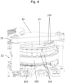
- the compaction sets (2; 3) can for example have the structure which will now be described, with reference to the figures 2 to 5 .
- Each compaction assembly (2; 3) comprises a turret which is rotated by a known motorization system via a central drive axis, these motorization and drive elements being for example positioned partly bottom of frame 1 of the press device.
- the turret comprises a rotary plate (21; 31), called the central plate, which comprises several compaction matrices (210; 310), each matrix being intended to receive a mixture of compounds from which it is desired to form a compacted tablet with a volume determined.
- the turntable (21; 31) preferably comprises a plurality of dies (210; 310) distributed for example around the periphery of said turntable (21; 31) which has a substantially circular shape.
- Said dies (210; 310) have a shape adapted to the desired shape for the tablet and are either formed by a through hole directly provided at the periphery of the rotary plate (21; 31), or each die is a specific part comprising an opening through central, this piece serving as a die having an external shape adapted to be inserted into through openings provided at the periphery of the rotary plate (21; 31).
- the openings forming the matrix can for example have a circular section to form substantially cylindrical tablets, or a rectangular section to form parallelepiped tablets.
- compaction system designed to cooperate with the matrices in order to form compaction spaces, that is to say a closed volume in which the powder mixture is compressed to form a tablet.
- the compaction system can for example be formed of a set of punches (22; 32) arranged on one side of the rotary plate (21; 31) and a set of counterpressure (23; 33) arranged on the other side of the turntable (21; 31).
- the set of punches (22; 32) is arranged on the lower side of the rotary plate (21; 31), that is to say in lower part of the press device towards the frame 1, and the counterpressure assembly (23; 33) is arranged on the upper side of the rotary plate (21; 31), that is to say in the upper part of the press device .
- the set of punches (22; 32) comprises a plurality of punches (221; 321) where each punch being arranged opposite one of the dies (210; 310) of the rotary plate (21; 31) and mounted movable in translation coaxially to the corresponding matrix.
- the punches (221; 321) are also mounted to follow the rotary movement of the rotary plate 1, that is to say the punches (221; 321) are mounted in the press so as to have a circular movement corresponding to the circular movement of the dies (210; 310) with which they are associated.
- a drive plate (222; 322) rotatably mounted relative to the frame 1, integral and coaxial relative to the rotary plate (21 ;31).
- Such a drive plate (222; 322) is for example provided with through-openings arranged at its periphery, these through-openings being intended to receive the punches (221; 321) of the set of punches (22; 32).
- the punches (221; 321) are therefore driven in rotation by the drive plate (222; 322), in a synchronized manner with the corresponding die (210; 310), the punches (221; 321) also being able to slide in the openings provided at the periphery of the drive plate (222; 322) so that the compaction ends of the punches (221; 321) can be inserted into the corresponding die (210; 310).
- the axial displacement of the punches (221; 321) is controlled by control means provided to modify the axial position of the punch (and more particularly the axial position of the compaction end of the punch) as a function of the operating cycle of the device for press.
- the axial position of a punch is defined as the position of the punch along the axis of the corresponding die, this position thus making it possible to characterize the axial displacement of the punch, but also the associated confinement volume in association with the backpressure assembly .
- the compaction phase during which the punch (221; 321) is moved so as to be inserted into the corresponding die (210; 310) to reduce the volume confinement, until reaching a final compaction volume (Vf) where a final compression force can be applied for example.
- Vf final compaction volume
- the compaction volume corresponds to the final volume sought for the tablet. It may however in some cases be possible that the volume of compaction is slightly lower than the volume end sought for the tablet; this is for example the case when the compounds compressed in tablet form still have a certain elasticity.
- the means for controlling the punches (221; 321) comprise a compaction cam (223; 323) having a cam track on which the punches (221; 321) are capable of moving, this cam having a trajectory corresponding at least partially to the circular trajectory defined by the movement of the dies (210; 310).
- the compaction can be finalized by applying a final compression force on the powder mixture confined in the matrix, and it can be provided for this purpose a compaction roller 224 arranged in the cam track of the cam of compaction 223, the compaction roller being for example mounted on a cylinder to apply a specific compression force.
- the counterpressure assembly (23; 33) arranged on the side of the rotary plate (21; 31) opposite to the side where the punches (221; 321) are arranged has the function of closing the dies (210; 310) when the phase of compaction begins and in particular when the punches (221; 321) of the set of punches (22; 32) penetrate the respective dies (210; 310).
- the backpressure assembly is therefore (23; 33) provided to alternately close the dies and create, with the punch associated with the die, a closed volume of compaction.
- the counterpressure assembly (23; 33) may comprise a compression plate (231; 331) preferably mounted flush with respect to the corresponding rotary plate (21; 31), at the periphery of said rotary plate (21; 31) in order to be able to cover one or more adjacent dies (210; 310).
- the compression plate (231; 331) occupies a reduced space compared to the rotary plate (21; 31) since it is not necessary for it to block all the dies (210; 310) of the said rotary plate (21; 31), in particular it occupies a reduced surface compared to the surface of the rotary plate (21; 31).
- the compression plate (231; 331) is mounted on a support (232; 333) which is fixed relative to the frame 1, so that the compression plate (231; 331) alternately covers a number of dies (210; 310) adjacent due to the rotation of the rotary plate (21; 31).
- the counterpressure assembly (23; 33) is however removable with respect to the frame 1 so as to be able to clear the space on the side of the rotary plate (21; 31) where the counterpressure assembly (23; 31) is positioned. 33).
- it can be rotatably mounted on the frame 1 so as to be able to be turned in order to release the upper surface of the rotary plate (21; 31), which in particular facilitates the cleaning of the press device as explained below.
- the compression plate (231; 331) is loosely mounted on the support (232; 333) so as to be able to rotate freely with respect to said support (232; 333).
- the compression plate (231; 331) has for example the shape of a disc or cylinder and is rotatably mounted relative to the support (232; 333) by means of a shaft corresponding to the axis of revolution disc or cylinder.
- the fact that the compression plate (231; 331) is mounted free to rotate with respect to the corresponding support (232; 333) is advantageous in that the compaction is fluidized, avoiding in particular any possible resistance created in contact with the powder mixture in compression.
- FIG. 5 illustrates the cooperation of a punch 221 of the punch assembly 22 with the compression plate 231 of the counterpressure assembly 23 in order to form with the matrix 210 the final volume (Vf) of compaction corresponding substantially to the volume sought for the tablet in production. It can be seen that according to this example, the final compaction volume (Vf) is reached when the punch 221 is on the compaction roller 224 which imparts the final compaction force to the powder mixture used to form the tablet.
- the counterpressure assembly (23; 33) can also be formed from a set of punches, called counterpressure punches. Such counterpressure punches are then arranged opposite the dies of the rotary plate and mounted movable in translation coaxially with the corresponding die and following the rotary movement of the rotary plate.
- the structure and arrangement of such a set of counter pressure punches can for example be similar to the structure and arrangement of the set of punches (22; 32) described above, in particular for the use of a drive plate and a compaction cam.
- Each compaction assembly (2; 3) further comprises a powder distribution system (24; 34) provided for filling the dies (210; 310).
- the powder delivery system (24; 34) is positioned on the same side as the corresponding backpressure assembly (23; 33).
- the powder distribution system (24; 34) is arranged upstream of the counterpressure assembly (23; 33) corresponding to the direction of rotation of the associated rotary plate (21; 31).
- the powder distribution system (24; 34) makes it possible to fill the dies (210; 310) of the corresponding rotary plate (21; 31) with a mixture in powder form before the compaction phase begins.
- the powder distribution system (24; 34) is removable with respect to the frame 1 so as to be able to clear the space on the side of the rotary plate (21; 31) where it is positioned.
- the powder distribution system (24; 34) can be removed from the frame 1 in order to release the upper surface of the rotary plate (21; 31), which in particular facilitates the cleaning of the press device as explained below.
- the proposed press device has the particularity of having two separate compaction assemblies (2; 3) mounted on the same frame 1 and designed to operate independently of one another.
- each of the compaction sets (2; 3) provision is made for each of the compaction sets (2; 3) to have a single output (211; 311) of shelves, this that is to say that the compaction cycle including the filling of the dies with the powder mixture, the compaction as such and the extraction of the tablet formed is carried out on the 360 degrees of the rotary plate (21; 31) of the corresponding compaction assembly (2; 3).
- the two compaction assemblies (2; 3) are in particular mounted one beside the other on the frame 1, adjacently.
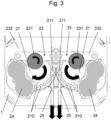
- the rotary plates (21; 31) of the two compaction assemblies (2; 3) are mounted adjacent to each other and configured to rotate in opposite directions of rotation as shown in picture 3 .
- the rotary plates (21; 31) of the two compaction assemblies (2; 3) are preferably directly adjacent, that is to say that there is no intermediate element placed between the two rotary plates (21; 31). In particular, there is no intermediate plate or intermediate system that would somehow connect the two rotary plates (21; 31).
- the rotary plates (21; 31) of the two compaction assemblies (2; 3) are arranged on the same plane in the frame 1, this plane corresponding to the plane of the rotary plates (21; 31).
- the rotary plates (21; 31) of the two compaction assemblies (2; 3) are identical, and in particular have the same diameter and the same number of dies.
- the two compaction assemblies (2; 3) are identical and are mounted substantially symmetrically with respect to each other on the frame 1.
- the rotary plates (21; 31) of the two compaction assemblies (2; 3) can be configured to rotate synchronously, in order to have compaction cycles in phase where the tablets produced by the two assemblies of compaction come out at the same time, or in phase shift where the tablets produced by the two sets of compaction come out alternately.
- the exit points (211; 311) of the two compaction assemblies (2; 3) are positioned opposite one another.
- the exit points (211; 311) of the two compaction assemblies (2; 3) are preferably positioned at the level where the distance between the rotary plates (21; 31) is the shortest in the plane of said rotary plates (21 ; 31).
- each of the two compaction assemblies (2; 3) has a single outlet (211; 311) and that these outlets (211; 311) are positioned on the same side of the frame 1, and preferably one next to the other, that is to say adjacently, makes it possible to simplify the press device since it is not necessary to provide a specific conveying system to bring the tablets produced to the same point.
- the arrangement of the two compaction assemblies (2; 3) means that the shelves come out directly at substantially the same point. This is particularly advantageous because the use of tablet conveying systems leads to manipulation of the tablets, which tends to damage them and therefore to degrade their quality.
- the tablets are directly on the right side and in the right center distance for post-processing, especially when the tablets must then be packaged. Having outputs distant from each other would not allow these orientations to be defined and it would therefore be necessary for equipment to be provided to handle the shelves and position them correctly for packaging, which manipulations could degrade the quality of the tablets.
- extraction devices 25; 35
- maintaining the tablets on two lanes which can be advantageous depending on the configurations of the post-processing equipment, in particular the packaging machine. It could however be envisaged extraction devices (25; 35) configured to make the shelves converge towards a single channel.
- the proposed press device therefore makes it possible to double the production capacity thanks to the use of two compaction sets in parallel while offering a simple layout and without additional equipment, and consequently also taking up little space, which is very advantageous to nowadays when the problems of management and gain of space are omnipresent.
- One of the advantages of the press device proposed is that it also makes it possible to rotate more slowly than a press having a single compaction assembly, while ensuring an identical production rate.
- the press device proposed makes it possible to produce at full capacity in all cases, including for certain specific powder mixtures which require longer filling and/or compression times and/or longer compaction holding times. .
- the fact of reducing the speed of rotation of the turret reduces the tangential speed and increases the action times of the various functions of the press device (the functions representing angular sectors of the rotary plate), which is particularly advantageous.
- the proposed press device also has advantages in terms of size. Indeed, in addition to the fact that it is not necessary to provide additional equipment for handling and/or refocusing the tablets, the proposed configuration makes it possible to have a number of stations per compaction set (equivalent to the number of dies per turret) smaller than a press with a single compaction assembly and two outlets, for example, which is wider and includes a large number of stations. The diameters of the rotary plates of the proposed press device are therefore reduced and the overall size is also reduced.
- the proposed press device preferably comprises an electrical cabinet 4 positioned in the frame 1 and configured to supply the two compaction assemblies (2; 3).
- an electrical cabinet 4 positioned in the frame 1 and configured to supply the two compaction assemblies (2; 3).
- Another advantage of the proposed press device is that it is possible with a single press device to manufacture tablets in parallel according to two different compositions. To do this, it suffices to fill each powder distribution system (24; 34) with a different powder mixture, so that the tablets formed by the two compaction assemblies will have different compositions.
- a further advantage is that it is possible to create with the same press device tablets also possibly having different shapes.
- the punches 221 of the set of punches 22 and/or the backpressure set 23 of the first system compaction 2 can have active compaction surfaces having different shapes from the active compaction surfaces of the punches 321 of the set of punches 32 and/or of the counterpressure set 33 of the second compaction system 3, so that the tablets formed by the first and second compaction sets will in this case have different shapes.
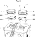
- the assembly and disassembly of the press device is relatively simple, which is advantageous if a part has to be changed, for example.
- the parts positioned below the turntable (21; 31) can be positioned on the frame 1 thanks to the positioning studs and/or drive shaft provided for the operation of the turntables.
- FIG 7 illustrate positioning of the parts positioned above the turntable (21; 31) which are also easily put in place by polarizing elements provided for this purpose.
- the proposed press device has the advantage of allowing simpler cleaning of the press, in particular of the upper part, that is to say above the rotary plates (21; 31), which is in contact with the powder. Indeed, as illustrated in figure 8 , it can be seen that it is very easy to clear the upper space of the rotary plates (21; 31) and to remove the counterpressure assemblies (23; 33) as well as the powder distribution systems (24; 34).
- Press 1 used in the comparative example below corresponds to a single turret, single output press.
- the press used in the comparative example below corresponds to a press with a single turret and double outlets, the outlets being arranged at 180 degrees from each other at the level of the turret.
- Press 3 used in the comparative example below corresponds to the press device proposed by the applicant, and corresponding to the example illustrated in the appended figures.
- the tests were carried out with the same mixture of powder intended to form tablets of bouillon.
- the press devices were configured to obtain tablets having the same shape with the same dimensions.
- Press 2 can have a substantially reduced tangential speed compared to Press 1.
- Press 2 also makes it possible to ensure an extended compression holding time, which can in certain cases make it possible to confer increased mechanical properties on the tablets, depending on the composition of the powder mixture in particular.
- Press 2 has a major disadvantage compared to Press 1 in terms of size since it takes up much more floor space.
- the two exits provided on the Press 2 are arranged at 180 degrees from each other, requiring the use of ancillary equipment allowing the shelves to be recentered on one side only, which further increases the size. of the press device. It should also be remembered that such equipment can also damage the tablets due to the manipulations that are made of them.
- Press 3 which corresponds to the press device proposed in this document, makes it possible to present all the advantages of Press 1 and Press 2 without having the disadvantages, or even to have improved performance compared to to these two reference presses.
- the holding time in compression of the Press 3 is significantly longer compared to that achieved by the Press 1.
- the holding time in compression of the Press 3 is also longer than that of the Press 2 , which is still a definite advantage in order to be able, if necessary, to improve the mechanical properties of the tablets.
- Press 3 has a greatly reduced size compared to Press 1 and Press 2, which is due to the general layout of the press device but also to the fact that the power supply device is integrated in Press 3 while it is offset for Press 1 and Press 2. It should also be noted that Press 3 has the advantage of allowing tablets to be extracted directly from a specific area of the press, without the need additional equipment. This also has the advantage that the tablets do not undergo any manipulation and therefore no risk of deterioration by such equipment.
- the proposed device also makes it possible to offer greater production flexibility since it is possible to produce in parallel, with a single and unique press device, tablets having different shapes and/or or different compositions.
Landscapes
- Engineering & Computer Science (AREA)
- Mechanical Engineering (AREA)
- Medical Preparation Storing Or Oral Administration Devices (AREA)
- Medicinal Preparation (AREA)
- Press Drives And Press Lines (AREA)
Claims (13)
- Pressvorrichtung für die Herstellung von gepressten Tabletten aus mindestens einem Gemisch in Pulverform, dadurch gekennzeichnet, dass sie ein Gestell (1) umfasst, auf dem eine erste Pressanordnung (2) und eine zweite Pressanordnung (3) angebracht sind, die sich von der ersten Pressanordnung (2) unterscheidet, wobei die erste und zweite Pressanordnung (2; 3) jeweils haben- eine rotierende Platte (21; 31) mit mehreren Matrizen (210; 310), die jeweils dazu bestimmt sind, das Gemisch aufzunehmen, wobei die Matrizen (210; 310) an der Peripherie der rotierenden Platte (21; 31) eingerichtet sind;- ein Presssystem, das eine Anordnung von Stempeln (22; 32) umfasst, die auf einer Seite der rotierenden Platte (21; 31) eingerichtet sind, wobei jeder Stempel einer der Matrizen (210; 310) der rotierenden Platte (21; 31) zugewandt eingerichtet und translatorisch beweglich koaxial zu der entsprechenden Matrize (210; 310) und gemäß der Rotationsbewegung der rotierenden Platte (21; 31) angebracht ist, wobei das Presssystem ferner eine Gegendruckanordnung (23; 33) umfasst, die auf der Seite der rotierenden Platte (21; 31) gegenüber der Seite eingerichtet ist, wo die Stempel eingerichtet sind, wobei die Gegendruckanordnung (23; 33) vorgesehen ist, um die Matrizen (210; 310) abwechselnd zu schließen und mit dem der Matrize (210; 310) zugeordneten Stempel ein geschlossenes Pressvolumen zu schaffen;dadurch gekennzeichnet, dass die rotierenden Platten (21; 31) der ersten und zweiten Pressanordnung (2; 3) angrenzend angebracht sind und ausgelegt, um in entgegengesetzten Drehrichtungen zu drehen, wobei die erste und zweite Pressanordnung (2; 3) jeweils einen einzigen Tablettenausgang (211; 311) haben, wobei die Ausgänge (211; 311) der ersten und zweiten Pressanordnung (2; 3) einander zugewandt positioniert sind.
- Pressvorrichtung nach Anspruch 1, wobei die Ausgänge (211; 311) der ersten und zweiten Pressanordnung (2; 3) an einem jeweiligen Punkt der rotierenden Platten (21; 31) positioniert sind, wo der Abstand zwischen den rotierenden Platten (21; 31) der kleinste ist.
- Pressvorrichtung nach einem der Ansprüche 1 und 2, wobei die rotierenden Platten (21; 31) der ersten und zweiten Pressanordnung (2; 3) identisch sind und vorzugsweise ausgelegt sind, um synchron zu drehen.
- Pressvorrichtung nach einem der Ansprüche 1 bis 3, wobei die rotierenden Platten (21; 31) der ersten und zweiten Pressanordnung (2; 3) auf derselben Ebene im Gestell (1) eingerichtet sind.
- Pressvorrichtung nach einem der Ansprüche 1 bis 4, wobei die Gegendruckanordnung (23; 33) von jeder der ersten und zweiten Pressanordnung (2; 3) eine Druckplatte (231; 331) umfasst, die im Verhältnis zur entsprechenden rotierenden Platte (21; 31) bündig angebracht ist.
- Pressvorrichtung nach Anspruch 5, wobei die Druckplatte (231; 331) von jeder der ersten und zweiten Pressanordnung (2; 3) im Verhältnis zum Gestell (1) lösbar ist, so dass der Raum auf der Seite der rotierenden Platte (21; 31) freigebbar ist, wo die Gegendruckanordnung (23; 33) positioniert ist.
- Pressvorrichtung nach einem der Ansprüche 1 bis 4, wobei die Gegendruckanordnung (23; 33) von jeder der ersten und zweiten Pressanordnung (2; 3) eine Anordnung von Gegendruck-Stempeln (221; 321) umfasst, wobei jeder Gegendruck-Stempel (221; 321) einer der Matrizen (210; 310) der rotierenden Platte (21; 31) zugewandt eingerichtet und translatorisch beweglich koaxial zu der entsprechenden Matrize (210; 310) und gemäß der Drehbewegung der rotierenden Platte (21; 31) eingerichtet ist.
- Pressvorrichtung nach einem der Ansprüche 1 bis 7, umfassend eine Extraktionsvorrichtung (25; 35) der Tabletten durch Schwerkraft, die es erlaubt, die von der ersten und zweiten Pressanordnung (2; 3) von deren jeweiligem Ausgang (211; 311) und zu derselben Extraktionszone zu führen.
- Pressvorrichtung nach einem der Ansprüche 1 bis 8, wobei jede von der ersten und zweiten Pressanordnung (2; 3) ein Pulververteilungssystem (24; 34) umfasst, das auf derselben Seite wie die entsprechende Gegendruckanordnung (23; 33) vor der entsprechenden Gegendruckanordnung (23; 33) im Verhältnis zur Drehrichtung der entsprechenden rotierenden Platte (21; 31) positioniert ist, wobei jedes Pulververteilungssystem (24; 34) vorgesehen ist, um die Matrizen (210; 310) der entsprechenden rotierenden Platte (21; 31) mit einem Gemisch in Pulverform zu füllen.
- Pressvorrichtung nach Anspruch 9, wobei jedes Pulververteilungssystem (24; 34) mit einem unterschiedlichen Gemisch in Pulverform gefüllt ist, so dass die von der ersten und zweiten Pressanordnung (2; 3) geformten Tabletten unterschiedliche Zusammensetzungen haben.
- Pressvorrichtung nach einem der Ansprüche 9 und 10, wobei jedes Pulververteilungssystem (24; 34) lösbar angebracht ist, so dass der Raum auf der Seite der rotierenden Platte (21; 31) freigebbar ist, wo die Gegendruckanordnung (23; 33) positioniert ist.
- Pressvorrichtung nach einem der Ansprüche 1 bis 11, wobei die Stempel der Stempelanordnung (22; 32) und/oder die Gegendruckanordnung (23; 33) des ersten Presssystems aktive Pressoberflächen haben, die Formen haben, die sich von den aktiven Pressoberflächen der Stempel der Stempelanordnung (22; 32) und/oder der Gegendruckanordnung (23; 33) des zweiten Presssystems unterscheiden, so dass die von der ersten und zweiten Pressanordnung (2; 3) geformten Tabletten unterschiedliche Formen haben.
- Pressvorrichtung nach einem der Ansprüche 1 bis 12, umfassend ferner einen Schaltschrank, der auf dem Gestell (1) positioniert und ausgelegt ist, um die erste und zweite Pressanordnung (2; 3) zu versorgen.
Applications Claiming Priority (1)
| Application Number | Priority Date | Filing Date | Title |
|---|---|---|---|
| FR2000645A FR3106524B1 (fr) | 2020-01-23 | 2020-01-23 | Dispositif de presse pour fabriquer des tablettes compactées |
Publications (3)
| Publication Number | Publication Date |
|---|---|
| EP3854577A1 EP3854577A1 (de) | 2021-07-28 |
| EP3854577B1 true EP3854577B1 (de) | 2023-06-07 |
| EP3854577C0 EP3854577C0 (de) | 2023-06-07 |
Family
ID=70295350
Family Applications (1)
| Application Number | Title | Priority Date | Filing Date |
|---|---|---|---|
| EP21152751.0A Active EP3854577B1 (de) | 2020-01-23 | 2021-01-21 | Pressvorrichtung für die herstellung von gepressten tabletten |
Country Status (3)
| Country | Link |
|---|---|
| EP (1) | EP3854577B1 (de) |
| ES (1) | ES2953385T3 (de) |
| FR (1) | FR3106524B1 (de) |
Families Citing this family (1)
| Publication number | Priority date | Publication date | Assignee | Title |
|---|---|---|---|---|
| CN120080593B (zh) * | 2025-04-28 | 2025-07-29 | 洛阳博巨冶金辅料有限公司 | 一种萤石粉制球用压球机 |
Family Cites Families (6)
| Publication number | Priority date | Publication date | Assignee | Title |
|---|---|---|---|---|
| FR812577A (fr) * | 1936-10-27 | 1937-05-12 | Procédé servant à la fabrication de tablettes avec enrobage, en appliquant sous pression une masse d'enrobage sur les noyaux des tablettes | |
| JPS5922957Y2 (ja) * | 1979-10-26 | 1984-07-09 | 株式会社 菊水製作所 | 回転式粉末圧縮成形機 |
| ITBO20020452A1 (it) * | 2002-07-15 | 2004-01-15 | Ima Spa | Macchina comprimitrice |
| DE10253205B4 (de) * | 2002-11-15 | 2005-09-15 | Ald Vacuum Technologies Ag | Automatisiertes Produktionsverfahren zur Herstellung von kugelförmigen Graphit-, Brenn- und Absorberelementen für Hochtemperatur - Kernreaktoren (HTR) |
| DE102005021926C5 (de) * | 2005-05-12 | 2008-11-20 | Fette Gmbh | Rundläuferpresse |
| KR101197188B1 (ko) * | 2010-07-23 | 2012-11-02 | 주식회사 세종파마텍 | 이중펀치 타정기 및 정제 성형방법 |
-
2020
- 2020-01-23 FR FR2000645A patent/FR3106524B1/fr active Active
-
2021
- 2021-01-21 ES ES21152751T patent/ES2953385T3/es active Active
- 2021-01-21 EP EP21152751.0A patent/EP3854577B1/de active Active
Also Published As
| Publication number | Publication date |
|---|---|
| FR3106524B1 (fr) | 2022-02-04 |
| FR3106524A1 (fr) | 2021-07-30 |
| ES2953385T3 (es) | 2023-11-10 |
| EP3854577A1 (de) | 2021-07-28 |
| EP3854577C0 (de) | 2023-06-07 |
Similar Documents
| Publication | Publication Date | Title |
|---|---|---|
| FR2625461A1 (fr) | Machine a comprimer pour la production de comprimes | |
| EP2313259B1 (de) | Vorrichtung zur herstellung von tabletten durch konstantvolumenverdichtung | |
| BE1005832A5 (fr) | Procede et appareillage de thermoformage et d'extraction d'objets creux munis d'un fond a partir d'une bande de matiere thermoplastique. | |
| EP3113925B1 (de) | Mit einem drehbaren kernhalter ausgestattete vorformformungseinheit | |
| FR2922807A1 (fr) | Fabrication en grande cadence de pieces moulees par injection | |
| EP2462219A2 (de) | Vorrichtung und verfahren ausgabe eines materials in eine petrischale | |
| FR2951989A1 (fr) | Installation pour la realisation d'un produit solide a partir d'un ou de plusieurs materiaux pulverulents | |
| EP3854577A1 (de) | Pressvorrichtung für die herstellung von gepressten tabletten | |
| BE1010547A3 (fr) | Dispositif pour enduire avec une matiere d'enduction une surface peripherique externe d'un corps de structure, en forme de colonne. | |
| FR2634261A1 (fr) | Procede pour former un roulement a rouleaux et roulement a rouleaux obtenu a l'aide de ce procede, notamment pour des machines a mouvement de va-et-vient et des mecaniques d'armures rotatives | |
| EP3148787A1 (de) | Mehrschichtige tablette mit aussparung, vorrichtung und verfahren zur verdichtung solch einer tablette | |
| WO2010146100A1 (fr) | Procédé et dispositif de fabrication de produits compactés par compaction lente | |
| FR2892051A1 (fr) | Distributeur de poudre notamment pour pastilleuse et procede de fabrication de pastilles de combustible nucleaire | |
| EP1600285B1 (de) | Vorrichtung zur Herstellung von Pastillen durch Zusammenpressen | |
| WO2003016009A1 (fr) | Installation de moulage, notamment destinee a la fabrication d'electrodes, et procede mis en oeuvre dans une telle installation | |
| FR2855094A1 (fr) | Installation pour la realisation d'un produit solide a partir d'un materiau pulverulent | |
| CH617599A5 (de) | ||
| EP0265437A1 (de) | Vorrichtung zur komprimierung oder verdichtung von losen produkten wie holzsägespänen | |
| BE1011659A7 (fr) | Machine a produire des comprimes. | |
| FR2839054A1 (fr) | Dispositif et procede de pliage de sac gonflable pour dispositif de securite de vehicule automobile | |
| FR2872447A1 (fr) | Dispositif de compactage de poudre pour la fabrication de pastilles | |
| BE531948A (de) | ||
| JP4916299B2 (ja) | 錠剤製造装置 | |
| BE342617A (de) | ||
| FR2774010A1 (fr) | Dispositif de sertissage |
Legal Events
| Date | Code | Title | Description |
|---|---|---|---|
| PUAI | Public reference made under article 153(3) epc to a published international application that has entered the european phase |
Free format text: ORIGINAL CODE: 0009012 |
|
| STAA | Information on the status of an ep patent application or granted ep patent |
Free format text: STATUS: REQUEST FOR EXAMINATION WAS MADE |
|
| 17P | Request for examination filed |
Effective date: 20210121 |
|
| AK | Designated contracting states |
Kind code of ref document: A1 Designated state(s): AL AT BE BG CH CY CZ DE DK EE ES FI FR GB GR HR HU IE IS IT LI LT LU LV MC MK MT NL NO PL PT RO RS SE SI SK SM TR |
|
| GRAP | Despatch of communication of intention to grant a patent |
Free format text: ORIGINAL CODE: EPIDOSNIGR1 |
|
| STAA | Information on the status of an ep patent application or granted ep patent |
Free format text: STATUS: GRANT OF PATENT IS INTENDED |
|
| GRAJ | Information related to disapproval of communication of intention to grant by the applicant or resumption of examination proceedings by the epo deleted |
Free format text: ORIGINAL CODE: EPIDOSDIGR1 |
|
| STAA | Information on the status of an ep patent application or granted ep patent |
Free format text: STATUS: REQUEST FOR EXAMINATION WAS MADE |
|
| INTG | Intention to grant announced |
Effective date: 20220623 |
|
| INTC | Intention to grant announced (deleted) | ||
| GRAP | Despatch of communication of intention to grant a patent |
Free format text: ORIGINAL CODE: EPIDOSNIGR1 |
|
| STAA | Information on the status of an ep patent application or granted ep patent |
Free format text: STATUS: GRANT OF PATENT IS INTENDED |
|
| INTG | Intention to grant announced |
Effective date: 20220831 |
|
| GRAS | Grant fee paid |
Free format text: ORIGINAL CODE: EPIDOSNIGR3 |
|
| GRAA | (expected) grant |
Free format text: ORIGINAL CODE: 0009210 |
|
| STAA | Information on the status of an ep patent application or granted ep patent |
Free format text: STATUS: THE PATENT HAS BEEN GRANTED |
|
| AK | Designated contracting states |
Kind code of ref document: B1 Designated state(s): AL AT BE BG CH CY CZ DE DK EE ES FI FR GB GR HR HU IE IS IT LI LT LU LV MC MK MT NL NO PL PT RO RS SE SI SK SM TR |
|
| REG | Reference to a national code |
Ref country code: GB Ref legal event code: FG4D Free format text: NOT ENGLISH |
|
| REG | Reference to a national code |
Ref country code: CH Ref legal event code: EP Ref country code: AT Ref legal event code: REF Ref document number: 1573819 Country of ref document: AT Kind code of ref document: T Effective date: 20230615 |
|
| REG | Reference to a national code |
Ref country code: DE Ref legal event code: R096 Ref document number: 602021002587 Country of ref document: DE |
|
| U01 | Request for unitary effect filed |
Effective date: 20230707 |
|
| U07 | Unitary effect registered |
Designated state(s): AT BE BG DE DK EE FI FR IT LT LU LV MT NL PT SE SI Effective date: 20230719 |
|
| REG | Reference to a national code |
Ref country code: LT Ref legal event code: MG9D |
|
| PG25 | Lapsed in a contracting state [announced via postgrant information from national office to epo] |
Ref country code: NO Free format text: LAPSE BECAUSE OF FAILURE TO SUBMIT A TRANSLATION OF THE DESCRIPTION OR TO PAY THE FEE WITHIN THE PRESCRIBED TIME-LIMIT Effective date: 20230907 |
|
| REG | Reference to a national code |
Ref country code: ES Ref legal event code: FG2A Ref document number: 2953385 Country of ref document: ES Kind code of ref document: T3 Effective date: 20231110 |
|
| PG25 | Lapsed in a contracting state [announced via postgrant information from national office to epo] |
Ref country code: RS Free format text: LAPSE BECAUSE OF FAILURE TO SUBMIT A TRANSLATION OF THE DESCRIPTION OR TO PAY THE FEE WITHIN THE PRESCRIBED TIME-LIMIT Effective date: 20230607 Ref country code: HR Free format text: LAPSE BECAUSE OF FAILURE TO SUBMIT A TRANSLATION OF THE DESCRIPTION OR TO PAY THE FEE WITHIN THE PRESCRIBED TIME-LIMIT Effective date: 20230607 Ref country code: GR Free format text: LAPSE BECAUSE OF FAILURE TO SUBMIT A TRANSLATION OF THE DESCRIPTION OR TO PAY THE FEE WITHIN THE PRESCRIBED TIME-LIMIT Effective date: 20230908 |
|
| PG25 | Lapsed in a contracting state [announced via postgrant information from national office to epo] |
Ref country code: SK Free format text: LAPSE BECAUSE OF FAILURE TO SUBMIT A TRANSLATION OF THE DESCRIPTION OR TO PAY THE FEE WITHIN THE PRESCRIBED TIME-LIMIT Effective date: 20230607 |
|
| PG25 | Lapsed in a contracting state [announced via postgrant information from national office to epo] |
Ref country code: IS Free format text: LAPSE BECAUSE OF FAILURE TO SUBMIT A TRANSLATION OF THE DESCRIPTION OR TO PAY THE FEE WITHIN THE PRESCRIBED TIME-LIMIT Effective date: 20231007 |
|
| U20 | Renewal fee for the european patent with unitary effect paid |
Year of fee payment: 4 Effective date: 20231215 |
|
| PG25 | Lapsed in a contracting state [announced via postgrant information from national office to epo] |
Ref country code: SM Free format text: LAPSE BECAUSE OF FAILURE TO SUBMIT A TRANSLATION OF THE DESCRIPTION OR TO PAY THE FEE WITHIN THE PRESCRIBED TIME-LIMIT Effective date: 20230607 Ref country code: SK Free format text: LAPSE BECAUSE OF FAILURE TO SUBMIT A TRANSLATION OF THE DESCRIPTION OR TO PAY THE FEE WITHIN THE PRESCRIBED TIME-LIMIT Effective date: 20230607 Ref country code: RO Free format text: LAPSE BECAUSE OF FAILURE TO SUBMIT A TRANSLATION OF THE DESCRIPTION OR TO PAY THE FEE WITHIN THE PRESCRIBED TIME-LIMIT Effective date: 20230607 Ref country code: IS Free format text: LAPSE BECAUSE OF FAILURE TO SUBMIT A TRANSLATION OF THE DESCRIPTION OR TO PAY THE FEE WITHIN THE PRESCRIBED TIME-LIMIT Effective date: 20231007 Ref country code: CZ Free format text: LAPSE BECAUSE OF FAILURE TO SUBMIT A TRANSLATION OF THE DESCRIPTION OR TO PAY THE FEE WITHIN THE PRESCRIBED TIME-LIMIT Effective date: 20230607 |
|
| PG25 | Lapsed in a contracting state [announced via postgrant information from national office to epo] |
Ref country code: PL Free format text: LAPSE BECAUSE OF FAILURE TO SUBMIT A TRANSLATION OF THE DESCRIPTION OR TO PAY THE FEE WITHIN THE PRESCRIBED TIME-LIMIT Effective date: 20230607 |
|
| REG | Reference to a national code |
Ref country code: DE Ref legal event code: R097 Ref document number: 602021002587 Country of ref document: DE |
|
| PLBE | No opposition filed within time limit |
Free format text: ORIGINAL CODE: 0009261 |
|
| STAA | Information on the status of an ep patent application or granted ep patent |
Free format text: STATUS: NO OPPOSITION FILED WITHIN TIME LIMIT |
|
| 26N | No opposition filed |
Effective date: 20240308 |
|
| PG25 | Lapsed in a contracting state [announced via postgrant information from national office to epo] |
Ref country code: MC Free format text: LAPSE BECAUSE OF FAILURE TO SUBMIT A TRANSLATION OF THE DESCRIPTION OR TO PAY THE FEE WITHIN THE PRESCRIBED TIME-LIMIT Effective date: 20230607 |
|
| PG25 | Lapsed in a contracting state [announced via postgrant information from national office to epo] |
Ref country code: MC Free format text: LAPSE BECAUSE OF FAILURE TO SUBMIT A TRANSLATION OF THE DESCRIPTION OR TO PAY THE FEE WITHIN THE PRESCRIBED TIME-LIMIT Effective date: 20230607 |
|
| U20 | Renewal fee for the european patent with unitary effect paid |
Year of fee payment: 5 Effective date: 20241210 |
|
| PG25 | Lapsed in a contracting state [announced via postgrant information from national office to epo] |
Ref country code: IE Free format text: LAPSE BECAUSE OF NON-PAYMENT OF DUE FEES Effective date: 20240121 |
|
| PG25 | Lapsed in a contracting state [announced via postgrant information from national office to epo] |
Ref country code: IE Free format text: LAPSE BECAUSE OF NON-PAYMENT OF DUE FEES Effective date: 20240121 |
|
| PG25 | Lapsed in a contracting state [announced via postgrant information from national office to epo] |
Ref country code: CY Free format text: LAPSE BECAUSE OF FAILURE TO SUBMIT A TRANSLATION OF THE DESCRIPTION OR TO PAY THE FEE WITHIN THE PRESCRIBED TIME-LIMIT; INVALID AB INITIO Effective date: 20210121 |
|
| PG25 | Lapsed in a contracting state [announced via postgrant information from national office to epo] |
Ref country code: HU Free format text: LAPSE BECAUSE OF FAILURE TO SUBMIT A TRANSLATION OF THE DESCRIPTION OR TO PAY THE FEE WITHIN THE PRESCRIBED TIME-LIMIT; INVALID AB INITIO Effective date: 20210121 |
|
| PG25 | Lapsed in a contracting state [announced via postgrant information from national office to epo] |
Ref country code: TR Free format text: LAPSE BECAUSE OF FAILURE TO SUBMIT A TRANSLATION OF THE DESCRIPTION OR TO PAY THE FEE WITHIN THE PRESCRIBED TIME-LIMIT Effective date: 20230607 |
|
| U20 | Renewal fee for the european patent with unitary effect paid |
Year of fee payment: 6 Effective date: 20251211 |
|
| REG | Reference to a national code |
Ref country code: CH Ref legal event code: U11 Free format text: ST27 STATUS EVENT CODE: U-0-0-U10-U11 (AS PROVIDED BY THE NATIONAL OFFICE) Effective date: 20260201 |
|
| PGFP | Annual fee paid to national office [announced via postgrant information from national office to epo] |
Ref country code: GB Payment date: 20260127 Year of fee payment: 6 |
|
| PGFP | Annual fee paid to national office [announced via postgrant information from national office to epo] |
Ref country code: ES Payment date: 20260209 Year of fee payment: 6 |
|
| PGFP | Annual fee paid to national office [announced via postgrant information from national office to epo] |
Ref country code: CH Payment date: 20260201 Year of fee payment: 6 |