EP3854932B1 - Membrane à pression et dispositif comprenant une telle membrane à pression pour l'essorage du linge - Google Patents
Membrane à pression et dispositif comprenant une telle membrane à pression pour l'essorage du linge Download PDFInfo
- Publication number
- EP3854932B1 EP3854932B1 EP21152378.2A EP21152378A EP3854932B1 EP 3854932 B1 EP3854932 B1 EP 3854932B1 EP 21152378 A EP21152378 A EP 21152378A EP 3854932 B1 EP3854932 B1 EP 3854932B1
- Authority
- EP
- European Patent Office
- Prior art keywords
- membrane
- fastening ring
- press
- collar
- projection
- Prior art date
- Legal status (The legal status is an assumption and is not a legal conclusion. Google has not performed a legal analysis and makes no representation as to the accuracy of the status listed.)
- Active
Links
Images


Classifications
-
- D—TEXTILES; PAPER
- D06—TREATMENT OF TEXTILES OR THE LIKE; LAUNDERING; FLEXIBLE MATERIALS NOT OTHERWISE PROVIDED FOR
- D06F—LAUNDERING, DRYING, IRONING, PRESSING OR FOLDING TEXTILE ARTICLES
- D06F47/00—Apparatus of the press type for expelling water from the linen
- D06F47/06—Apparatus of the press type for expelling water from the linen by a flexible diaphragm
-
- D—TEXTILES; PAPER
- D06—TREATMENT OF TEXTILES OR THE LIKE; LAUNDERING; FLEXIBLE MATERIALS NOT OTHERWISE PROVIDED FOR
- D06F—LAUNDERING, DRYING, IRONING, PRESSING OR FOLDING TEXTILE ARTICLES
- D06F47/00—Apparatus of the press type for expelling water from the linen
- D06F47/04—Apparatus of the press type for expelling water from the linen by a fluid-actuated ram
-
- D—TEXTILES; PAPER
- D06—TREATMENT OF TEXTILES OR THE LIKE; LAUNDERING; FLEXIBLE MATERIALS NOT OTHERWISE PROVIDED FOR
- D06F—LAUNDERING, DRYING, IRONING, PRESSING OR FOLDING TEXTILE ARTICLES
- D06F47/00—Apparatus of the press type for expelling water from the linen
- D06F47/08—Covers; Securing means therefor
Definitions
- a device of the type mentioned here with a press membrane has a press stamp that can be moved up and down by a hydraulic cylinder.
- the press stamp has a stamp plate under which the press membrane is detachably attached.
- the washed laundry is drained in a press basket of the device arranged under the press stamp.
- the press membrane attached underneath compresses the laundry in the press basket, whereby the press membrane made of an elastically deformable material flexibly adapts to the laundry in the press basket.
- a disadvantage of the known device is the fastening of the press membrane under the stamp plate of the press stamp.
- fastening is carried out using a fastening ring, also known as a "mounting ring", with which the press membrane is screwed under the stamp plate.
- the fastening ring in particular must be held precisely positioned by fitters under the raised stamp plate so that it can be pre-assembled under it by screwing. Due to the large diameters of press membranes of approximately one meter and possibly even more, the fastening rings are very heavy and therefore difficult for the fitters to handle.
- the DE 20 2019 002 021 U1 discloses a device for draining laundry, in which the fastening ring is vulcanized in a form-fitting manner into the upper edge of the membrane collar of the press membrane.
- the disadvantage here is the permanent connection of the fastening ring to the press membrane, which means that when the press membrane is replaced, the fastening ring must also be replaced, even though it is not subject to wear.
- the membrane collar has at least one projection on its inside.
- the at least one projection serves as a temporary support for the fastening ring.
- the at least one projection forms a support for the fastening ring at least for the initial connection of the fastening ring to an underside of the stamp plate.
- the underside of the fastening ring is then supported on this at least one support in the upper end area of the membrane collar until it is connected to the stamp plate, but not yet finally fastened underneath it.
- the device provides for the fastening ring to be inserted from above into the press membrane, in particular its membrane collar, until the fastening ring rests on the at least one projection, in particular the support surface thereof, and the fastening ring can be pushed from the at least one support in the upper edge area of the membrane collar so that it cannot slip into the press membrane down to the membrane base.
- This groove together with the fastening ring, allows the press membrane to be connected to the stamp plate in a form-fitting and/or force-fitting manner at the upper edge of its membrane collar, without the fastening ring having to be connected to the upper edge of the membrane collar by gluing and/or vulcanizing.
- the fastening ring and the press membrane are separate, detachably connectable parts that do not have to be permanently connected to one another.
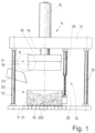
- a hydraulic cylinder 14 In the middle (relative to the base area) of the press yoke 12 there is a hydraulic cylinder 14.
- a cylinder body 15 of the hydraulic body 14 is firmly connected to the press yoke 12 above the same.
- the device also has a press basket 20 arranged below the press ram 17.
- the press basket 20 is completely open on its top and bottom, for which purpose it consists of a surrounding basket casing 21.
- the press basket 20 rests with its open bottom on the base plate 11.
- the base plate 11 is designed to be permeable to liquids, for example by means of a grid of through holes 22 in the base plate 11.
- Fig. 1 In the initial position of the device shown with the press ram 17 raised and the piston rod 16 of the hydraulic cylinder 14 retracted, there is a gap between the underside of the press membrane 19 and the open top of the press basket 20. This is used to load the press basket 20 with laundry to be drained and/or rinsed. The loading takes place by means of a Fig. 1 loading chute 23 shown.
- the press ram 17, namely both the ram plate 18 and the press membrane 19 thereof, are cylindrical. Accordingly, the press basket 20 is also cylindrical, namely in such a way that the press ram 17, in particular its press membrane 19, can dip into the press basket 20 through the open top of the latter and can thereby press or squeeze the laundry 10 and dewater and/or rinse it.
- the press membrane 19 is in vertical cross-section, of which the Fig. 2 and 3 show a part, hat-shaped.
- the press membrane 19 has a lower, circular membrane base 27 and a hose-like or cylinder-like membrane collar 28 adjoining the same above the membrane base 27.
- the underside of the membrane collar 28 is integrally formed on the membrane base 27, in such a way that the outside of the membrane collar 28 is flush with the outer edge of the membrane base 27.
- the membrane base 27 is provided with a circular base in the cylindrical press stamp 17 shown here.
- the membrane collar 28 is designed as a circumferential ring or tube with a free upper circular edge 29.
- An upper edge region 30 of the membrane collar 28 extends from the upper free edge 29 of the membrane collar 28 in the direction of the membrane base 27. This edge region 30 extends over approximately 20% to 60% of the height of the press membrane 19. In the embodiment shown in the figure, the height of the edge region 30 is approximately 40% to 50% of the total height of the press membrane 19.
- the upper edge 29 of the membrane collar 28 surrounds a circular upper opening 31 of the press membrane 19.
- the fastening ring 32 is dimensioned such that it can be inserted and/or inserted through the upper cylindrical opening 31 of the press membrane 19.
- a single ring-shaped projection 36 is assigned to the membrane collar 28 at a distance from the upper edge 29.
- the peripheral projection 36 is preferably placed inside the membrane collar 28 where the edge region 33 of the membrane collar 28 extending from the upper edge 29 ends.
- the distance of the peripheral ring-shaped projection 36 to the upper edge 29 of the membrane collar 28 is selected such that this distance corresponds to the height of the fastening ring 32 or is slightly larger ( Fig. 2 ).
- the projection 36 is wedge-shaped in that it tapers towards the inner end in the direction of the longitudinal center axis 33.
- An upper limit of the projection 36 which is wedge-shaped in cross-section, runs horizontally, whereas a lower limit is inclined.
- the horizontal limit of the projection 36 lies in a plane that is cut perpendicularly by the longitudinal center axis 33.
- the horizontal limit or wall of the circumferential projection 36 which is wedge-shaped in cross-section, forms a flat support surface 37 on which the underside of the fastening ring 32 rests, at least before it is connected to the stamp plate 18. or supports itself and thereby prevents the fastening ring 32 from falling into the press membrane 19.
- the circumferential projection 36 with its support surface 37 also limits the insertion depth of the fastening ring 32 in the press membrane 19.
- the fastening ring 32 is thus held by the circumferential projection 36 of the press membrane 19, in particular its membrane collar 28, preferably in the upper edge region 30 of the membrane collar 28.
- the circumferential projection 36 also serves to position and/or align the fastening ring 32 between the support surface 37 of the circumferential projection 36 and the upper edge 29 of the membrane collar 28.
- the plane intersecting the longitudinal center axis 33 at right angles, in which the support surface 37 of the circumferential projection 36 is located, runs parallel to the circumferential upper edge 29 of the membrane collar 28 and thus also parallel to the upper opening 31 of the press membrane 19.
- the circumferential projection 36 constricts an interior space 38 of the press membrane 19, which is surrounded by the membrane collar 28, to such an extent that it forms a sufficiently large support surface 37 for the underside of the fastening ring 32 inserted from above into the membrane collar 28.
- the cross section of the circumferential projection 36 is also formed such that the circumferential projection 36 has sufficient stability to support the fastening ring 32.
- An alternative embodiment of the press membrane 19 is conceivable in which, instead of a single circumferential projection 36 protruding into the interior 38 of the press membrane 19 and/or constricting it, several preferably identical projections are provided that are evenly distributed over the inner circumference of the membrane collar 28. These can be positioned in the same way and/or have the same cross-section such as the circumferential projection 36. In order for these several smaller projections to be able to bear the weight of the fastening ring 32, it is conceivable that these projections have a larger cross-section in terms of area, are enlarged in particular in the direction of the longitudinal center axis 33 and/or have a greater height.
- the circumferential projection 44 in the upper region of the membrane collar 28 constricts the opening 31 of the same to such an extent that the circumferential end of the projection 44 has a diameter which is slightly smaller than the outer diameter of the lower outer projection 39 of the fastening ring 32.
- the projection 44 constricts the interior 38 of the membrane collar 29 approximately as far as the projection 36 located at a distance below it for forming the support surface 37 for the fastening ring 32 ( Fig. 2 ).
- the constriction of the inner diameter of the membrane collar 28 by the upper projection 44 is less than that by the projection 36 for forming the support for the fastening ring 32.
- the fastening ring 32 is then lighter and can be inserted into the membrane collar 28 with a slight expansion of the upper end region of the latter.
- the stamp plate 18 is provided with a circumferential groove 45 which is open towards its underside.
- This circumferential groove 45 is located in the outer peripheral area of the stamp plate 18 ( Fig. 3 ), so that an outer ring wall 46 of the groove 45 is somewhat spaced from the outer circumferential surface 47 of the stamp plate 18.
- the stamp plate 18 then has an - albeit narrow - ring wall for the outer boundary of the groove 45.
- the groove 45 is further limited by an inner ring wall 48 and an annular wall to form a groove base 49.
- the annular groove base 49 lies in a plane which is cut perpendicularly by the longitudinal center axis 33 and runs parallel to the underside and/or the top of the stamp plate 18.
- the inner ring wall 48 of the groove 45 runs perpendicular to the groove base 49 and parallel to the longitudinal center axis 33.
- the outer ring wall 46 of the groove 45 runs slightly obliquely so that it has a frustoconical shape concentrically surrounding the longitudinal center axis 33, the inclination of the outer ring wall 46 being directed such that its distance from the cylindrical outer peripheral surface 47 of the stamp plate 18 increases slightly towards the groove base 49 ( Fig. 3 ).
- the circumferential groove 45 in the underside of the stamp plate 18, which is open at the bottom, has a depth that corresponds to the height of the fastening ring 32 or - as in the embodiment shown - is somewhat less and can alternatively be somewhat larger.
- the width of the groove 44 is dimensioned such that when the fastening ring 32 is completely mounted under the stamp plate 18 and screwed tight by the screws 34 under the stamp plate 18, both the fastening ring 32 and the largest part of the upper edge area 30 of the membrane collar 28 fill the groove 44 and preferably at least part of the edge area 30 of the membrane collar 28 is pre-stressed. is held firmly pressed in the groove 44.
- the inner upper projection 44 engages under the edge 29 of the membrane collar 28 in the outer groove 43 of the fastening ring 32 and preferably fills it completely ( Fig. 3 ). This results in a positive connection of the press membrane 19 with the stamp plate 18 by means of the fastening ring 32.
- an additional force-fit connection can be created between the press membrane 19, the stamp plate 18 and/or the fastening ring 32 ( Fig. 3 ).
- the hydraulic cylinder 14 then lowers the stamping plate 18 only far enough so that it does not yet touch the top of the fastening ring 32, but the screws 34 can already be initially screwed into the threaded hole 35 in the fastening ring 32 from the stamping plate 18.
Landscapes
- Engineering & Computer Science (AREA)
- Mechanical Engineering (AREA)
- Textile Engineering (AREA)
- Separation Using Semi-Permeable Membranes (AREA)
- Diaphragms And Bellows (AREA)
Claims (5)
- Dispositif pour l'essorage de linge (10) avec un poinçon de pressage (17) pouvant être déplacé vers le haut et vers le bas, qui présente une plaque de poinçon (18) et une membrane de pressage flexible (19) pouvant être fixée de manière amovible sous celle-ci avec une bague de fixation (32), la membrane de pressage (19) présentant un fond de membrane (27) et une collerette de membrane (28) formée sur celui-ci avec un bord supérieur périphérique (29), et la collerette de membrane (28) présentant sur son côté intérieur au moins une saillie (36) qui est configurée en tant qu'appui pour la bague de fixation (32) jusqu'à la liaison de celle-ci avec la plaque de poinçon (18), caractérisé en ce que la bague de fixation (32) peut être insérée par le haut à travers une ouverture (31) dans la collerette de membrane (28) jusqu'à une surface d'appui (37) de l'au moins une saillie (36).
- Dispositif selon la revendication 1, caractérisé en ce que l'au moins une saillie (36) forme au moins une surface d'appui (37) pour la bague de fixation (32) au moins jusqu'à la liaison de la bague de fixation (32) avec un côté inférieur et/ou une rainure (45) dans le côté inférieur de la plaque de poinçon (18).
- Dispositif selon la revendication 1 ou 2, caractérisé en ce que la bague de fixation (32) présente sur sa circonférence extérieure un profilage qui dispose notamment d'au moins une saillie périphérique (39) dans la zone d'extrémité inférieure et/ou d'un rétrécissement ou d'une rainure périphérique (43), et une zone de bord supérieure (30) de la collerette de membrane (28) présente, entre le bord supérieur (29) et la surface d'appui (37) de l'au moins une saillie (39), un profilage côté intérieur qui correspond de préférence au profilage côté extérieur de la bague de fixation (32).
- Dispositif selon la revendication 2, caractérisé en ce que la rainure périphérique (45), qui est configurée pour recevoir au moins une grande partie de la bague de fixation (32) et la zone de bord supérieure (30) de la collerette de membrane (28) de la membrane de pressage (19) qui lui est associée, part d'un côté inférieur de la plaque de poinçon (18).
- Dispositif selon l'une quelconque des revendications précédentes, caractérisé en ce que l'au moins une saillie (36) est agencée suffisamment en dessous du bord supérieur (29) de la collerette de membrane (28) pour que la surface d'appui (37) de chaque saillie (36) se trouve à distance en dessous du bord supérieur (29) de la collerette de membrane (28), cette distance correspondant de préférence au moins à la hauteur de la bague de fixation (32).
Priority Applications (2)
| Application Number | Priority Date | Filing Date | Title |
|---|---|---|---|
| DK23155754.7T DK4198187T3 (da) | 2020-01-21 | 2021-01-19 | Pressemembran til afvanding af vasketøj |
| EP23155754.7A EP4198187B1 (fr) | 2020-01-21 | 2021-01-19 | Membrane de compression pour la déshydratation du linge |
Applications Claiming Priority (1)
| Application Number | Priority Date | Filing Date | Title |
|---|---|---|---|
| DE202020000223.2U DE202020000223U1 (de) | 2020-01-21 | 2020-01-21 | Pressmenbran und eine solche aufweisende Vorrichtung zum Entwässern von Wäsche |
Related Child Applications (2)
| Application Number | Title | Priority Date | Filing Date |
|---|---|---|---|
| EP23155754.7A Division EP4198187B1 (fr) | 2020-01-21 | 2021-01-19 | Membrane de compression pour la déshydratation du linge |
| EP23155754.7A Division-Into EP4198187B1 (fr) | 2020-01-21 | 2021-01-19 | Membrane de compression pour la déshydratation du linge |
Publications (2)
| Publication Number | Publication Date |
|---|---|
| EP3854932A1 EP3854932A1 (fr) | 2021-07-28 |
| EP3854932B1 true EP3854932B1 (fr) | 2024-11-27 |
Family
ID=70546147
Family Applications (2)
| Application Number | Title | Priority Date | Filing Date |
|---|---|---|---|
| EP23155754.7A Active EP4198187B1 (fr) | 2020-01-21 | 2021-01-19 | Membrane de compression pour la déshydratation du linge |
| EP21152378.2A Active EP3854932B1 (fr) | 2020-01-21 | 2021-01-19 | Membrane à pression et dispositif comprenant une telle membrane à pression pour l'essorage du linge |
Family Applications Before (1)
| Application Number | Title | Priority Date | Filing Date |
|---|---|---|---|
| EP23155754.7A Active EP4198187B1 (fr) | 2020-01-21 | 2021-01-19 | Membrane de compression pour la déshydratation du linge |
Country Status (5)
| Country | Link |
|---|---|
| US (1) | US11661698B2 (fr) |
| EP (2) | EP4198187B1 (fr) |
| DE (1) | DE202020000223U1 (fr) |
| DK (2) | DK3854932T3 (fr) |
| ES (1) | ES3034931T3 (fr) |
Families Citing this family (1)
| Publication number | Priority date | Publication date | Assignee | Title |
|---|---|---|---|---|
| DE102022123549A1 (de) | 2022-09-14 | 2024-03-14 | MAXI-PRESS Elastomertechnik GmbH | Membrane für eine Entwässerungspresse und Verfahren zur Fertigung einer solchen Membrane |
Citations (1)
| Publication number | Priority date | Publication date | Assignee | Title |
|---|---|---|---|---|
| EP1388605A2 (fr) * | 2002-08-09 | 2004-02-11 | Herbert Kannegiesser GmbH | Presse à piston |
Family Cites Families (4)
| Publication number | Priority date | Publication date | Assignee | Title |
|---|---|---|---|---|
| DE8713472U1 (de) | 1987-10-07 | 1988-01-14 | Passat-Maschinenbau Gmbh, 7100 Heilbronn | Kolbenpresse zum Auspressen von Flüssigkeit aus einem Preßgut |
| CN102459743B (zh) * | 2009-06-10 | 2014-05-21 | 佩莱若林·米尔诺公司 | 洗熨物挤压设备和方法 |
| DE102014211460B4 (de) * | 2014-06-16 | 2023-02-16 | Contitech Vibration Control Gmbh | Presspolster für einen Pressstempel einer Wäschepresse mit aufquellbarem Dichtungselement |
| DE202019002021U1 (de) * | 2019-05-08 | 2019-07-29 | Herbert Kannegiesser Gmbh | Vorrichtung zum Entwässern von Wäsche |
-
2020
- 2020-01-21 DE DE202020000223.2U patent/DE202020000223U1/de active Active
-
2021
- 2021-01-19 DK DK21152378.2T patent/DK3854932T3/da active
- 2021-01-19 US US17/151,959 patent/US11661698B2/en active Active
- 2021-01-19 EP EP23155754.7A patent/EP4198187B1/fr active Active
- 2021-01-19 DK DK23155754.7T patent/DK4198187T3/da active
- 2021-01-19 ES ES23155754T patent/ES3034931T3/es active Active
- 2021-01-19 EP EP21152378.2A patent/EP3854932B1/fr active Active
Patent Citations (1)
| Publication number | Priority date | Publication date | Assignee | Title |
|---|---|---|---|---|
| EP1388605A2 (fr) * | 2002-08-09 | 2004-02-11 | Herbert Kannegiesser GmbH | Presse à piston |
Also Published As
| Publication number | Publication date |
|---|---|
| DE202020000223U1 (de) | 2020-04-20 |
| DK3854932T3 (da) | 2025-02-10 |
| ES3034931T3 (en) | 2025-08-26 |
| EP4198187A1 (fr) | 2023-06-21 |
| EP3854932A1 (fr) | 2021-07-28 |
| DK4198187T3 (da) | 2025-08-18 |
| EP4198187B1 (fr) | 2025-05-07 |
| DE202020000223U8 (de) | 2020-07-30 |
| US20210222349A1 (en) | 2021-07-22 |
| US11661698B2 (en) | 2023-05-30 |
Similar Documents
| Publication | Publication Date | Title |
|---|---|---|
| DE2442606C2 (de) | Verbindungskonstruktion für Gerüste | |
| EP0125456A2 (fr) | Plateau à membrane pour filtres-presses | |
| CH646636A5 (de) | Presse zum auspressen von fluessigkeitshaltigen stoffen. | |
| EP3854932B1 (fr) | Membrane à pression et dispositif comprenant une telle membrane à pression pour l'essorage du linge | |
| EP3736373B1 (fr) | Appareil pour expulser l'eau du linge | |
| DE2922888A1 (de) | Filterrohr fuer drainagezwecke | |
| DE2714963B2 (de) | Elastisches Rohrverbindungsstück | |
| WO2005083316A1 (fr) | Luminaire encastre dans le sol | |
| DE3811401C2 (fr) | ||
| DE3332773A1 (de) | Sanitaerarmatur | |
| DE1952446C3 (de) | Vorrichtung zum Befestigen einer Dacheindeckungsplatte an einem Tragglied | |
| EP1388605A2 (fr) | Presse à piston | |
| DE10347536B4 (de) | Verankerung eines Säulenschwenkkranes | |
| DE3141878C1 (de) | "Dichtungsring für Badewannenablaufventile" | |
| DE3440696C2 (fr) | ||
| DE10308576B4 (de) | Ringraumabdichtung | |
| EP0322588B1 (fr) | Joint | |
| DE102012215763A1 (de) | Baugruppe zum Verschließen einer Ablauföffnung eines Beckens | |
| DE8105934U1 (de) | Vorrichtung fuer tragarme von vorhangstangen | |
| CH461391A (de) | Dachwassereinlauf | |
| DE102005003395B3 (de) | Verwendung einer Blindnietmutter zur Herstellung eines Gebäudedaches | |
| DE3321115C2 (de) | Ringförmiges Umfasungselement für eine Unterdruck-Ziegelsteinformungsmaschine | |
| CH679539A5 (fr) | ||
| DE202022101408U1 (de) | Ablaufvorrichtung mit einem justierbaren Träger für eine Ablauf-Abdeckung | |
| DE202021100630U1 (de) | Montagegerechtes Pressengestell |
Legal Events
| Date | Code | Title | Description |
|---|---|---|---|
| PUAI | Public reference made under article 153(3) epc to a published international application that has entered the european phase |
Free format text: ORIGINAL CODE: 0009012 |
|
| STAA | Information on the status of an ep patent application or granted ep patent |
Free format text: STATUS: THE APPLICATION HAS BEEN PUBLISHED |
|
| AK | Designated contracting states |
Kind code of ref document: A1 Designated state(s): AL AT BE BG CH CY CZ DE DK EE ES FI FR GB GR HR HU IE IS IT LI LT LU LV MC MK MT NL NO PL PT RO RS SE SI SK SM TR |
|
| STAA | Information on the status of an ep patent application or granted ep patent |
Free format text: STATUS: REQUEST FOR EXAMINATION WAS MADE |
|
| 17P | Request for examination filed |
Effective date: 20220119 |
|
| RBV | Designated contracting states (corrected) |
Designated state(s): AL AT BE BG CH CY CZ DE DK EE ES FI FR GB GR HR HU IE IS IT LI LT LU LV MC MK MT NL NO PL PT RO RS SE SI SK SM TR |
|
| STAA | Information on the status of an ep patent application or granted ep patent |
Free format text: STATUS: EXAMINATION IS IN PROGRESS |
|
| 17Q | First examination report despatched |
Effective date: 20230623 |
|
| GRAP | Despatch of communication of intention to grant a patent |
Free format text: ORIGINAL CODE: EPIDOSNIGR1 |
|
| STAA | Information on the status of an ep patent application or granted ep patent |
Free format text: STATUS: GRANT OF PATENT IS INTENDED |
|
| INTG | Intention to grant announced |
Effective date: 20240719 |
|
| GRAS | Grant fee paid |
Free format text: ORIGINAL CODE: EPIDOSNIGR3 |
|
| GRAA | (expected) grant |
Free format text: ORIGINAL CODE: 0009210 |
|
| STAA | Information on the status of an ep patent application or granted ep patent |
Free format text: STATUS: THE PATENT HAS BEEN GRANTED |
|
| AK | Designated contracting states |
Kind code of ref document: B1 Designated state(s): AL AT BE BG CH CY CZ DE DK EE ES FI FR GB GR HR HU IE IS IT LI LT LU LV MC MK MT NL NO PL PT RO RS SE SI SK SM TR |
|
| REG | Reference to a national code |
Ref country code: GB Ref legal event code: FG4D Free format text: NOT ENGLISH |
|
| REG | Reference to a national code |
Ref country code: CH Ref legal event code: EP |
|
| REG | Reference to a national code |
Ref country code: DE Ref legal event code: R096 Ref document number: 502021005914 Country of ref document: DE |
|
| REG | Reference to a national code |
Ref country code: IE Ref legal event code: FG4D Free format text: LANGUAGE OF EP DOCUMENT: GERMAN |
|
| P01 | Opt-out of the competence of the unified patent court (upc) registered |
Free format text: CASE NUMBER: APP_63013/2024 Effective date: 20241127 |
|
| REG | Reference to a national code |
Ref country code: NL Ref legal event code: FP |
|
| REG | Reference to a national code |
Ref country code: DK Ref legal event code: T3 Effective date: 20250206 |
|
| REG | Reference to a national code |
Ref country code: LT Ref legal event code: MG9D |
|
| PG25 | Lapsed in a contracting state [announced via postgrant information from national office to epo] |
Ref country code: IS Free format text: LAPSE BECAUSE OF FAILURE TO SUBMIT A TRANSLATION OF THE DESCRIPTION OR TO PAY THE FEE WITHIN THE PRESCRIBED TIME-LIMIT Effective date: 20250327 Ref country code: HR Free format text: LAPSE BECAUSE OF FAILURE TO SUBMIT A TRANSLATION OF THE DESCRIPTION OR TO PAY THE FEE WITHIN THE PRESCRIBED TIME-LIMIT Effective date: 20241127 Ref country code: PT Free format text: LAPSE BECAUSE OF FAILURE TO SUBMIT A TRANSLATION OF THE DESCRIPTION OR TO PAY THE FEE WITHIN THE PRESCRIBED TIME-LIMIT Effective date: 20250327 |
|
| PG25 | Lapsed in a contracting state [announced via postgrant information from national office to epo] |
Ref country code: FI Free format text: LAPSE BECAUSE OF FAILURE TO SUBMIT A TRANSLATION OF THE DESCRIPTION OR TO PAY THE FEE WITHIN THE PRESCRIBED TIME-LIMIT Effective date: 20241127 |
|
| PG25 | Lapsed in a contracting state [announced via postgrant information from national office to epo] |
Ref country code: BG Free format text: LAPSE BECAUSE OF FAILURE TO SUBMIT A TRANSLATION OF THE DESCRIPTION OR TO PAY THE FEE WITHIN THE PRESCRIBED TIME-LIMIT Effective date: 20241127 |
|
| PG25 | Lapsed in a contracting state [announced via postgrant information from national office to epo] |
Ref country code: ES Free format text: LAPSE BECAUSE OF FAILURE TO SUBMIT A TRANSLATION OF THE DESCRIPTION OR TO PAY THE FEE WITHIN THE PRESCRIBED TIME-LIMIT Effective date: 20241127 |
|
| PG25 | Lapsed in a contracting state [announced via postgrant information from national office to epo] |
Ref country code: NO Free format text: LAPSE BECAUSE OF FAILURE TO SUBMIT A TRANSLATION OF THE DESCRIPTION OR TO PAY THE FEE WITHIN THE PRESCRIBED TIME-LIMIT Effective date: 20250227 |
|
| PG25 | Lapsed in a contracting state [announced via postgrant information from national office to epo] |
Ref country code: GR Free format text: LAPSE BECAUSE OF FAILURE TO SUBMIT A TRANSLATION OF THE DESCRIPTION OR TO PAY THE FEE WITHIN THE PRESCRIBED TIME-LIMIT Effective date: 20250228 Ref country code: LV Free format text: LAPSE BECAUSE OF FAILURE TO SUBMIT A TRANSLATION OF THE DESCRIPTION OR TO PAY THE FEE WITHIN THE PRESCRIBED TIME-LIMIT Effective date: 20241127 |
|
| PGFP | Annual fee paid to national office [announced via postgrant information from national office to epo] |
Ref country code: AT Payment date: 20250417 Year of fee payment: 5 |
|
| PG25 | Lapsed in a contracting state [announced via postgrant information from national office to epo] |
Ref country code: PL Free format text: LAPSE BECAUSE OF FAILURE TO SUBMIT A TRANSLATION OF THE DESCRIPTION OR TO PAY THE FEE WITHIN THE PRESCRIBED TIME-LIMIT Effective date: 20241127 |
|
| PG25 | Lapsed in a contracting state [announced via postgrant information from national office to epo] |
Ref country code: RS Free format text: LAPSE BECAUSE OF FAILURE TO SUBMIT A TRANSLATION OF THE DESCRIPTION OR TO PAY THE FEE WITHIN THE PRESCRIBED TIME-LIMIT Effective date: 20250227 |
|
| PG25 | Lapsed in a contracting state [announced via postgrant information from national office to epo] |
Ref country code: SM Free format text: LAPSE BECAUSE OF FAILURE TO SUBMIT A TRANSLATION OF THE DESCRIPTION OR TO PAY THE FEE WITHIN THE PRESCRIBED TIME-LIMIT Effective date: 20241127 |
|
| PG25 | Lapsed in a contracting state [announced via postgrant information from national office to epo] |
Ref country code: EE Free format text: LAPSE BECAUSE OF FAILURE TO SUBMIT A TRANSLATION OF THE DESCRIPTION OR TO PAY THE FEE WITHIN THE PRESCRIBED TIME-LIMIT Effective date: 20241127 |
|
| PG25 | Lapsed in a contracting state [announced via postgrant information from national office to epo] |
Ref country code: RO Free format text: LAPSE BECAUSE OF FAILURE TO SUBMIT A TRANSLATION OF THE DESCRIPTION OR TO PAY THE FEE WITHIN THE PRESCRIBED TIME-LIMIT Effective date: 20241127 |
|
| PG25 | Lapsed in a contracting state [announced via postgrant information from national office to epo] |
Ref country code: SK Free format text: LAPSE BECAUSE OF FAILURE TO SUBMIT A TRANSLATION OF THE DESCRIPTION OR TO PAY THE FEE WITHIN THE PRESCRIBED TIME-LIMIT Effective date: 20241127 |
|
| PG25 | Lapsed in a contracting state [announced via postgrant information from national office to epo] |
Ref country code: CZ Free format text: LAPSE BECAUSE OF FAILURE TO SUBMIT A TRANSLATION OF THE DESCRIPTION OR TO PAY THE FEE WITHIN THE PRESCRIBED TIME-LIMIT Effective date: 20241127 |
|
| PG25 | Lapsed in a contracting state [announced via postgrant information from national office to epo] |
Ref country code: IT Free format text: LAPSE BECAUSE OF FAILURE TO SUBMIT A TRANSLATION OF THE DESCRIPTION OR TO PAY THE FEE WITHIN THE PRESCRIBED TIME-LIMIT Effective date: 20241127 |
|
| REG | Reference to a national code |
Ref country code: DE Ref legal event code: R097 Ref document number: 502021005914 Country of ref document: DE |
|
| REG | Reference to a national code |
Ref country code: CH Ref legal event code: PL |
|
| PG25 | Lapsed in a contracting state [announced via postgrant information from national office to epo] |
Ref country code: SE Free format text: LAPSE BECAUSE OF FAILURE TO SUBMIT A TRANSLATION OF THE DESCRIPTION OR TO PAY THE FEE WITHIN THE PRESCRIBED TIME-LIMIT Effective date: 20241127 |
|
| PG25 | Lapsed in a contracting state [announced via postgrant information from national office to epo] |
Ref country code: MC Free format text: LAPSE BECAUSE OF FAILURE TO SUBMIT A TRANSLATION OF THE DESCRIPTION OR TO PAY THE FEE WITHIN THE PRESCRIBED TIME-LIMIT Effective date: 20241127 Ref country code: LU Free format text: LAPSE BECAUSE OF NON-PAYMENT OF DUE FEES Effective date: 20250119 |
|
| PLBE | No opposition filed within time limit |
Free format text: ORIGINAL CODE: 0009261 |
|
| STAA | Information on the status of an ep patent application or granted ep patent |
Free format text: STATUS: NO OPPOSITION FILED WITHIN TIME LIMIT |
|
| PG25 | Lapsed in a contracting state [announced via postgrant information from national office to epo] |
Ref country code: BE Free format text: LAPSE BECAUSE OF NON-PAYMENT OF DUE FEES Effective date: 20250131 |
|
| PG25 | Lapsed in a contracting state [announced via postgrant information from national office to epo] |
Ref country code: CH Free format text: LAPSE BECAUSE OF NON-PAYMENT OF DUE FEES Effective date: 20250131 |
|
| REG | Reference to a national code |
Ref country code: BE Ref legal event code: MM Effective date: 20250131 |
|
| 26N | No opposition filed |
Effective date: 20250828 |
|
| PG25 | Lapsed in a contracting state [announced via postgrant information from national office to epo] |
Ref country code: IE Free format text: LAPSE BECAUSE OF NON-PAYMENT OF DUE FEES Effective date: 20250119 |
|
| PGFP | Annual fee paid to national office [announced via postgrant information from national office to epo] |
Ref country code: NL Payment date: 20260121 Year of fee payment: 6 |
|
| PGFP | Annual fee paid to national office [announced via postgrant information from national office to epo] |
Ref country code: GB Payment date: 20260122 Year of fee payment: 6 |
|
| PGFP | Annual fee paid to national office [announced via postgrant information from national office to epo] |
Ref country code: DK Payment date: 20260121 Year of fee payment: 6 Ref country code: DE Payment date: 20260130 Year of fee payment: 6 |
|
| PGFP | Annual fee paid to national office [announced via postgrant information from national office to epo] |
Ref country code: FR Payment date: 20260123 Year of fee payment: 6 |