EP3855146B1 - Unité d'alimentation permettant de produire de l'énergie électrique, ustensile de cuisine ainsi que système de cuisine - Google Patents
Unité d'alimentation permettant de produire de l'énergie électrique, ustensile de cuisine ainsi que système de cuisine Download PDFInfo
- Publication number
- EP3855146B1 EP3855146B1 EP20152983.1A EP20152983A EP3855146B1 EP 3855146 B1 EP3855146 B1 EP 3855146B1 EP 20152983 A EP20152983 A EP 20152983A EP 3855146 B1 EP3855146 B1 EP 3855146B1
- Authority
- EP
- European Patent Office
- Prior art keywords
- supply unit
- temperature
- functional element
- kitchen
- electrical energy
- Prior art date
- Legal status (The legal status is an assumption and is not a legal conclusion. Google has not performed a legal analysis and makes no representation as to the accuracy of the status listed.)
- Active
Links
Images

Classifications
-
- A—HUMAN NECESSITIES
- A47—FURNITURE; DOMESTIC ARTICLES OR APPLIANCES; COFFEE MILLS; SPICE MILLS; SUCTION CLEANERS IN GENERAL
- A47J—KITCHEN EQUIPMENT; COFFEE MILLS; SPICE MILLS; APPARATUS FOR MAKING BEVERAGES
- A47J36/00—Parts, details or accessories of cooking-vessels
- A47J36/32—Time-controlled igniting mechanisms or alarm devices
- A47J36/321—Time-controlled igniting mechanisms or alarm devices the electronic control being performed over a network, e.g. by means of a handheld device
-
- G—PHYSICS
- G01—MEASURING; TESTING
- G01K—MEASURING TEMPERATURE; MEASURING QUANTITY OF HEAT; THERMALLY-SENSITIVE ELEMENTS NOT OTHERWISE PROVIDED FOR
- G01K13/00—Thermometers specially adapted for specific purposes
-
- A—HUMAN NECESSITIES
- A47—FURNITURE; DOMESTIC ARTICLES OR APPLIANCES; COFFEE MILLS; SPICE MILLS; SUCTION CLEANERS IN GENERAL
- A47J—KITCHEN EQUIPMENT; COFFEE MILLS; SPICE MILLS; APPARATUS FOR MAKING BEVERAGES
- A47J36/00—Parts, details or accessories of cooking-vessels
-
- A—HUMAN NECESSITIES
- A47—FURNITURE; DOMESTIC ARTICLES OR APPLIANCES; COFFEE MILLS; SPICE MILLS; SUCTION CLEANERS IN GENERAL
- A47J—KITCHEN EQUIPMENT; COFFEE MILLS; SPICE MILLS; APPARATUS FOR MAKING BEVERAGES
- A47J37/00—Baking; Roasting; Grilling; Frying
- A47J37/06—Roasters; Grills; Sandwich grills
- A47J37/0623—Small-size cooking ovens, i.e. defining an at least partially closed cooking cavity
- A47J37/0629—Small-size cooking ovens, i.e. defining an at least partially closed cooking cavity with electric heating elements
-
- A—HUMAN NECESSITIES
- A47—FURNITURE; DOMESTIC ARTICLES OR APPLIANCES; COFFEE MILLS; SPICE MILLS; SUCTION CLEANERS IN GENERAL
- A47J—KITCHEN EQUIPMENT; COFFEE MILLS; SPICE MILLS; APPARATUS FOR MAKING BEVERAGES
- A47J37/00—Baking; Roasting; Grilling; Frying
- A47J37/06—Roasters; Grills; Sandwich grills
- A47J37/0623—Small-size cooking ovens, i.e. defining an at least partially closed cooking cavity
- A47J37/0664—Accessories
-
- G—PHYSICS
- G01—MEASURING; TESTING
- G01K—MEASURING TEMPERATURE; MEASURING QUANTITY OF HEAT; THERMALLY-SENSITIVE ELEMENTS NOT OTHERWISE PROVIDED FOR
- G01K1/00—Details of thermometers not specially adapted for particular types of thermometer
- G01K1/02—Means for indicating or recording specially adapted for thermometers
- G01K1/024—Means for indicating or recording specially adapted for thermometers for remote indication
-
- H—ELECTRICITY
- H10—SEMICONDUCTOR DEVICES; ELECTRIC SOLID-STATE DEVICES NOT OTHERWISE PROVIDED FOR
- H10N—ELECTRIC SOLID-STATE DEVICES NOT OTHERWISE PROVIDED FOR
- H10N10/00—Thermoelectric devices comprising a junction of dissimilar materials, i.e. devices exhibiting Seebeck or Peltier effects
- H10N10/10—Thermoelectric devices comprising a junction of dissimilar materials, i.e. devices exhibiting Seebeck or Peltier effects operating with only the Peltier or Seebeck effects
-
- G—PHYSICS
- G01—MEASURING; TESTING
- G01K—MEASURING TEMPERATURE; MEASURING QUANTITY OF HEAT; THERMALLY-SENSITIVE ELEMENTS NOT OTHERWISE PROVIDED FOR
- G01K1/00—Details of thermometers not specially adapted for particular types of thermometer
- G01K1/16—Special arrangements for conducting heat from the object to the sensitive element
-
- G—PHYSICS
- G01—MEASURING; TESTING
- G01K—MEASURING TEMPERATURE; MEASURING QUANTITY OF HEAT; THERMALLY-SENSITIVE ELEMENTS NOT OTHERWISE PROVIDED FOR
- G01K2207/00—Application of thermometers in household appliances
- G01K2207/02—Application of thermometers in household appliances for measuring food temperature
- G01K2207/06—Application of thermometers in household appliances for measuring food temperature for preparation purposes
-
- G—PHYSICS
- G01—MEASURING; TESTING
- G01K—MEASURING TEMPERATURE; MEASURING QUANTITY OF HEAT; THERMALLY-SENSITIVE ELEMENTS NOT OTHERWISE PROVIDED FOR
- G01K2215/00—Details concerning sensor power supply
Definitions
- the invention relates to a supply unit for generating electrical energy, a kitchen utensil and a kitchen system.
- thermoelectric energy supply within the temperature zones is often not possible or difficult to implement if any energy storage devices, such as batteries, are protected from the effects of temperature. Furthermore, such temperature zones are often shielded from radio signals by a cover on the kitchen appliance, so that, for example, temperature values are usually checked using an analogue display that can be viewed through a viewing window, such as an oven window.
- a supply unit for generating electrical energy for a function during operation of a functional element of a kitchen utensil that can be arranged in a first temperature range.
- the supply unit has a first temperature section for arrangement in the first temperature range and a second temperature section for arrangement in a second temperature range.
- the second temperature range has the first temperature range a temperature difference.
- the supply unit has a supply means for providing electrical energy for the function during operation of the functional element.
- the supply means comprises a conversion element for converting thermal energy into electrical energy depending on the temperature difference.
- the supply unit can thus also be referred to as an energy supply unit or energy supply unit.
- the electrical function can include a function of the functional element itself, such as a measuring function, within the first temperature range.
- the electrical function can enable the operation of the functional element and, for example, include an energy supply to the functional element.
- the electrical function includes data processing of data from the functional element and/or communication between the functional element and a user or another electrical component.
- the kitchen utensil can be, for example, a sensor or a measuring instrument. Additionally or alternatively, the kitchen utensil can also have one or more other functions for preparing food.
- the first temperature range can include a heat zone or a cold zone.
- the supply unit can be arranged on an oven, a pot, a refrigerator or an electric food processor for the at least partially automated preparation of food in order to enable the electrical function when the functional element is operating.
- the first and second temperature sections of the supply unit can be connected to one another directly or indirectly.
- both temperature sections comprise a thermally conductive material, such as a metal, in order to be able to at least partially transmit different temperatures in the first and second temperature ranges to the conversion element.
- the conversion element is in particular arranged in such a way that it can be at least partially exposed to the temperature difference between the first and second temperature ranges. The temperature difference can be used by the conversion element to generate electrical energy and provide it for the function.
- the supply unit can be used for energy management of the kitchen utensil while the functional element is in the first temperature range. It is therefore not necessary to protect an energy storage device against the temperature conditions in the first temperature range. Furthermore, a connection between the first temperature range and the second temperature range can be established by the supply unit.
- the conversion element has an electrothermal converter.
- the electrothermal converter can be a semiconductor component, preferably a Peltier element.
- the electrothermal converter can also be referred to as a thermoelectric generator or thermoelectric converter.
- the electrical energy can preferably be generated by the electrothermal converter using the Seebeck effect.
- an electrical voltage and/or an electrical current can be induced in the conversion element.
- the electrical energy can be provided by the means for providing the electrical function when the functional element is operating.
- the conversion unit can be connected or connectable directly or indirectly to an electrical component.
- the first and second temperature sections are connected by a heat-conducting bridge element, in particular wherein the bridge element has an insulation layer for heat insulation from the environment.
- the bridge element can comprise a heat-conducting material in order to enable heat exchange between the first and second temperature sections.
- the insulation layer in particular comprises a weakly heat-conducting material.
- the insulation layer can comprise a plastic.
- the insulation layer can prevent a user who touches the supply unit from being exposed to a transmitted temperature of the first temperature range. Furthermore, this can reduce or prevent a temperature loss between the first and second temperature range. This can ensure the highest possible
- the bridge element can preferably have a flat extension and/or be curved in order to be able to be clamped into a flap of the kitchen appliance, such as an oven door, a refrigerator door or the like.
- the bridge element can comprise a sheet metal body.
- the supply unit can be attached to the kitchen appliance by the bridge element.
- the bridge element is designed for arrangement in a door area of a kitchen appliance, so that the first temperature range can be arranged in an interior of the kitchen appliance and the second temperature range in an exterior area, in particular wherein the bridge element and the first and second temperature sections form a U-shaped fastening section for fastening the supply unit to the kitchen appliance.
- the interior area can be, for example, a baking chamber of an oven, a cooking area of a pot or a container of a food processor or a cooling area of a refrigerator.
- the exterior area can preferably have an ambient temperature, in particular room temperature. This can create an advantageous temperature difference for generating electrical energy.
- the supply unit can thus make an actually inaccessible first temperature range of the kitchen appliance accessible for the electrical function even during operation.
- the supply unit can be hooked into a flap of the kitchen appliance thanks to the U-shaped fastening section. This can create a detachable fastening option that results from a geometric shape of the supply unit.
- the conversion element is arranged on the first temperature section, on the second temperature section and/or on the bridge element.
- the bridge element By arranging it on the bridge element, temperature from the first and second temperature ranges can be supplied to the conversion element from two sides of the conversion element.
- the conversion element By arranging it on the first or second temperature section, the conversion element can be exposed to the first or second temperature range itself and can be connected to the first or second temperature range via the first or second temperature range, the temperature of the other temperature range is supplied.
- An arrangement in the second temperature range and/or on the bridge element also has the advantage that the conversion element is not completely exposed to the first temperature range.
- the supply means has an additional energy source for providing electrical energy, preferably for the electrical function and/or another function, in particular wherein the supply means has a switching element for connecting the additional energy source for providing electrical energy.
- the additional energy source can have an energy store, e.g. in the form of a battery or an accumulator.
- the additional energy source has at least one photovoltaic module, at least one electroactive elastomer and/or at least one piezo element in order to generate the electrical energy.
- the additional energy source can support the conversion element in providing electrical energy.
- the conversion element can be switched off, in particular by the switching element, so that the electrical energy supply for the function for the kitchen utensil and/or another electrical function is provided entirely by the energy source.
- the switching element can comprise an electrical switch, in particular in the form of a relay or a semiconductor component.
- an electronic unit for data and/or signal processing is provided for the function of the kitchen utensil, in particular wherein a circuit board of the electronic unit is arranged at the second temperature section.
- the electronic unit can have at least one electronic component for data and/or signal processing.
- analog measurement signals of the functional element can be digitized by the electronic unit.
- the supply means can be designed to provide the electrical energy for the electronic unit.
- the data and/or signal processing can form the electrical function for which the electrical energy can be provided by the supply means.
- the arrangement of the circuit board at the second temperature section has the advantage that the circuit board is not the temperature in the first temperature range and can therefore be designed for operation at room temperature. Complex protective measures against a temperature in the first temperature range can therefore be omitted.
- the electronic unit has an evaluation module for evaluating measurement signals from the kitchen utensil, in particular the functional element.
- measurement data from the functional element can be evaluated or pre-evaluated by the electronic unit.
- the proximity of the electronic unit to the functional element can shorten a signal path so that transmission losses can be kept low.
- the supply unit can form a modular interface through the evaluation module, which can be coupled to different devices in order to transmit measurement data.
- the kitchen utensil, in particular the supply unit can have a display via which the processed measurement signals can be presented to a user.
- the evaluation module is arranged on the circuit board on the second temperature section in order to enable a temperature-protected arrangement of the evaluation unit.
- the evaluation unit can be connected to the supply means in order to be powered by the supply means.
- the supply means has a connecting means for a connection for power transmission to the functional element and/or for data communication with the functional element.
- the connection for power transmission can be a preferably detachable electrical connection.
- the connecting means can comprise electrical contacts, preferably with a plug or a socket for detachable coupling to the functional element.
- the connecting means comprises a cable which permanently electrically connects the functional element to the supply means.
- the connecting means can enable the functional element to be supplied in the first temperature range with the electrical energy provided by the supply means.
- data communication in particular wired data communication, can be enabled by the electrical connecting means.
- the electrical connection means have several connection contacts for separate power and signal transmission.
- the connecting means has an internal communication module for wireless data communication with the functional element of the kitchen utensil and/or that the electronic unit has an external communication module for wireless data communication with a terminal device.
- the internal communication module and/or the external communication module can each be understood to mean, for example, a WLAN module, a Bluetooth module, an NFC module and/or a mobile radio module. Due to the wireless connection, a cable connection of the supply unit to the terminal device and/or to the functional element may not be necessary.
- the terminal device can be understood to mean, for example, a user's mobile terminal device, such as a tablet or a smartphone, a food processor or another electronic device designed to receive data.
- the internal communication module of the connecting means is designed to transmit electrical energy via the wireless data connection.
- an RFID chip of the functional element can be powered by the wireless data connection.
- a cable connection in the first temperature range may not be necessary.
- the internal communication module and the external communication module can each enable data reception and/or data transmission.
- the internal communication module and the external communication module can also have coil antennas for data communication.
- the bridge element has a signal bridge for forwarding electrical signals between the first and second temperature ranges.
- the signal bridge can advantageously have an electrically conductive material in order to transport the electrical signals between the first and second temperature ranges.
- the signal bridge can be connected to the internal communication module and the external communication module for data communication.
- the signal bridge can comprise, for example, a cable or an electrically conductive sheet. It is also conceivable that the signal bridge extends in layers along the bridge element. The signal bridge can thus an advantageous possibility must be created to transport electrical signals into the first temperature range. For example, it is conceivable that the first temperature range is located in a Faraday cage which is shielded from electrical signals.
- the signal bridge can therefore overcome the shielding of the kitchen appliance.
- the communication signals can be transported optically through a viewing window of the kitchen appliance or at least partially by cable via an electrical power supply for lighting in the interior, such as oven lighting, in order to overcome the shielding.
- a kitchen utensil has a functional element for arrangement in a first temperature range and a supply unit according to the invention for generating electrical energy for a function during operation of the functional element.
- the supply unit comprises a first temperature section for arrangement in the first temperature range and a second temperature section for arrangement in a second temperature range which has a temperature difference to the first temperature range.
- the supply unit has a supply means for providing electrical energy for the function during operation of the functional element.
- the supply means comprises a conversion element for converting thermal energy into electrical energy depending on the temperature difference.
- a kitchen utensil brings with it the same advantages as have already been described in detail with reference to a supply unit according to the invention.
- the functional element and the supply unit can form a structural unit or can be combined in a modular manner.
- the functional element and the supply unit can be structurally separated and can be connected to a data communication connection, for example if the supply unit processes data from the functional element.
- the supply unit can preferably be connected to the functional element wirelessly or by cable or can be permanently connected.
- a connection to the first temperature range can be established through the kitchen utensil. without exposing critical components to the temperature in the first temperature range.
- the functional element has a sensor for recording process data when using the kitchen utensil and/or a kitchen appliance, in particular where the sensor is a temperature sensor.
- the functional element can thus be a measuring probe, for example.
- the sensor can be a thermistor for which electrical energy can be provided by the supply means.
- the kitchen utensil can be a meat thermometer.
- the process data can be, for example, cooking data for food that is prepared in the first temperature range.
- the process data is environmental data in the first temperature range.
- the process data can include temperature data and/or acoustic, optical and/or haptic data.
- noises or light spectra recorded by the functional element in the first temperature range can indicate wear on components of the kitchen appliance or kitchen utensil.
- the supply unit may comprise a sensor, in particular in the form of a temperature sensor.
- the functional element and a connecting means of the supply unit each have an internal communication module for connecting the functional element to the supply unit, in particular wirelessly, or that the connecting means has an electrical conductor for connecting the functional element to the supply unit.
- the electrical conductor can be a cable, for example. If the functional element itself has an internal communication module, a radio connection between the supply unit and the functional element can be made possible. The radio connection means that a cable connection to the functional element is not necessary.
- a kitchen system comprises a kitchen appliance with an interior space which has a temperature difference with respect to an exterior space.
- the kitchen system further comprises a Kitchen utensil according to the invention, which can be arranged partly indoors and partly outdoors.
- the kitchen appliance can be, for example, an oven, a pot, a refrigerator, a freezer compartment, a steamer or an electric food processor for the at least partially automated preparation of food.
- the interior can be a temperature zone that is colder or warmer than room temperature.
- the exterior can, for example, be at ambient temperature or room temperature.
- the interior of the kitchen appliance can be electrically shielded. Data communication between the exterior and interior can be enabled via the supply unit.
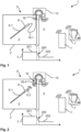
- FIG. 1 shows a kitchen system 1 according to the invention with a kitchen appliance 2 and a kitchen utensil 5 according to the invention.
- the kitchen appliance 2 can be an oven, for example.
- the kitchen utensil 5 has a functional element 6 for arrangement in a first temperature range 201 and a supply unit 10 for generating electrical energy.
- the supply unit 10 extends partly into an interior 3 and partly into an exterior 4 of the kitchen appliance 2.
- the first temperature range 201 is formed by the interior 3 and a second temperature range 202 is formed by the exterior 4.
- the first and second temperature ranges 201, 202 have a temperature difference 200 with respect to one another.
- the exterior 4 is at room temperature.
- the exterior 4 is in particular an environment of the kitchen appliance 2.
- the temperature T in the interior 3 is lower than in the exterior 4 if the kitchen appliance 2 is, for example, a refrigerator.
- the functional element 6 is arranged in the first temperature range 201 and has a sensor 6.1, in particular in the form of a temperature sensor.
- the functional element 6 can thus be, for example, a measuring sensor for measuring the temperature in the interior 3.
- the functional element 6 is electrically connected to the supply unit 10 via a connecting means 16, in particular in the form of a detachable electrical conductor 16.1 and a plug.
- the supply unit 10 is designed for wireless data communication with a user's terminal device 7.
- the terminal device 7 can be an electric food processor or a smartphone.
- the supply unit 10 can be designed for communication with different terminal devices 7.
- the wireless data communication can make sensor data from the sensor 6.1 of the functional element 6 available to a user.
- the supply unit 10 and the functional element 6 can each have an internal communication module 6.3, 18.4 for power transmission from the supply unit 10 to the functional element 6 and/or for data communication between the supply unit 10 and a functional element 6, as shown in Figure 2 shown.
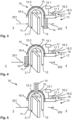
- the supply unit 10 is in Figure 3 shown in detail.
- the supply unit 10 has a first temperature section 11 for arrangement in the first temperature range 201 and a second temperature section 12 for arrangement in the second temperature range 202.
- the supply unit 10 is thus exposed to both temperature ranges 201, 202.
- the supply unit 10 also has a bridge element 15.
- the bridge element 15 and the first and second temperature sections 11, 12 form a U-shaped fastening section 15.2 for fastening the supply unit 10 to the kitchen appliance 2.
- the bridge element 15 preferably also has an insulation layer 15.1 for thermal insulation against the environment. This can reduce or prevent heat loss during heat transport between the first and second temperature sections 11, 12. Furthermore, this can protect a user from excessive heat.
- the supply unit 10 has a supply means 13.
- the supply means 13 comprises a conversion element 14 for converting thermal energy into electrical energy depending on the temperature difference 200 between the first and second temperature range 201, 202 or the first and second temperature section 11, 12.
- the conversion element 14 is an electrothermal converter, in particular in the form of a Peltier element. Heat is absorbed via the first temperature section 11 and conducted to the second temperature section 12 via the bridge element 15. As a result, the temperature difference 200 between the first and second temperature sections 11, 12 is created at least partially at the conversion element 14. Because the conversion element 14 is arranged at the second temperature section 12, the conversion element 14 is at least partially or completely exposed to the temperature difference 200.
- the resulting thermal energy can be converted by the conversion element 14 into electrical energy depending on the temperature difference 200.
- the conversion element 14 generates an electrical voltage and/or an electrical Current is induced in the supply means 13 and made available for the function.
- the function involves the processing and/or forwarding of radio signals for wireless communication of the functional element 6 in the first temperature range 201 and a user's terminal device 7.
- the functional element 6 can be supplied with power via the wireless communication in order to enable a measuring function or a feedback function, for example.
- the electrical energy is only provided for a function of the functional element 6, such as the measuring function.
- a permanent electrical connection is provided between the supply unit 10 and the functional element 6.
- the supply unit 10 has an electronic unit 18 for data and/or signal processing for the function of the kitchen utensil 5.
- the electronic unit 18 comprises a circuit board 18.1, on which an evaluation module 18.2 for evaluating measurement signals of the functional element 6 of the kitchen utensil 5 is arranged.
- the evaluation module 18.2 can be powered by the conversion element 14.
- the supply unit 10 has an external communication module 18.3 for wireless data communication with the terminal device 7 and an internal communication module 18.4 for wireless data communication with the functional element 6.
- the internal communication module 18.4 for wireless data communication with the functional element 6 is arranged at the first temperature section 11.
- the internal communication module 18.4 can be a coil antenna, in particular which is insensitive or less sensitive to the first temperature range 201.
- the circuit board 18.1 is arranged in particular at the second temperature section 12 and is therefore not directly exposed to the first temperature range 201.
- the circuit board 18.1 at the second temperature section 12 can be protected from heat conduction from the first temperature section 11 to the second temperature section 12 by the insulation layer 15.1.
- the bridge element 15 has a signal bridge 15.3. Electrical signals can be exchanged between the first and second temperature ranges 201, 202 via the signal bridge 15.3. For example, an electrical shielding of the interior 3 can be overcome via the signal bridge 15.3.
- the internal communication module 18.4 for wireless data communication with the functional element 6 can be connected to the circuit board 18.1 and/or the conversion element 14 via the signal bridge 15.3.
- the supply means 13 preferably has an additional energy source 17 for providing electrical energy.
- the additional energy source 17 can be, for example, a battery, an accumulator or the like.
- the supply means 13 also has an electrical switching element 17.1 for connecting the additional energy source 17. If, for example, the temperature difference 200 is not sufficient to generate the required electrical energy, the additional energy source 17 can be connected to the conversion element 14. However, it is also conceivable that the conversion element 14 is electrically separable in order to enable electrical energy to be provided entirely by the additional energy source 17.
- the conversion element 14 can be arranged according to Figure 4 be arranged at the first temperature section 11, so that a, preferably negative, heat conduction takes place from the second temperature section 12 via the bridge element 15 to the first temperature section 11.
- the temperature difference 200 at the first temperature section 11 can be tapped by the conversion element 14.
- the conversion element 14 can be arranged according to Figure 5 be arranged on the bridge element 15, so that a, in particular negative and/or positive, heat conduction from the first and second temperature sections 11, 12 to the bridge element 15 takes place and the temperature difference 200 is tapped by the conversion element 14 on the bridge element 15.
- FIG. 6 shows a kitchen utensil 5 with a supply unit 10 for generating electrical energy and a functional element 6, which form a structural unit.
- the kitchen utensil 5 is a meat thermometer.
- the supply unit 10 has a first temperature section 11, in which the functional element 6 is integrated.
- the first temperature section 11 has a needle-like shape in order to be inserted into a foodstuff together with the functional element 6 in order to record its internal temperature.
- a first temperature range 201 is present inside the foodstuff.
- the functional element 6 has a sensor 6.1 in the form of a temperature sensor.
- the supply unit 10 also has a provision means 13 for providing an electrical function for the kitchen utensil 5.
- the provision means 13 comprises a conversion element 14 in the form of an electrothermal converter.
- the supply unit 10 comprises a second temperature section 12, which can be arranged in a second temperature range 202, in which there is a temperature difference 200 to the first temperature range 201.
- the conversion element 14 is arranged in relation to the first and second temperature sections 11, 12, in particular between the first and second temperature sections 11, 12, in such a way that the conversion element 14 is exposed to the temperature difference 200.
- a bridge element 15 in the form of a thermally conductive section of the kitchen utensil 5 can be arranged between the first and second temperature sections 11, 12. Depending on the temperature difference 200, thermal energy can be converted into electrical energy by the conversion element 14.
- a connecting means 16 in the form of an electrical line from the conversion element 14 to the functional element 6 is provided. This allows the electrical energy to be made available to the functional element 6. Additionally or alternatively, the electrical energy of the conversion element 14 can be used to power, for example, a display 5.1, in particular a digital one, of the kitchen utensil 5 to display the temperature for a user.
Landscapes
- Engineering & Computer Science (AREA)
- Food Science & Technology (AREA)
- Physics & Mathematics (AREA)
- General Physics & Mathematics (AREA)
- Cookers (AREA)
- Control Of Resistance Heating (AREA)
Claims (15)
- Unité d'alimentation (10) pour générer de l'énergie électrique pour une fonction électrique lors d'un fonctionnement d'un élément fonctionnel (6) d'un ustensile de cuisine (5) pouvant être disposé dans une première zone de température (201), présentantune première section de température (11) destinée à être placée dans la première zone de température (201),une deuxième section de température (12) destinée à être disposée dans une deuxième zone de température (202) qui présente une différence de température (200) par rapport à la première zone de température (201), etun moyen de fourniture (13) pour fournir de l'énergie électrique pour la fonction lors du fonctionnement de l'élément fonctionnel (6), comprenant un élément de conversion (14) pour convertir l'énergie thermique en énergie électrique en fonction de la différence de température (200),dans lequel les première et deuxième sections de température (11, 12) sont reliées par un élément de pont thermiquement conducteur (15),caractérisé en ce quel'unité d'alimentation (10) peut être fixée par l'élément de pont (15) à un appareil de cuisine (2).
- Unité d'alimentation (10) selon la revendication 1,
caractérisé en ce que
l'élément de conversion (14) comporte un convertisseur électrothermique. - Unité d'alimentation (10) selon la revendication 1 ou 2,
caractérisé en ce que
l'élément de pont (15) présente une couche d'isolation (15.1) pour l'isolation thermique par rapport à un environnement. - Unité d'alimentation (10) selon l'une des revendications précédentes,
caractérisé en ce que
l'élément de pont (15) est conçu pour être disposé dans une zone de porte (3.1) de l'appareil de cuisine (2), de sorte que la première zone de température (201) peut être disposée dans un espace intérieur (3) de l'appareil de cuisine (2) et la deuxième zone de température (202) dans un espace extérieur (4), en particulier l'élément de pont (15) et les première et deuxième sections de température (11, 12) formant une section de fixation (15.2) en forme de U pour la fixation de l'unité d'alimentation (10) sur l'appareil de cuisine (2). - Unité d'alimentation (10) selon l'une des revendications précédentes,
caractérisé en ce que
l'élément de conversion (14) est disposé sur la première section de température (11, 12), sur la deuxième section de température (11, 12) et/ou sur l'élément de pont (15). - Unité d'alimentation (10) selon l'une des revendications précédentes,
caractérisé en ce que
le moyen de fourniture (13) présente une source d'énergie supplémentaire (17) pour la mise à disposition d'énergie électrique, en particulier le moyen de moyen de fourniture (13) présentant un élément de commutation (17.1) pour la mise en circuit de la source d'énergie supplémentaire (17) pour la mise à disposition d'énergie électrique. - Unité d'alimentation (10) selon l'une des revendications précédentes,
caractérisé en ce qu'
il est prévu une unité électronique (18) pour le traitement de données et/ou de signaux pour le fonctionnement de l'ustensile de cuisine (5), en particulier une carte imprimée (18.1) de l'unité électronique (18) étant disposée sur la deuxième section de température (12). - Unité d'alimentation (10) selon l'une des revendications précédentes,
caractérisé en ce que
l'unité électronique (18) présente un module d'évaluation (18.2) pour évaluer des signaux de mesure de l'ustensile de cuisine (5). - Unité d'alimentation (10) selon l'une des revendications précédentes,
caractérisé en ce que
le moyen de fourniture (13) présente un moyen de liaison (16) pour une liaison pour la transmission de courant à l'élément fonctionnel (6) et/ou pour la communication de données avec l'élément fonctionnel (6). - Unité d'alimentation (10) selon l'une des revendications précédentes,
caractérisé en ce que
le moyen de liaison (16) présente un module de communication intérieur (18.4) pour une communication de données sans fil avec l'élément fonctionnel (6) de l'ustensile de cuisine (5) et/ou en ce que l'unité électronique (18) présente un module de communication extérieur (18.3) pour une communication de données sans fil avec un terminal (7). - Unité d'alimentation (10) selon l'une des revendications précédentes,
caractérisé en ce que
l'élément de pont (15) présente un pont de signal (15.3) pour la transmission de signaux électriques entre la première et la deuxième zone de température (201, 202). - Ustensile de cuisine (5) présentantun élément fonctionnel (6) destiné à être placé dans une première zone de température (201), etune unité d'alimentation (10) selon l'une des revendications précédentes pour générer de l'énergie électrique pour une fonction électrique lors d'un fonctionnement de l'élément fonctionnel (6).
- Ustensile de cuisine (5) selon la revendication 12,
caractérisé en ce que
l'élément fonctionnel (6) présente un capteur (6.1) pour la saisie de données de processus lors de l'utilisation de l'ustensile de cuisine (5) et/ou de l'appareil de cuisine (2), en particulier dans lequel le capteur (6.1) est un capteur de température. - Ustensile de cuisine (5) selon la revendication 12 ou 13,
caractérisé en ce que
l'élément fonctionnel (6) et un moyen de liaison (16) de l'unité d'alimentation (10) présentent chacun un module de communication interne (6.3, 18.4) pour relier l'élément fonctionnel (6) à l'unité d'alimentation (10) ou que le moyen de liaison (16) présente un conducteur électrique (16.1) pour relier l'élément fonctionnel (6) à l'unité d'alimentation (10). - Système de cuisine (1) comprenantun appareil de cuisine (2) avec un espace intérieur (3) qui présente une différence de température (200) par rapport à un espace extérieur (4), etun ustensile de cuisine (5) selon l'une des revendications précédentes, qui peut être disposé en partie dans l'espace intérieur (3) et en partie dans l'espace extérieur (4).
Priority Applications (5)
| Application Number | Priority Date | Filing Date | Title |
|---|---|---|---|
| PL20152983.1T PL3855146T3 (pl) | 2020-01-21 | 2020-01-21 | Jednostka zasilająca do wytwarzania energii elektrycznej, przyrząd kuchenny i system kuchenny |
| ES20152983T ES3005845T3 (en) | 2020-01-21 | 2020-01-21 | Supply unit for generating electrical energy, kitchen utensil and kitchen system |
| EP20152983.1A EP3855146B1 (fr) | 2020-01-21 | 2020-01-21 | Unité d'alimentation permettant de produire de l'énergie électrique, ustensile de cuisine ainsi que système de cuisine |
| CN202110037417.5A CN113208447B (zh) | 2020-01-21 | 2021-01-12 | 用于产生电能的供电单元、厨房用具和厨房系统 |
| US17/153,109 US11747211B2 (en) | 2020-01-21 | 2021-01-20 | Supply unit for generating electric energy, kitchen utensil as well as kitchen system |
Applications Claiming Priority (1)
| Application Number | Priority Date | Filing Date | Title |
|---|---|---|---|
| EP20152983.1A EP3855146B1 (fr) | 2020-01-21 | 2020-01-21 | Unité d'alimentation permettant de produire de l'énergie électrique, ustensile de cuisine ainsi que système de cuisine |
Publications (3)
| Publication Number | Publication Date |
|---|---|
| EP3855146A1 EP3855146A1 (fr) | 2021-07-28 |
| EP3855146B1 true EP3855146B1 (fr) | 2024-11-06 |
| EP3855146C0 EP3855146C0 (fr) | 2024-11-06 |
Family
ID=69187576
Family Applications (1)
| Application Number | Title | Priority Date | Filing Date |
|---|---|---|---|
| EP20152983.1A Active EP3855146B1 (fr) | 2020-01-21 | 2020-01-21 | Unité d'alimentation permettant de produire de l'énergie électrique, ustensile de cuisine ainsi que système de cuisine |
Country Status (5)
| Country | Link |
|---|---|
| US (1) | US11747211B2 (fr) |
| EP (1) | EP3855146B1 (fr) |
| CN (1) | CN113208447B (fr) |
| ES (1) | ES3005845T3 (fr) |
| PL (1) | PL3855146T3 (fr) |
Families Citing this family (3)
| Publication number | Priority date | Publication date | Assignee | Title |
|---|---|---|---|---|
| CN114977888A (zh) * | 2021-04-23 | 2022-08-30 | 深圳市安服优智能互联科技有限公司 | 温差发电结构及测温传感器 |
| EP4119911B1 (fr) * | 2021-07-16 | 2024-05-29 | Vorwerk & Co. Interholding GmbH | Thermomètre alimentaire plongeant |
| USD1101580S1 (en) | 2024-01-31 | 2025-11-11 | Sharkninja Operating Llc | Temperature probe holder |
Family Cites Families (37)
| Publication number | Priority date | Publication date | Assignee | Title |
|---|---|---|---|---|
| US4727799A (en) * | 1985-07-01 | 1988-03-01 | Sharp Kabushiki Kaisha | Cooking appliance with sensor means |
| JP3316926B2 (ja) * | 1993-04-28 | 2002-08-19 | 松下電器産業株式会社 | 調理器具 |
| JPH0763343A (ja) * | 1993-08-24 | 1995-03-07 | Matsushita Electric Ind Co Ltd | 加熱調理器 |
| JP3712809B2 (ja) * | 1997-01-14 | 2005-11-02 | 新日本石油株式会社 | 熱併給発電装置 |
| FR2781931B1 (fr) * | 1998-07-31 | 2002-12-06 | Univ Lille Sciences Tech | Thermopiles a thermojonctions du type distribuees, fluxmetres thermiques radiatif et conductif mettant en oeuvre ces thermopiles, ainsi que leurs procedes de fabrication |
| JP2003322344A (ja) * | 2002-02-28 | 2003-11-14 | Mitsubishi Electric Corp | 加熱調理器 |
| JP4247460B2 (ja) * | 2002-03-15 | 2009-04-02 | 三菱電機株式会社 | システムキッチンの発電装置 |
| US20060016446A1 (en) * | 2004-07-24 | 2006-01-26 | Hu Caroline K | Gas stove with thermoelectric generator |
| ES2328769B1 (es) * | 2007-01-24 | 2010-08-30 | Pointjust, S.L. | Dispositivo y metodo para el control de la coccion de alimentos. |
| ITVA20070018U1 (it) * | 2007-03-22 | 2008-09-23 | Whirlpool Co | Dispositivo per la rilevazione della temperatura all'interno di un alimento posto in un forno |
| ATE541495T1 (de) * | 2009-03-02 | 2012-02-15 | Wei-Lun Peng | Flüssigkeitsbehälter mit fähigkeit zur eigenen herstellung von energie und temperaturanzeige |
| US8556502B2 (en) * | 2011-11-22 | 2013-10-15 | Electronic Controls Design, Inc. | Food temperature probe |
| CN202866324U (zh) * | 2012-08-03 | 2013-04-10 | 胡晓瑾 | 能源自给保温环保节能房屋 |
| KR101444806B1 (ko) * | 2012-08-23 | 2014-09-29 | 한국전기연구원 | 열전발전 겸용 가열용기 |
| US9341518B2 (en) * | 2013-08-27 | 2016-05-17 | Innovative Control Technologies, LLC | Method and apparatus for remotely monitoring liquid food products |
| US10524614B2 (en) * | 2014-10-07 | 2020-01-07 | Whirlpool Corporation | Powered cooking accessory for an oven cavity |
| ES2804535T3 (es) * | 2015-06-25 | 2021-02-08 | Apption Labs Ltd | Termómetro para alimentos |
| US10444080B2 (en) * | 2015-11-17 | 2019-10-15 | Haier Us Appliance Solutions, Inc. | Thermal management for a wireless cooking probe |
| US10416027B2 (en) * | 2015-11-17 | 2019-09-17 | Haier Us Appliance Solutions, Inc. | Thermal management for a wireless cooking probe |
| CN205560866U (zh) * | 2016-03-28 | 2016-09-07 | 宁波奥凯安全科技有限公司 | 一种家用燃气灶防干烧和熄火的安保装置 |
| DE102016206506A1 (de) * | 2016-04-18 | 2017-10-19 | Mahle International Gmbh | Thermoelektrisches Modul |
| CN107543615A (zh) * | 2016-06-24 | 2018-01-05 | 上海新微技术研发中心有限公司 | 温度传感器绝热封装结构 |
| CN107664534B (zh) * | 2016-07-27 | 2019-12-13 | 上海新微技术研发中心有限公司 | 温度传感器封装结构 |
| DE102017203493A1 (de) * | 2017-03-03 | 2018-09-06 | Mahle International Gmbh | Verfahren zum Herstellen eines thermoelektischen Moduls |
| US20180353003A1 (en) * | 2017-06-08 | 2018-12-13 | Ashok Sabata | Novel Sensor Probe to Monitor Temperature during Cooking |
| CN207050021U (zh) * | 2017-07-20 | 2018-02-27 | 南京航空航天大学 | 灶具自充电装置 |
| EP3446600B1 (fr) * | 2017-08-24 | 2020-08-12 | Eksen Makine Sanayi ve Ticaret A.S. | Procédé et dispositif de fabrication de boissons |
| CN207460034U (zh) * | 2017-10-19 | 2018-06-05 | 南京航空航天大学 | 灶具间歇式温差电堆发电装置 |
| CN108151085B (zh) * | 2018-03-22 | 2024-08-16 | 杭州老板电器股份有限公司 | 燃气灶文火控制系统及方法 |
| US20200101481A1 (en) * | 2018-09-27 | 2020-04-02 | Colorado School Of Mines | Thermoelectric irrigation module and methods of use thereof |
| KR102211397B1 (ko) * | 2019-04-19 | 2021-02-03 | 주식회사 한길엔씨티 | 면상발열체를 이용한 휴대용 조리기 |
| EP3994435A4 (fr) * | 2019-07-01 | 2022-08-24 | Thermasense Corp. | Appareil, systèmes et procédés d'interrogation thermique non invasive |
| WO2021138455A1 (fr) * | 2019-12-31 | 2021-07-08 | Traeger Pellet Grills, Llc | Dispositif de gril, composants de dispositif de gril et procédés associés |
| PL433545A1 (pl) * | 2020-04-15 | 2021-10-18 | Solgaz Spółka Z Ograniczoną Odpowiedzialnością | Pierścieniowy termoparowy układ pomiaru i regulacji temperatury |
| CN212204624U (zh) * | 2020-04-22 | 2020-12-22 | 珠海格力电器股份有限公司 | 厨房用具 |
| CN112038476B (zh) * | 2020-06-30 | 2023-01-06 | 中芯集成电路(宁波)有限公司上海分公司 | 热电堆传感器的制作方法 |
| DE102021110087A1 (de) * | 2021-04-21 | 2022-10-27 | Miele & Cie. Kg | Gargerät mit einer Branderkennungseinrichtung, Branderkennungssystem, Brandmeldeeinheit und Brandbekämpfungsverfahren |
-
2020
- 2020-01-21 ES ES20152983T patent/ES3005845T3/es active Active
- 2020-01-21 EP EP20152983.1A patent/EP3855146B1/fr active Active
- 2020-01-21 PL PL20152983.1T patent/PL3855146T3/pl unknown
-
2021
- 2021-01-12 CN CN202110037417.5A patent/CN113208447B/zh active Active
- 2021-01-20 US US17/153,109 patent/US11747211B2/en active Active
Also Published As
| Publication number | Publication date |
|---|---|
| CN113208447B (zh) | 2025-08-05 |
| US11747211B2 (en) | 2023-09-05 |
| PL3855146T3 (pl) | 2025-02-10 |
| US20210223111A1 (en) | 2021-07-22 |
| ES3005845T3 (en) | 2025-03-17 |
| EP3855146C0 (fr) | 2024-11-06 |
| EP3855146A1 (fr) | 2021-07-28 |
| CN113208447A (zh) | 2021-08-06 |
Similar Documents
| Publication | Publication Date | Title |
|---|---|---|
| EP3855146B1 (fr) | Unité d'alimentation permettant de produire de l'énergie électrique, ustensile de cuisine ainsi que système de cuisine | |
| DE102010055511B4 (de) | Elektronikmodul für eine temperaturüberwachte Zubereitung von Gargut in einem Kochgefäß | |
| US10883883B2 (en) | Wireless probe for food, and system and method for wireless food temperature real-time monitoring | |
| DE102018200886B3 (de) | Verfahren zum Überwachen eines elektrischen Stromflusses | |
| EP3286804A1 (fr) | Élément de connecteur enfichable comportant un moyen de surveillance de temperature | |
| EP3178136A1 (fr) | Connecteur enfichable comprenant un dispositif de capteur de température | |
| US11219333B2 (en) | Wireless temperature sensing system for a cooking appliance | |
| DE102020109480A1 (de) | Induktives Küchensystem | |
| EP1577653A1 (fr) | Système de surveillance à distance pour cuiseur à vapeur et des parties de cela | |
| EP4281736B1 (fr) | Sonde de température interne et système de surveillance de température | |
| DE102018124319A1 (de) | Verfahren und Vorrichtung zum Betreiben eines Kochfelds, Kochgeschirr und Kochfeld | |
| DE102018009749A1 (de) | Elektrisches Kontaktelement für einen Steckverbinder, Steckverbinder und Verfahren zum Überwachen eines elektrischen Stromflusses | |
| DE102022207991A1 (de) | Verfahren zum Betreiben eines kabellosen Gargutsensors, kabelloser Gargutsensor, Garvorrichtung und Garsystem | |
| DE102011085524B4 (de) | Gareinrichtung | |
| DE102014101156B4 (de) | Vorrichtung zum Bestimmen eines Messwerts in einer elektrischen Anlage und Verfahren | |
| DE202016105148U1 (de) | Küchengefäß mit integrierter Wiegevorrichtung | |
| DE4411850C2 (de) | Vorrichtung zur Erfassung von Temperaturen eines Gargefäßes | |
| DE102004004022B4 (de) | Kochfeld | |
| EP3517911B1 (fr) | Appareil de cuisson comprenant un adaptateur électrique | |
| DE102015212778A1 (de) | Abnehmbarer Kochsensor | |
| DE102023100519A1 (de) | Schnittstellenmodul für ein Induktionskochfeld eines Garsystems zum Garen von Gargut, Garsystem zum Garen von Gargut und Verfahren zum Betreiben eines Garsystems | |
| EP4467041A1 (fr) | Récipient de réception pour un appareil de cuisine, appareil de cuisine et procédé de fonctionnement d'un appareil de cuisine | |
| BE1032869B1 (de) | Gargeschirr | |
| DE102011086912B4 (de) | Gargeschirrvorrichtung und Systeme mit einer solchen Gargeschirrvorrichtung | |
| DE102024123867A1 (de) | Gargeschirr |
Legal Events
| Date | Code | Title | Description |
|---|---|---|---|
| PUAI | Public reference made under article 153(3) epc to a published international application that has entered the european phase |
Free format text: ORIGINAL CODE: 0009012 |
|
| STAA | Information on the status of an ep patent application or granted ep patent |
Free format text: STATUS: THE APPLICATION HAS BEEN PUBLISHED |
|
| AK | Designated contracting states |
Kind code of ref document: A1 Designated state(s): AL AT BE BG CH CY CZ DE DK EE ES FI FR GB GR HR HU IE IS IT LI LT LU LV MC MK MT NL NO PL PT RO RS SE SI SK SM TR |
|
| STAA | Information on the status of an ep patent application or granted ep patent |
Free format text: STATUS: REQUEST FOR EXAMINATION WAS MADE |
|
| 17P | Request for examination filed |
Effective date: 20211203 |
|
| RBV | Designated contracting states (corrected) |
Designated state(s): AL AT BE BG CH CY CZ DE DK EE ES FI FR GB GR HR HU IE IS IT LI LT LU LV MC MK MT NL NO PL PT RO RS SE SI SK SM TR |
|
| STAA | Information on the status of an ep patent application or granted ep patent |
Free format text: STATUS: EXAMINATION IS IN PROGRESS |
|
| 17Q | First examination report despatched |
Effective date: 20230627 |
|
| GRAP | Despatch of communication of intention to grant a patent |
Free format text: ORIGINAL CODE: EPIDOSNIGR1 |
|
| STAA | Information on the status of an ep patent application or granted ep patent |
Free format text: STATUS: GRANT OF PATENT IS INTENDED |
|
| RIC1 | Information provided on ipc code assigned before grant |
Ipc: G01K 1/024 20210101ALI20240523BHEP Ipc: G01K 13/00 20210101AFI20240523BHEP |
|
| INTG | Intention to grant announced |
Effective date: 20240612 |
|
| GRAS | Grant fee paid |
Free format text: ORIGINAL CODE: EPIDOSNIGR3 |
|
| GRAA | (expected) grant |
Free format text: ORIGINAL CODE: 0009210 |
|
| STAA | Information on the status of an ep patent application or granted ep patent |
Free format text: STATUS: THE PATENT HAS BEEN GRANTED |
|
| AK | Designated contracting states |
Kind code of ref document: B1 Designated state(s): AL AT BE BG CH CY CZ DE DK EE ES FI FR GB GR HR HU IE IS IT LI LT LU LV MC MK MT NL NO PL PT RO RS SE SI SK SM TR |
|
| REG | Reference to a national code |
Ref country code: GB Ref legal event code: FG4D Free format text: NOT ENGLISH |
|
| REG | Reference to a national code |
Ref country code: CH Ref legal event code: EP |
|
| REG | Reference to a national code |
Ref country code: DE Ref legal event code: R096 Ref document number: 502020009657 Country of ref document: DE |
|
| REG | Reference to a national code |
Ref country code: IE Ref legal event code: FG4D Free format text: LANGUAGE OF EP DOCUMENT: GERMAN |
|
| U01 | Request for unitary effect filed |
Effective date: 20241203 |
|
| U07 | Unitary effect registered |
Designated state(s): AT BE BG DE DK EE FI FR IT LT LU LV MT NL PT RO SE SI Effective date: 20241212 |
|
| REG | Reference to a national code |
Ref country code: ES Ref legal event code: FG2A Ref document number: 3005845 Country of ref document: ES Kind code of ref document: T3 Effective date: 20250317 |
|
| U20 | Renewal fee for the european patent with unitary effect paid |
Year of fee payment: 6 Effective date: 20250220 |
|
| PG25 | Lapsed in a contracting state [announced via postgrant information from national office to epo] |
Ref country code: IS Free format text: LAPSE BECAUSE OF FAILURE TO SUBMIT A TRANSLATION OF THE DESCRIPTION OR TO PAY THE FEE WITHIN THE PRESCRIBED TIME-LIMIT Effective date: 20250306 Ref country code: HR Free format text: LAPSE BECAUSE OF FAILURE TO SUBMIT A TRANSLATION OF THE DESCRIPTION OR TO PAY THE FEE WITHIN THE PRESCRIBED TIME-LIMIT Effective date: 20241106 |
|
| PG25 | Lapsed in a contracting state [announced via postgrant information from national office to epo] |
Ref country code: NO Free format text: LAPSE BECAUSE OF FAILURE TO SUBMIT A TRANSLATION OF THE DESCRIPTION OR TO PAY THE FEE WITHIN THE PRESCRIBED TIME-LIMIT Effective date: 20250206 |
|
| PG25 | Lapsed in a contracting state [announced via postgrant information from national office to epo] |
Ref country code: GR Free format text: LAPSE BECAUSE OF FAILURE TO SUBMIT A TRANSLATION OF THE DESCRIPTION OR TO PAY THE FEE WITHIN THE PRESCRIBED TIME-LIMIT Effective date: 20250207 |
|
| PG25 | Lapsed in a contracting state [announced via postgrant information from national office to epo] |
Ref country code: RS Free format text: LAPSE BECAUSE OF FAILURE TO SUBMIT A TRANSLATION OF THE DESCRIPTION OR TO PAY THE FEE WITHIN THE PRESCRIBED TIME-LIMIT Effective date: 20250206 |
|
| PG25 | Lapsed in a contracting state [announced via postgrant information from national office to epo] |
Ref country code: SM Free format text: LAPSE BECAUSE OF FAILURE TO SUBMIT A TRANSLATION OF THE DESCRIPTION OR TO PAY THE FEE WITHIN THE PRESCRIBED TIME-LIMIT Effective date: 20241106 |
|
| PG25 | Lapsed in a contracting state [announced via postgrant information from national office to epo] |
Ref country code: SK Free format text: LAPSE BECAUSE OF FAILURE TO SUBMIT A TRANSLATION OF THE DESCRIPTION OR TO PAY THE FEE WITHIN THE PRESCRIBED TIME-LIMIT Effective date: 20241106 |
|
| PG25 | Lapsed in a contracting state [announced via postgrant information from national office to epo] |
Ref country code: CZ Free format text: LAPSE BECAUSE OF FAILURE TO SUBMIT A TRANSLATION OF THE DESCRIPTION OR TO PAY THE FEE WITHIN THE PRESCRIBED TIME-LIMIT Effective date: 20241106 |
|
| PLBE | No opposition filed within time limit |
Free format text: ORIGINAL CODE: 0009261 |
|
| STAA | Information on the status of an ep patent application or granted ep patent |
Free format text: STATUS: NO OPPOSITION FILED WITHIN TIME LIMIT |
|
| PG25 | Lapsed in a contracting state [announced via postgrant information from national office to epo] |
Ref country code: MC Free format text: LAPSE BECAUSE OF FAILURE TO SUBMIT A TRANSLATION OF THE DESCRIPTION OR TO PAY THE FEE WITHIN THE PRESCRIBED TIME-LIMIT Effective date: 20241106 |
|
| 26N | No opposition filed |
Effective date: 20250807 |
|
| PG25 | Lapsed in a contracting state [announced via postgrant information from national office to epo] |
Ref country code: IE Free format text: LAPSE BECAUSE OF NON-PAYMENT OF DUE FEES Effective date: 20250121 |
|
| REG | Reference to a national code |
Ref country code: CH Ref legal event code: U11 Free format text: ST27 STATUS EVENT CODE: U-0-0-U10-U11 (AS PROVIDED BY THE NATIONAL OFFICE) Effective date: 20260201 |
|
| U20 | Renewal fee for the european patent with unitary effect paid |
Year of fee payment: 7 Effective date: 20260128 |
|
| PGFP | Annual fee paid to national office [announced via postgrant information from national office to epo] |
Ref country code: GB Payment date: 20260122 Year of fee payment: 7 |
|
| PGFP | Annual fee paid to national office [announced via postgrant information from national office to epo] |
Ref country code: ES Payment date: 20260217 Year of fee payment: 7 |
|
| PGFP | Annual fee paid to national office [announced via postgrant information from national office to epo] |
Ref country code: CH Payment date: 20260201 Year of fee payment: 7 |
|
| PGFP | Annual fee paid to national office [announced via postgrant information from national office to epo] |
Ref country code: PL Payment date: 20260108 Year of fee payment: 7 |