EP4119911B1 - Thermomètre alimentaire plongeant - Google Patents
Thermomètre alimentaire plongeant Download PDFInfo
- Publication number
- EP4119911B1 EP4119911B1 EP21186000.2A EP21186000A EP4119911B1 EP 4119911 B1 EP4119911 B1 EP 4119911B1 EP 21186000 A EP21186000 A EP 21186000A EP 4119911 B1 EP4119911 B1 EP 4119911B1
- Authority
- EP
- European Patent Office
- Prior art keywords
- food thermometer
- food
- heat conductor
- thermometer
- energy converter
- Prior art date
- Legal status (The legal status is an assumption and is not a legal conclusion. Google has not performed a legal analysis and makes no representation as to the accuracy of the status listed.)
- Active
Links
Images


Classifications
-
- G—PHYSICS
- G01—MEASURING; TESTING
- G01K—MEASURING TEMPERATURE; MEASURING QUANTITY OF HEAT; THERMALLY-SENSITIVE ELEMENTS NOT OTHERWISE PROVIDED FOR
- G01K7/00—Measuring temperature based on the use of electric or magnetic elements directly sensitive to heat ; Power supply therefor, e.g. using thermoelectric elements
- G01K7/02—Measuring temperature based on the use of electric or magnetic elements directly sensitive to heat ; Power supply therefor, e.g. using thermoelectric elements using thermoelectric elements, e.g. thermocouples
- G01K7/04—Measuring temperature based on the use of electric or magnetic elements directly sensitive to heat ; Power supply therefor, e.g. using thermoelectric elements using thermoelectric elements, e.g. thermocouples the object to be measured not forming one of the thermoelectric materials
-
- G—PHYSICS
- G01—MEASURING; TESTING
- G01K—MEASURING TEMPERATURE; MEASURING QUANTITY OF HEAT; THERMALLY-SENSITIVE ELEMENTS NOT OTHERWISE PROVIDED FOR
- G01K1/00—Details of thermometers not specially adapted for particular types of thermometer
- G01K1/16—Special arrangements for conducting heat from the object to the sensitive element
-
- G—PHYSICS
- G01—MEASURING; TESTING
- G01K—MEASURING TEMPERATURE; MEASURING QUANTITY OF HEAT; THERMALLY-SENSITIVE ELEMENTS NOT OTHERWISE PROVIDED FOR
- G01K7/00—Measuring temperature based on the use of electric or magnetic elements directly sensitive to heat ; Power supply therefor, e.g. using thermoelectric elements
- G01K7/16—Measuring temperature based on the use of electric or magnetic elements directly sensitive to heat ; Power supply therefor, e.g. using thermoelectric elements using resistive elements
-
- G—PHYSICS
- G01—MEASURING; TESTING
- G01K—MEASURING TEMPERATURE; MEASURING QUANTITY OF HEAT; THERMALLY-SENSITIVE ELEMENTS NOT OTHERWISE PROVIDED FOR
- G01K1/00—Details of thermometers not specially adapted for particular types of thermometer
-
- G—PHYSICS
- G01—MEASURING; TESTING
- G01K—MEASURING TEMPERATURE; MEASURING QUANTITY OF HEAT; THERMALLY-SENSITIVE ELEMENTS NOT OTHERWISE PROVIDED FOR
- G01K1/00—Details of thermometers not specially adapted for particular types of thermometer
- G01K1/02—Means for indicating or recording specially adapted for thermometers
- G01K1/024—Means for indicating or recording specially adapted for thermometers for remote indication
-
- G—PHYSICS
- G01—MEASURING; TESTING
- G01K—MEASURING TEMPERATURE; MEASURING QUANTITY OF HEAT; THERMALLY-SENSITIVE ELEMENTS NOT OTHERWISE PROVIDED FOR
- G01K13/00—Thermometers specially adapted for specific purposes
- G01K13/10—Thermometers specially adapted for specific purposes for measuring temperature within piled or stacked materials
-
- H—ELECTRICITY
- H02—GENERATION; CONVERSION OR DISTRIBUTION OF ELECTRIC POWER
- H02N—ELECTRIC MACHINES NOT OTHERWISE PROVIDED FOR
- H02N11/00—Generators or motors not provided for elsewhere; Alleged perpetua mobilia obtained by electric or magnetic means
- H02N11/002—Generators
-
- G—PHYSICS
- G01—MEASURING; TESTING
- G01K—MEASURING TEMPERATURE; MEASURING QUANTITY OF HEAT; THERMALLY-SENSITIVE ELEMENTS NOT OTHERWISE PROVIDED FOR
- G01K2207/00—Application of thermometers in household appliances
- G01K2207/02—Application of thermometers in household appliances for measuring food temperature
- G01K2207/06—Application of thermometers in household appliances for measuring food temperature for preparation purposes
-
- H—ELECTRICITY
- H02—GENERATION; CONVERSION OR DISTRIBUTION OF ELECTRIC POWER
- H02J—ELECTRIC POWER NETWORKS; CIRCUIT ARRANGEMENTS OR SYSTEMS FOR SUPPLYING OR DISTRIBUTING ELECTRIC POWER; SYSTEMS FOR STORING ELECTRIC ENERGY
- H02J50/00—Circuit arrangements or systems for wireless supply or distribution of electric power
- H02J50/001—Energy harvesting or scavenging
Definitions
- a food thermometer is a temperature measuring device that is designed and suitable for measuring temperatures in a food during its preparation.
- a food thermometer can therefore measure temperatures that can occur during the preparation of a meal. Temperatures that deviate significantly from this cannot be measured.
- a food thermometer can also withstand the environmental conditions that can occur during the preparation of a meal.
- a food thermometer in the sense of the present invention is not designed to measure very low temperatures, such as temperatures well below minus temperatures, such as those reached in standard household freezers or freezer cabinets.
- a food thermometer in the sense of the present invention is therefore not designed to measure temperatures of less than -70°C.
- a food thermometer in the sense of the present invention is designed so that it can no longer measure temperatures below -50°C, because food is usually prepared using heat and very low temperatures are only used for freezing food.
- a food thermometer in the sense of the present invention can withstand a steam atmosphere.
- a food thermometer is therefore generally encapsulated in a watertight manner.
- a food thermometer in the sense of the present invention is resistant to common ingredients in a dish, such as acid from lemons or vinegar.
- a food thermometer is a piercing food thermometer in the sense of the present invention if it is intended and suitable for being inserted into food in order to be able to measure a temperature inside the food.
- a piercing food thermometer has an elongated measuring probe with a pointed or at least a very thin end in order to be able to insert the measuring probe into relatively solid food such as meat.
- the measuring probe comprises a sensor with which a temperature can be measured.
- a piercing food thermometer has a handle part that is not intended to be inserted into the food.
- the handle part can be grasped by a user in order to be able to pull the piercing food thermometer out of a food or dish.
- the handle part can also comprise a sensor with which a temperature can be measured. The temperature outside of a food or dish can then also be measured.
- a piercing food thermometer within the meaning of the present invention is an electric piercing food thermometer if it requires electrical power to operate.
- An electric piercing food thermometer can therefore comprise a battery or can be connected to an external electrical energy source in order to be supplied with electrical power.
- Printed matter EN 10 2007 018 245 A1 discloses a temperature probe for an oven, in which electrical energy for the operation of transmitting means is generated by means of a temperature difference between two parallel disks.
- Publication US 2018 / 0 353 003 A1 describes a system for monitoring food temperature in a high temperature environment, which includes a dual thermocouple for simultaneously measuring air temperature and food temperature.
- Publication EN 10 2010 020 778 A1 discloses an autonomous temperature transmitter for use in process engineering plants, which partially extends into a process vessel.
- Publication EP 1 624 724 A1 describes a sensor and a system for detecting a parameter during thermal treatment of a food product.
- the object of the present invention is to be able to measure the temperature in a dish during preparation independently of an external power supply.
- thermometer having the features of the first claim serves.
- Advantageous embodiments emerge from the dependent claims.
- the electric penetration food thermometer provided to solve the problem comprises an elongated measuring probe. There is a temperature sensor inside the measuring probe.
- the measuring probe is the part of the food thermometer that is designed and suitable for being inserted into a food in order to be able to measure a temperature inside the food.
- the measuring sensor is elongated if it is much longer than it is wide and deep, or if the diameter is much smaller than the length of the measuring sensor.
- the measuring sensor can be circular in cross-section. However, the measuring sensor can be oval, square or polygonal in cross-section, for example.
- the measuring sensor is generally straight so that it can be easily inserted into a food item and easily pulled out again.
- the measuring sensor can be cylindrical.
- the measuring sensor can be at least 3, 4 or 5 cm long, for example.
- the measuring sensor can be no more than 12, 10 or 8 cm long, for example.
- the measuring sensor can be a maximum of 2 cm or 1 cm wide and/or deep, or the diameter can be a maximum of 2 cm or 1 cm.
- the housing of the measuring sensor has a large surface area and is basically thin-walled, it can be made of a metal that is not optimized in terms of heat-conducting properties.
- the housing of the measuring sensor can therefore be partially or completely made of stainless steel. However, it can also be partially or completely made of aluminum.
- a handle part of the food thermometer is not part of the measuring sensor.
- a handle part is intended and suitable to be grasped in order to insert the measuring sensor into a food and to pull the measuring sensor out of the food or the dish made from it.
- a handle part therefore usually comprises a cover or casing made of a thermally insulating material such as plastic.
- a temperature sensor is an electrical or electronic component that supplies an electrical signal as a measure of the temperature.
- the temperature sensor can, for example, comprise an electrical conductor whose temperature-dependent electrical resistance is measured. The measured electrical resistance is then the measure of the temperature.
- the energy converter that converts a temperature difference into an electrical current.
- thermometer If a food thermometer is inserted into a food and the food is then heated in an oven, for example, the sensor remains comparatively cool compared to the temperature outside the food.
- the food thermometer uses this temperature difference with the help of the heat conductor and the energy converter to generate an electrical current.
- the electrical current generated in this way can then be used to charge a battery in the food thermometer and/or to supply electrical current to the control electronics of the food thermometer.
- the heat conductor preferably extends from the energy converter to a free end of the food thermometer in order to optimise power generation. If, for example, the measuring sensor is directly connected to a handle part and the energy converter is located in the measuring sensor, then the heat conductor preferably leads through the handle part and at least through a sleeve or casing of the handle part which consists of a thermally insulating material. The heat conductor can then form the end of the handle part. This end of the handle part is basically a blunt end. If, for example, the measuring sensor is directly connected to a handle part and the energy converter is located in the handle part, then the heat conductor preferably leads through the entire measuring sensor until the heat conductor has reached the corresponding end of the measuring sensor. This end of the food thermometer is basically a pointed end.
- the heat conductor is preferably completely or at least predominantly rod-shaped in order to be able to extend suitably far within the housing of the food thermometer.
- the heat conductor can, for example, extend from a rear third of the food thermometer to a front third of the food thermometer in order to be able to transport heat suitably for the purpose of generating electricity.
- the energy converter is then arranged in one of the two thirds.
- the length of the heat conductor is preferably at least half as long, preferably at least 2/3 as long as the length of the food thermometer in order to be able to transport heat appropriately for power generation.
- the heat conductor is not only used to conduct heat, in order to keep the installation space small.
- the food thermometer can therefore comprise a radio device and the heat conductor can be an antenna of the radio device.
- the radio device can then transmit measured temperatures wirelessly to an external receiving device.
- the heat conductor can be an electrical conductor through which generated current can flow to a battery and/or to an electrical consumer of the food thermometer.
- the heat conductor can serve as a holder for other components of the food thermometer.
- One or more other components, such as an electrical conductor are then attached to the heat conductor.
- This electrical conductor can, for example, connect a temperature sensor to control electronics.
- An energy converter is a circuit with two different electrical conductors for generating electrical current using the Seebeck effect.
- the Seebeck effect refers to the creation of a voltage in a circuit with two different conductors when there is a temperature difference at the contact points.
- the heat conductor can be adjacent to a contact point in order to bring it to a different temperature than the other contact point during operation.
- the energy converter is a hollow cylinder. This makes it easier to achieve different temperatures at contact points. The efficiency of power generation can thus be increased. This is especially true if the measuring sensor is also cylindrical. The hollow cylinder can then be directly adjacent to the housing of the measuring sensor so that the contact points adjacent to it are optimally tempered. If the measuring sensor is only approximately cylindrical, it is advantageous if the energy converter also has a corresponding shape. The energy converter is then also only approximately cylindrical.
- the heat conductor leads into the hollow cylinder in order to be able to control the temperature in an optimized manner.
- the efficiency of the electrical power generation can thus be improved.
- the heat conductor is adjacent to one of the two contact points in order to optimize the desired temperature control.
- the heat conductor can then only be separated from one contact point of the energy converter by an electrical insulator.
- the heat conductor is then directly adjacent to one side of the electrical insulator and thus makes contact with it.
- the contact point is then directly adjacent to the other side of the electrical insulator.
- the electrical insulator can, for example, consist of a ceramic material that conducts heat well.
- a thermal insulator can be placed adjacent to the heat conductor within the sensor. This ensures that the heat conductor is not cooled during the preparation of food with a thermometer inserted into it. The efficiency of electrical power generation can thus be further improved.
- the other contact point of the energy converter can be thermally connected to the housing of the temperature sensor via another heat conductor, for example made of copper, if the energy converter is located in the sensor.
- the other heat conductor can in turn be separated from the other contact point by an electrical insulator.
- the other contact point can also be directly adjacent to the housing of the sensor in order to be temperature-controlled in a particularly suitable way.
- An electrical insulator can then be located between the other contact point and the housing of the sensor. This can again improve the efficiency of generating electrical current.
- the other heat conductor can be connected to a housing part of the handle part. The other heat conductor can therefore contact the part of the housing in which the heat conductor is located in order to improve the generation of electrical current.
- the provision of one or two heat conductors is not absolutely necessary in order to generate electricity.
- the energy converter cannot be dimensioned and arranged according to the invention in such a way that one contact point is in the area of the food thermometer that is kept relatively cool during the preparation of a meal and the other contact point is in the area of the food thermometer that is heated more during the preparation of a meal.
- One contact point can therefore then be arranged in the sensor and the other Contact point outside the sensor.
- the inventive solution with one or two heat conductors is advantageous.
- a heat conductor can be one of the two electrical conductors of the energy converter.
- the measuring sensor can have a pointed end. The measuring sensor can then be particularly easily inserted into a food item.
- the food thermometer may comprise a handle with a gripping area made of plastic.
- the handle is used to grasp a food thermometer and insert it into a food or to pull it out of the food.
- the food thermometer can be pen-shaped. This shape is particularly suitable for implementing the invention.
- the energy converter can be electrically connected to a battery in the food thermometer.
- the electrical current generated by the energy converter can then be used to charge the battery.
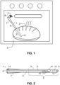
- the Figure 1 shows a pen-shaped food thermometer 1, which is inserted into a bread dough 2.
- the bread dough 2 is in an oven 3 and is heated.
- the food thermometer 1 measures temperatures and transmits measured temperatures by a radio unit 4 to an external device.
- the external device can be used to control the bread preparation.
- the front part of the food thermometer 1, which is to be inserted into the food 2, is the measuring sensor 5 of the food thermometer 1. Inside the measuring sensor 5 there is at least one temperature sensor. So that the measuring sensor 5 can be easily inserted into a food 2, the measuring sensor 5 comprises a tip 6.
- the measuring sensor 5 can be limited to a front third or a front half of the food thermometer 1.
- the rear part of the food thermometer 1 comprises a casing made of a heat-insulating plastic material such as rubber or elastomer, which serves as a handle 7.
- the rear end of the food thermometer 1 is formed by a heat conductor 8.
- the heat conductor 8 extends inside the housing 9 in the direction of the measuring sensor 5.
- the heat conductor 8 can be made of copper, for example.
- the housing 9 can be made of stainless steel or aluminum, for example.
- thermometer 1 is designed and suitable to be inserted into a foodstuff 2. It is therefore a penetration food thermometer.
- the rear end of the food thermometer 1 can also include one or more temperature sensors in order to be able to measure the ambient temperature during the preparation of a meal.
- the Figure 2 shows a section through an electric penetration food thermometer 1, which is similar to the Figure 1 shown electric penetration food thermometer 1.
- the energy converter 10 is constructed like a Peltier element.
- the essentially rod-shaped heat conductor 8 contacts the energy converter 10 in such a way that it borders on an electrical contact point of the energy converter 10.
- Another heat conductor 11 borders on the other electrical contact point of the energy converter 10.
- the other heat conductor 11 is also connected to the housing 9.
- the other heat conductor 11 can also be made of copper.
- a temperature sensor 13 is located at the rear end of the food thermometer 1.
- the two temperature sensors 12 and 13 are electrically connected to control electronics 14 of the food thermometer 1.
- the energy converter 10 is electrically connected to a battery 15 which is located between the temperature sensor 12 and the control electronics 14.
- the control electronics 14 comprises a wireless radio unit.
- the control electronics 14 can be electrically connected to the Heat conductor 8.
- the essentially rod-shaped heat conductor 8 then serves as an antenna for the radio unit of the control electronics 14.
- the control electronics 14 can be arranged, for example, between the energy converter 10 and the battery 15.
- the sensor 5 of the food thermometer 1 is to be inserted into a food. Once this has happened and the food 2 is in a heated oven 3, the rear end 8 of the food thermometer 1 is heated. The heat is transported to the first electrical contact point of the energy converter 10 via the essentially rod-shaped heat conductor 8.
- the sensor 5 is thermally shielded by the food 2.
- the part of the housing 9 that belongs to the sensor 5 is therefore initially barely heated and remains relatively cool.
- the second electrical contact point of the energy converter 10 is therefore kept cool via the other heat conductor 11. The energy converter 10 then generates electrical current with which the battery 15 can be charged.
- the temperature sensor 12 can measure the temperature inside a food.
- the temperature sensor 13 can measure the ambient temperature during the preparation of a meal.
- An electrical conductor can be attached to the rod-shaped heat conductor 8, which connects the temperature sensor 13 at the rear end of the penetration food thermometer to the control electronics 14.
- the heat conductor 8 can therefore also be used to suitably fix one or more electrical cables
- a hollow-cylindrical energy converter 10 with an essentially rod-shaped heat conductor 8 for a piercing food thermometer is shown.
- the rod-shaped heat conductor 8 leads into the hollow-cylindrical energy converter 10 in order to supply heat to an electrical contact point of the energy converter 10.
- Electrical connections 16 connect the energy converter 10 to the control electronics 14 in order to supply the control electronics 14 with power.
- An electrical conductor 17 is also connected to the control electronics 14 and the heat conductor 8.
- the heat conductor 8 can now, for example, serve as an antenna for a radio unit of the control electronics 14.
- the hollow-cylindrical shape enables the use of a significantly larger area to generate power.
- the hollow-cylindrical shape can directly contact the housing of the food thermometer 1 over a large area in the area of the temperature sensor. It Higher efficiencies are possible compared to the previously described embodiments.
- FIG. 4 a top view of energy converters 10 for a piercing food thermometer arranged one above the other is shown, which are separated from one another by a heat-conducting layer 18.
- a rod-shaped heat conductor 8 leads into the heat-conducting layer 18.
- the heat-conducting layer 18 can be made of copper like the rod-shaped heat conductor 8. However, other materials that conduct heat well are also possible.
- Thermally insulating layers 19 border the heat-conducting layer 18 and partly the energy converter 10 on the sides. The thermally insulating layers 19 prevent the areas of the energy converter 10 that are supposed to be kept cool from heating up.
- the thermally insulating layers 19 can, for example, extend into the heat-conducting layer 18 in the manner of a curvature or tip in order to improve thermal insulation.
- Thermally conductive layers 11 border the respective energy converter 10 on the top and bottom. The surface can be curved in order to ensure good contact with the adjacent housing of the penetration food thermometer.
- the Figure 4 The energy converters 10 shown can be cuboid-shaped. For example, additional energy converters can be arranged in pairs in front of and/or behind them.
- the energy converter 10 comprises two outer ceramic layers 20 which are good thermal conductors.
- the two ceramic layers 20 can be thermally separated from one another on the outside by a heat-insulating, sufficiently temperature-stable material 21.
- Inside the energy converter 10 there are alternating conductors A and B, for example made of metal.
- the material of conductor A differs from the material of conductor B.
- Only the ends of the electrical conductors A and B are electrically connected to one another in pairs and offset as shown. This creates two different contact points 23 and 24.
- One contact point 23 borders on one outer ceramic layer 20.
- the other contact point 24 borders on the other outer ceramic layer 20. If the two different ceramic layers 20 are heated to different temperatures, an electrical current is generated.
- Electrical conductors 16 lead out of the energy converter 10 and can, for example, contact a battery in order to charge it.
- the ceramic layers 20 can be flat.
- the energy converter 10 can then be cuboid-shaped.
- the layers 20 can also be the outer and inner shell of a hollow cylinder.
- the energy converter 10 can then be hollow-cylindrical.
Landscapes
- Physics & Mathematics (AREA)
- General Physics & Mathematics (AREA)
- Measuring Temperature Or Quantity Of Heat (AREA)
Claims (12)
- Thermomètre alimentaire à piquer électrique (1) avec une sonde de mesure allongée (5), avec un capteur de température (12) à l'intérieur de la sonde de mesure (5), avec un convertisseur d'énergie (10) qui peut générer un courant électrique à partir d'une différence de température, avec un conducteur de chaleur (3), qui est relié de manière thermoconductrice au convertisseur d'énergie (10), dans lequel le convertisseur d'énergie (10) comprend deux conducteurs électriques (A, B) différents avec deux points de contact (23, 24) pour la génération de courant électrique au moyen de l'effet Seebeck, caractérisé en ce que
le conducteur thermique (8) sort de la sonde de mesure (5) lorsque le convertisseur d'énergie (10) est disposé à l'intérieur de la sonde de mesure (5) et que le conducteur thermique (8) rentre dans la sonde de mesure (5) lorsque le convertisseur d'énergie (10) est disposé à l'extérieur de la sonde de mesure (5), dans lequel le conducteur thermique (8) est adjacent à l'un des deux points de contact (23, 24), dans lequel l'autre point de contact (23, 24) est relié de manière thermoconductrice à un boîtier (9) du thermomètre alimentaire (1) par l'intermédiaire d'un autre conducteur thermique (11) constitué de cuivre ou est directement adjacent au boîtier (9) du thermomètre alimentaire (1). - Thermomètre alimentaire (1) selon l'une des revendications précédentes, caractérisé en ce que le conducteur thermique (8) est constitué de cuivre.
- Thermomètre alimentaire (1) selon l'une des revendications précédentes, caractérisé en ce que le conducteur thermique (8) est entièrement ou au moins principalement en forme de tige.
- Thermomètre alimentaire (1) selon l'une des revendications précédentes, caractérisé en ce que le conducteur de chaleur (8) s'étend d'un tiers arrière du thermomètre alimentaire (1) jusqu'à un tiers avant du thermomètre alimentaire (1) et en ce que le convertisseur d'énergie (10) est disposé dans l'un des deux tiers.
- Thermomètre alimentaire (1) selon l'une des revendications précédentes, caractérisé en ce que le thermomètre alimentaire (1) comprend un dispositif radio et le conducteur de chaleur (8) est une antenne du dispositif radio ou un conducteur électrique qui est relié à une électronique du thermomètre alimentaire (1) ou à une batterie du thermomètre alimentaire (1).
- Thermomètre alimentaire (1) selon l'une des revendications précédentes, caractérisé en ce que le convertisseur d'énergie (10) est en forme de cylindre creux.
- Thermomètre alimentaire (1) selon l'une des revendications précédentes, caractérisé en ce que le conducteur thermique (8) est inséré dans la forme cylindrique creuse.
- Thermomètre alimentaire (1) selon l'une des revendications précédentes, caractérisé en ce qu'un isolateur thermique (19) est adjacent au conducteur thermique (8) à l'intérieur de la sonde de mesure (5).
- Thermomètre alimentaire (1) selon l'une des revendications précédentes, caractérisé en ce que la sonde de mesure (5) présente une extrémité pointue.
- Thermomètre alimentaire (1) selon l'une des revendications précédentes, caractérisé en ce que le thermomètre alimentaire (1) comprend une partie de préhension avec une zone de préhension (7) en matière plastique.
- Thermomètre alimentaire (1) selon l'une des revendications précédentes, caractérisé en ce que le thermomètre alimentaire (1) est en forme de stylo.
- Thermomètre alimentaire (1) selon l'une des revendications précédentes, caractérisé en ce que le thermomètre alimentaire (1) comprend une batterie et que le convertisseur d'énergie (10) est relié électriquement à la batterie du thermomètre alimentaire (1).
Priority Applications (6)
| Application Number | Priority Date | Filing Date | Title |
|---|---|---|---|
| EP21186000.2A EP4119911B1 (fr) | 2021-07-16 | 2021-07-16 | Thermomètre alimentaire plongeant |
| PL21186000.2T PL4119911T3 (pl) | 2021-07-16 | 2021-07-16 | Wkłuwany termometr do potraw |
| ES21186000T ES2982602T3 (es) | 2021-07-16 | 2021-07-16 | Termómetro de pincho para comida |
| AU2022203389A AU2022203389A1 (en) | 2021-07-16 | 2022-05-19 | Penetration food thermometer |
| US17/852,691 US20230015838A1 (en) | 2021-07-16 | 2022-06-29 | Penetration food thermometer |
| CN202210834040.0A CN115615571A (zh) | 2021-07-16 | 2022-07-14 | 刺入式食物温度计 |
Applications Claiming Priority (1)
| Application Number | Priority Date | Filing Date | Title |
|---|---|---|---|
| EP21186000.2A EP4119911B1 (fr) | 2021-07-16 | 2021-07-16 | Thermomètre alimentaire plongeant |
Publications (3)
| Publication Number | Publication Date |
|---|---|
| EP4119911A1 EP4119911A1 (fr) | 2023-01-18 |
| EP4119911C0 EP4119911C0 (fr) | 2024-05-29 |
| EP4119911B1 true EP4119911B1 (fr) | 2024-05-29 |
Family
ID=76958753
Family Applications (1)
| Application Number | Title | Priority Date | Filing Date |
|---|---|---|---|
| EP21186000.2A Active EP4119911B1 (fr) | 2021-07-16 | 2021-07-16 | Thermomètre alimentaire plongeant |
Country Status (6)
| Country | Link |
|---|---|
| US (1) | US20230015838A1 (fr) |
| EP (1) | EP4119911B1 (fr) |
| CN (1) | CN115615571A (fr) |
| AU (1) | AU2022203389A1 (fr) |
| ES (1) | ES2982602T3 (fr) |
| PL (1) | PL4119911T3 (fr) |
Families Citing this family (10)
| Publication number | Priority date | Publication date | Assignee | Title |
|---|---|---|---|---|
| USD1078501S1 (en) * | 2023-03-14 | 2025-06-10 | Shenzhen Hongkang International Electronic Technology Co., Ltd. | Food thermometer set |
| USD1046637S1 (en) * | 2023-03-14 | 2024-10-15 | Shenzhen Hongkang International Electronic Technology Co., Ltd. | Food thermometer |
| USD1046638S1 (en) * | 2023-03-14 | 2024-10-15 | Shenzhen Hongkang International Electronic Technology Co., Ltd. | Food thermometer |
| USD1046640S1 (en) * | 2023-03-14 | 2024-10-15 | Shenzhen Hongkang International Electronic Technology Co., Ltd. | Food thermometer |
| USD1046639S1 (en) * | 2023-07-13 | 2024-10-15 | Shenzhen Hongkang International Electronic Technology Co., Ltd. | Food thermometer |
| USD1056738S1 (en) * | 2023-08-23 | 2025-01-07 | Shenzhen Hongkang International Electronic Technology Co., Ltd. | Food thermometer set |
| USD1070613S1 (en) * | 2023-09-28 | 2025-04-15 | Shenzhen Yingboweiye Technology Co., Ltd. | Thermometer |
| USD1101580S1 (en) | 2024-01-31 | 2025-11-11 | Sharkninja Operating Llc | Temperature probe holder |
| USD1046642S1 (en) * | 2024-03-27 | 2024-10-15 | Finemold Technologies Co., Ltd | Meat thermometer |
| USD1046643S1 (en) * | 2024-03-27 | 2024-10-15 | Yaobing Deng | Meat thermometer |
Family Cites Families (10)
| Publication number | Priority date | Publication date | Assignee | Title |
|---|---|---|---|---|
| ITMO20040193A1 (it) * | 2004-07-23 | 2004-10-23 | Angelo Grandi Cucine Spa | Sistema e sonda per la rivealzione di un parametro |
| DE102004047756B4 (de) * | 2004-09-30 | 2012-03-01 | BSH Bosch und Siemens Hausgeräte GmbH | Temperatursensorvorrichtung |
| DE102007018245A1 (de) * | 2007-03-30 | 2008-10-02 | E.G.O. Elektro-Gerätebau GmbH | Temperatursonde für einen Ofen, Ofen und Verfahren zum Betrieb eines Ofens |
| CN101352307B (zh) * | 2008-09-16 | 2010-10-27 | 明高五金制品(深圳)有限公司 | 半导体制冷片温差发电电子测温锅 |
| DE202010017968U1 (de) * | 2010-05-19 | 2013-05-08 | Abb Technology Ag | Autonomer Temperaturtransmitter |
| ES2804535T3 (es) * | 2015-06-25 | 2021-02-08 | Apption Labs Ltd | Termómetro para alimentos |
| US20180353003A1 (en) * | 2017-06-08 | 2018-12-13 | Ashok Sabata | Novel Sensor Probe to Monitor Temperature during Cooking |
| US11579019B2 (en) * | 2019-08-15 | 2023-02-14 | Te Connectivity Solutions Gmbh | Wireless energy-harvesting sensor probe |
| ES3005845T3 (en) * | 2020-01-21 | 2025-03-17 | Vorwerk Co Interholding | Supply unit for generating electrical energy, kitchen utensil and kitchen system |
| CN114977888A (zh) * | 2021-04-23 | 2022-08-30 | 深圳市安服优智能互联科技有限公司 | 温差发电结构及测温传感器 |
-
2021
- 2021-07-16 EP EP21186000.2A patent/EP4119911B1/fr active Active
- 2021-07-16 PL PL21186000.2T patent/PL4119911T3/pl unknown
- 2021-07-16 ES ES21186000T patent/ES2982602T3/es active Active
-
2022
- 2022-05-19 AU AU2022203389A patent/AU2022203389A1/en active Pending
- 2022-06-29 US US17/852,691 patent/US20230015838A1/en not_active Abandoned
- 2022-07-14 CN CN202210834040.0A patent/CN115615571A/zh active Pending
Also Published As
| Publication number | Publication date |
|---|---|
| EP4119911A1 (fr) | 2023-01-18 |
| US20230015838A1 (en) | 2023-01-19 |
| CN115615571A (zh) | 2023-01-17 |
| PL4119911T3 (pl) | 2024-09-23 |
| EP4119911C0 (fr) | 2024-05-29 |
| ES2982602T3 (es) | 2024-10-17 |
| AU2022203389A1 (en) | 2023-02-02 |
Similar Documents
| Publication | Publication Date | Title |
|---|---|---|
| EP4119911B1 (fr) | Thermomètre alimentaire plongeant | |
| EP3501353B1 (fr) | Récipient de préparation pour une machine de cuisine | |
| EP3590351B1 (fr) | Cuve de préparation pourvue d'un dispositif de refroidissement | |
| EP2130016A2 (fr) | Sonde de température pour un four, four et procédé permettant de faire fonctionner un four | |
| EP1985983B1 (fr) | Sonde de mesure de la température, en particulier pour un appareil ménager | |
| DE102020104277A1 (de) | Kochgeschirr für ein Induktionskochfeld sowie Kochsystem | |
| EP3353514B1 (fr) | Sonde de mesure de température | |
| EP2295869A2 (fr) | Dispositif pour une enceinte de cuisson doté d'un élément de chauffage à couche épaisse | |
| DE102016125678A1 (de) | Heizelement für eine Küchenmaschine, Küchenmaschine, Kochgefäß sowie Verfahren zur Herstellung eines Heizelementes | |
| EP2268101B1 (fr) | Fond de creuset, appareil de cuisson et procédé de fonctionnement d'un tel appareil de cuisson | |
| EP1894441B1 (fr) | Dispositif de détection pour dispositif de cuisson | |
| EP3855146B1 (fr) | Unité d'alimentation permettant de produire de l'énergie électrique, ustensile de cuisine ainsi que système de cuisine | |
| DE10062371B4 (de) | Grillspieß und Grillgerät, insbesondere Backöfen | |
| DE102009027920A1 (de) | Gargerät | |
| DE102017130234A1 (de) | Bodenteil für eine Küchenmaschine | |
| DE202015105700U1 (de) | Vielzweckerhitzer | |
| DE4407797C2 (de) | Thermomesser | |
| DE102014106006A1 (de) | Heizelement mit Abschnitten verschiedener Heizleistungen sowie Gargerät | |
| DE4411850C2 (de) | Vorrichtung zur Erfassung von Temperaturen eines Gargefäßes | |
| DE102011086912B4 (de) | Gargeschirrvorrichtung und Systeme mit einer solchen Gargeschirrvorrichtung | |
| EP1612006A1 (fr) | Couteau chauffant | |
| DE3515414C2 (fr) | ||
| DE69903542T2 (de) | Temperaturfühler und haushaltelektrogerät mit einem solchen fühler | |
| EP3339827B1 (fr) | Capteur de température à coeur pour un appareil de cuisson, procédé de détection de la position d'un capteur de température à coeur ainsi que procédé de détermination de la conductivité thermique d'un appareil de cuisson | |
| EP2072694B1 (fr) | Evier |
Legal Events
| Date | Code | Title | Description |
|---|---|---|---|
| PUAI | Public reference made under article 153(3) epc to a published international application that has entered the european phase |
Free format text: ORIGINAL CODE: 0009012 |
|
| STAA | Information on the status of an ep patent application or granted ep patent |
Free format text: STATUS: THE APPLICATION HAS BEEN PUBLISHED |
|
| AK | Designated contracting states |
Kind code of ref document: A1 Designated state(s): AL AT BE BG CH CY CZ DE DK EE ES FI FR GB GR HR HU IE IS IT LI LT LU LV MC MK MT NL NO PL PT RO RS SE SI SK SM TR |
|
| STAA | Information on the status of an ep patent application or granted ep patent |
Free format text: STATUS: REQUEST FOR EXAMINATION WAS MADE |
|
| 17P | Request for examination filed |
Effective date: 20230309 |
|
| RBV | Designated contracting states (corrected) |
Designated state(s): AL AT BE BG CH CY CZ DE DK EE ES FI FR GB GR HR HU IE IS IT LI LT LU LV MC MK MT NL NO PL PT RO RS SE SI SK SM TR |
|
| REG | Reference to a national code |
Ref country code: DE Ref legal event code: R079 Ipc: G01K0001024000 Ref country code: DE Ref legal event code: R079 Ref document number: 502021003838 Country of ref document: DE Free format text: PREVIOUS MAIN CLASS: G01K0001160000 Ipc: G01K0001024000 |
|
| RIC1 | Information provided on ipc code assigned before grant |
Ipc: G01K 1/16 20060101ALI20231206BHEP Ipc: G01K 1/024 20210101AFI20231206BHEP |
|
| GRAP | Despatch of communication of intention to grant a patent |
Free format text: ORIGINAL CODE: EPIDOSNIGR1 |
|
| STAA | Information on the status of an ep patent application or granted ep patent |
Free format text: STATUS: GRANT OF PATENT IS INTENDED |
|
| INTG | Intention to grant announced |
Effective date: 20240125 |
|
| GRAS | Grant fee paid |
Free format text: ORIGINAL CODE: EPIDOSNIGR3 |
|
| GRAA | (expected) grant |
Free format text: ORIGINAL CODE: 0009210 |
|
| STAA | Information on the status of an ep patent application or granted ep patent |
Free format text: STATUS: THE PATENT HAS BEEN GRANTED |
|
| AK | Designated contracting states |
Kind code of ref document: B1 Designated state(s): AL AT BE BG CH CY CZ DE DK EE ES FI FR GB GR HR HU IE IS IT LI LT LU LV MC MK MT NL NO PL PT RO RS SE SI SK SM TR |
|
| REG | Reference to a national code |
Ref country code: CH Ref legal event code: EP |
|
| REG | Reference to a national code |
Ref country code: IE Ref legal event code: FG4D Free format text: LANGUAGE OF EP DOCUMENT: GERMAN |
|
| REG | Reference to a national code |
Ref country code: DE Ref legal event code: R096 Ref document number: 502021003838 Country of ref document: DE |
|
| U01 | Request for unitary effect filed |
Effective date: 20240529 |
|
| U07 | Unitary effect registered |
Designated state(s): AT BE BG DE DK EE FI FR IT LT LU LV MT NL PT SE SI Effective date: 20240604 |
|
| U20 | Renewal fee for the european patent with unitary effect paid |
Year of fee payment: 4 Effective date: 20240822 |
|
| PG25 | Lapsed in a contracting state [announced via postgrant information from national office to epo] |
Ref country code: IS Free format text: LAPSE BECAUSE OF FAILURE TO SUBMIT A TRANSLATION OF THE DESCRIPTION OR TO PAY THE FEE WITHIN THE PRESCRIBED TIME-LIMIT Effective date: 20240929 |
|
| PG25 | Lapsed in a contracting state [announced via postgrant information from national office to epo] |
Ref country code: HR Free format text: LAPSE BECAUSE OF FAILURE TO SUBMIT A TRANSLATION OF THE DESCRIPTION OR TO PAY THE FEE WITHIN THE PRESCRIBED TIME-LIMIT Effective date: 20240529 |
|
| PG25 | Lapsed in a contracting state [announced via postgrant information from national office to epo] |
Ref country code: GR Free format text: LAPSE BECAUSE OF FAILURE TO SUBMIT A TRANSLATION OF THE DESCRIPTION OR TO PAY THE FEE WITHIN THE PRESCRIBED TIME-LIMIT Effective date: 20240830 |
|
| REG | Reference to a national code |
Ref country code: ES Ref legal event code: FG2A Ref document number: 2982602 Country of ref document: ES Kind code of ref document: T3 Effective date: 20241017 |
|
| PG25 | Lapsed in a contracting state [announced via postgrant information from national office to epo] |
Ref country code: NO Free format text: LAPSE BECAUSE OF FAILURE TO SUBMIT A TRANSLATION OF THE DESCRIPTION OR TO PAY THE FEE WITHIN THE PRESCRIBED TIME-LIMIT Effective date: 20240829 Ref country code: IS Free format text: LAPSE BECAUSE OF FAILURE TO SUBMIT A TRANSLATION OF THE DESCRIPTION OR TO PAY THE FEE WITHIN THE PRESCRIBED TIME-LIMIT Effective date: 20240929 Ref country code: HR Free format text: LAPSE BECAUSE OF FAILURE TO SUBMIT A TRANSLATION OF THE DESCRIPTION OR TO PAY THE FEE WITHIN THE PRESCRIBED TIME-LIMIT Effective date: 20240529 Ref country code: GR Free format text: LAPSE BECAUSE OF FAILURE TO SUBMIT A TRANSLATION OF THE DESCRIPTION OR TO PAY THE FEE WITHIN THE PRESCRIBED TIME-LIMIT Effective date: 20240830 Ref country code: RS Free format text: LAPSE BECAUSE OF FAILURE TO SUBMIT A TRANSLATION OF THE DESCRIPTION OR TO PAY THE FEE WITHIN THE PRESCRIBED TIME-LIMIT Effective date: 20240829 |
|
| PG25 | Lapsed in a contracting state [announced via postgrant information from national office to epo] |
Ref country code: CZ Free format text: LAPSE BECAUSE OF FAILURE TO SUBMIT A TRANSLATION OF THE DESCRIPTION OR TO PAY THE FEE WITHIN THE PRESCRIBED TIME-LIMIT Effective date: 20240529 |
|
| PG25 | Lapsed in a contracting state [announced via postgrant information from national office to epo] |
Ref country code: SK Free format text: LAPSE BECAUSE OF FAILURE TO SUBMIT A TRANSLATION OF THE DESCRIPTION OR TO PAY THE FEE WITHIN THE PRESCRIBED TIME-LIMIT Effective date: 20240529 Ref country code: RO Free format text: LAPSE BECAUSE OF FAILURE TO SUBMIT A TRANSLATION OF THE DESCRIPTION OR TO PAY THE FEE WITHIN THE PRESCRIBED TIME-LIMIT Effective date: 20240529 |
|
| PG25 | Lapsed in a contracting state [announced via postgrant information from national office to epo] |
Ref country code: SM Free format text: LAPSE BECAUSE OF FAILURE TO SUBMIT A TRANSLATION OF THE DESCRIPTION OR TO PAY THE FEE WITHIN THE PRESCRIBED TIME-LIMIT Effective date: 20240529 |
|
| PG25 | Lapsed in a contracting state [announced via postgrant information from national office to epo] |
Ref country code: SM Free format text: LAPSE BECAUSE OF FAILURE TO SUBMIT A TRANSLATION OF THE DESCRIPTION OR TO PAY THE FEE WITHIN THE PRESCRIBED TIME-LIMIT Effective date: 20240529 Ref country code: SK Free format text: LAPSE BECAUSE OF FAILURE TO SUBMIT A TRANSLATION OF THE DESCRIPTION OR TO PAY THE FEE WITHIN THE PRESCRIBED TIME-LIMIT Effective date: 20240529 Ref country code: RO Free format text: LAPSE BECAUSE OF FAILURE TO SUBMIT A TRANSLATION OF THE DESCRIPTION OR TO PAY THE FEE WITHIN THE PRESCRIBED TIME-LIMIT Effective date: 20240529 Ref country code: CZ Free format text: LAPSE BECAUSE OF FAILURE TO SUBMIT A TRANSLATION OF THE DESCRIPTION OR TO PAY THE FEE WITHIN THE PRESCRIBED TIME-LIMIT Effective date: 20240529 |
|
| PG25 | Lapsed in a contracting state [announced via postgrant information from national office to epo] |
Ref country code: MC Free format text: LAPSE BECAUSE OF FAILURE TO SUBMIT A TRANSLATION OF THE DESCRIPTION OR TO PAY THE FEE WITHIN THE PRESCRIBED TIME-LIMIT Effective date: 20240529 |
|
| PLBE | No opposition filed within time limit |
Free format text: ORIGINAL CODE: 0009261 |
|
| STAA | Information on the status of an ep patent application or granted ep patent |
Free format text: STATUS: NO OPPOSITION FILED WITHIN TIME LIMIT |
|
| 26N | No opposition filed |
Effective date: 20250303 |
|
| PG25 | Lapsed in a contracting state [announced via postgrant information from national office to epo] |
Ref country code: IE Free format text: LAPSE BECAUSE OF NON-PAYMENT OF DUE FEES Effective date: 20240716 |
|
| U20 | Renewal fee for the european patent with unitary effect paid |
Year of fee payment: 5 Effective date: 20250729 |
|
| PGFP | Annual fee paid to national office [announced via postgrant information from national office to epo] |
Ref country code: ES Payment date: 20250819 Year of fee payment: 5 |
|
| PGFP | Annual fee paid to national office [announced via postgrant information from national office to epo] |
Ref country code: PL Payment date: 20250704 Year of fee payment: 5 |
|
| PGFP | Annual fee paid to national office [announced via postgrant information from national office to epo] |
Ref country code: GB Payment date: 20250724 Year of fee payment: 5 |
|
| PGFP | Annual fee paid to national office [announced via postgrant information from national office to epo] |
Ref country code: CH Payment date: 20250801 Year of fee payment: 5 |
|
| PG25 | Lapsed in a contracting state [announced via postgrant information from national office to epo] |
Ref country code: CY Free format text: LAPSE BECAUSE OF FAILURE TO SUBMIT A TRANSLATION OF THE DESCRIPTION OR TO PAY THE FEE WITHIN THE PRESCRIBED TIME-LIMIT; INVALID AB INITIO Effective date: 20210716 |
|
| PG25 | Lapsed in a contracting state [announced via postgrant information from national office to epo] |
Ref country code: HU Free format text: LAPSE BECAUSE OF FAILURE TO SUBMIT A TRANSLATION OF THE DESCRIPTION OR TO PAY THE FEE WITHIN THE PRESCRIBED TIME-LIMIT; INVALID AB INITIO Effective date: 20210716 |