EP3855408B1 - Verfahren zur vorhersage des fahrzeugverhaltens und vorrichtung zur vorhersage des fahrzeugverhaltens - Google Patents
Verfahren zur vorhersage des fahrzeugverhaltens und vorrichtung zur vorhersage des fahrzeugverhaltens Download PDFInfo
- Publication number
- EP3855408B1 EP3855408B1 EP18933829.6A EP18933829A EP3855408B1 EP 3855408 B1 EP3855408 B1 EP 3855408B1 EP 18933829 A EP18933829 A EP 18933829A EP 3855408 B1 EP3855408 B1 EP 3855408B1
- Authority
- EP
- European Patent Office
- Prior art keywords
- vehicle
- moving object
- course
- host vehicle
- detection
- Prior art date
- Legal status (The legal status is an assumption and is not a legal conclusion. Google has not performed a legal analysis and makes no representation as to the accuracy of the status listed.)
- Active
Links
Images








Classifications
-
- G—PHYSICS
- G08—SIGNALLING
- G08G—TRAFFIC CONTROL SYSTEMS
- G08G1/00—Traffic control systems for road vehicles
- G08G1/16—Anti-collision systems
- G08G1/167—Driving aids for lane monitoring, lane changing, e.g. blind spot detection
-
- B—PERFORMING OPERATIONS; TRANSPORTING
- B60—VEHICLES IN GENERAL
- B60R—VEHICLES, VEHICLE FITTINGS, OR VEHICLE PARTS, NOT OTHERWISE PROVIDED FOR
- B60R21/00—Arrangements or fittings on vehicles for protecting or preventing injuries to occupants or pedestrians in case of accidents or other traffic risks
-
- G—PHYSICS
- G06—COMPUTING OR CALCULATING; COUNTING
- G06T—IMAGE DATA PROCESSING OR GENERATION, IN GENERAL
- G06T7/00—Image analysis
-
- G—PHYSICS
- G08—SIGNALLING
- G08G—TRAFFIC CONTROL SYSTEMS
- G08G1/00—Traffic control systems for road vehicles
- G08G1/09—Arrangements for giving variable traffic instructions
-
- G—PHYSICS
- G08—SIGNALLING
- G08G—TRAFFIC CONTROL SYSTEMS
- G08G1/00—Traffic control systems for road vehicles
- G08G1/16—Anti-collision systems
-
- G—PHYSICS
- G08—SIGNALLING
- G08G—TRAFFIC CONTROL SYSTEMS
- G08G1/00—Traffic control systems for road vehicles
- G08G1/16—Anti-collision systems
- G08G1/166—Anti-collision systems for active traffic, e.g. moving vehicles, pedestrians, bikes
Definitions
- the present invention relates to a vehicle behavior prediction method and a vehicle behavior prediction device.
- Patent Document 1 Methods are known that inform a driver in a host vehicle of assistance information with regard to an oncoming vehicle traveling ahead of the host vehicle when the host vehicle is turning right at an intersection.
- the invention disclosed in Patent Document 1 defines the ranks of blind spots depending on what degree a following vehicle traveling behind an oncoming vehicle (a preceding vehicle) traveling straight on the oncoming road is entering a blind spot, according to a relationship between the type of the preceding vehicle and the type of the following vehicle.
- the invention disclosed in Patent Document 1 informs the driver of the assistance information in accordance with the rank of the blind spot defined.
- the document JP 2006 227811 A also constitutes background art to the present disclosure.
- Patent Document 1 Japanese Unexamined Patent Application Publication No. 2011-90582
- Patent Document 1 while defining the ranks of the blind spots depending on what degree the following vehicle is entering the blind spot caused by the preceding vehicle, fails to teach a prediction of a course that the following vehicle could take.
- the prediction of the course of the following vehicle, which contributes to smooth traveling of the host vehicle should be made at an early stage.
- the present invention provides a vehicle behavior prediction method and a vehicle behavior prediction device capable of predicting a course of a moving object traveling on the front side or the lateral side of a host vehicle at an early stage.
- a vehicle behavior prediction computer implemented method detects a position of an object, with respect to a host vehicle, located on a front side or a lateral side of the host vehicle, and detects a moving object traveling further than the object from the host vehicle.
- the vehicle behavior prediction method presumes a detection-available period from a point when the moving object is detected to a point when the moving object enters a blind spot region in a case in which the moving object travels in a predetermined course after being detected.
- the vehicle behavior prediction method compares the presumed detection-available period with an actual detection-available period from the point when the moving object is detected to a point when the moving object actually enters the blind spot region, and predicts a course of the moving object in accordance with the result of the comparison.
- the present invention can predict the course of the moving object traveling on the front side or the lateral side of the host vehicle at an early stage.
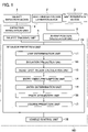
- the vehicle behavior prediction device includes an object detection device 1, a host-vehicle position estimation device 2, a map acquisition device 3, and a controller 100.
- the vehicle behavior prediction device may be used in either a vehicle having an autonomous driving function or a vehicle not equipped with the autonomous driving function.
- the vehicle behavior prediction device may also be used in a vehicle which can switch between autonomous driving and manual driving.
- autonomous driving refers to a state in which at least any of the brake, accelerator, and steering actuators is controlled without the operation of the occupant involved. Namely, any other actuators can be operated by the occupant.
- the autonomous driving is only required to be in a state in which any control such as acceleration/deceleration control and lateral-position control is executed.
- the term "manual driving" according to the present embodiment refers to a state in which the occupant operates the brake, the accelerator, and the steering, for example.
- the object detection device 1 includes object detection sensors, such as a laser radar, a millimeter-wave radar, and a camera, mounted on the host vehicle.
- the object detection device 1 detects objects around the host vehicle using the plural object detection sensors.
- the object detection device 1 also detects objects on the front side or the lateral side of the host vehicle.
- the object detection device 1 detects moving objects such as other vehicles, motorcycles, bicycles, and pedestrians, and stationary objects such as parked vehicles and constructions. For example, the object detection device 1 detects a position, an attitude (a yaw angle), a size, a velocity, acceleration, jerk, deceleration, and a yaw rate of a moving object or a stationary object with respect to the host vehicle.
- the host-vehicle position estimation device 2 includes a position detection sensor, such as a global positioning system (GPS) and a means of odometry, mounted on the host vehicle to measure an absolute position of the host vehicle.
- the host-vehicle position estimation device 2 measures the absolute position of the host vehicle, which is the position, the attitude, and the velocity of the host vehicle based on a predetermined reference point, by use of the position detection sensor.
- the map acquisition device 3 acquires map information indicating a structure of a road on which the host vehicle is traveling.
- the map information acquired by the map acquisition device 3 includes pieces of information on the road structure, such as absolute positions of lanes, and a connectional relation and a relative positional relation of lanes.
- the map information acquired by the map acquisition device 3 further includes pieces of information on facilities such as a parking lot and a gasoline station.
- the map acquisition device 3 may hold a map database storing the map information, or may acquire the map information from an external map data server through cloud computing.
- the map acquisition device 3 may acquire the map information through vehicle-to-vehicle communications or road-to-vehicle communications.
- the controller 100 predicts a course of another vehicle in accordance with the detection results obtained by the object detection device 1 and the host-vehicle position estimation device 2 and the information acquired by the map acquisition device 3.
- the controller 100 is a general-purpose microcomputer including a central processing unit (CPU), a memory, and an input-output unit.
- a computer program is installed on the microcomputer so as to function as the vehicle behavior prediction device.
- the microcomputer functions as a plurality of information processing circuits included in the vehicle behavior prediction device when the computer program is executed. While the present embodiment is illustrated with the case in which the software is installed to fabricate the information processing circuits included in the vehicle behavior prediction device, dedicated hardware for executing each information processing as described below can be prepared to compose the information processing circuits.
- the respective information processing circuits may be composed of individual hardware.
- the controller 100 includes, as the plural information processing circuits, a detection integration unit 4, an object tracking unit 5, an in-map position calculation unit 6, a behavior prediction unit 10, and a vehicle control unit 30.
- the behavior prediction unit 10 includes a lane determination unit 11, an intention prediction unit 12, a blind spot region calculation unit 13, an entry timing presumption unit 14, an entry determination unit 15, a track acquisition unit 16, and a course prediction unit 17.
- the detection integration unit 4 integrates several detection results obtained by the respective object detection sensors included in the object detection device 1, and outputs a single detection result per object. In particular, the detection integration unit 4 calculates the behavior of an object, which is the most reasonable and has the least error among pieces of the behavior of the object detected by the respective object detection sensors, in view of error characteristics of the respective object detection sensors. The detection integration unit 4 collectively evaluates the detection results obtained by the various sensors by a conventional sensor fusion method, so as to obtain a more accurate detection result for each object.
- the object tracking unit 5 tracks each object detected by the detection integration unit 4. In particular, the object tracking unit 5 makes a determination on the sameness (mapping) of the object detected at intervals in accordance with the behavior of the object output at different times, and tracks the object in accordance with the mapping result.
- the in-map position calculation unit 6 estimates the position of the host vehicle on the map according to the absolute position of the host vehicle acquired by the host-vehicle position estimation device 2 and the map data acquired by the map acquisition device 3.
- the lane determination unit 11 specifies the respective traveling lanes on the map in which the host vehicle and the object are traveling, in accordance with the object information acquired from the object tracking unit 5, and the own position estimated by the in-map position calculation unit 6.
- the intention prediction unit 12 predicts all possible lanes in which the object can travel forward, in accordance with the information on the traveling lane acquired from the lane determination unit 11 and the road structure. For example, when the object is traveling in a lane on a single-lane road, there is one possible lane in which the object can travel forward. When the object is traveling in a lane on a two-lane road, there are two possible lanes in which the object can travel forward, including the same traveling lane in which the object keeps traveling straight and a lane adjacent to the traveling lane.
- the intention prediction unit 12 may predict a behavior of the object in accordance with the position, the direction, and the attitude of the object.
- the blind spot region calculation unit 13 calculates a blind spot region from the host vehicle caused by an object around the host vehicle.
- the blind spot region refers to a region in which the object detection device 1 cannot detect another object because of the blind spot caused by the object.
- the entry timing presumption unit 14 presumes a detection-available period from a point when a moving object is detected to a point when the moving object enters a blind spot region, when the moving object keeps traveling straight after being detected. The explanations are made in detail below.
- the entry determination unit 15 determines whether the moving object enters the blind spot region before the detection-available period presumed by the entry timing presumption unit 14 has passed. In particular, the entry determination unit 15 compares the detection-available period presumed by the entry timing presumption unit 14 with an actual detection-available period so as to determine whether the actual detection-available period is shorter than the presumed detection-available period.
- the track acquisition unit 16 acquires a track of the moving object during the period from the point when the moving object is detected to the point immediately before the moving object enters the blind spot region.
- the course prediction unit 17 predicts a course of the moving object in accordance with the result determined by the entry determination unit 15.
- the course prediction unit 17 may predict the course of the moving object in accordance with the result determined by the entry determination unit 15 and the information acquired from the track acquisition unit 16.
- the vehicle control unit 30 controls various kinds of actuators (such as the steering actuator, the acceleration pedal actuator, and the brake actuator) using the information acquired by the respective sensors to execute the autonomous driving control or driving assistance control (for example, autonomous braking) so as to cause the host vehicle to travel along a course preliminarily set.
- actuators such as the steering actuator, the acceleration pedal actuator, and the brake actuator
- autonomous driving control or driving assistance control for example, autonomous braking
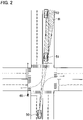
- the host vehicle 50 is traveling in the right lane on a two-lane road, and is to turn right at the next intersection.
- Another vehicle 51 is traveling in the right lane on the two-lane road, and is to turn right at the next intersection.
- the intention prediction unit 12 may predict whether the other vehicle 51 turns right at the next intersection in accordance with the position, the direction, the attitude, and the on/off state of the turn signals of the other vehicle 51.
- the other vehicle 51 is an oncoming vehicle traveling on the same road as the host vehicle 50 in the direction opposite to the direction in which the host vehicle 50 is traveling.
- Still another vehicle 52 is traveling behind the other vehicle 51.
- Reference sign R shown in Fig. 2 indicates a blind spot region from the host vehicle 50 caused by the other vehicle 51.
- the blind spot region R is calculated by the blind spot region calculation unit 13.
- the blind spot region calculation unit 13 calculates the blind spot region based on the position of the other vehicle 51 detected by the object detection device 1.
- the other vehicles 51 and 52 are present ahead of the host vehicle 50, and are detected by the object detection device 1.
- the object detection device 1 can detect the other vehicle 52 which has not entered the blind spot region R yet.
- One of the courses is that the other vehicle 52 keeps traveling straight to follow the other vehicle 51.
- the other course is that the other vehicle 52 changes the lanes.
- the case in which the other vehicle 52 enters the blind spot region R leads to the state in which the object detection device 1 cannot detect the other vehicle 52.
- the other vehicle 52 changes the lanes
- the course of the other vehicle 52 and the course of the host vehicle 50 can intersect with each other.
- the other vehicle 52 has priority over the host vehicle 50, and the host vehicle 50 then needs to decelerate or stop.
- the other vehicle 52 keeps traveling straight to follow the other vehicle 51
- the course of the other vehicle 52 does not intersect with the course of the host vehicle 50, since the other vehicle 52 is also turning right at the intersection.
- the host vehicle 50 can pass through the intersection without deceleration or stop.
- the situation illustrated in Fig. 2 thus requires the host vehicle 50 to predict the course of the other vehicle 52 at an early stage.
- the entry timing presumption unit 14 presumes the detection-available period from the point when the other vehicle 52 is detected to the point when the other vehicle 52 enters the blind spot region R, in the case in which the other vehicle 52 keeps traveling straight after being detected.
- the detection-available period is presumed on the assumption that the other vehicle 52 keeps traveling straight after being detected, in other words, the other vehicle 52 does not change its behavior after being detected.
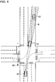
- Fig. 3 illustrates a traveling situation after the detection-available period T1 has passed since the traveling situation illustrated in Fig. 2 .
- the blind spot region R changes every moment depending on the position, the speed, and the like of each of the host vehicle 50 and the other vehicle 51.
- the entry timing presumption unit 14 presumes the detection-available period T1 from the point when the other vehicle 52 is detected to the point when the other vehicle 52 enters the blind spot region R, in accordance with, for example, the speeds and the positional relation between the host vehicle 50, the other vehicle 51, and the other vehicle 52.
- the case in which the other vehicle 52 cannot be detected after the detection-available period T1 has passed leads to the presumption with high probability that the other vehicle 52 keeps traveling straight.
- the course prediction unit 17 predicts that the other vehicle 52 keeps traveling straight.
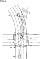
- Fig. 4 illustrates a traveling situation before the detection-available period T1 has passed since the traveling situation illustrated in Fig. 2 .
- the case in which the other vehicle 52 enters the blind spot region R before the detection-available period T1 has passed leads to the presumption with high probability that the other vehicle 52 changes the lanes.
- the reason for this is that the object detection device 1 can detect the other vehicle 52 until the detection-available period T1 has passed if the other vehicle 52 keeps traveling straight in the traveling situation illustrated in Fig. 2 .
- the course prediction unit 17 thus predicts that the other vehicle 52 has made a lane change when the other vehicle 52 enters the blind spot region R before the detection-available period T1 has passed, in other words, when the actual detection-available period is shorter than the presumed detection-available period T1.
- the determination of whether the other vehicle 52 enters the blind spot region R before the detection-available period T1 has passed, is made by the entry determination unit 15.
- the course prediction unit 17 may determine that the probability that the other vehicle 52 changes the lanes is high.
- the course prediction unit 17 may determine that the probability that the other vehicle 52 changes the lanes is low. The state in which the probability that the other vehicle 52 changes the lanes is low corresponds to the state in which the probability that the other vehicle 52 keeps traveling straight is high.
- the other vehicle 51 may be any type of vehicle, such as a standard-sized vehicle, a truck, and a bus.
- the other vehicle 52 is illustrated above as an automobile but is not limited to the automobile.
- the other vehicle 52 may be any moving object that can travel behind the other vehicle 51, such as a motorcycle or a bicycle.
- the entry determination unit 15 compares the detection-available period T1 presumed on the assumption that the other vehicle 52 keeps traveling straight with the actual detection-available period.
- the course prediction unit 17 then predicts that the other vehicle 52 keeps traveling straight when the actual detection-available period is longer than or equal to the presumed detection-available period T1, and predicts that the other vehicle 52 changes the lanes when the actual detection-available period is shorter than the presumed detection-available period T1.
- the detection-available period T1 may be a detection-available period in a case in which the other vehicle 52 is traveling in a predetermined course.
- the entry determination unit 15 compares the detection-available period T1 with the actual detection-available period so that the course prediction unit 17 can predict whether the other vehicle 52 is traveling in the predetermined course.
- the detection-available period T1 is a period on the assumption that the other vehicle 52 makes a lane change
- the course prediction unit 17 may predict that the other vehicle 52 is traveling straight when the actual detection-available period is longer than the presumed detection-available period T1, and may predict that the other vehicle 52 changes the lanes when the actual detection-available period is shorter than or equal to the presumed detection-available period T1.
- the detection-available period T1 is preferably the period on the assumption that the other vehicle 52 travels straight as described above, in order to presume the detection-available period T1 accurately.
- Fig. 2 to Fig. 4 illustrate the situations on the straight road
- the case to which the present invention is applied is not limited to the straight road.
- the present invention is applicable to a case of a curved road ( Fig. 6 to Fig. 8 ).
- Fig. 7 when the other vehicle 52 cannot be detected after the detection-available period T1 has passed, the course prediction unit 17 predicts that the other vehicle 52 travels straight.
- Fig. 7 when the other vehicle 52 cannot be detected after the detection-available period T1 has passed, the course prediction unit 17 predicts that the other vehicle 52 travels straight.
- the course prediction unit 17 predicts that the other vehicle 52 travels straight.
- the reason the other vehicle 51 is stopping as illustrated in Fig. 6 to Fig. 8 is that the other vehicle 51 is waiting for a pedestrian 60 to pass across the intersection.
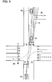
- the host vehicle 50 is traveling on a one-lane road, and is to turn right at the next intersection.
- the other vehicle 51 is also traveling on the one-lane road, and is to turn right at the next intersection.
- the other vehicle 52 is traveling behind the other vehicle 51.
- the object detection device 1 can detect the other vehicle 52 which has not entered the blind spot region R yet.
- Fig. 10 illustrates a traveling situation after the detection-available period T1 has passed since the traveling situation illustrated in Fig. 9 .
- the course prediction unit 17 predicts that the other vehicle 52 keeps traveling straight.
- Fig. 11 illustrates a traveling situation before the detection-available period T1 has passed since the traveling situation illustrated in Fig. 9 .
- the course prediction unit 17 thus predicts that the other vehicle 52 is turning left when the other vehicle 52 enters the blind spot region R before the detection-available period T1 has passed.
- Fig 9 to Fig. 11 illustrate the access road 70 as the location at which the other vehicle 52 can turn left
- the location at which the other vehicle 52 can turn left is not limited to the access road 70. Examples of locations at which the other vehicle 52 can turn left include a parking space, a gasoline station, and a convenience store.
- the host vehicle 50 is traveling on a one-lane road, and is to keep traveling straight at the next intersection.
- the other vehicle 52 is traveling on a one-lane road.
- Reference sign R shown in Fig. 12 indicates a blind spot region from the host vehicle 50 caused by a building 80.
- the other vehicle 52 and the building 80 are located on the lateral side (on the front lateral side) of the host vehicle 50, and are detected by the object detection device 1.
- the object detection device 1 can detect the other vehicle 52 which has not entered the blind spot region R yet.
- One of the courses is that the other vehicle 52 keeps traveling straight.
- the other course is that the other vehicle 52 turns right to enter the parking place 90.
- Fig. 13 illustrates a traveling situation after the detection-available period T1 has passed since the traveling situation illustrated in Fig. 12 .
- the course prediction unit 17 predicts that the other vehicle 52 keeps traveling straight.
- Fig. 14 illustrates a traveling situation before the detection-available period T1 has passed since the traveling situation illustrated in Fig. 12 .
- the case in which the other vehicle 52 enters the blind spot region R before the detection-available period T1 has passed leads to the presumption with high probability that the other vehicle 52 makes a right turn.
- the course prediction unit 17 thus predicts that the other vehicle 52 is turning right when the other vehicle 52 enters the blind spot region R before the detection-available period T1 has passed.
- step S101 the object detection device 1 detects an object (the other vehicle 51) ahead of the host vehicle 50 by use of the plural object detection sensors.
- the object detection device 1 also detects a moving object (the other vehicle 52) traveling further than the other vehicle 51 from the host vehicle 50.
- the process proceeds to step S103, and the detection integration unit 4 integrates the plural detection results obtained by the respective object detection sensors, and outputs a single detection result for the respective other vehicles.
- the object tracking unit 5 tracks each vehicle detected and integrated.
- step S105 the host-vehicle position estimation device 2 measures the absolute position of the host vehicle 50 by use of the position detection sensor.
- step S107 the map acquisition device 3 acquires the map information indicating the structure of the road on which the host vehicle 50 is traveling.
- step S109 the in-map position calculation unit 6 estimates the position of the host vehicle 50 on the map in accordance with the absolute position of the host vehicle 50 measured in step S105 and the map data acquired in step S107.
- step S111 the intention prediction unit 12 predicts the behavior (the course) of each of the other vehicle 51 and the other vehicle 52.
- Fig. 2 illustrates the case in which the intention prediction unit 12 predicts that the other vehicle 51 is turning right at the next intersection, in accordance with the position, the direction, the attitude, and the on/off state of the turn signals of the other vehicle 51.
- step S113 the blind spot region calculation unit 13 calculates the blind spot region R from the host vehicle 50 caused by the other vehicle 51, in accordance with the position of the other vehicle 51 detected by the object detection device 1.
- step S115 the entry timing presumption unit 14 presumes the detection-available period T1 from the point when the other vehicle 52 is detected to the point when the other vehicle 52 enters the blind spot region R, in the case in which the other vehicle 52 is traveling straight after being detected.
- step S119 the entry determination unit 15 determines whether the other vehicle 52 enters the blind spot region R before the detection-available period T1 has passed.
- step S121 and step S125 when the other vehicle 52 enters the blind spot region R before the detection-available period T1 has passed (Yes in step S119).
- step S121 the object detection device 1 acquires a distance between the other vehicle 52 and the host vehicle 50 immediately before the other vehicle 52 enters the blind spot region R.
- the process proceeds to step S123, and the course prediction unit 17 changes the probability of the behavior of the other vehicle 52 in accordance with the distance acquired in step S121.
- the change in the behavior of the moving object according to the present embodiment refers to one of changing lanes, making a left turn, and a making a right turn.
- the course prediction unit 17 increases the probability that the other vehicle 52 is making a lane change as the distance between the other vehicle 52 and the host vehicle 50 (not illustrated) is shorter. The reason for this is the errors of the sensors are smaller as the distance of a target from the host vehicle 50 is shorter.
- step S125 the track acquisition unit 16 acquires the track of the other vehicle 52 (the position of the other vehicle 52 in the lane) during the period from the point when the other vehicle 52 is detected to the point immediately before the other vehicle 52 enters the blind spot region R.
- the process proceeds to step S127, and the course prediction unit 17 increases the probability that the other vehicle 52 changes the behavior in accordance with the track acquired in step S125.
- the course prediction unit 17 increases the probability that the other vehicle 52 is making a lane change when the track of the other vehicle 52 during the period from the point when the other vehicle 52 is detected to the point immediately before the other vehicle 52 enters the blind spot region R, is different from the track indicating the straight forward movement.
- the course prediction unit 17 increases the probability that the other vehicle 52 is making a lane change when the track of the other vehicle 52 during the period from the point when the other vehicle 52 is detected to the point immediately before the other vehicle 52 enters the blind spot region R, is different from the track indicating the straight forward movement.
- the course prediction unit 17 increases the probability that the other vehicle 52 is making a left turn when the track of the other vehicle 52 during the period from the point when the other vehicle 52 is detected to the point when the other vehicle 52 enters the access road 70, is different from the track indicating the straight forward movement.
- the course prediction unit 17 may predict the course of the other vehicle 52 without executing the process in steps S121, S123, S125, and S127. Namely, the course prediction unit 17 may predict that the other vehicle 52 is making a lane change, making a left turn, or making a right turn, only in accordance with the state in which the other vehicle 52 enters the blind spot region R before the detection-available period T1 has passed. In the example illustrated in Fig.
- the course prediction unit 17 may increase the probability of the left turn of the other vehicle 52 to predict that the other vehicle has turned left when the track of the other vehicle 52 during the period from the point when the other vehicle 52 is detected to the point immediately before the other vehicle 52 enters the blind spot region R, indicates the track of traveling on the left side (on the shoulder edge side) in the traveling lane.
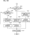
- step S129 the course prediction unit 17 acquires the track of the other vehicle 52 during the period from the point when the other vehicle 52 is detected to the point immediately before the other vehicle 52 enters the blind spot region R.
- the course prediction unit 17 increases the probability of the straight forward movement of the other vehicle 52 to predict that the other vehicle 52 keeps traveling straight (in step S137).
- the process proceeds to step S131, and the course prediction unit 17 acquires a change in speed of the other vehicle 52 immediately before the other vehicle 52 enters the blind spot region R.
- step S133 the course prediction unit 17 increases the probability that the other vehicle 52 is traveling straight in accordance with the change in speed acquired in step S131.
- the course prediction unit 17 may predict the course of the other vehicle 52 without executing the process in steps S129, S131, and S133. Namely, the course prediction unit 17 may predict that the other vehicle 52 keeps traveling straight only in accordance with the state in which the other vehicle 52 enters the blind spot region R after the detection-available period T1 has passed.
- the vehicle behavior prediction device may control the host vehicle in accordance with the predicted course of the other vehicle 52.
- the specific explanations are made below with reference to Fig. 16 .
- step S201 the vehicle control unit 30 acquires the course of the other vehicle 52 predicted by the course prediction unit 17.
- step S203 the vehicle control unit 30 acquires a course of the host vehicle 50 preliminarily set.
- step S205 the vehicle control unit 30 determines whether the course of the other vehicle 52 intersects with the course of the host vehicle 50.
- the process proceeds to step S207, and the vehicle control unit 30 then determines whether the road on which the other vehicle 52 is traveling has priority.
- the determination on the priority between the roads is made in accordance with a road structure, road signs, and traffic regulations.
- step S209 the vehicle control unit 30 calculates a speed profile for decelerating or stopping the host vehicle 50.
- the speed profile as used herein is to indicate the speed of the host vehicle 50 as a function of time.
- the course of the other vehicle 52 intersects with the course of the host vehicle 50, and the road on which the other vehicle 52 is traveling has priority.
- the vehicle control unit 30 calculates the speed profile for decelerating or stopping the host vehicle 50 so as to wait for the other vehicle 52 to pass through.
- the process proceeds to step S217, and the vehicle control unit 30 controls the brake actuator and the like in accordance with the speed profile so as to execute the autonomous driving control. This can prevent sudden deceleration.
- step S211 the vehicle control unit 30 calculates the speed profile depending on the degree of the probability of the course of the other vehicle 52. As illustrated in Fig. 3 , when the probability that the other vehicle 52 keeps traveling straight is high, the vehicle control unit 30 calculates the speed profile indicating a constant speed. The process proceeds to step S217, and the vehicle control unit 30 executes the autonomous driving control based on the speed profile. This enables the smooth autonomous driving accordingly.
- step S207 When the road on which the other vehicle 52 is traveling does not have priority (No in step S207), namely when the road on which the host vehicle 50 is traveling has priority, the process proceeds to step S215.
- step S215 the vehicle control unit 30 calculates the speed profile indicating a constant speed.
- step S217 the vehicle control unit 30 executes the autonomous driving control based on the speed profile. This enables the smooth autonomous driving accordingly.
- the vehicle behavior prediction device can achieve the following functional effects.
- the object detection device 1 detects an object (the other vehicle 51 or the building 80) on the front side or the lateral side of the host vehicle 50.
- the object detection device 1 also detects the position of the object with respect to the host vehicle 50 on the front side or the lateral side of the host vehicle 50.
- the object detection device 1 further detects a moving object (the other vehicle 52) traveling further than the object from the host vehicle 50.
- the blind spot region calculation unit 13 calculates the blind spot region R from the host vehicle 50 caused by the object, in accordance with the position of the object detected by the object detection device 1.
- the entry timing presumption unit 14 presumes the detection-available period T1 from the point when the moving object is detected to the point when the moving object enters the blind spot region R, in the case in which the moving object is traveling straight after being detected.
- the entry determination unit 15 determines whether the moving object enters the blind spot region R before the detection-available period T1 has passed.
- the vehicle control unit 30 predicts the course of the moving object in accordance with the determination result. In the example illustrated in Fig. 4 , the course prediction unit 17 predicts that the other vehicle 52 (the moving object) has changed the lanes when the other vehicle 52 enters the blind spot region R before the detection-available period T1 has passed.
- the vehicle behavior prediction device thus can predict the course of the moving object at an early stage.
- the object on the front side or the lateral side of the host vehicle 50 may be either the moving object (the other vehicle 51) or the stationary object (the building 80).
- the other vehicle 51 is an oncoming vehicle traveling on the same road as the host vehicle 50 in the direction opposite to the direction in which the host vehicle 50 is traveling.
- the stationary object is not limited to the building 80. Examples of stationary objects include parked vehicles.
- the detection-available period T1 may be the period from the point when the other vehicle 52 is detected to the period when the other vehicle 52 enters the blind spot region R in the case in which the other vehicle 52 is traveling along a predetermined course after being detected.
- the predetermined course includes the straight forward movement and the lane change.
- the object detection device 1 may compare the presumed detection-available period T1 with the actual detection-available period from the point when the other vehicle 52 is detected to the period when the other vehicle 52 actually enters the blind spot region R, so as to predict the course of the other vehicle 52 in accordance with the comparison result.
- the course prediction unit 17 predicts that the moving object has changed the lanes.
- the road on which the other vehicle 52 (the moving object) is traveling includes the plural lanes (the two lanes), and the other vehicle 52 is traveling in the lane of the plural lanes, other than the lane furthest from the host vehicle 50 when detecting the other vehicle 52.
- the lane furthest from the host vehicle 50 on the lane on which the other vehicle 52 is traveling is the left lane.
- the other vehicle 52 is traveling in the right lane.
- the course prediction unit 17 predicts that the other vehicle 52 has changed the lanes.
- the vehicle behavior prediction device thus can predict the course of the moving object at an early stage.
- the course prediction unit 17 predicts that the moving object has made a left turn.
- the entry-available place (the access road 70) is present on the left side along the road on which the other vehicle 52 (moving object) is traveling.
- the course prediction unit 17 predicts that the other vehicle 52 has made a left turn.
- the vehicle behavior prediction device thus can predict the course of the moving object at an early stage.
- the course prediction unit 17 predicts that the moving object has made a right turn.
- the entry-available place (the parking place 90) is present on the right side along the road on which the other vehicle 52 (moving object) is traveling.
- the course prediction unit 17 predicts that the other vehicle 52 has made a right turn.
- the vehicle behavior prediction device thus can predict the course of the moving object at an early stage.
- the course prediction unit 17 increases the probability of change in the behavior of the moving object, as the distance between the moving object and the host vehicle 50 is shorter.
- the change in the behavior of the moving object refers to one of changing lanes, making a left turn, and a making a right turn.
- the course prediction unit 17 increases the probability that the moving object has changed the lanes, has made a left turn, or has made a right turn, as the distance between the moving object and the host vehicle 50 is shorter. Since the errors of the sensors are smaller as the distance of a target from the host vehicle 50 is shorter, the course prediction unit 17 increases the probability as described above, so as to predict the course of the moving object with a high accuracy.
- the course prediction unit 17 increases the probability of change in the behavior of the moving object in accordance with the track of the moving object from the point when the moving object is detected to the point immediately before the moving object enters the blind spot region R.
- the course prediction unit 17 increases the probability that the other vehicle 52 has changed the lanes. The course prediction unit 17 thus increases the probability of change in the behavior in accordance with the track of the moving object, so as to predict the course of the moving object with a high accuracy.
- the course prediction unit 17 predicts that the moving object keeps traveling straight.
- the host vehicle 50 thus can pass through the intersection without waiting for the other vehicle 52 (the moving object), as illustrated in Fig. 3 . This contributes to smooth traveling of the host vehicle 50 accordingly.
- the course prediction unit 17 may increase the probability that the moving object keeps traveling straight, as the distance between the moving object and the host vehicle 50 is shorter.
- the course prediction unit 17 may increase the probability that the moving object keeps traveling straight. The course prediction unit 17 increases the probability as described above, so as to predict the course of the moving object with a high accuracy.
- the vehicle control unit 30 calculates the speed profile for the host vehicle 50 based on the course of the other vehicle 52 predicted by the course prediction unit 17. The vehicle control unit 30 then controls the host vehicle 50 in accordance with the calculated speed profile. This prevents sudden deceleration and achieves the smooth autonomous driving. For example, as illustrated in Fig. 4 , when the course of the other vehicle 52 intersects with the course of the host vehicle 50, and when the road on which the other vehicle 52 is traveling has priority, the vehicle control unit 30 calculates the speed profile for decelerating or stopping the host vehicle 50 so as to wait for the other vehicle 52 to pass through. The vehicle control unit 30 controls the brake actuator and the like in accordance with the speed profile so as to execute the autonomous driving control. This can prevent sudden deceleration.
- the vehicle control unit 30 may calculate the speed profile indicating a constant speed to execute the autonomous driving control based on the speed profile.
- the vehicle control unit 30 may calculate the speed profile indicating a constant speed to execute the autonomous driving control based on the speed profile. This enables the smooth autonomous driving accordingly.
- the respective functions described in the above embodiment can be implemented in single or plural processing circuits.
- the respective processing circuits include a programmed processing device, such as a processing device including an electric circuit.
- the respective processing circuits also include an application-specific integrated circuit (ASIC) configured to execute the functions described above, or other devices such as circuit components.
- ASIC application-specific integrated circuit
- the vehicle behavior prediction device can improve the functions of the computer.
Landscapes
- Physics & Mathematics (AREA)
- General Physics & Mathematics (AREA)
- Engineering & Computer Science (AREA)
- Computer Vision & Pattern Recognition (AREA)
- Theoretical Computer Science (AREA)
- Mechanical Engineering (AREA)
- Traffic Control Systems (AREA)
Claims (17)
- Computerimplementiertes Verfahren für Vorhersage von Verhalten eines Fahrzeugs, das umfasst:Erfassen einer Position eines Objektes in Bezug auf ein Host-Fahrzeug (50), das sich an einer Vorderseite oder einer Längsseite des Host-Fahrzeugs (50) befindet, unter Einsatz eines Sensors (1), der an dem Host-Fahrzeug (50) installiert ist;Erfassen eines sich bewegenden Objektes (52), das sich weiter als das Objekt von dem Host-Fahrzeug (50) entfernt bewegt, unter Einsatz des Sensors (1);Berechnen eines durch das Objekt verursachten Totwinkel-Bereiches (R) von dem Host-Fahrzeug (50) aus, in dem der Sensor (1) nicht erfassen kann, auf Basis der Position;Annehmen eines Zeitraums möglicher Erfassung von einem Punkt, an dem das sich bewegende Objekt (52) erfasst wird, bis zu einem Punkt, an dem das sich bewegende Objekt (52) in den Totwinkel-Bereich (R) eintritt, wenn das sich bewegende Objekt (52), nachdem es erfasst worden ist, auf einer vorgegebenen Fahrstrecke sich bewegt;Vergleichen des angenommenen Zeitraums möglicher Erfassung mit einem tatsächlichen Zeitraum möglicher Erfassung von dem Punkt, an dem das sich bewegende Objekt (52) erfasst wird, bis zu einem Punkt, an dem das sich bewegende Objekt (52) tatsächlich in den Totwinkel-Bereich (R) eintritt; undVorhersagen einer Fahrstrecke des sich bewegenden Objektes (52) entsprechend einem Ergebnis des Vergleichs.
- Verfahren für Vorhersage von Verhalten eines Fahrzeugs nach Anspruch 1, wobei:die vorgegebene Fahrstrecke eine geradlinige Vorwärtsbewegung ist; unddie Fahrstrecke des sich bewegenden Objektes (52) entsprechend einem Ergebnis von Vergleich dahingehend vorhergesagt wird, ob der tatsächliche Zeitraum möglicher Erfassung kürzer ist als der angenommene Zeitraum möglicher Erfassung.
- Verfahren für Vorhersage von Verhalten eines Fahrzeugs nach Anspruch 1 oder 2, wobei das Objekt ein entgegenkommendes Fahrzeug ist, das in einer dem Host-Fahrzeug (50) entgegengesetzten Richtung auf einer Straße fährt, auf der auch das Host-Fahrzeug (50) fährt.
- Verfahren für Vorhersage von Verhalten eines Fahrzeugs nach Anspruch 1 oder 2, wobei das Objekt ein stationäres Objekt ist.
- Verfahren für Vorhersage von Verhalten eines Fahrzeugs nach einem der Ansprüche 1 bis 4, das des Weiteren umfasst, dass, wenn der tatsächliche Zeitraum möglicher Erfassung kürzer ist als der angenommene Zeitraum möglicher Erfassung, dann vorhergesagt wird, dass das sich bewegende Objekt (52) einen Spurwechsel vornimmt, wenn die vorgegebene Fahrstrecke eine geradlinige Vorwärtsbewegung ist, die Straße, auf der sich das sich bewegende Objekt (52) bewegt, eine Vielzahl von Fahrspuren enthält und sich das sich bewegende Objekt (52) auf einer anderen der Vielzahl von Fahrspuren als einer Fahrspur bewegt, die am weitesten von dem Host-Fahrzeug (50) entfernt ist, wenn das sich bewegende Objekt (52) erfasst wird.
- Verfahren für Vorhersage von Verhalten eines Fahrzeugs nach einem der Ansprüche 1 bis 5, das des Weiteren umfasst, dass, wenn der tatsächliche Zeitraum möglicher Erfassung kürzer ist als der angenommene Zeitraum möglicher Erfassung, dann vorhergesagt wird, dass das sich bewegende Objekt (52) nach links abbiegt, wenn die vorgegebene Fahrstrecke eine geradlinige Vorwärtsbewegung ist und an einer linken Seite der Straße, auf der sich das sich bewegende Objekt (52) bewegt, eine Stelle liegt, an der Einfahrt möglich ist.
- Verfahren für Vorhersage von Verhalten eines Fahrzeugs nach einem der Ansprüche 1 bis 6, das des Weiteren umfasst, dass, wenn der tatsächliche Zeitraum möglicher Erfassung kürzer ist als der angenommene Zeitraum möglicher Erfassung, dann vorhergesagt wird, dass das sich bewegende Objekt (52) nach rechts abbiegt, wenn die vorgegebene Fahrstrecke eine geradlinige Vorwärtsbewegung ist und an einer rechten Seite der Straße, auf der sich das sich bewegende Objekt (52) bewegt, eine Stelle liegt, an der Einfahrt möglich ist.
- Verfahren für Vorhersage von Verhalten eines Fahrzeugs nach einem der Ansprüche 1 bis 7, das des Weiteren umfasst:Erhöhen einer Wahrscheinlichkeit dahingehend, dass ein Verhalten des sich bewegenden Objektes (52) geändert wird, wenn ein Abstand zwischen dem sich bewegenden Objekt (52) und dem Host-Fahrzeug (50) kürzer ist, wenn die vorgegebene Fahrstrecke eine geradlinige Vorwärtsbewegung ist und der tatsächliche Zeitraum möglicher Erfassung kürzer ist als der angenommene Zeitraum möglicher Erfassung; sowieVorhersagen der Fahrstrecke des sich bewegenden Objektes (52) entsprechend der Wahrscheinlichkeit und dem Ergebnis des Vergleichs.
- Verfahren für Vorhersage von Verhalten eines Fahrzeugs nach einem der Ansprüche 1 bis 7, das des Weiteren umfasst:Erhöhen einer Wahrscheinlichkeit dahingehend, dass ein Verhalten des sich bewegenden Objektes (52) geändert wird, entsprechend einem Fahrweg des sich bewegenden Objektes (52) von dem Punkt, an dem das sich bewegende Objekt (52) erfasst wird, bis zu einem Punkt unmittelbar vor Eintreten des sich bewegenden Objektes (52) in den Totwinkel-Bereich (R), wenn die vorgegebene Fahrstrecke eine geradlinige Vorwärtsbewegung ist und der tatsächliche Zeitraum möglicher Erfassung kürzer ist als der angenommene Zeitraum möglicher Erfassung; undVorhersagen der Fahrstrecke des sich bewegenden Objektes (52) entsprechend der Wahrscheinlichkeit und dem Ergebnis des Vergleichs.
- Verfahren für Vorhersage von Verhalten eines Fahrzeugs nach einem der Ansprüche 1 bis 9, das des Weiteren umfasst, dass vorhergesagt wird, dass das sich bewegende Objekt (52) sich geradeaus bewegt, wenn die vorgegebene Fahrstrecke eine geradlinige Vorwärtsbewegung ist, und der tatsächliche Zeitraum möglicher Erfassung länger ist als oder genauso lang wie der angenommene Zeitraum möglicher Erfassung.
- Verfahren für Vorhersage von Verhalten eines Fahrzeugs nach Anspruch 10, das des Weiteren umfasst:Erhöhen einer Wahrscheinlichkeit dahingehend, dass das sich bewegende Objekt (52) sich geradeaus bewegt, wenn ein Abstand zwischen dem sich bewegenden Objekt (52) und dem Host-Fahrzeug (50) kürzer ist, oder Erhöhen der Wahrscheinlichkeit dahingehend, dass das sich bewegende Objekt (52) sich geradeaus bewegt, entsprechend einem Fahrweg des sich bewegenden Objektes (52) von dem Punkt, an dem das sich bewegende Objekt (52) erfasst wird, bis zu einem Punkt unmittelbar vor Eintreten des sich bewegenden Objektes (52) in den Totwinkel-Bereich (R); undVorhersagen, dass das bewegte Objekt (52) sich geradeaus bewegt.
- Verfahren für Vorhersage von Verhalten eines Fahrzeugs nach einem der Ansprüche 1 bis 11, das des Weiteren Berechnen eines Geschwindigkeitsprofils umfasst, das eine Geschwindigkeit des Host-Fahrzeugs (50) als eine Funktion der Zeit entsprechend einem Ergebnis der Vorhersage der Fahrstrecke des sich bewegenden Objektes (52) angibt.
- Fahrzeug-Steuerungsverfahren zum Steuern des Host-Fahrzeugs (50) unter Einsatz des Verfahrens für Vorhersage von Verhalten eines Fahrzeugs nach Anspruch 12, wobei das Fahrzeug-Steuerungsverfahren umfasst:Berechnen des Geschwindigkeitsprofils zum Abbremsen oder Anhalten des Host-Fahrzeugs (50), wenn die Fahrstrecke des sich bewegenden Objektes (52) eine Fahrstrecke des Host-Fahrzeugs (50) kreuzt und eine Straße, auf der das sich bewegende Objekt (52) sich bewegt, Vorfahrt hat; sowieSteuern des Host-Fahrzeugs (50) entsprechend dem Geschwindigkeitsprofil.
- Fahrzeug-Steuerungsverfahren zum Steuern des Host-Fahrzeugs (50) unter Einsatz des Verfahrens für Vorhersage von Verhalten eines Fahrzeugs nach Anspruch 12, wobei das Fahrzeug-Steuerungsverfahren umfasst:Berechnen des Geschwindigkeitsprofils, das eine konstante Geschwindigkeit anzeigt, wenn die Fahrstrecke des sich bewegenden Objektes (52) eine Fahrstrecke des Host-Fahrzeugs (50) kreuzt und eine Straße, auf der das sich bewegende Objekt (52) sich bewegt, Vorfahrt hat; sowieSteuern des Host-Fahrzeugs (50) entsprechend dem Geschwindigkeitsprofil.
- Fahrzeug-Steuerungsverfahren zum Steuern des Host-Fahrzeugs (50) unter Einsatz des Verfahrens für Vorhersage von Verhalten eines Fahrzeugs nach Anspruch 12, wobei das Fahrzeug-Steuerungsverfahren umfasst:Berechnen des Geschwindigkeitsprofils, das eine konstante Geschwindigkeit angibt, wenn die Fahrstrecke des sich bewegenden Objektes (52) eine Fahrstrecke des Host-Fahrzeugs nicht kreuzt; undSteuern des Host-Fahrzeugs (50) entsprechend dem Geschwindigkeitsprofil.
- Vorrichtung für Vorhersage von Verhalten eines Fahrzeugs, die umfasst:einen Sensor (1), der so ausgeführt ist, dass er eine Position eines Objektes in Bezug auf ein Host-Fahrzeug (50), das sich an einer Vorderseite oder einer Längsseite des Host-Fahrzeugs (50) befindet, sowie ein sich bewegendes Objekt (52) erfasst, das sich weiter als das Objekt von dem Host-Fahrzeug (50) entfernt bewegt; sowieeine Steuerungs-Einheit (100),wobei die Steuerungs-Einheit (100) ausgeführt ist zum:Berechnen eines durch das Objekt verursachten Totwinkel-Bereiches (R) von dem Host-Fahrzeug (50) aus, in dem der Sensor (1) nicht erfassen kann, auf Basis der durch den Sensor (1) erfassten Position;Annehmen eines Zeitraums möglicher Erfassung von einem Punkt, an dem das sich bewegende Objekt (52) erfasst wird, bis zu einem Punkt, an dem das sich bewegende Objekt (52) in den Totwinkel-Bereich (R) eintritt, wenn das sich bewegende Objekt, nachdem es durch den Sensor (1) erfasst worden ist, sich auf einer vorgegebenen Fahrstrecke bewegt;Vergleichen des angenommenen Zeitraums möglicher Erfassung mit einem tatsächlichen Zeitraum möglicher Erfassung von dem Punkt, an dem das sich bewegende Objekt (52) erfasst wird, bis zu einem Punkt, an dem das sich bewegende Objekt (52) tatsächlich in den Totwinkel-Bereich (R) eintritt; undVorhersagen einer Fahrstrecke des sich bewegenden Objektes (52) entsprechend einem Ergebnis des Vergleichs.
- Vorrichtung für Vorhersage von Verhalten eines Fahrzeugs nach Anspruch 16, wobei:die vorgegebene Fahrstrecke eine geradlinige Vorwärtsbewegung ist; unddie Steuerungs-Einheit (100) die Fahrstrecke des sich bewegenden Objektes (52) entsprechend einem Ergebnis von Vergleich dahingehend vorhersagt, ob der tatsächliche Zeitraum möglicher Erfassung kürzer ist als der angenommene Zeitraum möglicher Erfassung.
Applications Claiming Priority (1)
| Application Number | Priority Date | Filing Date | Title |
|---|---|---|---|
| PCT/IB2018/001582 WO2020058740A1 (ja) | 2018-09-17 | 2018-09-17 | 車両挙動予測方法及び車両挙動予測装置 |
Publications (3)
| Publication Number | Publication Date |
|---|---|
| EP3855408A1 EP3855408A1 (de) | 2021-07-28 |
| EP3855408A4 EP3855408A4 (de) | 2021-09-22 |
| EP3855408B1 true EP3855408B1 (de) | 2022-11-02 |
Family
ID=69888388
Family Applications (1)
| Application Number | Title | Priority Date | Filing Date |
|---|---|---|---|
| EP18933829.6A Active EP3855408B1 (de) | 2018-09-17 | 2018-09-17 | Verfahren zur vorhersage des fahrzeugverhaltens und vorrichtung zur vorhersage des fahrzeugverhaltens |
Country Status (7)
| Country | Link |
|---|---|
| US (1) | US11302197B2 (de) |
| EP (1) | EP3855408B1 (de) |
| JP (1) | JP7031005B2 (de) |
| KR (1) | KR102657973B1 (de) |
| CN (1) | CN112703541B (de) |
| RU (1) | RU2762150C1 (de) |
| WO (1) | WO2020058740A1 (de) |
Families Citing this family (7)
| Publication number | Priority date | Publication date | Assignee | Title |
|---|---|---|---|---|
| WO2021053390A1 (en) * | 2019-09-17 | 2021-03-25 | Mobileye Vision Technologies Ltd. | Systems and methods for predicting blind spot incursions |
| JP7289760B2 (ja) * | 2019-09-18 | 2023-06-12 | 日立Astemo株式会社 | 電子制御装置 |
| CN111942407B (zh) * | 2020-07-31 | 2022-09-23 | 商汤集团有限公司 | 轨迹预测方法、装置、设备及存储介质 |
| US12542054B2 (en) | 2021-11-19 | 2026-02-03 | Qualcomm Incorporated | Managing vehicle behavior based on predicted behavior of other vehicles |
| US20230159025A1 (en) * | 2021-11-19 | 2023-05-25 | Qualcomm Incorporated | Managing Vehicle Behavior Based On Predicted Behavior Of Other Vehicles |
| CN116639151B (zh) * | 2023-05-30 | 2023-11-28 | 武汉理工大学 | 基于人行道盲区行人存在性预测的无人车控制方法及系统 |
| KR20250007871A (ko) * | 2023-07-06 | 2025-01-14 | 현대자동차주식회사 | 자율 주행 제어 장치 및 그 방법 |
Family Cites Families (25)
| Publication number | Priority date | Publication date | Assignee | Title |
|---|---|---|---|---|
| JP4517393B2 (ja) * | 2005-02-16 | 2010-08-04 | 株式会社デンソー | 運転支援装置 |
| JP4768499B2 (ja) | 2006-04-17 | 2011-09-07 | アルパイン株式会社 | 車載周辺他車検出装置 |
| JP2008041058A (ja) * | 2006-08-10 | 2008-02-21 | Sumitomo Electric Ind Ltd | 死角移動体を報知するための報知システム、画像処理装置、車載装置及び報知方法 |
| JP4709099B2 (ja) * | 2006-08-30 | 2011-06-22 | 三菱電機株式会社 | 評価装置、交通情報システム、車載装置、評価装置の評価方法、交通情報システムの交通情報処理方法、車載装置の車載情報処理方法、評価装置の評価プログラムおよび車載装置の車載情報処理プログラム |
| JP5469430B2 (ja) | 2009-10-23 | 2014-04-16 | 富士重工業株式会社 | 右折時運転支援装置 |
| JP5573418B2 (ja) * | 2010-06-29 | 2014-08-20 | トヨタ自動車株式会社 | 警報装置 |
| JP5766924B2 (ja) * | 2010-09-13 | 2015-08-19 | 三菱電機株式会社 | 車載装置、進入時間算出方法および進入時間算出プログラム |
| RU2546547C1 (ru) * | 2011-04-13 | 2015-04-10 | Ниссан Мотор Ко., Лтд. | Устройство помощи при вождении и способ обнаружения транспортного средства рядом с ним |
| CN103609101A (zh) * | 2011-06-16 | 2014-02-26 | 爱信精机株式会社 | 车辆周边监视装置 |
| JP5895258B2 (ja) * | 2011-12-22 | 2016-03-30 | 三洋テクノソリューションズ鳥取株式会社 | 移動体通信装置及び走行支援方法 |
| BR112015000983A2 (pt) * | 2012-07-17 | 2017-06-27 | Nissan Motor | sistema de assistência de condução e método de assistência de condução |
| US20150232028A1 (en) * | 2014-02-14 | 2015-08-20 | Magnadyne Corporation | Exterior Mirror Blind Spot Warning Display and Video Camera |
| WO2015152304A1 (ja) * | 2014-03-31 | 2015-10-08 | エイディシーテクノロジー株式会社 | 運転支援装置、及び運転支援システム |
| JP2017114155A (ja) * | 2015-12-21 | 2017-06-29 | 三菱自動車工業株式会社 | 運転支援装置 |
| US9994151B2 (en) * | 2016-04-12 | 2018-06-12 | Denso International America, Inc. | Methods and systems for blind spot monitoring with adaptive alert zone |
| US10380439B2 (en) * | 2016-09-06 | 2019-08-13 | Magna Electronics Inc. | Vehicle sensing system for detecting turn signal indicators |
| JP6332384B2 (ja) * | 2016-09-29 | 2018-05-30 | マツダ株式会社 | 車両用物標検出システム |
| KR101827698B1 (ko) * | 2016-11-01 | 2018-02-12 | 현대자동차주식회사 | 차량 및 그 제어방법 |
| US20190333373A1 (en) * | 2017-01-20 | 2019-10-31 | Nissan Motor Co., Ltd. | Vehicle Behavior Prediction Method and Vehicle Behavior Prediction Apparatus |
| US10453344B2 (en) * | 2017-02-16 | 2019-10-22 | Panasonic Intellectual Corporation Of America | Information processing apparatus and non-transitory recording medium |
| WO2018158911A1 (ja) * | 2017-03-02 | 2018-09-07 | 日産自動車株式会社 | 運転支援方法及び運転支援装置 |
| JP6768604B2 (ja) * | 2017-07-03 | 2020-10-14 | 日立オートモティブシステムズ株式会社 | 車両制御装置 |
| US11150342B2 (en) * | 2017-09-07 | 2021-10-19 | Magna Electronics Inc. | Vehicle radar sensing system with surface segmentation using interferometric statistical analysis |
| CN109801508B (zh) * | 2019-02-26 | 2021-06-04 | 百度在线网络技术(北京)有限公司 | 路口处障碍物的运动轨迹预测方法及装置 |
| CN111272165B (zh) * | 2020-02-27 | 2020-10-30 | 清华大学 | 一种基于特征点标定的智能车定位方法 |
-
2018
- 2018-09-17 EP EP18933829.6A patent/EP3855408B1/de active Active
- 2018-09-17 US US17/276,221 patent/US11302197B2/en active Active
- 2018-09-17 KR KR1020217008557A patent/KR102657973B1/ko active Active
- 2018-09-17 JP JP2020547454A patent/JP7031005B2/ja active Active
- 2018-09-17 RU RU2021110514A patent/RU2762150C1/ru active
- 2018-09-17 CN CN201880097536.6A patent/CN112703541B/zh active Active
- 2018-09-17 WO PCT/IB2018/001582 patent/WO2020058740A1/ja not_active Ceased
Also Published As
| Publication number | Publication date |
|---|---|
| KR20210057054A (ko) | 2021-05-20 |
| CN112703541A (zh) | 2021-04-23 |
| CN112703541B (zh) | 2022-09-20 |
| US20220028274A1 (en) | 2022-01-27 |
| WO2020058740A1 (ja) | 2020-03-26 |
| JP7031005B2 (ja) | 2022-03-07 |
| KR102657973B1 (ko) | 2024-04-16 |
| RU2762150C1 (ru) | 2021-12-16 |
| US11302197B2 (en) | 2022-04-12 |
| JPWO2020058740A1 (ja) | 2021-08-30 |
| EP3855408A4 (de) | 2021-09-22 |
| EP3855408A1 (de) | 2021-07-28 |
Similar Documents
| Publication | Publication Date | Title |
|---|---|---|
| EP3855408B1 (de) | Verfahren zur vorhersage des fahrzeugverhaltens und vorrichtung zur vorhersage des fahrzeugverhaltens | |
| EP3591638B1 (de) | Fahrassistenzverfahren und fahrassistenzvorrichtung | |
| US10994730B2 (en) | Traveling assistance method and traveling assistance device | |
| EP3627470A1 (de) | Bewegungsvorhersageverfahren für fahrassistenzvorrichtung und bewegungsvorhersagevorrichtung | |
| US11608062B2 (en) | Vehicle control method and vehicle control device | |
| US11433882B2 (en) | Method and device for performing an at least partially automated driving maneuver | |
| US20190258269A1 (en) | Vehicle control device | |
| US11780468B2 (en) | Vehicle-behavior prediction method and vehicle-behavior prediction device | |
| EP3764337A1 (de) | Fahrzeugfahrtassistenzverfahren und fahrzeugfahrtassistenzvorrichtung | |
| US20200385023A1 (en) | Vehicle control apparatus, vehicle, operation method of vehicle control apparatus, and non-transitory computer-readable storage medium | |
| US12291201B2 (en) | Travel control apparatus, vehicle, travel control method, and non-transitory computer-readable storage medium | |
| JP7143893B2 (ja) | 車両挙動予測方法及び車両挙動予測装置 | |
| US11260884B2 (en) | Vehicle control apparatus, vehicle, operation method of vehicle control apparatus, and non-transitory computer-readable storage medium | |
| US12115999B2 (en) | Method for predicting behavior of other vehicle, device for predicting behavior of other vehicle, and driving assistance method | |
| JP7223588B2 (ja) | 運転特性推定方法及び運転特性推定装置 | |
| JP2023010320A (ja) | 自動運転方法、自動運転システム、及び自動運転プログラム | |
| WO2025134343A1 (ja) | 走行制御方法及び走行制御装置 |
Legal Events
| Date | Code | Title | Description |
|---|---|---|---|
| STAA | Information on the status of an ep patent application or granted ep patent |
Free format text: STATUS: THE INTERNATIONAL PUBLICATION HAS BEEN MADE |
|
| PUAI | Public reference made under article 153(3) epc to a published international application that has entered the european phase |
Free format text: ORIGINAL CODE: 0009012 |
|
| STAA | Information on the status of an ep patent application or granted ep patent |
Free format text: STATUS: REQUEST FOR EXAMINATION WAS MADE |
|
| 17P | Request for examination filed |
Effective date: 20210401 |
|
| AK | Designated contracting states |
Kind code of ref document: A1 Designated state(s): AL AT BE BG CH CY CZ DE DK EE ES FI FR GB GR HR HU IE IS IT LI LT LU LV MC MK MT NL NO PL PT RO RS SE SI SK SM TR |
|
| A4 | Supplementary search report drawn up and despatched |
Effective date: 20210824 |
|
| RIC1 | Information provided on ipc code assigned before grant |
Ipc: G08G 1/16 20060101AFI20210818BHEP |
|
| DAV | Request for validation of the european patent (deleted) | ||
| DAX | Request for extension of the european patent (deleted) | ||
| RAP3 | Party data changed (applicant data changed or rights of an application transferred) |
Owner name: RENAULT S.A.S Owner name: NISSAN MOTOR CO., LTD. |
|
| GRAP | Despatch of communication of intention to grant a patent |
Free format text: ORIGINAL CODE: EPIDOSNIGR1 |
|
| STAA | Information on the status of an ep patent application or granted ep patent |
Free format text: STATUS: GRANT OF PATENT IS INTENDED |
|
| RAP3 | Party data changed (applicant data changed or rights of an application transferred) |
Owner name: RENAULT S.A.S Owner name: NISSAN MOTOR CO., LTD. |
|
| INTG | Intention to grant announced |
Effective date: 20220704 |
|
| GRAS | Grant fee paid |
Free format text: ORIGINAL CODE: EPIDOSNIGR3 |
|
| GRAA | (expected) grant |
Free format text: ORIGINAL CODE: 0009210 |
|
| STAA | Information on the status of an ep patent application or granted ep patent |
Free format text: STATUS: THE PATENT HAS BEEN GRANTED |
|
| AK | Designated contracting states |
Kind code of ref document: B1 Designated state(s): AL AT BE BG CH CY CZ DE DK EE ES FI FR GB GR HR HU IE IS IT LI LT LU LV MC MK MT NL NO PL PT RO RS SE SI SK SM TR |
|
| REG | Reference to a national code |
Ref country code: GB Ref legal event code: FG4D |
|
| REG | Reference to a national code |
Ref country code: CH Ref legal event code: EP Ref country code: AT Ref legal event code: REF Ref document number: 1529346 Country of ref document: AT Kind code of ref document: T Effective date: 20221115 |
|
| REG | Reference to a national code |
Ref country code: DE Ref legal event code: R096 Ref document number: 602018042747 Country of ref document: DE |
|
| REG | Reference to a national code |
Ref country code: IE Ref legal event code: FG4D |
|
| REG | Reference to a national code |
Ref country code: LT Ref legal event code: MG9D |
|
| REG | Reference to a national code |
Ref country code: NL Ref legal event code: MP Effective date: 20221102 |
|
| REG | Reference to a national code |
Ref country code: AT Ref legal event code: MK05 Ref document number: 1529346 Country of ref document: AT Kind code of ref document: T Effective date: 20221102 |
|
| PG25 | Lapsed in a contracting state [announced via postgrant information from national office to epo] |
Ref country code: SE Free format text: LAPSE BECAUSE OF FAILURE TO SUBMIT A TRANSLATION OF THE DESCRIPTION OR TO PAY THE FEE WITHIN THE PRESCRIBED TIME-LIMIT Effective date: 20221102 Ref country code: PT Free format text: LAPSE BECAUSE OF FAILURE TO SUBMIT A TRANSLATION OF THE DESCRIPTION OR TO PAY THE FEE WITHIN THE PRESCRIBED TIME-LIMIT Effective date: 20230302 Ref country code: NO Free format text: LAPSE BECAUSE OF FAILURE TO SUBMIT A TRANSLATION OF THE DESCRIPTION OR TO PAY THE FEE WITHIN THE PRESCRIBED TIME-LIMIT Effective date: 20230202 Ref country code: LT Free format text: LAPSE BECAUSE OF FAILURE TO SUBMIT A TRANSLATION OF THE DESCRIPTION OR TO PAY THE FEE WITHIN THE PRESCRIBED TIME-LIMIT Effective date: 20221102 Ref country code: FI Free format text: LAPSE BECAUSE OF FAILURE TO SUBMIT A TRANSLATION OF THE DESCRIPTION OR TO PAY THE FEE WITHIN THE PRESCRIBED TIME-LIMIT Effective date: 20221102 Ref country code: ES Free format text: LAPSE BECAUSE OF FAILURE TO SUBMIT A TRANSLATION OF THE DESCRIPTION OR TO PAY THE FEE WITHIN THE PRESCRIBED TIME-LIMIT Effective date: 20221102 Ref country code: AT Free format text: LAPSE BECAUSE OF FAILURE TO SUBMIT A TRANSLATION OF THE DESCRIPTION OR TO PAY THE FEE WITHIN THE PRESCRIBED TIME-LIMIT Effective date: 20221102 |
|
| PG25 | Lapsed in a contracting state [announced via postgrant information from national office to epo] |
Ref country code: RS Free format text: LAPSE BECAUSE OF FAILURE TO SUBMIT A TRANSLATION OF THE DESCRIPTION OR TO PAY THE FEE WITHIN THE PRESCRIBED TIME-LIMIT Effective date: 20221102 Ref country code: PL Free format text: LAPSE BECAUSE OF FAILURE TO SUBMIT A TRANSLATION OF THE DESCRIPTION OR TO PAY THE FEE WITHIN THE PRESCRIBED TIME-LIMIT Effective date: 20221102 Ref country code: LV Free format text: LAPSE BECAUSE OF FAILURE TO SUBMIT A TRANSLATION OF THE DESCRIPTION OR TO PAY THE FEE WITHIN THE PRESCRIBED TIME-LIMIT Effective date: 20221102 Ref country code: IS Free format text: LAPSE BECAUSE OF FAILURE TO SUBMIT A TRANSLATION OF THE DESCRIPTION OR TO PAY THE FEE WITHIN THE PRESCRIBED TIME-LIMIT Effective date: 20230302 Ref country code: HR Free format text: LAPSE BECAUSE OF FAILURE TO SUBMIT A TRANSLATION OF THE DESCRIPTION OR TO PAY THE FEE WITHIN THE PRESCRIBED TIME-LIMIT Effective date: 20221102 Ref country code: GR Free format text: LAPSE BECAUSE OF FAILURE TO SUBMIT A TRANSLATION OF THE DESCRIPTION OR TO PAY THE FEE WITHIN THE PRESCRIBED TIME-LIMIT Effective date: 20230203 |
|
| PG25 | Lapsed in a contracting state [announced via postgrant information from national office to epo] |
Ref country code: NL Free format text: LAPSE BECAUSE OF FAILURE TO SUBMIT A TRANSLATION OF THE DESCRIPTION OR TO PAY THE FEE WITHIN THE PRESCRIBED TIME-LIMIT Effective date: 20221102 |
|
| PG25 | Lapsed in a contracting state [announced via postgrant information from national office to epo] |
Ref country code: SM Free format text: LAPSE BECAUSE OF FAILURE TO SUBMIT A TRANSLATION OF THE DESCRIPTION OR TO PAY THE FEE WITHIN THE PRESCRIBED TIME-LIMIT Effective date: 20221102 Ref country code: RO Free format text: LAPSE BECAUSE OF FAILURE TO SUBMIT A TRANSLATION OF THE DESCRIPTION OR TO PAY THE FEE WITHIN THE PRESCRIBED TIME-LIMIT Effective date: 20221102 Ref country code: EE Free format text: LAPSE BECAUSE OF FAILURE TO SUBMIT A TRANSLATION OF THE DESCRIPTION OR TO PAY THE FEE WITHIN THE PRESCRIBED TIME-LIMIT Effective date: 20221102 Ref country code: DK Free format text: LAPSE BECAUSE OF FAILURE TO SUBMIT A TRANSLATION OF THE DESCRIPTION OR TO PAY THE FEE WITHIN THE PRESCRIBED TIME-LIMIT Effective date: 20221102 Ref country code: CZ Free format text: LAPSE BECAUSE OF FAILURE TO SUBMIT A TRANSLATION OF THE DESCRIPTION OR TO PAY THE FEE WITHIN THE PRESCRIBED TIME-LIMIT Effective date: 20221102 |
|
| REG | Reference to a national code |
Ref country code: DE Ref legal event code: R097 Ref document number: 602018042747 Country of ref document: DE |
|
| PG25 | Lapsed in a contracting state [announced via postgrant information from national office to epo] |
Ref country code: SK Free format text: LAPSE BECAUSE OF FAILURE TO SUBMIT A TRANSLATION OF THE DESCRIPTION OR TO PAY THE FEE WITHIN THE PRESCRIBED TIME-LIMIT Effective date: 20221102 Ref country code: AL Free format text: LAPSE BECAUSE OF FAILURE TO SUBMIT A TRANSLATION OF THE DESCRIPTION OR TO PAY THE FEE WITHIN THE PRESCRIBED TIME-LIMIT Effective date: 20221102 |
|
| PLBE | No opposition filed within time limit |
Free format text: ORIGINAL CODE: 0009261 |
|
| STAA | Information on the status of an ep patent application or granted ep patent |
Free format text: STATUS: NO OPPOSITION FILED WITHIN TIME LIMIT |
|
| 26N | No opposition filed |
Effective date: 20230803 |
|
| PG25 | Lapsed in a contracting state [announced via postgrant information from national office to epo] |
Ref country code: SI Free format text: LAPSE BECAUSE OF FAILURE TO SUBMIT A TRANSLATION OF THE DESCRIPTION OR TO PAY THE FEE WITHIN THE PRESCRIBED TIME-LIMIT Effective date: 20221102 |
|
| REG | Reference to a national code |
Ref country code: CH Ref legal event code: PL |
|
| PG25 | Lapsed in a contracting state [announced via postgrant information from national office to epo] |
Ref country code: LU Free format text: LAPSE BECAUSE OF NON-PAYMENT OF DUE FEES Effective date: 20230917 |
|
| REG | Reference to a national code |
Ref country code: BE Ref legal event code: MM Effective date: 20230930 |
|
| PG25 | Lapsed in a contracting state [announced via postgrant information from national office to epo] |
Ref country code: LU Free format text: LAPSE BECAUSE OF NON-PAYMENT OF DUE FEES Effective date: 20230917 Ref country code: IT Free format text: LAPSE BECAUSE OF FAILURE TO SUBMIT A TRANSLATION OF THE DESCRIPTION OR TO PAY THE FEE WITHIN THE PRESCRIBED TIME-LIMIT Effective date: 20221102 Ref country code: MC Free format text: LAPSE BECAUSE OF FAILURE TO SUBMIT A TRANSLATION OF THE DESCRIPTION OR TO PAY THE FEE WITHIN THE PRESCRIBED TIME-LIMIT Effective date: 20221102 |
|
| REG | Reference to a national code |
Ref country code: IE Ref legal event code: MM4A |
|
| PG25 | Lapsed in a contracting state [announced via postgrant information from national office to epo] |
Ref country code: IE Free format text: LAPSE BECAUSE OF NON-PAYMENT OF DUE FEES Effective date: 20230917 |
|
| PG25 | Lapsed in a contracting state [announced via postgrant information from national office to epo] |
Ref country code: CH Free format text: LAPSE BECAUSE OF NON-PAYMENT OF DUE FEES Effective date: 20230930 |
|
| PG25 | Lapsed in a contracting state [announced via postgrant information from national office to epo] |
Ref country code: IE Free format text: LAPSE BECAUSE OF NON-PAYMENT OF DUE FEES Effective date: 20230917 Ref country code: CH Free format text: LAPSE BECAUSE OF NON-PAYMENT OF DUE FEES Effective date: 20230930 |
|
| PG25 | Lapsed in a contracting state [announced via postgrant information from national office to epo] |
Ref country code: BE Free format text: LAPSE BECAUSE OF NON-PAYMENT OF DUE FEES Effective date: 20230930 |
|
| PG25 | Lapsed in a contracting state [announced via postgrant information from national office to epo] |
Ref country code: BG Free format text: LAPSE BECAUSE OF FAILURE TO SUBMIT A TRANSLATION OF THE DESCRIPTION OR TO PAY THE FEE WITHIN THE PRESCRIBED TIME-LIMIT Effective date: 20221102 |
|
| PG25 | Lapsed in a contracting state [announced via postgrant information from national office to epo] |
Ref country code: BG Free format text: LAPSE BECAUSE OF FAILURE TO SUBMIT A TRANSLATION OF THE DESCRIPTION OR TO PAY THE FEE WITHIN THE PRESCRIBED TIME-LIMIT Effective date: 20221102 |
|
| PG25 | Lapsed in a contracting state [announced via postgrant information from national office to epo] |
Ref country code: CY Free format text: LAPSE BECAUSE OF FAILURE TO SUBMIT A TRANSLATION OF THE DESCRIPTION OR TO PAY THE FEE WITHIN THE PRESCRIBED TIME-LIMIT; INVALID AB INITIO Effective date: 20180917 |
|
| PG25 | Lapsed in a contracting state [announced via postgrant information from national office to epo] |
Ref country code: HU Free format text: LAPSE BECAUSE OF FAILURE TO SUBMIT A TRANSLATION OF THE DESCRIPTION OR TO PAY THE FEE WITHIN THE PRESCRIBED TIME-LIMIT; INVALID AB INITIO Effective date: 20180917 |
|
| PGFP | Annual fee paid to national office [announced via postgrant information from national office to epo] |
Ref country code: DE Payment date: 20250820 Year of fee payment: 8 |
|
| PGFP | Annual fee paid to national office [announced via postgrant information from national office to epo] |
Ref country code: GB Payment date: 20250822 Year of fee payment: 8 |
|
| PGFP | Annual fee paid to national office [announced via postgrant information from national office to epo] |
Ref country code: FR Payment date: 20250820 Year of fee payment: 8 |
|
| PG25 | Lapsed in a contracting state [announced via postgrant information from national office to epo] |
Ref country code: TR Free format text: LAPSE BECAUSE OF FAILURE TO SUBMIT A TRANSLATION OF THE DESCRIPTION OR TO PAY THE FEE WITHIN THE PRESCRIBED TIME-LIMIT Effective date: 20221102 |