EP3855861B1 - Verfahren und vorrichtung zur handhabung von kanalzustandsinformationsmeldung hinsichtlich des diskontinuierlichen sidelink-empfangs in einem drahtloskommunikationssystem - Google Patents
Verfahren und vorrichtung zur handhabung von kanalzustandsinformationsmeldung hinsichtlich des diskontinuierlichen sidelink-empfangs in einem drahtloskommunikationssystem Download PDFInfo
- Publication number
- EP3855861B1 EP3855861B1 EP21152432.7A EP21152432A EP3855861B1 EP 3855861 B1 EP3855861 B1 EP 3855861B1 EP 21152432 A EP21152432 A EP 21152432A EP 3855861 B1 EP3855861 B1 EP 3855861B1
- Authority
- EP
- European Patent Office
- Prior art keywords
- sidelink
- csi report
- transmission
- timer
- time
- Prior art date
- Legal status (The legal status is an assumption and is not a legal conclusion. Google has not performed a legal analysis and makes no representation as to the accuracy of the status listed.)
- Active
Links
Images




Classifications
-
- H—ELECTRICITY
- H04—ELECTRIC COMMUNICATION TECHNIQUE
- H04W—WIRELESS COMMUNICATION NETWORKS
- H04W52/00—Power management, e.g. Transmission Power Control [TPC] or power classes
- H04W52/02—Power saving arrangements
- H04W52/0209—Power saving arrangements in terminal devices
- H04W52/0212—Power saving arrangements in terminal devices managed by the network, e.g. network or access point is leader and terminal is follower
- H04W52/0216—Power saving arrangements in terminal devices managed by the network, e.g. network or access point is leader and terminal is follower using a pre-established activity schedule, e.g. traffic indication frame
-
- H—ELECTRICITY
- H04—ELECTRIC COMMUNICATION TECHNIQUE
- H04W—WIRELESS COMMUNICATION NETWORKS
- H04W76/00—Connection management
- H04W76/10—Connection setup
- H04W76/14—Direct-mode setup
-
- H—ELECTRICITY
- H04—ELECTRIC COMMUNICATION TECHNIQUE
- H04W—WIRELESS COMMUNICATION NETWORKS
- H04W76/00—Connection management
- H04W76/20—Manipulation of established connections
- H04W76/23—Manipulation of direct-mode connections
-
- H—ELECTRICITY
- H04—ELECTRIC COMMUNICATION TECHNIQUE
- H04W—WIRELESS COMMUNICATION NETWORKS
- H04W72/00—Local resource management
- H04W72/20—Control channels or signalling for resource management
- H04W72/25—Control channels or signalling for resource management between terminals via a wireless link, e.g. sidelink
-
- H—ELECTRICITY
- H04—ELECTRIC COMMUNICATION TECHNIQUE
- H04B—TRANSMISSION
- H04B7/00—Radio transmission systems, i.e. using radiation field
- H04B7/02—Diversity systems; Multi-antenna system, i.e. transmission or reception using multiple antennas
- H04B7/04—Diversity systems; Multi-antenna system, i.e. transmission or reception using multiple antennas using two or more spaced independent antennas
- H04B7/06—Diversity systems; Multi-antenna system, i.e. transmission or reception using multiple antennas using two or more spaced independent antennas at the transmitting station
- H04B7/0613—Diversity systems; Multi-antenna system, i.e. transmission or reception using multiple antennas using two or more spaced independent antennas at the transmitting station using simultaneous transmission
- H04B7/0615—Diversity systems; Multi-antenna system, i.e. transmission or reception using multiple antennas using two or more spaced independent antennas at the transmitting station using simultaneous transmission of weighted versions of same signal
- H04B7/0619—Diversity systems; Multi-antenna system, i.e. transmission or reception using multiple antennas using two or more spaced independent antennas at the transmitting station using simultaneous transmission of weighted versions of same signal using feedback from receiving side
- H04B7/0621—Feedback content
- H04B7/0626—Channel coefficients, e.g. channel state information [CSI]
-
- H—ELECTRICITY
- H04—ELECTRIC COMMUNICATION TECHNIQUE
- H04L—TRANSMISSION OF DIGITAL INFORMATION, e.g. TELEGRAPHIC COMMUNICATION
- H04L5/00—Arrangements affording multiple use of the transmission path
- H04L5/003—Arrangements for allocating sub-channels of the transmission path
- H04L5/0053—Allocation of signalling, i.e. of overhead other than pilot signals
- H04L5/0055—Physical resource allocation for ACK/NACK
-
- H—ELECTRICITY
- H04—ELECTRIC COMMUNICATION TECHNIQUE
- H04L—TRANSMISSION OF DIGITAL INFORMATION, e.g. TELEGRAPHIC COMMUNICATION
- H04L5/00—Arrangements affording multiple use of the transmission path
- H04L5/003—Arrangements for allocating sub-channels of the transmission path
- H04L5/0053—Allocation of signalling, i.e. of overhead other than pilot signals
- H04L5/0057—Physical resource allocation for CQI
-
- H—ELECTRICITY
- H04—ELECTRIC COMMUNICATION TECHNIQUE
- H04W—WIRELESS COMMUNICATION NETWORKS
- H04W24/00—Supervisory, monitoring or testing arrangements
- H04W24/10—Scheduling measurement reports ; Arrangements for measurement reports
-
- H—ELECTRICITY
- H04—ELECTRIC COMMUNICATION TECHNIQUE
- H04W—WIRELESS COMMUNICATION NETWORKS
- H04W52/00—Power management, e.g. Transmission Power Control [TPC] or power classes
- H04W52/02—Power saving arrangements
- H04W52/0209—Power saving arrangements in terminal devices
- H04W52/0225—Power saving arrangements in terminal devices using monitoring of external events, e.g. the presence of a signal
- H04W52/0229—Power saving arrangements in terminal devices using monitoring of external events, e.g. the presence of a signal where the received signal is a wanted signal
-
- H—ELECTRICITY
- H04—ELECTRIC COMMUNICATION TECHNIQUE
- H04W—WIRELESS COMMUNICATION NETWORKS
- H04W72/00—Local resource management
- H04W72/12—Wireless traffic scheduling
- H04W72/1263—Mapping of traffic onto schedule, e.g. scheduled allocation or multiplexing of flows
-
- H—ELECTRICITY
- H04—ELECTRIC COMMUNICATION TECHNIQUE
- H04W—WIRELESS COMMUNICATION NETWORKS
- H04W76/00—Connection management
- H04W76/20—Manipulation of established connections
- H04W76/27—Transitions between radio resource control [RRC] states
-
- H—ELECTRICITY
- H04—ELECTRIC COMMUNICATION TECHNIQUE
- H04W—WIRELESS COMMUNICATION NETWORKS
- H04W76/00—Connection management
- H04W76/20—Manipulation of established connections
- H04W76/28—Discontinuous transmission [DTX]; Discontinuous reception [DRX]
-
- H—ELECTRICITY
- H04—ELECTRIC COMMUNICATION TECHNIQUE
- H04W—WIRELESS COMMUNICATION NETWORKS
- H04W92/00—Interfaces specially adapted for wireless communication networks
- H04W92/16—Interfaces between hierarchically similar devices
- H04W92/18—Interfaces between hierarchically similar devices between terminal devices
-
- Y—GENERAL TAGGING OF NEW TECHNOLOGICAL DEVELOPMENTS; GENERAL TAGGING OF CROSS-SECTIONAL TECHNOLOGIES SPANNING OVER SEVERAL SECTIONS OF THE IPC; TECHNICAL SUBJECTS COVERED BY FORMER USPC CROSS-REFERENCE ART COLLECTIONS [XRACs] AND DIGESTS
- Y02—TECHNOLOGIES OR APPLICATIONS FOR MITIGATION OR ADAPTATION AGAINST CLIMATE CHANGE
- Y02D—CLIMATE CHANGE MITIGATION TECHNOLOGIES IN INFORMATION AND COMMUNICATION TECHNOLOGIES [ICT], I.E. INFORMATION AND COMMUNICATION TECHNOLOGIES AIMING AT THE REDUCTION OF THEIR OWN ENERGY USE
- Y02D30/00—Reducing energy consumption in communication networks
- Y02D30/70—Reducing energy consumption in communication networks in wireless communication networks
Definitions
- This disclosure generally relates to wireless communication networks, and more particularly, to methods and apparatus for handling Channel State Information reporting regarding sidelink discontinuous reception in a wireless communication system.
- IP Internet Protocol
- An exemplary network structure is an Evolved Universal Terrestrial Radio Access Network (E-UTRAN).
- E-UTRAN Evolved Universal Terrestrial Radio Access Network
- the E-UTRAN system can provide high data throughput in order to realize the above-noted voice over IP and multimedia services.
- a new radio technology for the next generation e.g., 5G
- 5G next generation
- changes to the current body of 3GPP standard are currently being submitted and considered to evolve and finalize the 3GPP standard.
- 3GPP document R2-1914462 discloses techniques regarding CSI report for NR-V2X.
- Wireless communication systems are widely deployed to provide various types of communication such as voice, data, and so on. These systems may be based on code division multiple access (CDMA), time division multiple access (TDMA), orthogonal frequency division multiple access (OFDMA), 3 rd Generation Partnership Project (3GPP) LTE (Long Term Evolution) wireless access, 3GPP LTE-A or LTE-Advanced (Long Term Evolution Advanced), 3GPP2 UMB (Ultra Mobile Broadband), WiMax, 3GPP NR (New Radio) wireless access for 5G, or some other modulation techniques.
- CDMA code division multiple access
- TDMA time division multiple access
- OFDMA orthogonal frequency division multiple access
- 3GPP 3 rd Generation Partnership Project
- LTE Long Term Evolution
- 3GPP LTE-A or LTE-Advanced Long Term Evolution Advanced
- 3GPP2 UMB User Mobile Broadband
- WiMax Worldwide Interoperability for Microwave Access
- the exemplary wireless communication systems devices described below may be designed to support one or more standards such as the standard offered by a consortium named "3rd Generation Partnership Project” referred to herein as 3GPP, including: 3GPP TS 38.321, V15.7.0, Medium Access Control (MAC) protocol specification ; RP-193257 Work item for sidelink enhancement; Running CRto 38.321 for 5G V2X with NR sidelink; R1-1908917, "PHY layer procedures for NR sidelink", Ericsson .
- 3GPP 3rd Generation Partnership Project
- FIG. 1 presents a multiple access wireless communication system in accordance with one or more embodiments of the disclosure.
- An access network 100 includes multiple antenna groups, one including 104 and 106, another including 108 and 110, and an additional including 112 and 114. In FIG. 1 , only two antennas are shown for each antenna group, however, more or fewer antennas may be utilized for each antenna group.
- Access terminal 116 is in communication with antennas 112 and 114, where antennas 112 and 114 transmit information to access terminal 116 over forward link 120 and receive information from access terminal 116 over reverse link 118.
- AT 122 is in communication with antennas 106 and 108, where antennas 106 and 108 transmit information to AT 122 over forward link 126 and receive information from AT 122 over reverse link 124.
- communication links 118, 120, 124 and 126 may use different frequencies for communication.
- forward link 120 may use a different frequency than that used by reverse link 118.
- antenna groups each may be designed to communicate to access terminals in a sector of the areas covered by access network 100.
- the transmitting antennas of access network 100 may utilize beamforming in order to improve the signal-to-noise ratio of forward links for the different access terminals 116 and 122. Also, an access network using beamforming to transmit to access terminals scattered randomly through its coverage may normally cause less interference to access terminals in neighboring cells than an access network transmitting through a single antenna to its access terminals.
- An access network may be a fixed station or base station used for communicating with the terminals and may also be referred to as an access point, a Node B, a base station, an enhanced base station, an eNodeB (eNB), a Next Generation NodeB (gNB), or some other terminology.
- An access terminal may also be called user equipment (UE), a wireless communication device, terminal, access terminal or some other terminology.
- FIG. 2 presents an embodiment of a transmitter system 210 (also known as the access network) and a receiver system 250 (also known as access terminal (AT) or user equipment (UE)) in a multiple-input and multiple-output (MIMO) system 200.
- a transmitter system 210 also known as the access network
- a receiver system 250 also known as access terminal (AT) or user equipment (UE)
- MIMO multiple-input and multiple-output
- traffic data for a number of data streams may be provided from a data source 212 to a transmit (TX) data processor 214.
- TX transmit
- each data stream is transmitted over a respective transmit antenna.
- TX data processor 214 formats, codes, and interleaves the traffic data for each data stream based on a particular coding scheme selected for that data stream to provide coded data.
- the coded data for each data stream may be multiplexed with pilot data using orthogonal frequency-division multiplexing (OFDM) techniques.
- the pilot data may typically be a known data pattern that is processed in a known manner and may be used at the receiver system to estimate the channel response.
- the multiplexed pilot and coded data for each data stream may then be modulated (i.e., symbol mapped) based on a particular modulation scheme (e.g., binary phase shift keying (BPSK), quadrature phase shift keying (QPSK), M-ary phase shift keying (M-PSK), or M-ary quadrature amplitude modulation (M-QAM)) selected for that data stream to provide modulation symbols.
- BPSK binary phase shift keying
- QPSK quadrature phase shift keying
- M-PSK M-ary phase shift keying
- M-QAM M-ary quadrature amplitude modulation
- the data rate, coding, and/or modulation for each data stream may be determined
- TX MIMO processor 220 may further process the modulation symbols (e.g., for OFDM).
- TX MIMO processor 220 then provides N T modulation symbol streams to N T transmitters (TMTR) 222a through 222t.
- TMTR TX MIMO processor 220 may apply beamforming weights to the symbols of the data streams and to the antenna from which the symbol is being transmitted.
- Each transmitter 222 receives and processes a respective symbol stream to provide one or more analog signals, and further conditions (e.g., amplifies, filters, and/or upconverts) the analog signals to provide a modulated signal suitable for transmission over the MIMO channel.
- N T modulated signals from transmitters 222a through 222t may then be transmitted from N T antennas 224a through 224t, respectively.
- the transmitted modulated signals are received by N R antennas 252a through 252r and the received signal from each antenna 252 may be provided to a respective receiver (RCVR) 254a through 254r.
- Each receiver 254 may condition (e.g., filters, amplifies, and downconverts) a respective received signal, digitize the conditioned signal to provide samples, and/or further process the samples to provide a corresponding "received" symbol stream.
- An RX data processor 260 then receives and/or processes the N R received symbol streams from N R receivers 254 based on a particular receiver processing technique to provide N T "detected" symbol streams.
- the RX data processor 260 may then demodulate, deinterleave, and/or decode each detected symbol stream to recover the traffic data for the data stream.
- the processing by RX data processor 260 may be complementary to that performed by TX MIMO processor 220 and TX data processor 214 at transmitter system 210.
- a processor 270 may periodically determine which pre-coding matrix to use (discussed below). Processor 270 formulates a reverse link message comprising a matrix index portion and a rank value portion.
- the reverse link message may comprise various types of information regarding the communication link and/or the received data stream.
- the reverse link message may then be processed by a TX data processor 238, which may also receive traffic data for a number of data streams from a data source 236, modulated by a modulator 280, conditioned by transmitters 254a through 254r, and/or transmitted back to transmitter system 210.
- the modulated signals from receiver system 250 are received by antennas 224, conditioned by receivers 222, demodulated by a demodulator 240, and processed by a RX data processor 242 to extract the reserve link message transmitted by the receiver system 250.
- Processor 230 may then determine which pre-coding matrix to use for determining the beamforming weights and may then process the extracted message.
- FIG. 3 presents an alternative simplified functional block diagram of a communication device according to one embodiment of the disclosed subject matter.
- the communication device 300 in a wireless communication system can be utilized for realizing the UEs (or ATs) 116 and 122 in FIG. 1 or the base station (or AN) 100 in FIG. 1 , and the wireless communications system may be the LTE system or the NR system.
- the communication device 300 may include an input device 302, an output device 304, a control circuit 306, a central processing unit (CPU) 308, a memory 310, a program code 312, and a transceiver 314.
- the control circuit 306 executes the program code 312 in the memory 310 through the CPU 308, thereby controlling an operation of the communications device 300.
- the communications device 300 can receive signals input by a user through the input device 302, such as a keyboard or keypad, and can output images and sounds through the output device 304, such as a monitor or speakers.
- the transceiver 314 is used to receive and transmit wireless signals, delivering received signals to the control circuit 306, and outputting signals generated by the control circuit 306 wirelessly.
- the communication device 300 in a wireless communication system can also be utilized for realizing the AN 100 in FIG. 1 .
- FIG. 4 is a simplified block diagram of the program code 312 shown in FIG. 3 in accordance with one embodiment of the disclosed subject matter.
- the program code 312 includes an application layer 400, a Layer 3 portion 402, and a Layer 2 portion 404, and is coupled to a Layer 1 portion 406.
- the Layer 3 portion 402 may perform radio resource control.
- the Layer 2 portion 404 may perform link control.
- the Layer 1 portion 406 may perform and/or implement physical connections.
- the MAC entity may be configured by RRC with a DRX functionality that controls the UE's PDCCH monitoring activity for the MAC entity's C-RNTI, CS-RNTI, INT-RNTI, SFI-RNTI, SP-CSI-RNTI, TPC-PUCCH-RNT1, TPC-PUSCH-RNTI, and TPC-SRS-RNTI.
- the MAC entity shall also monitor PDCCH according to requirements found in other clauses of this specification.
- the MAC entity may monitor the PDCCH discontinuously using the DRX operation specified in this clause; otherwise the MAC entity shall monitor the PDCCH as specified in TS 38.213 [6].
- RRC controls DRX operation by configuring the following parameters:
- the Active Time includes the time while:
- the MAC entity shall:
- the MAC entity transmits HARQ feedback, aperiodic CSI on PUSCH, and aperiodic SRS defined in TS 38.214 [7] when such is expected.
- the MAC entity needs not to monitor the PDCCH if it is not a complete PDCCH occasion (e.g. the Active Time starts or ends in the middle of a PDCCH occasion).
- the objective of this work item is to specify radio solutions that can enhance NR sidelink for the V2X, public safety and commercial use cases.
- Enhancements introduced in Rel-17 should be based on the functionalities specified in Rel-16, and Rel-17 sidelink should be able to coexist with Rel-16 sidelink in the same resource pool. This does not preclude the possibility of operating Rel-17 sidelink in a dedicated resource pool.
- the solutions should cover both the operating scenario where the carrier(s) is/are dedicated to ITS and the operating scenario where the carrier(s) is/are licensed spectrum and also used for NR Uu/LTE Uu operation.
- NR Uu controls NR sidelink using Layer 1 and Layer 2 signalling
- LTE Uu controls NR sidelink using Layer 2 signalling.
- ITS carriers it is assumed that any co-channel coexistence requirements and mechanisms of NR sidelink with non-3GPP technologies will not be defined by 3GPP.
- Sidelink grant is received dynamically on the PDCCH, configured semi-persistently by RRC or autonomously selected by the MAC entity.
- the MAC entity shall have a sidelink grant on an active SL BWP to determine a set of PSSCH duration(s) in which transmission of SCI occurs and a set of PSSCH duration(s) in which transmission of SL-SCH associated with the SCI occurs.
- the MAC entity shall for each PDCCH occasion and for each grant received for this PDCCH occasion:
- the MAC entity shall for each Sidelink process:
- the MAC entity shall for each PSSCH duration: 1> for each configured sidelink grant occurring in this PSSCH duration: 2> deliver the sidelink grant to the Sidelink HARQ Entity for this PSSCH duration.
- the MAC entity shall for the Sidelink process:
- the MAC entity includes at most one Sidelink HARQ entity for transmission on SL-SCH, which maintains a number of parallel Sidelink processes.
- the maximum number of transmitting Sidelink processes associated with the Sidelink HARQ Entity is [TBD1].
- a sidelink process may be configured for transmissions of multiple MAC PDUs.
- the maximum number of transmitting Sidelink processes associated with the Sidelink HARQ Entity is [TBD2].
- TBD2 value is smaller than TBD1 value.
- a delivered sidelink grant and its associated HARQ information are associated with a Sidelink process.
- Each Sidelink process supports one TB.
- the Sidelink HARQ Entity shall: Editor's Note: FFS whether a sidelink grant is used for initial transmission or retransmission is up to UE implementation for SL mode 2 and dynamic grant in RAN1.
- the Sidelink process is associated with a HARQ buffer.
- New transmissions and retransmissions are performed on the resource indicated in the sidelink grant as specified in clause 5.x.1.1 and with the MCS selected as specified in [clause 5.x.1.1].
- the process maintains [a counter SL_RESOURCE_RESELECTION_COUNTER]. For other configurations of the sidelink process, this counter is not available.
- the Sidelink process shall:
- the Sidelink process shall:
- the Sidelink process shall:
- the transmission of the MAC PDU is prioritized over uplink transmissions of the MAC entity or the other MAC entity if the following conditions are met:
- the MAC entity shall for each PSSCH transmission:
- MAC shall consider only logical channels with the same Source Layer-2 ID-Destination Layer-2 ID pair for one of unicast, groupcast and broadcast which is associated with the pair. Multiple transmissions for different Sidelink processes are allowed to be independently performed in different PSSCH durations.
- the sidelink Logical Channel Prioritization procedure is applied whenever a new transmission is performed.
- RRC controls the scheduling of sidelink data by signalling for each logical channel:
- RRC additionally controls the LCP procedure by configuring mapping restrictions for each logical channel:
- the following UE variable is used for the Logical channel prioritization procedure:
- the MAC entity shall initialize [ SBj ] of the logical channel to zero when the logical channel is established.
- the MAC entity For each logical channel j , the MAC entity shall:
- the MAC entity shall for each SCI corresponding to a new transmission:
- the MAC entity shall for each SCI corresponding to a new transmission: 1> allocate resources to the logical channels as follows:
- the UE shall also follow the rules below during the SL scheduling procedures above:
- the MAC entity shall not generate a MAC PDU for the HARQ entity if the following conditions are satisfied:
- Logical channels shall be prioritised in accordance with the following order (highest priority listed first):
- the MAC entity shall multiplex MAC SDUs in a MAC PDU according to clauses 5.x.1.3.1 and 6.x.
- the Scheduling Request is also used for requesting SL-SCH resources for new transmission. If configured, the MAC entity performs the SR procedure as specified in this clause unless otherwise specified in clause 5.4.4.
- the SR configuration of the logical channel that triggered the Sidelink BSR (clause 5.x.1.6) (if such a configuration exists) is also considered as corresponding SR configuration for the triggered SR (clause 5.4.4).
- All pending SR(s) triggered according to the Sidelink BSR procedure (clause 5.x.1.6) prior to the MAC PDU assembly shall be cancelled and each respective sr-ProhibitTimer shall be stopped when the MAC PDU is transmitted and this PDU includes a Sidelink BSR MAC CE which contains buffer status up to (and including) the last event that triggered a Sidelink BSR (see clause 5.x.1.4) prior to the MAC PDU assembly.
- All pending SR(s) triggered for requesting SL-SCH resources shall be cancelled and each respective sr-ProhibitTimer shall be stopped when the SL grant(s) can accommodate all pending data available for transmission in sidelink.
- the Sidelink Buffer Status reporting (SL-BSR) procedure is used to provide the serving gNB with information about SL data volume in the MAC entity.
- RRC configures the following parameters to control the SL-BSR:
- Each logical channel which belongs to a Destination is allocated to an LCG as specified in TS 38.331 [5] or TS 36.331 [xy].
- the maximum number of LCGs is eight.
- the MAC entity determines the amount of SL data available for a logical channel according to the data volume calculation procedure in TSs 38.322 [3] and 38.323 [4].
- a SL-BSR shall be triggered if any of the following events occur:
- the MAC entity shall:
- the MAC entity shall:
- the MAC entity For SL-BSR triggered by retxBSR-TimerSL expiry, the MAC entity considers that the logical channel that triggered the SL-BSR is the highest priority logical channel that has data available for transmission at the time the SL-BSR is triggered.
- the MAC entity shall: 1> if the sidelink Buffer Status reporting procedure determines that at least one SL-BSR has been triggered and not cancelled:
- a MAC PDU shall contain at most one SL-BSR MAC CE, even when multiple events have triggered a SL-BSR.
- the Regular SL-BSR and the Periodic SL-BSR shall have precedence over the padding SL-BSR.
- the MAC entity shall restart retxBSR-TimerSL upon reception of an SL grant for transmission of new data on any SL-SCH.
- All triggered SL-BSRs may be cancelled when the SL grant(s) can accommodate all pending data available for transmission.
- All BSRs triggered prior to MAC PDU assembly shall be cancelled when a MAC PDU is transmitted and this PDU includes a SL-BSR MAC CE which contains buffer status up to (and including) the last event that triggered a SL-BSR prior to the MAC PDU assembly.
- All triggered SL-BSRs shall be cancelled, and retx-BSR-TimerSL and periodic-BSR-TimerSL shall be stopped, when upper layers configure autonomous resource selection.
- MAC PDU assembly can happen at any point in time between uplink grant reception and actual transmission of the corresponding MAC PDU.
- SL-BSR and SR can be triggered after the assembly of a MAC PDU which contains a SL-BSR MAC CE, but before the transmission of this MAC PDU.
- SL-BSR and SR can be triggered during MAC PDU assembly.
- SCI indicate if there is a transmission on SL-SCH and provide the relevant HARQ information.
- a SCI consists of two parts: an initial part of the SCI on PSCCH and the remaining part of the SCI on PSSCH as specified in [x].
- the MAC entity shall:
- Each Sidelink process is associated with SCI in which the MAC entity is interested. This interest is as determined by the Destination Layer-1 ID and the Source Layer-1 ID of the SCI.
- the Sidelink HARQ Entity directs HARQ information and associated TBs received on the SL-SCH to the corresponding Sidelink processes.
- the number of Receiving Sidelink processes associated with the Sidelink HARQ Entity is defined in [TBD].
- the Sidelink HARQ Entity shall:
- one TB and the associated HARQ information is received from the Sidelink HARQ Entity.
- the Sidelink process shall:
- the MAC entity shall disassemble and demultiplex a MAC PDU as defined in clause 6.x.
- CSI-RS sidelink Channel State Information-Reference Signal
- RI and CQ! reports will be supported for sidelink unicast.
- typically one RI value and the associated PMI and/or CQI are reported, where RI represents the maximum possible transmission rank of the measured channel.
- this may not be suitable for V2X applications which have diverse service requirements in terms of data rate and reliability. More specifically, some NR eV2X use cases may target high data rate while others target high reliability.
- single unicast connection will be established between the transmitter UE and the receiver UE which may carry different V2X services. Accordingly, to satisfy the diverse requirements, some services are interested in multilayer transmissions while other services are interested in single layer transmissions.
- the receiver reports CSI parameters, it is typically not aware of the transmitter's interest, e.g., the transmission requirement. In this case, it is beneficial to report multiple CQ! values associated with different RI values respectively, which gives the transmitter the flexibility to select more proper transmission parameters based on its own needs.
- One sidelink CSI report may include multiple CQIs associated with different RIs respectively.
- SL CSI report size is 5 bits when reporting one Rl and its associated CQI.
- SL CSI report size is 9 bits when report two CQIs associated with rank-1 and rank-2 respectively.
- SL CSI report size is up to 9 bits for NR Rel-16.
- SL CSI report is carried in a TB on PSSCH.
- MAC CE is more flexible compared to RRC.
- data and CSI report can be formed as either one TB (i.e., one PSSCH) or two separate TBs (i.e., two PSSCHs).
- RRC is used to carry CSI report
- data and CSI report can only be formed as two separate TBs (i.e., two PSSCHs).
- CSI report is carried via MAC CE with its specifically configured LCID, no additional signalling in SCI is needed to indicate the presence of SL CSI report in the TB transmission.
- the UE can form two separate TBs, irrespective of CSI report carried by MAC CE or RRC.
- MAC CE For carrying CSI report over sidelink, MAC CE is more flexible compared to RRC.
- MAC CE or RRC is eventually used to carry CSI report, we think that it is in RAN2 domain and RAN1 leaves it up to RAN2 to decide. Furthermore, prioritization between CSI report and data transmissions should also be done and is also specified by RAN2.
- the TX UE can trigger sidelink report when it is needed, e.g., to perform link adaptation, adaptation of transmission layers, etc.
- the TX UE can include an indication in SCI to trigger the CSI report from the RX UE.
- An indication in SCI is used to trigger sidelink CSI report from the RX UE.
- the SCSI-RS should be designed in such a way that it facilitates CSIT acquisition either in a reciprocity-based manner and/or in a feedback-based manner. Specifically, when channel reciprocity can be exploited, CSIT can be obtained using SCSI-RS transmitted by the peer UE. On the other hand, when channel reciprocity does not hold, SCSI-RS can be used to measure the channel and/or the interference which are then reported back to the transmitter to facilitate CSIT acquisition, which is considered as SL CSI report. Since SCSI-RS may or may not be present in a slot, we can use the SCI transmitted over PSCCH to indicate its presence.
- the presence of SCSI-RS in a slot is indicated by an SCI carried by the PSCCH.
- the Sidelink Channel State Information (SL-CSI) reporting procedure is used to provide a peer UE with sidelink channel state information as specified in clause 8.5 of TS 38.214 [7].
- RRC configures CSIsiReporting to enable the SL-CSI reporting procedure.
- the MAC entity shall for each pair of the Source Layer-2 ID and the Destination Layer-2 ID: 1> if the SL-CSI reporting has been triggered and not cancelled:
- DRX Discontinuous Reception
- PSCCH Physical Sidelink Control Channel
- SCI sidelink control information
- a UE may discontinuously monitor Physical Downlink Control Channel (PDCCH) based on a DRX configuration (e.g., a DRX configuration with which the UE is configured).
- the UE may monitor PDCCH during active time of the UE. The active time may be determined and/or configured by the DRX configuration, for example.
- the UE may not monitor PDCCH outside of the active time (e.g., when the UE is not in active time).
- the active time may include a time during which (and/or the UE may be in active time during a time in which) at least one of: 1) drx-onDurationTimer, drx-InactivityTimer, drx-RetransmissionTimerDL, drx-RetransmissionTimerUL, and/or ra-ContentionResolutionTimer (and/or a different timer associated with the active time) is running; 2) a Scheduling Request is (or was) sent on PUCCH and is pending; or 3) a PDCCH indicating a new transmission addressed to a C-RNTI of a Medium Access Control (MAC) entity has not been received after successful reception of a Random Access Response for a Random Access Preamble not selected by the MAC entity among the contention-based Random Access Preamble.
- MAC Medium Access Control
- the drx-onDurationTimer is configured by a network.
- the drx-onDurationTimer may be started (and/or restarted) (e.g., the drx-onDurationTimer may start running) based on a Short DRX Cycle configuration or a Long DRX Cycle configuration.
- the drx-InactivityTimer may be started (and/or restarted) (e.g., the rx-InactivityTimer may start running) if (and/or in response to) the PDCCH indicates a new transmission (e.g., a downlink (DL) transmission and/or an uplink (UL) transmission).
- a new transmission e.g., a downlink (DL) transmission and/or an uplink (UL) transmission.
- the drx-RetransmissionTimerUL may be started (and/or restarted) (e.g., the drx-RetransmissionTimerUL may start running) after (and/or in response to) expiry of a timer, such as drx-HARQ-RTT-TimerUL.
- the drx-RetransmissionTimerDL may be started (and/or restarted) (e.g., the drx-RetransmissionTimerDL may start running) after (and/or in response to) expiry of a timer, such as drx-HARQ-RTT-TimerDL.
- a transmitter UE may request Channel State Information (CSI) reporting via a sidelink signaling (e.g., SCI).
- CSI reporting may be transmitted via a MAC control element (MAC CE).
- MAC CE MAC control element
- FIG. 5 illustrates a timing diagram of an exemplary scenario associated with a Tx UE requesting a Rx UE to transmit a CSI report via sidelink.
- the Tx UE (a timeline of which is labeled "Tx UE" in FIG. 5 ) performs one or more sidelink transmissions 502 to a Rx UE (a timeline of which is labeled "Rx UE" in FIG. 5 ) for requesting a CSI report from the Rx UE.
- the one or more sidelink transmissions 502 may comprise a SCI (e.g., a SCI comprising and/or indicating a CSI report request requesting a CSI report from the Rx UE) and/or data.
- a SCI e.g., a SCI comprising and/or indicating a CSI report request requesting a CSI report from the Rx UE
- data e.g., data from the Rx UE
- at least one of the one or more sidelink transmissions 502 may be performed by the Tx UE at a time 11.
- the Rx UE may transmit a CSI report MAC CE 504 (e.g., a MAC CE comprising a CSI report) to the Tx UE in response to receiving the one or more sidelink transmissions 502 (and/or in response to receiving the SCI and/or the CSI report request).
- a CSI report MAC CE 504 e.g., a MAC CE comprising a CSI report
- the Rx UE may transmit the CSI report MAC CE 504 using mode-1 sidelink grant and/or mode-2 sidelink grant.
- the CSI report MAC CE 504 may be transmitted by the Rx UE (and/or the CSI report MAC CE 504 may reach the Tx UE) at a time t2. If the Tx UE applies a sidelink DRX configuration (e.g., if the Tx UE uses and/or performs sidelink DRX operation in accordance with the sidelink DRX configuration), the Tx UE may not be in active time when the Rx UE transmits the CSI report MAC CE 504 (e.g., the CSI report MAC CE 504 may be transmitted outside active time of the Tx UE).
- the Tx UE may not monitor a sidelink control channel at the time t2. Accordingly, the Tx UE may experience data loss, the Tx UE may not be able to receive and/or detect the CSI report MAC CE 504 and/or the Tx UE may not be able to determine and/or acknowledge channel status from the Rx UE.
- one or more devices and/or techniques are provided herein to solve the above issues (e.g., a Tx UE not being able to receive and/or detect a CSI report and/or not being able to determine and/or acknowledge channel status from a Rx UE, such as due to the CSI report being transmitted when the Tx UE is not in active time).
- a Tx UE transmits a sidelink transmission comprising a CSI report request (e.g., a request for a CSI report)
- the Tx UE monitors PSCCH for SCI of the Rx UE and/or data associated with a CSI report (e.g., a CSI report MAC CE) associated with the CSI report request.
- the Tx UE may be in active time after the Tx UE transmits the sidelink transmission, and the Tx UE may monitor PSCCH for SCI of the Rx UE and/or data associated with the CSI report when the Tx UE is in active time (e.g., during active time of the Tx UE).
- the Tx UE may be in active time (and/or may monitor PSCCH for SCI of the Rx UE and/or data associated with the CSI report) based on a timer.
- the timer may be started (or restarted) (by the Tx UE) in response to transmitting the sidelink transmission (comprising the CSI report request).
- the Tx UE may be in active time and/or may monitor PSCCH (for SCI of the Rx UE and/or data associated with the CSI report, for example) while the timer is running.
- the Tx UE may enter active time and/or remain in active time and/or stay in active time after (and/or in response to) transmitting the sidelink transmission based on the timer starting (or restarting) in response to transmitting the sidelink transmission.
- the Tx UE may remain in active time (and/or may monitor PSCCH for SCI of the Rx UE and/or data associated with the CSI report) at least until expiry of the timer and/or the timer being stopped.
- the timer may be stopped when the Tx UE receives the CSI report (e.g., the desired CSI report associated with the CSI report request).
- the Tx UE may stop being in active time (and/or may stop being awake and/or may stop monitoring PSCCH for SCI of the Rx UE and/or data associated with the CSI report) when (and/or in response to) the timer is stopped and/or the CSI report (e.g., the desired CSI report associated with the CSI report request) is received.
- the CSI report e.g., the desired CSI report associated with the CSI report request
- the Tx UE may be in active time (and/or may be awake and/or may monitor PSCCH for SCI of the Rx UE and/or data associated with the CSI report) at least until the CSI report is received from the Rx UE.
- the Tx UE may enter active time and/or remain in active time and/or stay in active time (and/or may be awake and/or may monitor PSCCH for SCI of the Rx UE and/or data associated with the CSI report) after (and/or in response to) transmitting the sidelink transmission.
- the Tx UE may be in active time (and/or may be awake and/or may monitor PSCCH for SCI of the Rx UE and/or data associated with the CSI report) at least during a time window associated with the CSI report request and/or the CSI report.
- the time window begins at (and/or after) transmission of the CSI report request (and/or the time window is triggered in response to transmission of the CSI report request).
- the time window may correspond to a CSI report availability time (e.g., an availability time of a CSI report triggered and/or requested by the CSI report request).
- the time window (and/or a duration of the time window) and/or the CSI report availability time may be configured to prevent reception (and/or transmission) of an out of date CSI report.
- the Rx UE may be configured to transmit, and/or the Tx UE may be configured to receive, the CSI report within the time window (such that the CSI report is not out of date, for example).
- the time window begins at a time after transmission of the CSI report request.
- the time at which the time window begins may be a time offset after transmission of the CSI report request.
- the Tx UE (and/or the Rx UE) may be configured with (and/or pre-configured with) the time offset.
- the Tx UE may determine the time window within which the CSI report is to be received (e.g., the time window within which the Tx UE expects to receive the CSI report from the Rx UE).
- the Tx UE may determine the time window based on a time at which the CSI report request is transmitted and/or based on the time offset.
- the Tx UE may enter active time and/or remain in active time (and/or may be awake and/or may monitor PSCCH for SCI of the Rx UE and/or data associated with the CSI report) at the beginning of the time window and/or when the time offset passed after transmission of the CSI report request.
- the Tx UE may remain in active time (and/or may be awake and/or may monitor PSCCH for SCI of the Rx UE and/or data associated with the CSI report) at least until the earlier of the end of the time window or reception of the CSI report (e.g., the desired CSI report associated with the CSI report request) by the Tx UE.
- the Tx UE may stop being in active time (and/or may stop being awake and/or may stop monitoring PSCCH for SCI of the Rx UE and/or data associated with the CSI report) when (and/or in response to) the Tx UE receives the CSI report (e.g., the desired CSI report associated with the CSI report request).
- the Tx UE may stop being in active time (and/or may stop being awake and/or may stop monitoring PSCCH for SCI of the Rx UE and/or data associated with the CSI report) at (and/or in response to) the earlier of the end of the time window or reception of the CSI report (e.g., the desired CSI report associated with the CSI report request) by the Tx UE.
- the CSI report e.g., the desired CSI report associated with the CSI report request
- a time length of the timer (e.g., a duration of time that the timer runs until expiry) is associated with, equal to and/or based on the CSI report availability time.
- the timer may be started and/or restarted at (and/or after) the time offset passed after transmission of the CSI report request.
- a first concept of the present disclosure is that a Tx UE may monitor PSCCH, for a duration of time, after performing a sidelink transmission to a Rx UE.
- the sidelink transmission may be associated with (and/or may comprise) a first SCI indicating a first CSI report request (e.g., a request for a CSI report from the Rx UE).
- the Tx UE may not stop monitoring PSCCH (except for timings in which transmissions of the Tx UE occur and/or are performed, for example) until the Tx UE receives a CSI report (e.g., a desired CSI report associated with the first CSI report request) from the Rx UE.
- a CSI report e.g., a desired CSI report associated with the first CSI report request
- the Tx UE may monitor (and/or keep monitoring and/or continue monitoring) PSCCH (except for timings in which transmissions of the Tx UE occur and/or are performed, for example) until the Tx UE receives a CSI report (e.g., a desired CSI report associated with the first CSI report request) from the Rx UE.
- the Tx UE may start or restart a timer in response to (and/or after) the sidelink transmission.
- the Tx UE may start or restart the timer at and/or after a first time offset passes after the Tx UE transmits the sidelink transmission.
- the Tx UE may start or restart the timer in response to (and/or after) receiving sidelink Hybrid Automatic Repeat Request-Acknowledgment (SL HARQ-ACK) associated with the sidelink transmission (e.g., sidelink HARQ ACK, from the Rx UE, indicating whether the Rx UE successfully received and/or decoded the sidelink transmission).
- SL HARQ-ACK sidelink Hybrid Automatic Repeat Request-Acknowledgment
- the Tx UE may start or restart the timer at and/or after a second time offset passes after the Tx UE receives the sidelink HARQ-ACK associated with the sidelink transmission.
- the sidelink HARQ-ACK may be acknowledgment (ACK) or negative acknowledgment (NACK).
- the sidelink HARQ-ACK is not Discontinuous Transmission (DTX).
- the Tx UE may not start or restart the timer in response to the sidelink transmission if the sidelink transmission is not associated with (and/or does not comprise and/or indicate) a SCI indicating a CSI report request.
- the Tx UE may stop the timer when the Tx UE receives a CSI report (e.g., a desired CSI report associated with the first CSI report request) from the Rx UE.
- a CSI report e.g., a desired CSI report associated with the first CSI report request
- the Tx UE may monitor (and/or keep monitoring and/or continue monitoring) PSCCH (except for timings in which transmissions of the Tx UE occur and/or are performed, for example) when the timer is running.
- a time length of the timer may be specified and/or configured (and/or pre-configured).
- the Tx UE may be configured (and/or pre-configured) with the time length of the timer.
- the timer is configured and/or operated (e.g., operated by the Tx UE) for a link between the Tx UE and one or more UEs comprising the Rx UE.
- the first time offset (e.g., a duration of the first time offset) and/or the second time offset (e.g., a duration of the second time offset) may be specified and/or configured (and/or pre-configured).
- the Tx UE may be configured (and/or pre-configured) with the first time offset (e.g., the duration of the first time offset) and/or the second time offset (e.g., the duration of the second time offset).
- FIG. 6 illustrates a timing diagram of an exemplary scenario associated with a Tx UE requesting a Rx UE to transmit a CSI report via sidelink, according to some embodiments.
- the Tx UE (a timeline of which is labeled "Tx UE" in FIG. 6 ) performs one or more sidelink transmissions 602 to a Rx UE (a timeline of which is labeled "Rx UE” in FIG. 6 ) for requesting a CSI report from the Rx UE.
- the one or more sidelink transmissions 602 may comprise a SCI (e.g., a SCI comprising and/or indicating a CSI report request) and/or data (e.g., sidelink data).
- SCI e.g., a SCI comprising and/or indicating a CSI report request
- data e.g., sidelink data
- the Tx UE may transmit the sidelink data with the SCI.
- at least one of the one or more sidelink transmissions 602 may be performed by the Tx UE at a time t1.
- the Rx UE may transmit a CSI report MAC CE 604 (e.g., a MAC CE comprising the CSI report) to the Tx UE in response to receiving the one or more sidelink transmissions 602 (and/or in response to receiving the SCI and/or the CSI report request).
- the Rx UE may transmit the CSI report MAC CE 604 using mode-1 sidelink grant and/or mode-2 sidelink grant.
- the CSI report MAC CE 604 may be transmitted by the Rx UE (and/or the CSI report MAC CE 604 may reach the Tx UE) at a time t3.
- the Tx UE in response to performing the one or more sidelink transmissions 602 (and/or in response to transmitting the SCI and/or in response to transmitting the sidelink data), the Tx UE may start or restart a timer at a time t2.
- the time t2 is the same as the time 11. Alternatively and/or additionally, the time t2 may be after the time 11.
- the Tx UE may be in active time and/or may monitor PSCCH (and/or monitor SCI from the Rx UE) when the timer is running.
- the timer may be running during the time t3. Accordingly, the Tx UE may monitor PSCCH (and/or monitor SCI from the Rx UE) at the time t3 and the Tx UE may receive the CSI report MAC CE 604. In some examples, the timer may run until the timer expires at a time t4, after the time t3. Alternatively and/or additionally, the Tx UE may stop the timer in response to receiving the CSI report MAC CE 604 at the time t3.
- FIG. 7 illustrates a timing diagram of an exemplary scenario associated with a Tx UE requesting a Rx UE to transmit a CSI report via sidelink, according to some embodiments.
- the Tx UE (a timeline of which is labeled "Tx UE" in FIG. 7 ) performs one or more sidelink transmissions 702 to a Rx UE (a timeline of which is labeled "Rx UE" in FIG. 7 ) for requesting a CSI report from the Rx UE.
- the one or more sidelink transmissions 702 may comprise a SCI (e.g., a SCI comprising and/or indicating a CSI report request) and/or data (e.g., sidelink data).
- SCI e.g., a SCI comprising and/or indicating a CSI report request
- data e.g., sidelink data
- the Tx UE may transmit the sidelink data with the SCI.
- at least one of the one or more sidelink transmissions 702 may be performed by the Tx UE at a time 11.
- the Rx UE may transmit a CSI report MAC CE 704 (e.g., a MAC CE comprising the CSI report) to the Tx UE in response to receiving the one or more sidelink transmissions 702 (and/or in response to receiving the SCI and/or the CSI report request).
- the Rx UE may transmit the CSI report MAC CE 704 using mode-1 sidelink grant and/or mode-2 sidelink grant.
- the CSI report MAC CE 704 may be transmitted by the Rx UE (and/or the CSI report MAC CE 704 may reach the Tx UE) at a time t3.
- the Tx UE in response to performing the one or more sidelink transmissions 702 (and/or in response to transmitting the SCI and/or in response to transmitting the sidelink data), the Tx UE may enter and/or continue being in active time at a time t2.
- the time t2 is the same as the time t1. Alternatively and/or additionally, the time t2 may be after the time t1.
- the Tx UE may be in active time and/or may monitor PSCCH (and/or monitor SCI from the Rx UE) until the Tx UE receives the CSI report MAC CE 704 associated with the CSI report request (at the time t3, for example).
- a second concept of the present disclosure is that a Tx UE may start (or restart) a first timer in response to performing a sidelink transmission to a Rx UE.
- the sidelink transmission may be associated with (and/or may comprise) a first SCI indicating a first CSI report request from the Rx UE.
- the Tx UE monitors a sidelink control channel when the first timer is running.
- the Tx UE may start (or restart) a second timer in response to performing the sidelink transmission.
- the Tx UE may start (or restart) the first timer in response to expiry of the second timer.
- Tx UE may not monitor a sidelink control channel when the second timer is running.
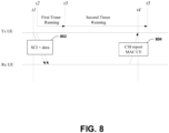
- FIG. 8 illustrates a timing diagram of an exemplary scenario associated with a Tx UE requesting a Rx UE to transmit a CSI report via sidelink, according to some embodiments.
- the Tx UE (a timeline of which is labeled "Tx UE" in FIG. 8 ) performs one or more sidelink transmissions 802 to a Rx UE (a timeline of which is labeled "Rx UE" in FIG. 8 ) for requesting a CSI report from the Rx UE.
- the one or more sidelink transmissions 802 may comprise a SCI (e.g., a SCI comprising and/or indicating a CSI report request) and/or data (e.g., sidelink data).
- SCI e.g., a SCI comprising and/or indicating a CSI report request
- data e.g., sidelink data
- the Tx UE may transmit the sidelink data with the SCI.
- at least one of the one or more sidelink transmissions 802 may be performed by the Tx UE at a time 11.
- the Rx UE may transmit a CSI report MAC CE 804 (e.g., a MAC CE comprising the CSI report) to the Tx UE in response to receiving the one or more sidelink transmissions 802 (and/or in response to receiving the SCI and/or the CSI report request).
- the Rx UE may transmit the CSI report MAC CE 804 using mode-1 sidelink grant and/or mode-2 sidelink grant.
- the CSI report MAC CE 804 may be transmitted by the Rx UE (and/or the CSI report MAC CE 804 may reach the Tx UE) at a time t4.
- the Tx UE in response to performing the one or more sidelink transmissions 802 (and/or in response to transmitting the SCI and/or in response to transmitting the sidelink data), the Tx UE may start or restart a first timer at a time t2.
- the time t2 is the same as the time 11. Alternatively and/or additionally, the time t2 may be after the time 11.
- the Tx UE may not monitor PSCCH (and/or the Tx UE may not monitor SCI) when the first timer is running.
- the Tx UE starts (and/or restarts) a second timer in response to expiry of the first timer.
- the Tx UE may be in active time and/or may monitor PSCCH (and/or monitor SCI from the Rx UE) when the second timer is running.
- the second timer may be running during the time t4. Accordingly, the Tx UE may monitor PSCCH (and/or monitor SCI from the Rx UE) at the time t4 and the Tx UE may receive the CSI report MAC CE 804.
- the second timer may run until the second timer expires at a time t5, after the time t4. Alternatively and/or additionally, the Tx UE may stop the second timer in response to receiving the CSI report MAC CE 804 at the time t4.
- FIG. 9 illustrates a timing diagram of an exemplary scenario associated with a Tx UE requesting a Rx UE to transmit a CSI report via sidelink, according to some embodiments.
- the Tx UE (a timeline of which is labeled "Tx UE" in FIG. 9 ) is configured with and/or operates using a sidelink DRX configuration associated with a sidelink DRX pattern (a timeline of which is labeled "Tx UE SL DRX Pattern" in FIG. 9 ).
- the Tx UE may monitor one or more sidelink channels when the Tx UE is in sidelink active time, such as during "On Duration" periods of the sidelink DRX pattern.
- the Tx UE may not monitor one or more sidelink channels when the Tx UE is not in sidelink active time, such as during "Inactive" periods of the sidelink DRX pattern.
- the Tx UE performs sidelink communication with a Rx UE (a timeline of which is labeled "Rx UE" in FIG. 9 ).
- the Tx UE transmits one or more transmissions 902 to the Rx UE, wherein the one or more transmissions 902 comprise a CSI report request and/or data (e.g., sidelink data). At least one of the one or more transmissions 902 may be performed by the Tx UE at a time 11.
- the Rx UE may generate a CSI report MAC CE 904 (e.g., a MAC CE comprising the CSI report) in response to receiving the one or more transmissions 902 (and/or in response to receiving the CSI report request) and/or the Rx UE may transmit the CSI report MAC CE 904 to the Tx UE.
- the Rx UE may transmit the CSI report MAC CE 904 using mode-1 sidelink grant and/or mode-2 sidelink grant.
- the CSI report MAC CE 904 may be transmitted by the Rx UE (and/or the CSI report MAC CE 904 may reach the Tx UE) at a time t2.
- the Tx UE in response to performing the one or more transmissions 902 (and/or in response to transmitting the CSI report request), the Tx UE may start or restart a timer at the time t1 (and/or after the time 11).
- the Tx UE may be in active time and/or the Tx UE may monitor the one or more sidelink channels when the timer is running. The timer may be running during the time t2. Accordingly, the Tx UE may monitor the one or more sidelink channels at the time t2 and the Tx UE may receive the CSI report MAC CE 904.
- the Tx UE may be in active time and/or may monitor the one or more sidelink channels at the time t2 based on the timer running at the time t2. In some examples, the timer may run until the timer expires at a time t3, after the time t2. Alternatively and/or additionally, the Tx UE may stop the timer in response to receiving the CSI report MAC CE 904 at the time t2.
- a third concept of the present disclosure is that a Rx UE may report a DRX configuration associated with a Tx UE to a base station.
- the base station may schedule, based on the DRX configuration, a sidelink grant for the Rx UE to perform one or more sidelink transmissions to the Tx UE when the Tx UE is in active time.
- the sidelink grant may be indicative of one or more sidelink resources for performance of the one or more sidelink transmissions, wherein the one or more sidelink resources are within active time of the Tx UE (e.g., the Tx UE is in active time during each resource of the one or more sidelink resources).
- the Rx UE may use at least one sidelink resource of the one or more sidelink resources to transmit a CSI report to the Tx UE (in response to the Rx UE receiving a CSI report request from the Tx UE, for example).
- a fourth concept of the present disclosure is that a Rx UE may use autonomous resource selection for transmitting a CSI report MAC CE to a Tx UE.
- the Rx UE may select one or more sidelink resources, for transmission of the CSI report MAC CE to the Tx UE, that are during active time of the Tx UE.
- the one or more sidelink resources may be selected based on a determination that the one or more sidelink resources are during the active time of the Tx UE, such that the CSI report MAC CE is transmitted to the Tx UE at a time in which the Tx UE is in active time.
- the one or more sidelink resources may be selected from sidelink resources at timings at which the Tx UE is in active time.
- the sidelink resources, from which the one or more sidelink resources are selected may not comprise sidelink resources at timings in which the Tx UE is not in active time.
- the Rx UE may not select the one or more sidelink resources from sidelink resources at timings at which the Tx UE is not in active time.
- the Rx UE may switch to autonomous resource selection for selecting the one or more sidelink resources for transmission of the CSI report MAC CE to the Tx UE.
- the Rx UE may switch to autonomous resource selection in response to receiving a CSI report request from the Tx UE and/or based on a determination that the Tx UE monitors based on a sidelink DRX configuration.
- the Tx UE may consider that the Tx UE is in active time (e.g., sidelink active time) when the timer (and/or the first timer and/or the second timer) is running.
- active time e.g., sidelink active time
- the Tx UE may monitor one or more sidelink control channels (e.g., PSCCH or Physical Sidelink Feedback Channel (PSFCH)) if the Tx UE is in active time (e.g., sidelink active time). For example, the Tx UE may monitor the one or more sidelink control channels during active time (e.g., sidelink active time) of the Tx UE.
- sidelink control channels e.g., PSCCH or Physical Sidelink Feedback Channel (PSFCH)
- the Tx UE may not monitor the one or more sidelink control channels, based on the timer, for one or more retransmissions (e.g., one or more possible retransmissions).
- the Tx UE may be performing unicast communication with the Rx UE.
- the Tx UE may be performing groupcast communication with the Rx UE.
- a sidelink-CSI (SL-CSI) report may be triggered for and/or at the Rx UE in response to the Rx UE receiving a SCI indicating a CSI report request.
- SL-CSI sidelink-CSI
- the Rx UE may generate a CSI report MAC CE (and/or transmit the MAC CE to the Tx UE) in response to the SL-CSI report being triggered.
- the one or more sidelink transmissions may comprise a SCI transmission.
- the one or more sidelink transmissions may comprise a sidelink data transmission.
- the one or more sidelink transmissions may not comprise (and/or may not be) a sidelink data transmission.
- embodiments disclosed herein such as embodiments described with respect to the first concept, the second concept, the third concept and the fourth concept, may be implemented independently and/or separately.
- a combination of embodiments described herein, such as embodiments described with respect to the first concept, the second concept, the third concept and/or the fourth concept may be implemented.
- a combination of embodiments described herein, such as embodiments described with respect to the first concept, the second concept, the third concept and/or the fourth concept may be implemented concurrently and/or simultaneously.
- Various techniques, embodiments, methods and/or alternatives of the present disclosure may be performed independently and/or separately from one another. Alternatively and/or additionally, various techniques, embodiments, methods and/or alternatives of the present disclosure may be combined and/or implemented using a single system. Alternatively and/or additionally, various techniques, embodiments, methods and/or alternatives of the present disclosure may be implemented concurrently and/or simultaneously.
- FIG. 10 is a flow chart 1000 according to one exemplary embodiment from the perspective of a first device.
- the first device transmits a SCI to a second device.
- the first device starts or restarts a timer in response to transmitting the SCI if the SCI indicates a CSI report request (e.g., a request for a CSI report) to the second device.
- the first device monitors a sidelink control channel when the timer is running.
- the first device receives a CSI report MAC CE from the second device.
- the first device does not start the timer if the SCI does not indicate a CSI report request.
- the first device stops the timer in response to receiving the CSI report MAC CE.
- the first device is in active time when the timer is running.
- the second device transmits the CSI report MAC CE to the first device in response to the SCI indicating the CSI report request.
- the device 300 includes a program code 312 stored in the memory 310.
- the CPU 308 could execute program code 312 to enable the first device (i) to transmit a SCI to a second device, (ii) to start or restart a timer in response to transmitting the SCI if the SCI indicates a CSI report request to the second device, (iii) to monitor a sidelink control channel when the timer is running, and (iv) to receive a CSI report MAC CE from the second device.
- the CPU 308 can execute the program code 312 to perform one, some and/or all of the above-described actions and steps and/or others described herein.
- FIG. 11 is a flow chart 1100 according to one exemplary embodiment from the perspective of a first device.
- the first device transmits a SCI to a second device, wherein the SCI indicates a CSI report request (e.g., a request for a CSI report) to the second device.
- the first device monitors a sidelink control channel in response to transmitting the SCI.
- the first device receives a CSI report MAC CE from the second device.
- the first device stops monitoring the sidelink control channel in response to receiving the CSI report MAC CE.
- the first device is in active time from a time at or after transmission of the SCI at least until the first device receives the CSI report MAC CE.
- the second device transmits the CSI report MAC CE to the first device in response to the SCI indicating the CSI report request.
- the device 300 includes a program code 312 stored in the memory 310.
- the CPU 308 could execute program code 312 to enable the first device (i) to transmit a SCI to a second device, wherein the SCI indicates a CSI report request (e.g., a request for a CSI report) to the second device, (ii) to monitor a sidelink control channel in response to transmitting the SCI, (iii) to receive a CSI report MAC CE from the second device, and (iv) to stop monitoring the sidelink control channel in response to receiving the CSI report MAC CE.
- the CPU 308 can execute the program code 312 to perform one, some and/or all of the above-described actions and steps and/or others described herein.
- FIG. 12 is a flow chart 1200 according to one exemplary embodiment from the perspective of a first device.
- the first device receives information associated with a second device, wherein the information indicates one or more timings at which the second device monitors sidelink control channel.
- the first device receives a SCI, indicating a CSI report request, from the second device.
- the first device transmits, based on the one or more timings, a CSI report MAC CE to the second device at a second timing.
- the second timing is associated with the one or more timings.
- the second timing is a timing of the one or more timings.
- the second timing is within a timing of the one or more timings.
- the CSI report MAC CE is not transmitted at a timing that is not included in and/or indicated by the one or more timings at which the second device monitors sidelink control channel.
- the second timing at which the first device transmits the CSI report MAC CE may be included in and/or indicated by the one or more timings at which the second device monitors sidelink control channel (e.g., the second timing may correspond to at least a portion of a timing of the one or more timings).
- the first device does not select a sidelink resource, for transmission of the CSI report MAC CE to the second device, that is associated with (e.g., within) a timing that is not included in and/or indicated by the one or more timings at which the second device monitors sidelink control channel.
- the first device may select a first sidelink resource, for transmission of the CSI report MAC CE to the second device, that is within a timing that is included in and/or indicated by the one or more timings at which the second device monitors sidelink control channel (e.g., the first sidelink resource may be within at least a portion of a timing of the one or more timings).
- the device 300 includes a program code 312 stored in the memory 310.
- the CPU 308 could execute program code 312 to enable the first device (i) to receive information associated with a second device, wherein the information indicates one or more timings at which the second device monitors sidelink control channel, (ii) to receive a SCI indicating a CSI report request from the second device, and (iii) to transmit, based on the one or more timings, a CSI report MAC CE to the second device at a second timing.
- the CPU 308 can execute the program code 312 to perform one, some and/or all of the above-described actions and steps and/or others described herein.
- the first device performs sidelink unicast communication with the second device.
- the first device performs sidelink groupcast communication with the second device.
- the sidelink control channel is PSCCH.
- the sidelink control channel is PSSCH.
- the sidelink control channel is PSFCH.
- the timer is an inactivity timer for DRX for sidelink.
- FIG. 13 is a flow chart 1300 according to one exemplary embodiment from the perspective of a first device configured to discontinuously monitor one or more sidelink control channels.
- the first device performs a first sidelink transmission to a second device.
- the first device starts or restarts a timer in response to the first sidelink transmission (e.g., in response to performing the first sidelink transmission).
- the first device monitors a first sidelink control channel, from at least the second device, when the timer is running.
- the first sidelink control channel may be associated with one or more devices comprising the second device. The first device may monitor the first sidelink control channel based on the timer.
- the first sidelink transmission is a SCI transmission indicating a CSI report request.
- the first sidelink transmission comprises a SCI transmission and a sidelink data transmission.
- the first sidelink transmission indicates a CSI report request.
- the first device may start or restart the timer based on the first sidelink transmission indicating the CSI report request. For example, the first device starts or restarts the timer in response to the first sidelink transmission indicating the CSI report request (e.g., in response to performing the first sidelink transmission which indicates the CSI report request).
- the first sidelink transmission indicates a CSI report request.
- the first device may start or restart the timer in response to the CSI report request and/or the first sidelink transmission.
- the first device may start or restart the timer in response to the CSI report request indicated by the first sidelink transmission (e.g., in response to performing the first sidelink transmission which indicates the CSI report request).
- the first device may start or restart the timer based on the CSI report request indicated by the first sidelink transmission (e.g., based on performing the first sidelink transmission which indicates the CSI report request).
- the first device performs a second sidelink transmission to the second device, wherein the second sidelink transmission does not indicate a CSI report request.
- the first device does not start or restart the timer in response to the second sidelink transmission.
- the first device may not start or restart the timer in response to the second sidelink transmission based on the second sidelink transmission not indicating a CSI report request.
- the first device stops the timer in response to receiving a CSI report MAC CE from the second device.
- the first device is in sidelink active time when the timer is running, wherein the first device monitors one or more sidelink control channels when the first device is in sidelink active time.
- the first sidelink transmission and/or a CSI report request indicated by the first sidelink transmission triggers the second device to transmit a CSI report MAC CE to the first device.
- the first sidelink control channel is monitored to receive (and/or acquire) one or more CSI reports from the second device.
- the second device triggers transmission of a CSI report MAC CE to the first device in response to the first sidelink transmission and/or the CSI report request (e.g., the second device may trigger transmission of the CSI Report MAC CE to the first device in response to receiving the first sidelink transmission and/or the CSI report request).
- the first device performs sidelink unicast communication with the second device.
- the sidelink control channel is PSCCH, PSSCH and/or PSFCH.
- the timer is an inactivity timer for DRX for sidelink.
- a time length of the timer is configured and/or pre-configured for a link between the first device and the second device.
- the first device and/or the second device associated with the link may be configured with the time length.
- the time length of the timer may be specified (e.g., specified to the first device performing sidelink communication and/or to the second device performing sidelink communication).
- the time length of the timer may be specified for the link between the first device and the second device.
- the time length of the timer may be based on a CSI report availability time (e.g., an availability time for CSI report).
- a CSI report availability time e.g., an availability time for CSI report.
- the time length may be determined and/or set based on the CSI report availability time.
- the time length of the timer being based on the CSI report availability time prevents reception of an out of date CSI report.
- the time length of the timer determined and/or set based on the CSI report availability time prevents reception of an out of date CSI report.
- the time length of the timer may be equal to or less than the CSI report availability time.
- the CSI report availability time is associated with (e.g., used for) preventing reception of an out of date CSI report (e.g., the CSI report availability time is used to set the time length of the timer to prevent reception of an out of date CSI report, such as a CSI report received after the timer expires).
- the CSI report availability time is configured and/or pre-configured for the link between the first device and the second device.
- the first device and/or the second device associated with the link may be configured with the CSI report availability time.
- the CSI report availability time may be specified (e.g., specified to the first device performing sidelink communication and/or to the second device performing sidelink communication).
- the CSI report availability time may be specified for the link between the first device and the second device.
- the device 300 includes a program code 312 stored in the memory 310.
- the CPU 308 could execute program code 312 to enable the first device (i) to perform a first sidelink transmission to a second device, (ii) to start or restart a timer in response to the first sidelink transmission (e.g., in response to performing the first sidelink transmission), and (iii) to monitor, when the timer is running, a first sidelink control channel from at least the second device.
- the CPU 308 can execute the program code 312 to perform one, some and/or all of the above-described actions and steps and/or others described herein.
- FIG. 14 is a flow chart 1400 according to one exemplary embodiment from the perspective of a first device configured to discontinuously monitor one or more sidelink control channels.
- the first device performs a first sidelink transmission to a second device, wherein the first sidelink transmission indicates a CSI report request (e.g., a request for a CSI report).
- a CSI report request e.g., a request for a CSI report.
- the first device in response to the first sidelink transmission and/or the CSI report request (e.g., in response to performing the first sidelink transmission indicating the CSI report request), stays in sidelink active time (and/or keeps operating in sidelink active time and/or continues operating in sidelink active time), for monitoring a first sidelink control channel from at least the second device, during a time window or a time interval of a CSI report availability time (e.g., an availability time for CSI report).
- the first device may be in sidelink active time and monitor the first sidelink control channel during the time window or the time interval.
- the first device may enter sidelink active time and/or the first device may keep (and/or continue) being in sidelink active time during the time window or the time interval.
- the first device may be in sidelink active time when the first device performs the first sidelink transmission indicating the CSI report request, and, in response to performing the first sidelink transmission indicating the CSI report request, the first device may stay in sidelink active time (and/or may keep operating in sidelink active time and/or continue operating in sidelink active time), for monitoring the first sidelink control channel, during the time window or the time interval.
- the first sidelink control channel may be associated with one or more devices comprising the second device.
- the first device starts or restarts a timer in response to the first sidelink transmission and/or the CSI report request (e.g., in response to performing the first sidelink transmission indicating the CSI report request).
- the first device stops the timer in response to receiving a CSI report MAC CE from the second device.
- the first device is in sidelink active time when the timer is running, wherein the first device monitors one or more sidelink control channels when the first device is in sidelink active time.
- the first sidelink transmission and/or the CSI report request triggers the second device to transmit a CSI report MAC CE to the first device.
- the first sidelink control channel is monitored to receive (and/or acquire) one or more CSI reports from the second device.
- the second device triggers transmission of a CSI report MAC CE to the first device in response to the first sidelink transmission and/or the CSI report request (e.g., the second device may trigger transmission of the CSI Report MAC CE to the first device in response to receiving the first sidelink transmission and/or the CSI report request).
- the timer is an inactivity timer for DRX for sidelink.
- a time length of the timer is configured and/or pre-configured for a link between the first device and the second device.
- the first device and/or the second device associated with the link may be configured with the time length.
- the time length of the timer may be specified (e.g., specified to the first device performing sidelink communication and/or to the second device performing sidelink communication).
- the time length of the timer may be specified for the link between the first device and the second device.
- the time length of the timer may be based on the CSI report availability time.
- the time length may be determined and/or set based on the CSI report availability time and/or a duration of the time window or the time interval.
- the time length of the timer being based on the CSI report availability time prevents reception of an out of date CSI report.
- the time length (determined and/or set based on the CSI report availability time and/or the duration of the time window or the time interval) prevents reception of an out of data CSI report.
- the CSI report availability time is associated with (e.g., used for) preventing reception of an out of date CSI report (e.g., the CSI report availability time is used to set the time length of the timer to prevent reception of an out of date CSI report, such as a CSI report received after the timer expires).
- the CSI report availability time is configured and/or pre-configured for the link between the first device and the second device.
- the first device and/or the second device associated with the link may be configured with the CSI report availability time.
- the CSI report availability time may be specified (e.g., specified to the first device performing sidelink communication and/or to the second device performing sidelink communication).
- the CSI report availability time may be specified for the link between the first device and the second device.
- a duration of the time window or the time interval may be equal to or less than the CSI report availability time.
- the device 300 includes a program code 312 stored in the memory 310.
- the CPU 308 could execute program code 312 to enable the first device (i) to perform a first sidelink transmission to a second device, wherein the first sidelink transmission indicates a CSI report request (e.g., a request for a CSI report), and (ii) in response to the first sidelink transmission and/or the CSI report request (e.g., in response to performing the first sidelink transmission indicating the CSI report request), to stay in active time, for monitoring a first sidelink control channel from at least the second device, during a time window or a time interval of a CSI report availability time (e.g., an availability time for CSI report).
- the CPU 308 can execute the program code 312 to perform one, some and/or all of the above-described actions and steps and/or others described herein.
- a communication device e.g., a device, a sidelink device, a UE, a base station, a network node, etc.
- the communication device may comprise a control circuit, a processor installed in the control circuit and/or a memory installed in the control circuit and coupled to the processor.
- the processor may be configured to execute a program code stored in the memory to perform method steps illustrated in FIGS. 10-14 .
- the processor may execute the program code to perform one, some and/or all of the above-described actions and steps and/or others described herein.
- a computer-readable medium may be provided.
- the computer-readable medium may be a non-transitory computer-readable medium.
- the computer-readable medium may comprise a flash memory device, a hard disk drive, a disc (e.g., a magnetic disc and/or an optical disc, such as at least one of a digital versatile disc (DVD), a compact disc (CD), etc.), and/or a memory semiconductor, such as at least one of static random access memory (SRAM), dynamic random access memory (DRAM), synchronous dynamic random access memory (SDRAM), etc.
- the computer-readable medium may comprise processor-executable instructions, that when executed cause performance of one, some and/or all method steps illustrated in FIGS. 10-14 , and/or one, some and/or all of the above-described actions and steps and/or others described herein.
- applying one or more of the techniques presented herein may result in one or more benefits including, but not limited to, increased efficiency of communication between devices (e.g., a first device and a second device performing sidelink communication).
- the increased efficiency may be a result of avoiding data loss and resource waste by enabling the first device to monitor a sidelink control channel and receive a CSI report from the second device, even if a time at which the CSI report is transmitted by the second device is outside sidelink active time of a sidelink DRX configuration with which the first device is configured.
- concurrent channels may be established based on pulse repetition frequencies. In some aspects, concurrent channels may be established based on pulse position or offsets. In some aspects, concurrent channels may be established based on time hopping sequences. In some aspects, concurrent channels may be established based on pulse repetition frequencies, pulse positions or offsets, and time hopping sequences.
- the various illustrative logical blocks, modules, and circuits described in connection with the aspects disclosed herein may be implemented within or performed by an integrated circuit ("IC"), an access terminal, or an access point.
- the IC may comprise a general purpose processor, a digital signal processor (DSP), an application specific integrated circuit (ASIC), a field programmable gate array (FPGA) or other programmable logic device, discrete gate or transistor logic, discrete hardware components, electrical components, optical components, mechanical components, or any combination thereof designed to perform the functions described herein, and may execute codes or instructions that reside within the IC, outside of the IC, or both.
- a general purpose processor may be a microprocessor, but in the alternative, the processor may be any conventional processor, controller, microcontroller, or state machine.
- a processor may also be implemented as a combination of computing devices, e.g., a combination of a DSP and a microprocessor, a plurality of microprocessors, one or more microprocessors in conjunction with a DSP core, or any other such configuration.
- a software module e.g., including executable instructions and related data
- other data may reside in a data memory such as RAM memory, flash memory, ROM memory, EPROM memory, EEPROM memory, registers, a hard disk, a removable disk, a CD-ROM, or any other form of computer-readable storage medium known in the art.
- a sample storage medium may be coupled to a machine such as, for example, a computer/processor (which may be referred to herein, for convenience, as a "processor") such the processor can read information (e.g., code) from and write information to the storage medium.
- a sample storage medium may be integral to the processor.
- the processor and the storage medium may reside in an ASIC.
- the ASIC may reside in user equipment.
- the processor and the storage medium may reside as discrete components in user equipment.
- any suitable computer-program product may comprise a computer-readable medium comprising codes relating to one or more of the aspects of the disclosure.
- a computer program product may comprise packaging materials.
Landscapes
- Engineering & Computer Science (AREA)
- Signal Processing (AREA)
- Computer Networks & Wireless Communication (AREA)
- Mobile Radio Communication Systems (AREA)
Claims (15)
- Verfahren einer ersten Vorrichtung, die eingerichtet ist, diskontinuierlich einen oder mehrere Sidelink-Steuerkanäle zu beobachten, wobei das Verfahren umfasst:Ausführen einer ersten Sidelink-Übertragung an eine zweite Vorrichtung zum Anfordern eines CSi-Reports von der zweiten Vorrichtung (1305);gekennzeichnet durchStarten oder erneutes Starten eines Zeitgebers durch die erste Vorrichtung als Reaktion auf die erste Sidelink-Übertragung (1310), undBeobachten eines ersten Sidelink-Steuerkanals, von mindestens der zweiten Vorrichtung, wenn der Zeitgeber läuft (1315).
- Verfahren gemäß Anspruch 1, wobei:
die erste Sidelink-Übertragung eine Sidelink-Steuerinformations-, im Folgenden auch als SCI bezeichnet, Übertragung ist, die eine Kanalzustandsinformation-, in Folgenden auch als CSI bezeichnet, Reportanforderung anzeigt. - Verfahren gemäß Anspruch 1 oder 2, wobei:
die erste Sidelink-Übertragung eine SCI-Übertragung und eine Sidelink-Datenübertragung umfasst. - Verfahren gemäß einem der Ansprüche 1 bis 3, wobei:die erste Sidelink-Übertragung eine CSI-Reportanforderung anzeigt; undmindestens eins von:Starten oder erneutes Starten des Zeitgebers als Reaktion darauf, dass die erste Sidelink-Übertragung durch ein Starten oder ein erneutes Starten des Zeitgebers basierend auf der CSI-Reportanforderung ausgeführt wird, die durch die erste Sidelink-Übertragung angezeigt wird; oderStarten oder erneutes Starten des Zeitgebers als Reaktion darauf, dass die erste Sidelink-Übertragung durch ein Starten oder ein erneutes Starten des Zeitgebers als Reaktion auf die CSI-Reportanforderung ausgeführt wird, die durch die erste Sidelink-Übertragung angezeigt wird.
- Verfahren einer ersten Vorrichtung, die eingerichtet ist, diskontinuierlich einen oder mehrere Sidelink-Steuerkanäle zu beobachten, wobei das Verfahren umfasst:Ausführen einer ersten Sidelink-Übertragung an eine zweite Vorrichtung, wobei die erste Sidelink-Übertragung eine Kanalzustandsinformation-, im Folgenden auch als CSI bezeichnet, Reportanforderung anzeigt (1405);gekennzeichnet durchals Reaktion darauf, dass die erste Sidelink-Übertragung die erste CSI-Reportanforderung anzeigt, Verbleiben in einer Sidelink-Aktivzeit zum Beobachten eines ersten Sidelink-Steuerkanals von mindestens der zweiten Vorrichtung während eines Zeitintervalls einer CSI-Reportverfügbarkeitszeit (1410); undBeenden des Verbleibens in der Sidelink-Aktivzeit als Reaktion darauf, dass ein CSI-Report, der mit der CSI-Reportanforderung verknüpft ist, empfangen wird.
- Verfahren gemäß Anspruch 5, umfassend:
Starten oder erneutes Starten eines Zeitgebers als Reaktion darauf, dass die erste Sidelink-Übertragung die CSI-Reportanforderung anzeigt. - Verfahren gemäß einem der Ansprüche 1 bis 4 und 6, umfassend:
Ausführen einer zweiten Sidelink-Übertragung an die zweite Vorrichtung, wobei die zweite Sidelink-Übertragung eine CSI-Reportanforderung nicht anzeigt, wobei basierend darauf, dass die zweite Sidelink-Übertragung eine CSI-Reportanforderung nicht anzeigt, die erste Vorrichtung nicht den Zeitgeber als Reaktion auf die zweite Sidelink-Übertragung startet oder erneut startet. - Verfahren gemäß einem der Ansprüche 1 bis 4, 6 und 7, umfassend:
Stoppen des Zeitgebers als Reaktion auf ein Empfangen eines CSI-Report-Medium-Access-Control-Steuerelements, im Folgenden auch als MAC-CE bezeichnet, von der zweiten Vorrichtung. - Verfahren gemäß einem der Ansprüche 1 bis 4 und 6 bis 8, wobei:die erste Vorrichtung in einer Sidelink-Aktivzeit ist, wenn der Zeitgeber läuft; unddie erste Vorrichtung einen oder mehrere Sidelink-Steuerkanäle beobachtet, wenn die erste Vorrichtung in einer Sidelink-Aktivzeit ist.
- Verfahren gemäß einem der Ansprüche 1 bis 4 und 6 bis 9, wobei:
eine Zeitdauer des Zeitgebers mindestens eins ist von bestimmt oder festgelegt basierend darauf, dass die CSI-Reportverfügbarkeitszeit einen Empfang eines veralteten CSi-Reports verhindert. - Verfahren gemäß einem der Ansprüche 1 bis 4 und 6 bis 10, wobei mindestens eins gilt von:eine/die Zeitdauer des Zeitgebers ist mindestens eins von spezifiziert für die erste Vorrichtung oder konfiguriert für eine Verbindung zwischen der ersten Vorrichtung und der zweiten Vorrichtung;der Zeitgeber ist ein Inaktivitätszeitgeber für einen diskontinuierlichen Empfang, im Folgenden auch als DRX bezeichnet, für einen Sidelink; oderdie Zeitdauer des Zeitgebers ist mindestens eins von bestimmt oder festgelegt basierend auf einer/der CSI-Reportverfügbarkeitszeit.
- Verfahren gemäß einem der Ansprüche 1 bis 11, wobei mindestens eins gilt von:die erste Sidelink-Übertragung, die die CSI-Reportanforderung anzeigt, löst aus, dass die zweite Vorrichtung ein CSI-Report-MAC-CE an die erste Vorrichtung sendet; oderein Beobachten des ersten Sidelink-Steuerkanals wird ausgeführt, um einen CSI-Report von der zweiten Vorrichtung zu empfangen.
- Verfahren gemäß einem der Ansprüche 1 bis 12, wobei:
der erste Sidelink-Steuerkanal mindestens einer ist von einem physikalischen Sidelink-Steuerkanal, im Folgenden auch als PSCCH bezeichnet, einem physikalischen Sidelink-Gemeinschaftskanal, im Folgenden auch als PSSCH bezeichnet, oder einem physikalischen Sidelink-Rückkopplungskanal, im Folgenden auch als PSFCH bezeichnet. - Verfahren gemäß einem der Ansprüche 1 bis 13, wobei mindestens eins gilt von:die CSi-Reportverfügbarkeitszeit ist mit einem Verhindern eines Empfangs eines veralteten CSi-Reports verknüpft; oderdie CSi-Reportverfügbarkeitszeit ist mindestens eins von spezifiziert für die erste Vorrichtung oder konfiguriert für die Verbindung zwischen der ersten Vorrichtung und der zweiten Vorrichtung.
- Erste Vorrichtung, die eingerichtet ist, einen oder mehrere Sidelink-Steuerkanäle diskontinuierlich zu beobachten, wobei die erste Vorrichtung aufweist:eine Steuerungsschaltung (306);einen Prozessor (308), der in der Steuerungsschaltung (306) installiert ist; undeinen Speicher (310), der in der Steuerungsschaltung (306) installiert und betriebsfähig mit dem Prozessor (308) verbunden ist, wobei der Prozessor (308) eingerichtet ist, einen Programm-Code (312), der in dem Speicher (310) gespeichert ist, auszuführen, um Operationen auszuführen,dadurch gekennzeichnet, dass die Operationen die in einem der vorstehenden Ansprüche definierten Verfahrensschritte umfassen.
Applications Claiming Priority (1)
| Application Number | Priority Date | Filing Date | Title |
|---|---|---|---|
| US202062963610P | 2020-01-21 | 2020-01-21 |
Publications (2)
| Publication Number | Publication Date |
|---|---|
| EP3855861A1 EP3855861A1 (de) | 2021-07-28 |
| EP3855861B1 true EP3855861B1 (de) | 2024-04-17 |
Family
ID=74191656
Family Applications (1)
| Application Number | Title | Priority Date | Filing Date |
|---|---|---|---|
| EP21152432.7A Active EP3855861B1 (de) | 2020-01-21 | 2021-01-20 | Verfahren und vorrichtung zur handhabung von kanalzustandsinformationsmeldung hinsichtlich des diskontinuierlichen sidelink-empfangs in einem drahtloskommunikationssystem |
Country Status (5)
| Country | Link |
|---|---|
| US (1) | US11553420B2 (de) |
| EP (1) | EP3855861B1 (de) |
| KR (1) | KR102547777B1 (de) |
| CN (1) | CN113225843B (de) |
| ES (1) | ES2983328T3 (de) |
Families Citing this family (26)
| Publication number | Priority date | Publication date | Assignee | Title |
|---|---|---|---|---|
| CN113260025B (zh) * | 2020-02-10 | 2023-04-14 | 大唐移动通信设备有限公司 | 一种非连续接收处理方法、终端、装置以及介质 |
| CA3167457A1 (en) | 2020-02-12 | 2021-08-19 | Idac Holdings, Inc. | Method and apparatus for performing simultaneous sidelink discontinuous (drx) and uplink drx in new radio (nr) vehicle to everything (v2x) |
| US11729832B2 (en) * | 2020-02-24 | 2023-08-15 | Qualcomm Incorporated | Random access channel message without a physical downlink control channel |
| CN113497688A (zh) * | 2020-04-02 | 2021-10-12 | 维沃移动通信有限公司 | 调度请求的配置方法、终端及网络设备 |
| WO2021206340A1 (ko) * | 2020-04-07 | 2021-10-14 | 주식회사 케이티 | 사이드링크 통신을 제어하는 방법 및 그 장치 |
| WO2021205627A1 (ja) * | 2020-04-09 | 2021-10-14 | 富士通株式会社 | 無線通信装置、無線通信システム及び電力制御方法 |
| CN115462161A (zh) * | 2020-04-10 | 2022-12-09 | Lg 电子株式会社 | 在nr v2x中确定sci上的ndi值的方法和装置 |
| CN115699908A (zh) * | 2020-06-12 | 2023-02-03 | 联想(北京)有限公司 | 用于侧链路drx操作的方法及设备 |
| WO2022019629A1 (ko) * | 2020-07-22 | 2022-01-27 | 삼성전자 주식회사 | 무선 통신 시스템에서 사이드링크 drx 운용에 필요한 사이드링크 자원을 처리하기 위한 장치 및 방법 |
| EP4152872B1 (de) * | 2020-08-06 | 2026-03-11 | Lg Electronics Inc. | Verfahren und vorrichtung zur durchführung einer sl-kommunikation auf basis von durch eine basisstation in nr v2x zugewiesenen ressourcen |
| US20220070964A1 (en) * | 2020-09-03 | 2022-03-03 | Qualcomm Incorporated | Sidelink feedback in discontinuous reception mode operation |
| WO2022061752A1 (zh) | 2020-09-25 | 2022-03-31 | Oppo广东移动通信有限公司 | 通信方法、装置及设备 |
| WO2022131781A1 (en) | 2020-12-15 | 2022-06-23 | Samsung Electronics Co., Ltd. | Method of handling active time for sl communication |
| EP4271054A4 (de) * | 2020-12-24 | 2024-11-13 | LG Electronics Inc. | Verfahren und vorrichtung zur durchführung eines sl-drx-betriebs in nr v2x |
| US11516775B2 (en) * | 2021-01-08 | 2022-11-29 | Qualcomm Incorporated | Probability-based utilization of sidelink resources |
| US12336043B2 (en) * | 2021-03-18 | 2025-06-17 | Qualcomm Incorporated | Sidelink DRX configuration for unicast |
| US20230284162A1 (en) * | 2021-03-30 | 2023-09-07 | Mitsubishi Electric Corporation | Communication system and receiver |
| WO2022205174A1 (zh) * | 2021-03-31 | 2022-10-06 | Oppo广东移动通信有限公司 | 一种控制定时器的方法及装置、终端设备 |
| US20220377831A1 (en) * | 2021-05-24 | 2022-11-24 | Qualcomm Incorporated | Timer operations for directional sidelink discontinuous reception |
| WO2023008823A1 (ko) * | 2021-07-28 | 2023-02-02 | 엘지전자 주식회사 | Nr v2x에서 sl csi 보고와 관련된 무선 통신을 수행하는 방법 및 장치 |
| CN115811717A (zh) * | 2021-09-16 | 2023-03-17 | 夏普株式会社 | 由用户设备执行的方法以及用户设备 |
| CN115884222B (zh) * | 2021-09-26 | 2025-11-25 | 邦克山科技有限责任公司 | 一种被用于无线通信的方法和设备 |
| WO2023050076A1 (en) * | 2021-09-28 | 2023-04-06 | Qualcomm Incorporated | Recovering procedure for inter user equipment coordination message request and response failure |
| KR102581243B1 (ko) | 2021-11-16 | 2023-09-25 | 엘지전자 주식회사 | Nr v2x에서 sl drx와 관련된 무선 통신을 수행하는 방법 및 장치 |
| KR20230135008A (ko) * | 2022-03-15 | 2023-09-22 | 현대자동차주식회사 | 비면허대역의 사이드링크 통신에서 csi 보고를 위한 방법 및 장치 |
| WO2023184437A1 (zh) * | 2022-03-31 | 2023-10-05 | 北京小米移动软件有限公司 | 信道状态信息csi报告的获取方法、装置及存储介质 |
Family Cites Families (16)
| Publication number | Priority date | Publication date | Assignee | Title |
|---|---|---|---|---|
| US10292100B2 (en) * | 2014-05-08 | 2019-05-14 | Telefonaktiebolaget Lm Ericsson (Publ) | Method and apparatus for indicating and adapting the activity state of a wireless device having device-to-device communication capabilities |
| WO2016064194A2 (ko) * | 2014-10-21 | 2016-04-28 | 엘지전자 주식회사 | 무선 통신 시스템에서 d2d 신호 송수신 방법 및 이를 위한 장치 |
| WO2017078783A1 (en) * | 2015-11-06 | 2017-05-11 | Intel Corporation | Methods and devices for communication via sidelink |
| US11197134B2 (en) * | 2016-04-02 | 2021-12-07 | Lg Electronics Inc. | Method and device for enhancing V2P communication in wireless communication system |
| WO2018064477A1 (en) * | 2016-09-30 | 2018-04-05 | Intel IP Corporation | Systems and methods for discontinuous reception in device-to-device communication |
| TWI658745B (zh) * | 2016-10-17 | 2019-05-01 | 華碩電腦股份有限公司 | 無線通訊系統中處置不連續接收(drx)操作的方法和設備 |
| EP3665849B1 (de) * | 2017-08-10 | 2024-05-01 | InterDigital Patent Holdings, Inc. | Verbesserte drx-verfahren für nr im verbundenen modus |
| KR102425402B1 (ko) * | 2017-09-28 | 2022-07-27 | 5쥐 아이피 홀딩스 엘엘씨 | 뉴 라디오에서 불연속 수신을 제어하기 위한 디바이스들 및 방법들 |
| US10834777B2 (en) | 2018-01-11 | 2020-11-10 | Ofinnon, LLC | Discontinuous reception and CSI |
| WO2019197025A1 (en) | 2018-04-11 | 2019-10-17 | Telefonaktiebolaget Lm Ericsson (Publ) | Technique for sidelink feedback transmissions |
| US11089625B2 (en) | 2018-05-25 | 2021-08-10 | Futurewei Technologies, Inc. | Protection for mode-3 V2X UEs in the ITS band |
| US11178565B2 (en) * | 2018-11-02 | 2021-11-16 | FG Innovation Company Limited | Sidelink measurement reporting in next generation wireless networks |
| EP3890246B1 (de) * | 2018-11-29 | 2025-06-11 | Beijing Xiaomi Mobile Software Co., Ltd. | Verfahren und vorrichtung zur rückkopplung von csi-messungen und speichermedium |
| US11864013B2 (en) * | 2019-08-13 | 2024-01-02 | Lg Electronics Inc. | Method and apparatus for transmitting or receiving channel state information in wireless communication system |
| KR20220045200A (ko) * | 2019-08-14 | 2022-04-12 | 아이디에이씨 홀딩스, 인크. | 뉴 라디오 사이드링크 채널 상태 정보 획득을 위한 장치 및 방법들 |
| EP4187967A4 (de) * | 2020-09-08 | 2024-01-24 | LG Electronics Inc. | Verfahren und vorrichtung für sidelink-drx-timer-basierten energiesparenden endgerät in nr v2x |
-
2021
- 2021-01-20 ES ES21152432T patent/ES2983328T3/es active Active
- 2021-01-20 KR KR1020210008093A patent/KR102547777B1/ko active Active
- 2021-01-20 CN CN202110073576.0A patent/CN113225843B/zh active Active
- 2021-01-20 EP EP21152432.7A patent/EP3855861B1/de active Active
- 2021-01-20 US US17/153,446 patent/US11553420B2/en active Active
Also Published As
| Publication number | Publication date |
|---|---|
| ES2983328T3 (es) | 2024-10-22 |
| US11553420B2 (en) | 2023-01-10 |
| CN113225843A (zh) | 2021-08-06 |
| EP3855861A1 (de) | 2021-07-28 |
| KR20210095069A (ko) | 2021-07-30 |
| KR102547777B1 (ko) | 2023-06-26 |
| US20210227464A1 (en) | 2021-07-22 |
| CN113225843B (zh) | 2024-05-07 |
Similar Documents
| Publication | Publication Date | Title |
|---|---|---|
| EP3855861B1 (de) | Verfahren und vorrichtung zur handhabung von kanalzustandsinformationsmeldung hinsichtlich des diskontinuierlichen sidelink-empfangs in einem drahtloskommunikationssystem | |
| EP3855862B1 (de) | Verfahren und vorrichtung zur behandlung einer logischen kanalpriorisierung bezüglich des diskontinuierlichen sidelink-empfangs in einem drahtlosen kommunikationssystem | |
| US11363571B2 (en) | Method and apparatus for handling retransmission indication for configured grant in sidelink in a wireless communication system | |
| KR102443862B1 (ko) | 무선 통신 시스템에서 주기적 송신에 관한 사이드링크 불연속 수신을 핸들링하기 위한 방법 및 장치 | |
| CN112788657B (zh) | 在侧链路中传送侧链路测量报告的方法和设备 | |
| CN115119268B (zh) | 处置用于侧链路通信的周期性侧链路资源的方法和设备 | |
| US11825297B2 (en) | Method and apparatus of handling control signaling for inter-user equipment (UE) coordination information in a wireless communication system | |
| US20230354302A1 (en) | Method and apparatus of scheduling request for sidelink communication in multiple carriers in a wireless communication system | |
| HK40038893B (en) | Method and apparatus for handling retransmission indication for configured grant in sidelink in a wireless communication system | |
| HK40038893A (en) | Method and apparatus for handling retransmission indication for configured grant in sidelink in a wireless communication system | |
| HK40051645B (en) | Method and apparatus for transmitting sidelink measurement report in sidelink in a wireless communication system | |
| HK40051645A (en) | Method and apparatus for transmitting sidelink measurement report in sidelink in a wireless communication system |
Legal Events
| Date | Code | Title | Description |
|---|---|---|---|
| PUAI | Public reference made under article 153(3) epc to a published international application that has entered the european phase |
Free format text: ORIGINAL CODE: 0009012 |
|
| STAA | Information on the status of an ep patent application or granted ep patent |
Free format text: STATUS: THE APPLICATION HAS BEEN PUBLISHED |
|
| AK | Designated contracting states |
Kind code of ref document: A1 Designated state(s): AL AT BE BG CH CY CZ DE DK EE ES FI FR GB GR HR HU IE IS IT LI LT LU LV MC MK MT NL NO PL PT RO RS SE SI SK SM TR |
|
| STAA | Information on the status of an ep patent application or granted ep patent |
Free format text: STATUS: REQUEST FOR EXAMINATION WAS MADE |
|
| 17P | Request for examination filed |
Effective date: 20210920 |
|
| RBV | Designated contracting states (corrected) |
Designated state(s): AL AT BE BG CH CY CZ DE DK EE ES FI FR GB GR HR HU IE IS IT LI LT LU LV MC MK MT NL NO PL PT RO RS SE SI SK SM TR |
|
| GRAP | Despatch of communication of intention to grant a patent |
Free format text: ORIGINAL CODE: EPIDOSNIGR1 |
|
| STAA | Information on the status of an ep patent application or granted ep patent |
Free format text: STATUS: GRANT OF PATENT IS INTENDED |
|
| RIC1 | Information provided on ipc code assigned before grant |
Ipc: H04W 76/28 20180101ALN20230417BHEP Ipc: H04W 76/14 20180101AFI20230417BHEP |
|
| RIC1 | Information provided on ipc code assigned before grant |
Ipc: H04W 76/28 20180101ALN20230424BHEP Ipc: H04W 76/14 20180101AFI20230424BHEP |
|
| INTG | Intention to grant announced |
Effective date: 20230510 |
|
| RAP3 | Party data changed (applicant data changed or rights of an application transferred) |
Owner name: ASUSTEK COMPUTER INC. |
|
| GRAJ | Information related to disapproval of communication of intention to grant by the applicant or resumption of examination proceedings by the epo deleted |
Free format text: ORIGINAL CODE: EPIDOSDIGR1 |
|
| STAA | Information on the status of an ep patent application or granted ep patent |
Free format text: STATUS: REQUEST FOR EXAMINATION WAS MADE |
|
| GRAP | Despatch of communication of intention to grant a patent |
Free format text: ORIGINAL CODE: EPIDOSNIGR1 |
|
| STAA | Information on the status of an ep patent application or granted ep patent |
Free format text: STATUS: GRANT OF PATENT IS INTENDED |
|
| INTC | Intention to grant announced (deleted) | ||
| RIC1 | Information provided on ipc code assigned before grant |
Ipc: H04W 76/28 20180101ALN20230801BHEP Ipc: H04W 76/14 20180101AFI20230801BHEP |
|
| INTG | Intention to grant announced |
Effective date: 20230814 |
|
| GRAJ | Information related to disapproval of communication of intention to grant by the applicant or resumption of examination proceedings by the epo deleted |
Free format text: ORIGINAL CODE: EPIDOSDIGR1 |
|
| STAA | Information on the status of an ep patent application or granted ep patent |
Free format text: STATUS: REQUEST FOR EXAMINATION WAS MADE |
|
| GRAP | Despatch of communication of intention to grant a patent |
Free format text: ORIGINAL CODE: EPIDOSNIGR1 |
|
| STAA | Information on the status of an ep patent application or granted ep patent |
Free format text: STATUS: GRANT OF PATENT IS INTENDED |
|
| INTC | Intention to grant announced (deleted) | ||
| RIC1 | Information provided on ipc code assigned before grant |
Ipc: H04W 76/28 20180101ALN20231130BHEP Ipc: H04W 76/14 20180101AFI20231130BHEP |
|
| INTG | Intention to grant announced |
Effective date: 20240102 |
|
| GRAS | Grant fee paid |
Free format text: ORIGINAL CODE: EPIDOSNIGR3 |
|
| GRAA | (expected) grant |
Free format text: ORIGINAL CODE: 0009210 |
|
| STAA | Information on the status of an ep patent application or granted ep patent |
Free format text: STATUS: THE PATENT HAS BEEN GRANTED |
|
| AK | Designated contracting states |
Kind code of ref document: B1 Designated state(s): AL AT BE BG CH CY CZ DE DK EE ES FI FR GB GR HR HU IE IS IT LI LT LU LV MC MK MT NL NO PL PT RO RS SE SI SK SM TR |
|
| P01 | Opt-out of the competence of the unified patent court (upc) registered |
Effective date: 20240311 |
|
| REG | Reference to a national code |
Ref country code: GB Ref legal event code: FG4D |
|
| RIN1 | Information on inventor provided before grant (corrected) |
Inventor name: LI, MING-CHE Inventor name: HUANG, CHUN-WEI Inventor name: KUNG, YI-HSUAN |
|
| REG | Reference to a national code |
Ref country code: CH Ref legal event code: EP |
|
| REG | Reference to a national code |
Ref country code: DE Ref legal event code: R096 Ref document number: 602021011758 Country of ref document: DE |
|
| REG | Reference to a national code |
Ref country code: IE Ref legal event code: FG4D |
|
| REG | Reference to a national code |
Ref country code: NL Ref legal event code: FP |
|
| REG | Reference to a national code |
Ref country code: LT Ref legal event code: MG9D |
|
| REG | Reference to a national code |
Ref country code: AT Ref legal event code: MK05 Ref document number: 1678468 Country of ref document: AT Kind code of ref document: T Effective date: 20240417 |
|
| PG25 | Lapsed in a contracting state [announced via postgrant information from national office to epo] |
Ref country code: IS Free format text: LAPSE BECAUSE OF FAILURE TO SUBMIT A TRANSLATION OF THE DESCRIPTION OR TO PAY THE FEE WITHIN THE PRESCRIBED TIME-LIMIT Effective date: 20240817 |
|
| PG25 | Lapsed in a contracting state [announced via postgrant information from national office to epo] |
Ref country code: BG Free format text: LAPSE BECAUSE OF FAILURE TO SUBMIT A TRANSLATION OF THE DESCRIPTION OR TO PAY THE FEE WITHIN THE PRESCRIBED TIME-LIMIT Effective date: 20240417 |
|
| PG25 | Lapsed in a contracting state [announced via postgrant information from national office to epo] |
Ref country code: HR Free format text: LAPSE BECAUSE OF FAILURE TO SUBMIT A TRANSLATION OF THE DESCRIPTION OR TO PAY THE FEE WITHIN THE PRESCRIBED TIME-LIMIT Effective date: 20240417 Ref country code: FI Free format text: LAPSE BECAUSE OF FAILURE TO SUBMIT A TRANSLATION OF THE DESCRIPTION OR TO PAY THE FEE WITHIN THE PRESCRIBED TIME-LIMIT Effective date: 20240417 |
|
| PG25 | Lapsed in a contracting state [announced via postgrant information from national office to epo] |
Ref country code: GR Free format text: LAPSE BECAUSE OF FAILURE TO SUBMIT A TRANSLATION OF THE DESCRIPTION OR TO PAY THE FEE WITHIN THE PRESCRIBED TIME-LIMIT Effective date: 20240718 |
|
| PG25 | Lapsed in a contracting state [announced via postgrant information from national office to epo] |
Ref country code: PT Free format text: LAPSE BECAUSE OF FAILURE TO SUBMIT A TRANSLATION OF THE DESCRIPTION OR TO PAY THE FEE WITHIN THE PRESCRIBED TIME-LIMIT Effective date: 20240819 |
|
| REG | Reference to a national code |
Ref country code: ES Ref legal event code: FG2A Ref document number: 2983328 Country of ref document: ES Kind code of ref document: T3 Effective date: 20241022 |
|
| PG25 | Lapsed in a contracting state [announced via postgrant information from national office to epo] |
Ref country code: AT Free format text: LAPSE BECAUSE OF FAILURE TO SUBMIT A TRANSLATION OF THE DESCRIPTION OR TO PAY THE FEE WITHIN THE PRESCRIBED TIME-LIMIT Effective date: 20240417 |
|
| PG25 | Lapsed in a contracting state [announced via postgrant information from national office to epo] |
Ref country code: PL Free format text: LAPSE BECAUSE OF FAILURE TO SUBMIT A TRANSLATION OF THE DESCRIPTION OR TO PAY THE FEE WITHIN THE PRESCRIBED TIME-LIMIT Effective date: 20240417 |
|
| PG25 | Lapsed in a contracting state [announced via postgrant information from national office to epo] |
Ref country code: LV Free format text: LAPSE BECAUSE OF FAILURE TO SUBMIT A TRANSLATION OF THE DESCRIPTION OR TO PAY THE FEE WITHIN THE PRESCRIBED TIME-LIMIT Effective date: 20240417 |
|
| PG25 | Lapsed in a contracting state [announced via postgrant information from national office to epo] |
Ref country code: PT Free format text: LAPSE BECAUSE OF FAILURE TO SUBMIT A TRANSLATION OF THE DESCRIPTION OR TO PAY THE FEE WITHIN THE PRESCRIBED TIME-LIMIT Effective date: 20240819 Ref country code: PL Free format text: LAPSE BECAUSE OF FAILURE TO SUBMIT A TRANSLATION OF THE DESCRIPTION OR TO PAY THE FEE WITHIN THE PRESCRIBED TIME-LIMIT Effective date: 20240417 Ref country code: NO Free format text: LAPSE BECAUSE OF FAILURE TO SUBMIT A TRANSLATION OF THE DESCRIPTION OR TO PAY THE FEE WITHIN THE PRESCRIBED TIME-LIMIT Effective date: 20240717 Ref country code: LV Free format text: LAPSE BECAUSE OF FAILURE TO SUBMIT A TRANSLATION OF THE DESCRIPTION OR TO PAY THE FEE WITHIN THE PRESCRIBED TIME-LIMIT Effective date: 20240417 Ref country code: IS Free format text: LAPSE BECAUSE OF FAILURE TO SUBMIT A TRANSLATION OF THE DESCRIPTION OR TO PAY THE FEE WITHIN THE PRESCRIBED TIME-LIMIT Effective date: 20240817 Ref country code: HR Free format text: LAPSE BECAUSE OF FAILURE TO SUBMIT A TRANSLATION OF THE DESCRIPTION OR TO PAY THE FEE WITHIN THE PRESCRIBED TIME-LIMIT Effective date: 20240417 Ref country code: GR Free format text: LAPSE BECAUSE OF FAILURE TO SUBMIT A TRANSLATION OF THE DESCRIPTION OR TO PAY THE FEE WITHIN THE PRESCRIBED TIME-LIMIT Effective date: 20240718 Ref country code: FI Free format text: LAPSE BECAUSE OF FAILURE TO SUBMIT A TRANSLATION OF THE DESCRIPTION OR TO PAY THE FEE WITHIN THE PRESCRIBED TIME-LIMIT Effective date: 20240417 Ref country code: BG Free format text: LAPSE BECAUSE OF FAILURE TO SUBMIT A TRANSLATION OF THE DESCRIPTION OR TO PAY THE FEE WITHIN THE PRESCRIBED TIME-LIMIT Effective date: 20240417 Ref country code: AT Free format text: LAPSE BECAUSE OF FAILURE TO SUBMIT A TRANSLATION OF THE DESCRIPTION OR TO PAY THE FEE WITHIN THE PRESCRIBED TIME-LIMIT Effective date: 20240417 Ref country code: RS Free format text: LAPSE BECAUSE OF FAILURE TO SUBMIT A TRANSLATION OF THE DESCRIPTION OR TO PAY THE FEE WITHIN THE PRESCRIBED TIME-LIMIT Effective date: 20240717 |
|
| PG25 | Lapsed in a contracting state [announced via postgrant information from national office to epo] |
Ref country code: DK Free format text: LAPSE BECAUSE OF FAILURE TO SUBMIT A TRANSLATION OF THE DESCRIPTION OR TO PAY THE FEE WITHIN THE PRESCRIBED TIME-LIMIT Effective date: 20240417 |
|
| REG | Reference to a national code |
Ref country code: DE Ref legal event code: R097 Ref document number: 602021011758 Country of ref document: DE |
|
| PG25 | Lapsed in a contracting state [announced via postgrant information from national office to epo] |
Ref country code: EE Free format text: LAPSE BECAUSE OF FAILURE TO SUBMIT A TRANSLATION OF THE DESCRIPTION OR TO PAY THE FEE WITHIN THE PRESCRIBED TIME-LIMIT Effective date: 20240417 |
|
| PG25 | Lapsed in a contracting state [announced via postgrant information from national office to epo] |
Ref country code: CZ Free format text: LAPSE BECAUSE OF FAILURE TO SUBMIT A TRANSLATION OF THE DESCRIPTION OR TO PAY THE FEE WITHIN THE PRESCRIBED TIME-LIMIT Effective date: 20240417 |
|
| PG25 | Lapsed in a contracting state [announced via postgrant information from national office to epo] |
Ref country code: SK Free format text: LAPSE BECAUSE OF FAILURE TO SUBMIT A TRANSLATION OF THE DESCRIPTION OR TO PAY THE FEE WITHIN THE PRESCRIBED TIME-LIMIT Effective date: 20240417 Ref country code: RO Free format text: LAPSE BECAUSE OF FAILURE TO SUBMIT A TRANSLATION OF THE DESCRIPTION OR TO PAY THE FEE WITHIN THE PRESCRIBED TIME-LIMIT Effective date: 20240417 |
|
| PG25 | Lapsed in a contracting state [announced via postgrant information from national office to epo] |
Ref country code: SM Free format text: LAPSE BECAUSE OF FAILURE TO SUBMIT A TRANSLATION OF THE DESCRIPTION OR TO PAY THE FEE WITHIN THE PRESCRIBED TIME-LIMIT Effective date: 20240417 |
|
| PG25 | Lapsed in a contracting state [announced via postgrant information from national office to epo] |
Ref country code: SM Free format text: LAPSE BECAUSE OF FAILURE TO SUBMIT A TRANSLATION OF THE DESCRIPTION OR TO PAY THE FEE WITHIN THE PRESCRIBED TIME-LIMIT Effective date: 20240417 Ref country code: SK Free format text: LAPSE BECAUSE OF FAILURE TO SUBMIT A TRANSLATION OF THE DESCRIPTION OR TO PAY THE FEE WITHIN THE PRESCRIBED TIME-LIMIT Effective date: 20240417 Ref country code: RO Free format text: LAPSE BECAUSE OF FAILURE TO SUBMIT A TRANSLATION OF THE DESCRIPTION OR TO PAY THE FEE WITHIN THE PRESCRIBED TIME-LIMIT Effective date: 20240417 Ref country code: EE Free format text: LAPSE BECAUSE OF FAILURE TO SUBMIT A TRANSLATION OF THE DESCRIPTION OR TO PAY THE FEE WITHIN THE PRESCRIBED TIME-LIMIT Effective date: 20240417 Ref country code: DK Free format text: LAPSE BECAUSE OF FAILURE TO SUBMIT A TRANSLATION OF THE DESCRIPTION OR TO PAY THE FEE WITHIN THE PRESCRIBED TIME-LIMIT Effective date: 20240417 Ref country code: CZ Free format text: LAPSE BECAUSE OF FAILURE TO SUBMIT A TRANSLATION OF THE DESCRIPTION OR TO PAY THE FEE WITHIN THE PRESCRIBED TIME-LIMIT Effective date: 20240417 |
|
| PLBE | No opposition filed within time limit |
Free format text: ORIGINAL CODE: 0009261 |
|
| STAA | Information on the status of an ep patent application or granted ep patent |
Free format text: STATUS: NO OPPOSITION FILED WITHIN TIME LIMIT |
|
| 26N | No opposition filed |
Effective date: 20250120 |
|
| PG25 | Lapsed in a contracting state [announced via postgrant information from national office to epo] |
Ref country code: SI Free format text: LAPSE BECAUSE OF FAILURE TO SUBMIT A TRANSLATION OF THE DESCRIPTION OR TO PAY THE FEE WITHIN THE PRESCRIBED TIME-LIMIT Effective date: 20240417 |
|
| REG | Reference to a national code |
Ref country code: CH Ref legal event code: PL |
|
| PG25 | Lapsed in a contracting state [announced via postgrant information from national office to epo] |
Ref country code: SE Free format text: LAPSE BECAUSE OF FAILURE TO SUBMIT A TRANSLATION OF THE DESCRIPTION OR TO PAY THE FEE WITHIN THE PRESCRIBED TIME-LIMIT Effective date: 20240417 |
|
| PG25 | Lapsed in a contracting state [announced via postgrant information from national office to epo] |
Ref country code: MC Free format text: LAPSE BECAUSE OF FAILURE TO SUBMIT A TRANSLATION OF THE DESCRIPTION OR TO PAY THE FEE WITHIN THE PRESCRIBED TIME-LIMIT Effective date: 20240417 Ref country code: LU Free format text: LAPSE BECAUSE OF NON-PAYMENT OF DUE FEES Effective date: 20250120 |
|
| PG25 | Lapsed in a contracting state [announced via postgrant information from national office to epo] |
Ref country code: BE Free format text: LAPSE BECAUSE OF NON-PAYMENT OF DUE FEES Effective date: 20250131 |
|
| PG25 | Lapsed in a contracting state [announced via postgrant information from national office to epo] |
Ref country code: CH Free format text: LAPSE BECAUSE OF NON-PAYMENT OF DUE FEES Effective date: 20250131 |
|
| REG | Reference to a national code |
Ref country code: BE Ref legal event code: MM Effective date: 20250131 |
|
| PGFP | Annual fee paid to national office [announced via postgrant information from national office to epo] |
Ref country code: NL Payment date: 20251003 Year of fee payment: 6 |
|
| PGFP | Annual fee paid to national office [announced via postgrant information from national office to epo] |
Ref country code: GB Payment date: 20251103 Year of fee payment: 6 |
|
| PGFP | Annual fee paid to national office [announced via postgrant information from national office to epo] |
Ref country code: FR Payment date: 20251016 Year of fee payment: 6 |
|
| PG25 | Lapsed in a contracting state [announced via postgrant information from national office to epo] |
Ref country code: IE Free format text: LAPSE BECAUSE OF NON-PAYMENT OF DUE FEES Effective date: 20250120 |
|
| PGFP | Annual fee paid to national office [announced via postgrant information from national office to epo] |
Ref country code: ES Payment date: 20260203 Year of fee payment: 6 |
|
| PGFP | Annual fee paid to national office [announced via postgrant information from national office to epo] |
Ref country code: DE Payment date: 20251023 Year of fee payment: 6 |
|
| PGFP | Annual fee paid to national office [announced via postgrant information from national office to epo] |
Ref country code: IT Payment date: 20251006 Year of fee payment: 6 |