EP3856314B1 - Valve à fuite intentionnelle ainsi que système de tubes respiratoires - Google Patents
Valve à fuite intentionnelle ainsi que système de tubes respiratoires Download PDFInfo
- Publication number
- EP3856314B1 EP3856314B1 EP19702059.7A EP19702059A EP3856314B1 EP 3856314 B1 EP3856314 B1 EP 3856314B1 EP 19702059 A EP19702059 A EP 19702059A EP 3856314 B1 EP3856314 B1 EP 3856314B1
- Authority
- EP
- European Patent Office
- Prior art keywords
- housing
- leakage
- leakage valve
- housing part
- connection piece
- Prior art date
- Legal status (The legal status is an assumption and is not a legal conclusion. Google has not performed a legal analysis and makes no representation as to the accuracy of the status listed.)
- Active
Links
Images

Classifications
-
- A—HUMAN NECESSITIES
- A61—MEDICAL OR VETERINARY SCIENCE; HYGIENE
- A61M—DEVICES FOR INTRODUCING MEDIA INTO, OR ONTO, THE BODY; DEVICES FOR TRANSDUCING BODY MEDIA OR FOR TAKING MEDIA FROM THE BODY; DEVICES FOR PRODUCING OR ENDING SLEEP OR STUPOR
- A61M16/00—Devices for influencing the respiratory system of patients by gas treatment, e.g. ventilators; Tracheal tubes
- A61M16/08—Bellows; Connecting tubes ; Water traps; Patient circuits
- A61M16/0816—Joints or connectors
- A61M16/0825—Joints or connectors with ball-sockets
-
- A—HUMAN NECESSITIES
- A61—MEDICAL OR VETERINARY SCIENCE; HYGIENE
- A61M—DEVICES FOR INTRODUCING MEDIA INTO, OR ONTO, THE BODY; DEVICES FOR TRANSDUCING BODY MEDIA OR FOR TAKING MEDIA FROM THE BODY; DEVICES FOR PRODUCING OR ENDING SLEEP OR STUPOR
- A61M16/00—Devices for influencing the respiratory system of patients by gas treatment, e.g. ventilators; Tracheal tubes
- A61M16/08—Bellows; Connecting tubes ; Water traps; Patient circuits
- A61M16/0816—Joints or connectors
-
- A—HUMAN NECESSITIES
- A61—MEDICAL OR VETERINARY SCIENCE; HYGIENE
- A61M—DEVICES FOR INTRODUCING MEDIA INTO, OR ONTO, THE BODY; DEVICES FOR TRANSDUCING BODY MEDIA OR FOR TAKING MEDIA FROM THE BODY; DEVICES FOR PRODUCING OR ENDING SLEEP OR STUPOR
- A61M16/00—Devices for influencing the respiratory system of patients by gas treatment, e.g. ventilators; Tracheal tubes
- A61M16/20—Valves specially adapted to medical respiratory devices
- A61M16/208—Non-controlled one-way valves, e.g. exhalation, check, pop-off non-rebreathing valves
-
- A—HUMAN NECESSITIES
- A61—MEDICAL OR VETERINARY SCIENCE; HYGIENE
- A61M—DEVICES FOR INTRODUCING MEDIA INTO, OR ONTO, THE BODY; DEVICES FOR TRANSDUCING BODY MEDIA OR FOR TAKING MEDIA FROM THE BODY; DEVICES FOR PRODUCING OR ENDING SLEEP OR STUPOR
- A61M16/00—Devices for influencing the respiratory system of patients by gas treatment, e.g. ventilators; Tracheal tubes
- A61M16/08—Bellows; Connecting tubes ; Water traps; Patient circuits
-
- A—HUMAN NECESSITIES
- A61—MEDICAL OR VETERINARY SCIENCE; HYGIENE
- A61M—DEVICES FOR INTRODUCING MEDIA INTO, OR ONTO, THE BODY; DEVICES FOR TRANSDUCING BODY MEDIA OR FOR TAKING MEDIA FROM THE BODY; DEVICES FOR PRODUCING OR ENDING SLEEP OR STUPOR
- A61M16/00—Devices for influencing the respiratory system of patients by gas treatment, e.g. ventilators; Tracheal tubes
- A61M16/10—Preparation of respiratory gases or vapours
- A61M16/1075—Preparation of respiratory gases or vapours by influencing the temperature
- A61M16/1095—Preparation of respiratory gases or vapours by influencing the temperature in the connecting tubes
-
- A—HUMAN NECESSITIES
- A61—MEDICAL OR VETERINARY SCIENCE; HYGIENE
- A61M—DEVICES FOR INTRODUCING MEDIA INTO, OR ONTO, THE BODY; DEVICES FOR TRANSDUCING BODY MEDIA OR FOR TAKING MEDIA FROM THE BODY; DEVICES FOR PRODUCING OR ENDING SLEEP OR STUPOR
- A61M16/00—Devices for influencing the respiratory system of patients by gas treatment, e.g. ventilators; Tracheal tubes
- A61M16/10—Preparation of respiratory gases or vapours
- A61M16/14—Preparation of respiratory gases or vapours by mixing different fluids, one of them being in a liquid phase
- A61M16/16—Devices to humidify the respiration air
-
- A—HUMAN NECESSITIES
- A61—MEDICAL OR VETERINARY SCIENCE; HYGIENE
- A61M—DEVICES FOR INTRODUCING MEDIA INTO, OR ONTO, THE BODY; DEVICES FOR TRANSDUCING BODY MEDIA OR FOR TAKING MEDIA FROM THE BODY; DEVICES FOR PRODUCING OR ENDING SLEEP OR STUPOR
- A61M2202/00—Special media to be introduced, removed or treated
- A61M2202/02—Gases
- A61M2202/0225—Carbon oxides, e.g. Carbon dioxide
-
- A—HUMAN NECESSITIES
- A61—MEDICAL OR VETERINARY SCIENCE; HYGIENE
- A61M—DEVICES FOR INTRODUCING MEDIA INTO, OR ONTO, THE BODY; DEVICES FOR TRANSDUCING BODY MEDIA OR FOR TAKING MEDIA FROM THE BODY; DEVICES FOR PRODUCING OR ENDING SLEEP OR STUPOR
- A61M2205/00—General characteristics of the apparatus
- A61M2205/15—Detection of leaks
-
- A—HUMAN NECESSITIES
- A61—MEDICAL OR VETERINARY SCIENCE; HYGIENE
- A61M—DEVICES FOR INTRODUCING MEDIA INTO, OR ONTO, THE BODY; DEVICES FOR TRANSDUCING BODY MEDIA OR FOR TAKING MEDIA FROM THE BODY; DEVICES FOR PRODUCING OR ENDING SLEEP OR STUPOR
- A61M2205/00—General characteristics of the apparatus
- A61M2205/33—Controlling, regulating or measuring
- A61M2205/3331—Pressure; Flow
- A61M2205/3337—Controlling, regulating pressure or flow by means of a valve by-passing a pump
-
- A—HUMAN NECESSITIES
- A61—MEDICAL OR VETERINARY SCIENCE; HYGIENE
- A61M—DEVICES FOR INTRODUCING MEDIA INTO, OR ONTO, THE BODY; DEVICES FOR TRANSDUCING BODY MEDIA OR FOR TAKING MEDIA FROM THE BODY; DEVICES FOR PRODUCING OR ENDING SLEEP OR STUPOR
- A61M2205/00—General characteristics of the apparatus
- A61M2205/58—Means for facilitating use, e.g. by people with impaired vision
- A61M2205/586—Ergonomic details therefor, e.g. specific ergonomics for left or right-handed users
Definitions
- the present invention relates to a leakage valve according to the preamble of claim 1 and a breathing tube system according to claim 10.
- Leakage valves are used in what is known as leakage ventilation.
- the patient to be ventilated is provided with an amount of ventilation gas from a ventilator which is greater than the amount of ventilation gas consumed by the patient when breathing.
- the remainder of this ventilation gas volume provided by the ventilator leaves the ventilation circuit via the leakage valve.
- the ventilator has a precisely defined delivery rate of ventilation gas. This flow rate can be adapted to the relevant patient-dependent consumption quantities (e.g. ventilation of an adult or an infant) on the device side.
- Leak ventilation ventilators are usually precisely matched to the amount of leakage determined by the leakage valve. If there are fluctuations in the amount of leakage, these are not recorded and therefore lead to an undesirable impairment of the ventilation, which is of particular importance in the ventilation of newborns.
- a leakage valve according to the preamble of claim 1 is from EP 2 428 243 B1 famous.
- the two housing parts have a mutual gradation and passage openings in the area of the radially outwardly projecting housing area.
- the two housing parts that snap together should be connected to one another by a clamp connection to avoid twisting.
- a leakage valve which also consists of an outer part and an inner part that can be latched therewith.
- the inner part has spring tabs that act on the front end of the outer part.
- the outer part is spaced apart from the inner part to form a circumferential gap-like throttle chamber and has three narrow and one wide elevation on its wide end face, with the elevations together with the inner part allowing breathing air containing CO 2 to flow out of the throttle chamber in certain areas.
- a plurality of passage openings for an additional passage of air from the inside of the leakage valve into the throttle chamber can be provided in the inner part at a distance from a housing area projecting radially outwards.
- Inner part and outer part should be rotatable against each other. The problem with this design is that mechanical impairment of the leakage valve can lead to significant fluctuations in the amount of leakage.
- a respiratory mask in which a mask base body is connected to an exhalation element via a coupling element, the coupling element delimiting an outflow channel together with the exhalation element.
- the exhalation element is introduced in regions into a holding socket of the coupling element.
- a maximum depth of insertion is dictated by outer webs that run substantially parallel to a longitudinal axis of the exhalation element along an exterior side of the exhalation element.
- the exhalation element also has a plurality of radially extending connecting webs along its circumference, between which outflow openings are provided. The outside of the connecting webs run slightly inwards. The outflow openings are located above the outer webs.
- the exhalation element is fixed within the coupling element by locking elements, each of which engages behind an associated shoulder with a detent. A play between support studs and exhalation member may facilitate easy rotation of the exhalation member within the mounting post.
- the EP 1 138 340 A2 relates to a device for discharging at least partially used breathing gas from a breathing gas line system.
- the device comprises a first connection section and a second connection section as well as a discharge device for discharging a partial flow of respiratory gas, the discharge device being formed by at least one channel which is at least partially delimited by the wall of an elastomeric body.
- the channels are located in the area of a radially outwardly protruding bead.
- a rotary sleeve device is provided for rotatably coupling the connection sections.
- a plurality of radially flexible snap-in tongue elements can be provided, which can be brought into engagement detachably with a second connection element designed like a tubular socket.
- the DE 10 2007 052 898 B3 discloses a device for discharging respiratory gas with an outer part and an inner part which has a cylindrical sliding surface.
- the inner part is rotatably mounted within the outer part via a connecting member.
- An annular outflow gap for respiratory gas is formed between the connecting element and the outer part.
- the outflow gap is formed by spacer elements between the connecting element and the outer part.
- the spacer elements are designed in such a way that the connecting element is secured against twisting relative to the outer part.
- the spacer elements have latching tongues that can be connected to the outer part.
- the leak valve includes a tubular body defining a flow path for delivering gas during respiratory therapy, the tubular body having body orifices formed in the wall which direct gas from the flow path through its wall.
- a sleeve is rotatable about an axis relative to the tubular body, the sleeve substantially defining body openings in the body encloses.
- the sleeve also has sleeve openings that are positionable to overlap with the body openings.
- a tubular adjustment ring substantially encloses the socket openings in the socket, the adjustment ring having an adjustment ring opening formed therein.
- the adjustment ring opening is positionable to overlap with the socket openings and the body openings, wherein a rotary coupling between the tubular body, the socket and the adjustment ring facilitates an adjustable configuration of one or more properties of a leakage path, which is achieved by positioning the overlap of the adjustment ring opening with at least one of the sleeve openings and at least one of the body openings to permit leakage during respiratory therapy.
- the object of the present invention is to provide a generic leakage valve by means of which fluctuations in the amount of leakage can be effectively avoided.
- the leakage valve according to the invention is characterized by a construction that is favorable in terms of production technology.
- the rotatability of the two housing parts to one another is expediently achieved in that, when the two housing parts are in the latched state, there is a clearance between the axially running latching lugs and the axially running inner wall of the first connecting piece.
- a gap clearance can be provided between the nose of the latching tabs on the front side and the front end of the first connecting piece.
- a gap clearance can be provided between the axially running outer wall of the curved wall areas and the axially running inner wall of the first connecting piece.
- the dimension of the gap (gap play) for the rotatability of the two housing parts is essentially 0.08 mm to 0.12 mm (i.e. based on the diameter 0.04 mm to 0.06 mm per side), preferably 0.09 mm to 0.11 mm (i.e. in relation to the diameter 0.045 mm to 0.055 mm per side).
- the aforesaid design means that the two housing parts can rotate relative to one another without the application of force, thereby avoiding the occurrence of mechanical stresses on the leakage valve during use and the amount of leakage is not subject to any fluctuations.
- the housing part having the through-openings has no gradation, apart from the radially outwardly projecting webs.
- the webs protrude beyond the curved wall area to the outside, it is possible to use the webs at the same time as supports for the first housing part.
- the first housing part expediently rests on the webs of the second housing part, preferably butt-jointly.
- the first housing part expediently has a circumferential stepped surface which rests on the upper side on the webs when the two housing parts are in the latched state.
- the first and/or second housing part are preferably designed in one piece.
- the second housing part can have a ring-like extension or a ring-like projection in the area of the extended housing area. which extends radially outwards and, together with the inner wall of the first housing part, forms the leakage channel leading to the outside.
- the ring-like extension is provided with a peripheral recess on its underside, the overall mechanical stability of the second housing part is additionally reinforced.
- the present invention further relates to a breathing tube system for use in leak ventilation, the breathing tube system comprising a preferably heatable breathing tube and a leakage valve according to claims 1 to 9.
- the breathing tube system is further characterized in that a connecting sleeve for connecting the breathing tube to the leakage valve and/or to a functional part is provided at at least one end, preferably at both ends of the breathing tube.
- the leakage valve is expediently located between the connecting sleeve and a ventilation aid positioned on the patient.
- the leakage valve is expediently located between the connecting socket and a connector with probe connection means.
- the reference number 15 is a breathing device located on the patient, such as a breathing mask, which is provided with a connecting piece (not shown) and is connected to a leakage valve 1 according to the invention.
- a connector 24 with a connection for a probe can be connected to the leakage valve 1, for example.
- a breathing tube 13 which, if required, can contain a heating wire which is intended to keep the breathing gas within the breathing tube at a specific temperature. However, a heating wire does not necessarily have to be present.
- the breathing tube 13 has a connecting sleeve 18, 19 at each of its ends.
- the breathing tube 13 is connected via a further connector 23 Connection for a probe with a humidification chamber 16 of a humidifier 14 in connection. Specially conditioned ventilation gas is kept ready in the humidification chamber 16 .
- the humidification chamber 16 is connected to a fan 22 via a connecting tube 20 and a connector 21 . In order to ensure a certain moisture content of the respiration gas located inside the humidification chamber 16 , this is connected to a water reservoir 17 .
- the conditioned ventilation gas stored in the humidifier chamber 16 is conveyed to the patient via the ventilation tube 13 due to the overpressure generated by the ventilator 22 .
- the ventilation gas is inhaled by the patient and exhaled again through the ventilation mask.
- the patient is supplied with an amount of ventilation gas which is greater than the amount consumed by the patient when breathing.
- the remainder of the ventilation gas volume provided by the ventilation gas leaves the ventilation circuit via leakage valve 1.
- the ventilation gas flows through the inner lumen of the leakage valve and immediately washes out any remaining used air from the leakage valve.
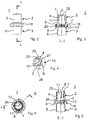
- the leakage valve 1 comprises a first round housing part 2 and a second round housing part 3 , a first connecting piece 4 being provided on the first housing part 2 and a second connecting piece 5 being provided on the second housing part 3 .
- the leakage valve 1 is connected to the ventilation device 15 , for example a ventilation mask, with the connecting piece 4 .
- the second connecting piece 5 is used to connect the leakage valve 1 to the connector 24 with probe connection means or directly to the breathing tube 13 .
- the second housing part 3 forms the inner lumen of the leakage valve 1, the first housing part 2 being arranged on the outside of the second housing part 3 and latched in the axial direction via a snap connection.
- the first housing part 2 is pushed over the cylindrical area of the second housing part 3 .
- the cylindrical portion has curved wall portions 26 between which slots 11 are provided. These slots 11 form latching tabs 6 with lugs 7 on the upper side, which latch with the upper end face of the first housing part 2 and thus fix the latter in an axial holding position.
- annular leakage channel 9 Between the inner wall of the first housing part 2 and the outside of the second housing part 3 there is an annular leakage channel 9 in the area of the widened housing area 10, through which ventilation gas can escape to the outside.
- webs 12 directed radially outwards are provided on the second housing part 3 along the circumference of the second housing part 3 , which delimit passage openings 8 . Ventilation gas can get from the inner lumen of the leakage valve into the interior of the widened area 10 via the passage openings 8 and from there into the circumferential leakage channel 9 .
- the through-openings 8 have a large surface area, since they are limited only by the webs 12 running radially.
- a ring-like extension 27 is provided, the outer peripheral face of which together with the inner wall of the first housing part 2 in the area of the housing extension 10 forms the leakage channel 9 .
- the first housing part 2 has a step surface 25 that preferably runs all the way around, which rests on the upper side on the webs 12 when the two housing parts 2, 3 are in the latched state.
- the ring-like extension 27 has a peripheral recess 28 on its underside, which leads to a mechanical reinforcement of the second housing part 3 or the ring-like extension 27 . This mechanical stability prevents the leakage channel 9 from changing under mechanical stress and thus impairing the leakage flow.
- the ability to rotate the two housing parts 2, 3 relative to one another in the latched state, which can be performed without exertion of force, is achieved by providing a slight gap between the axially running outer wall of the first housing part 2 in the region of the latching tabs 6 and the inner wall of the first connecting piece 4.
- a corresponding clearance can also be provided between the nose 7 of the locking tabs 6 and the end of the first connecting piece 4 .
- a slight gap play can also be provided between the axially running outer wall, the curved wall areas 26 of the first housing part 2 and the axially running inner wall of the first connecting piece 4 .
- the dimension of the gap (gap play) for the rotatability of the two housing parts is essentially 0.08 mm to 0.12 mm (i.e. based on the diameter 0.04 mm to 0.06 mm per side), preferably 0.09 mm to 0.11 mm (i.e. in relation to the diameter 0.045 mm to 0.055 mm per side).
- the clearance in relation to the diameter is 0.10 mm, i.e. 0.05 mm per side.
- figure 5 shows the leakage valve 1 in a view from above. One can see the two opposing latching tabs 6 with the upper end-side lugs 7 of the first housing part 2 which engage over the upper end of the second housing part 3 .
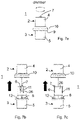
- the Figure 7b and 7c show the leakage valve in an exploded view.
- the respective area of the through-openings 8 provided along the circumference, through which respiratory gas from the inner lumen of the leakage valve 1 into the annular space 29 and from there into the annular leakage channel 9 (cf. e.g 3 ) can reach.
- the construction according to the invention also makes it possible to produce the housing parts 2 and 3 in one piece from plastic in a simple manner in an injection molding process.
Landscapes
- Health & Medical Sciences (AREA)
- Pulmonology (AREA)
- Life Sciences & Earth Sciences (AREA)
- Animal Behavior & Ethology (AREA)
- Anesthesiology (AREA)
- Biomedical Technology (AREA)
- Heart & Thoracic Surgery (AREA)
- Hematology (AREA)
- Emergency Medicine (AREA)
- Engineering & Computer Science (AREA)
- General Health & Medical Sciences (AREA)
- Public Health (AREA)
- Veterinary Medicine (AREA)
- Infusion, Injection, And Reservoir Apparatuses (AREA)
- Taps Or Cocks (AREA)
- Respiratory Apparatuses And Protective Means (AREA)
Claims (13)
- Valve à fuite intentionnelle (1) destinée à être utilisée dans un système de respiration avec
un boîtier de valve constitué d'une première (2) et d'une deuxième partie de boîtier (3), de préférence de plastique, les deux parties de boîtier (2, 3) formant un canal de fluide dont la section transversale est de préférence circulaire, le boîtier de valve comportant :une première tubulure de raccordement (4) sur la première partie de boîtier (2),une deuxième tubulure de raccordement (5) sur la deuxième partie de boîtier (3) ainsi qu'une région de boîtier faisant saillie radialement vers l'extérieur (10) entre les deux tubulures de raccordement (4, 5),au moins une ouverture de passage (8) disposée approximativement à la hauteur de la région de boîtier faisant saillie radialement vers l'extérieur (10) et permettant une sortie du fluide hors du canal de fluide sous la forme d'un courant de fuite,un canal de fuite (9) également disposé à la hauteur de la région de boîtier faisant saillie radialement vers l'extérieur (10), s'étendant au moins le long d'une partie de la circonférence du boîtier de valve, de préférence le long de la totalité de celle-ci, formé de préférence par les deux parties de boîtier (2, 3) pour la sortie du courant de fuite hors de la valve à fuite intentionnelle (1),un mécanisme d'encliquetage, au moyen duquel les deux parties de boîtier (2, 3) peuvent être reliées entre elles,dans laquelle, en tant que mécanisme d'encliquetage, il est prévu au moins une, de préférence une pluralité de patte(s) d'encliquetage (6) incurvée(s) de manière correspondante au rayon intérieur de la tubulure de raccordement (4 ou 5) avec un nez côté frontal (7), laquelle/lesquelles s'étend(-ent) le long de la tubulure de raccordement (4 ou 5) en s'appliquant sur le côté intérieur de celle-ci dans l'état de l'encliquetage tout en engageant le côté frontal extérieur de la tubulure de raccordement (4 ou 5) avec leur nez (7) et en assurant un encliquetage axial, et il est prévu des régions de paroi incurvées (26) de manière correspondante au rayon intérieur de la tubulure de raccordement (4 ou 5) entre les pattes d'encliquetage (6), lesquelles sont adjacentes à la surface intérieure de la tubulure de raccordement (4 ou 5), dans laquelle les deux parties de boîtier (2, 3) peuvent être tournées l'une vers l'autre dans l'état encliqueté,sur la deuxième partie de boîtier (3), il est prévu plusieurs âmes (12) s'étendant radialement le long de la circonférence, entre lesquelles sont prévues les ouvertures de passage (8) ou lesquelles délimitent les ouvertures de passage (8) latéralement,les âmes (12) font saillie au-delà du côté extérieur des régions de paroi incurvées (26), etentre la paroi intérieure de la région de boîtier élargie (10) et l'extrémité côté extérieur de l'âme (12) respective subsiste un espace annulaire circonférentiel (29). - Valve à fuite intentionnelle selon la revendication 1, caractérisée en ce que dans l'état encliqueté des deux parties de boîtier (2, 3), il est prévu un jeu de fente entre la paroi extérieure s'étendant axialement des pattes d'encliquetage (6) et la paroi intérieure s'étendant axialement de la première tubulure de raccordement (4).
- Valve à fuite intentionnelle selon la revendication 1 ou 2, caractérisée en ce que dans l'état encliqueté des deux parties de boîtier (2, 3), il est prévu un jeu de fente entre le nez côté frontal (7) des pattes d'encliquetage (6) et l'extrémité côté frontal de la première tubulure de raccordement (4),
- Valve à fuite intentionnelle selon les revendications précédentes, caractérisée en ce que dans l'état encliqueté des deux parties de boîtier (2, 3), il est prévu un jeu de fente entre la paroi extérieure s'étendant axialement des régions de paroi incurvées (26) et la paroi intérieure s'étendant axialement de la première tubulure de raccordement (4).
- Valve à fuite intentionnelle selon les revendications 1 à 4, caractérisée en ce que dans l'état encliqueté des deux parties de boîtier (2, 3), la première partie de boîtier (2) s'appuie sur les âmes (12).
- Valve à fuite intentionnelle selon les revendications 1 à 5, caractérisée en ce que la première partie de boîtier (2) présente une surface étagée circonférentielle (25), laquelle s'appuie sur les âmes (12) côté supérieur dans l'état encliqueté des deux parties de boîtier (2, 3).
- Valve à fuite intentionnelle selon les revendications précédentes, caractérisée en ce que la première (2) et/ou la deuxième partie de boîtier (3) sont réalisées en une seule pièce.
- Valve à fuite intentionnelle selon les revendications précédentes, caractérisée en ce que la deuxième partie de boîtier (3) présente un élargissement du genre anneau (27) dans la région de la région de boîtier élargie (10).
- Valve à fuite intentionnelle selon la revendication 8, caractérisée en ce que l'élargissement du genre anneau (27) est pourvu d'un évidement circonférentiel (28) sur son côté inférieur.
- Système de tube respiratoire destiné à être utilisé dans le cadre d'une ventilation à fuite, comportant un tube respiratoire (13) de préférence chauffable ainsi qu'une valve à fuite intentionnelle (1) selon les revendications précédentes.
- Système de tube respiratoire selon la revendication 10, caractérisé en ce qu'à au moins une extrémité, de préférence aux deux extrémités du tube respiratoire (13), il est prévu un manchon de raccordement (18, 19) permettant de raccorder le tube respiratoire (13) à la valve à fuite intentionnelle (1) et/ou une partie fonctionnelle.
- Système de tube respiratoire selon les revendications 10 à 11, caractérisé en ce que la valve à fuite intentionnelle (1) se trouve entre le manchon de raccordement (18) et un dispositif respiratoire (15) positionné sur le patient.
- Système de tube respiratoire selon les revendications 10 à 12, caractérisé en ce que la valve à fuite intentionnelle (1) se trouve entre le manchon de raccordement (18) et un connecteur (24) comprenant un moyen de raccordement de sonde.
Applications Claiming Priority (1)
| Application Number | Priority Date | Filing Date | Title |
|---|---|---|---|
| PCT/EP2019/051781 WO2020151827A1 (fr) | 2019-01-24 | 2019-01-24 | Valve à fuite intentionnelle ainsi que système de tubes respiratoires |
Publications (2)
| Publication Number | Publication Date |
|---|---|
| EP3856314A1 EP3856314A1 (fr) | 2021-08-04 |
| EP3856314B1 true EP3856314B1 (fr) | 2022-12-28 |
Family
ID=65237032
Family Applications (1)
| Application Number | Title | Priority Date | Filing Date |
|---|---|---|---|
| EP19702059.7A Active EP3856314B1 (fr) | 2019-01-24 | 2019-01-24 | Valve à fuite intentionnelle ainsi que système de tubes respiratoires |
Country Status (4)
| Country | Link |
|---|---|
| US (1) | US12569641B2 (fr) |
| EP (1) | EP3856314B1 (fr) |
| JP (1) | JP7257532B2 (fr) |
| WO (1) | WO2020151827A1 (fr) |
Family Cites Families (11)
| Publication number | Priority date | Publication date | Assignee | Title |
|---|---|---|---|---|
| AUPP855099A0 (en) * | 1999-02-09 | 1999-03-04 | Resmed Limited | Gas delivery connection assembly |
| US5937851A (en) * | 1997-02-27 | 1999-08-17 | Respironics, Inc. | Swivel device utilizing bearing clearance to allow carbon dioxide laden exhaust |
| DE19840760C2 (de) * | 1998-09-07 | 2000-07-20 | Map Medizintechnik Gmbh | Schalldämpfer für Beatmungsvorrichtung |
| DE10014178C2 (de) | 2000-03-23 | 2003-04-10 | Map Medizin Technologie Gmbh | Vorrichtung zur Ableitung von Atemgas |
| DE10158066A1 (de) | 2001-11-27 | 2003-06-05 | Weinmann G Geraete Med | Beatmungsmaske |
| DE102007052898B3 (de) | 2007-11-07 | 2009-04-30 | Dräger Medical AG & Co. KG | Vorrichtung zur Ableitung von Atemgas |
| DE102010045299A1 (de) | 2010-09-14 | 2012-03-15 | Wilamed Gmbh | Leckagenventil |
| US9993608B2 (en) * | 2012-05-02 | 2018-06-12 | Fisher & Paykel Healthcare Limited | Respiratory humidifier communication systems and methods |
| WO2013188845A1 (fr) * | 2012-06-15 | 2013-12-19 | The Regents Of The University Of California | Système et méthodes destinés à l'isolement de poumons et à la ventilation unipulmonaire |
| EP3209357B1 (fr) | 2014-10-24 | 2019-07-31 | Koninklijke Philips N.V. | Système permettant de réguler les fuites |
| US10315002B2 (en) | 2015-03-24 | 2019-06-11 | Ventec Life Systems, Inc. | Ventilator with integrated oxygen production |
-
2019
- 2019-01-24 US US17/424,746 patent/US12569641B2/en active Active
- 2019-01-24 JP JP2021543319A patent/JP7257532B2/ja active Active
- 2019-01-24 WO PCT/EP2019/051781 patent/WO2020151827A1/fr not_active Ceased
- 2019-01-24 EP EP19702059.7A patent/EP3856314B1/fr active Active
Also Published As
| Publication number | Publication date |
|---|---|
| WO2020151827A1 (fr) | 2020-07-30 |
| US20220105306A1 (en) | 2022-04-07 |
| JP7257532B2 (ja) | 2023-04-13 |
| EP3856314A1 (fr) | 2021-08-04 |
| JP2022518799A (ja) | 2022-03-16 |
| US12569641B2 (en) | 2026-03-10 |
Similar Documents
| Publication | Publication Date | Title |
|---|---|---|
| EP0276024B1 (fr) | Système de connexion pour conduits de gaz munies d'éléments de raccordement enfichables pour des appareils respiratoires ou d'anesthésie | |
| DE102007052898B3 (de) | Vorrichtung zur Ableitung von Atemgas | |
| EP0985430B1 (fr) | Silencieux pour dispositifs respiratoires et inhalateurs | |
| EP0054714A2 (fr) | Système de connection munis d'élements de raccordement enfichables pour des appareils respiratoires ou d'anesthésie | |
| EP3624883B1 (fr) | Soupape d'expiration d'un dispositif respiratoire avec résistance à l'écoulement minimisant les bruits | |
| DE3819237A1 (de) | Endotrachealtubus | |
| DE2947363A1 (de) | Exhalationsventil | |
| DE102012006396A1 (de) | Tracheostomietubus | |
| DE69533070T2 (de) | Beatmungsvorrichtungen mit kontrolliertem zugang | |
| DE102005041717B4 (de) | Atemmaske mit Strömungsleitstrukturen | |
| DE3626790C2 (fr) | ||
| EP2805748B1 (fr) | Masque respiratoire doté d'une soupape de respiration de secours | |
| DE19757703C5 (de) | Beatmungsvorrichtung | |
| EP1776153B1 (fr) | Dispositif pour evacuer du gaz respiratoire de l'interieur d'un masque respiratoire, ainsi qu'ensemble masque respiratoire comprenant ce dispositif | |
| DE10134725A1 (de) | Vorrichtung zur Filterung von Atemluft | |
| DE29721766U1 (de) | Anschlußstück für die Atemgasversorgung eines Patienten | |
| EP3856314B1 (fr) | Valve à fuite intentionnelle ainsi que système de tubes respiratoires | |
| DE202017102703U1 (de) | Gehäuseaufbau eines Durchflusssensors | |
| EP3144026B1 (fr) | Masque respiratoire en plusieurs partie, element d'obturation du nez associe et combinaison associee d'un element de raccord de tuyau et un element de couplage | |
| DE102020131994B4 (de) | Druckausgleichselement | |
| DE102012004359B4 (de) | Kugelgelenk mit zwei Kugelsegmenten | |
| DE202020106578U1 (de) | Vorrichtung zum Koppeln einer Beatmungsmaske oder eines nicht-invasiven Systems mit einem Luft-Sauerstoff-Mischer zur High-Flow-Oxygen-Therapie | |
| DE60108787T2 (de) | Anordnung zur künstlichen beatmung der lungen | |
| EP2603129B1 (fr) | Tubulure de connexion pour aspirateur | |
| EP2428243B1 (fr) | Soupape anti-fuites |
Legal Events
| Date | Code | Title | Description |
|---|---|---|---|
| STAA | Information on the status of an ep patent application or granted ep patent |
Free format text: STATUS: UNKNOWN |
|
| STAA | Information on the status of an ep patent application or granted ep patent |
Free format text: STATUS: THE INTERNATIONAL PUBLICATION HAS BEEN MADE |
|
| PUAI | Public reference made under article 153(3) epc to a published international application that has entered the european phase |
Free format text: ORIGINAL CODE: 0009012 |
|
| STAA | Information on the status of an ep patent application or granted ep patent |
Free format text: STATUS: REQUEST FOR EXAMINATION WAS MADE |
|
| 17P | Request for examination filed |
Effective date: 20210426 |
|
| AK | Designated contracting states |
Kind code of ref document: A1 Designated state(s): AL AT BE BG CH CY CZ DE DK EE ES FI FR GB GR HR HU IE IS IT LI LT LU LV MC MK MT NL NO PL PT RO RS SE SI SK SM TR |
|
| GRAP | Despatch of communication of intention to grant a patent |
Free format text: ORIGINAL CODE: EPIDOSNIGR1 |
|
| STAA | Information on the status of an ep patent application or granted ep patent |
Free format text: STATUS: GRANT OF PATENT IS INTENDED |
|
| GRAJ | Information related to disapproval of communication of intention to grant by the applicant or resumption of examination proceedings by the epo deleted |
Free format text: ORIGINAL CODE: EPIDOSDIGR1 |
|
| STAA | Information on the status of an ep patent application or granted ep patent |
Free format text: STATUS: REQUEST FOR EXAMINATION WAS MADE |
|
| DAV | Request for validation of the european patent (deleted) | ||
| DAX | Request for extension of the european patent (deleted) | ||
| GRAJ | Information related to disapproval of communication of intention to grant by the applicant or resumption of examination proceedings by the epo deleted |
Free format text: ORIGINAL CODE: EPIDOSDIGR1 |
|
| GRAP | Despatch of communication of intention to grant a patent |
Free format text: ORIGINAL CODE: EPIDOSNIGR1 |
|
| GRAP | Despatch of communication of intention to grant a patent |
Free format text: ORIGINAL CODE: EPIDOSNIGR1 |
|
| STAA | Information on the status of an ep patent application or granted ep patent |
Free format text: STATUS: GRANT OF PATENT IS INTENDED |
|
| INTG | Intention to grant announced |
Effective date: 20220420 |
|
| INTC | Intention to grant announced (deleted) | ||
| INTG | Intention to grant announced |
Effective date: 20220512 |
|
| GRAJ | Information related to disapproval of communication of intention to grant by the applicant or resumption of examination proceedings by the epo deleted |
Free format text: ORIGINAL CODE: EPIDOSDIGR1 |
|
| STAA | Information on the status of an ep patent application or granted ep patent |
Free format text: STATUS: REQUEST FOR EXAMINATION WAS MADE |
|
| GRAS | Grant fee paid |
Free format text: ORIGINAL CODE: EPIDOSNIGR3 |
|
| STAA | Information on the status of an ep patent application or granted ep patent |
Free format text: STATUS: GRANT OF PATENT IS INTENDED |
|
| GRAP | Despatch of communication of intention to grant a patent |
Free format text: ORIGINAL CODE: EPIDOSNIGR1 |
|
| INTC | Intention to grant announced (deleted) | ||
| RAP1 | Party data changed (applicant data changed or rights of an application transferred) |
Owner name: LOEWENSTEIN MEDICAL TECHNOLOGY S.A. |
|
| INTG | Intention to grant announced |
Effective date: 20220927 |
|
| GRAA | (expected) grant |
Free format text: ORIGINAL CODE: 0009210 |
|
| STAA | Information on the status of an ep patent application or granted ep patent |
Free format text: STATUS: THE PATENT HAS BEEN GRANTED |
|
| AK | Designated contracting states |
Kind code of ref document: B1 Designated state(s): AL AT BE BG CH CY CZ DE DK EE ES FI FR GB GR HR HU IE IS IT LI LT LU LV MC MK MT NL NO PL PT RO RS SE SI SK SM TR |
|
| REG | Reference to a national code |
Ref country code: GB Ref legal event code: FG4D Free format text: NOT ENGLISH |
|
| REG | Reference to a national code |
Ref country code: CH Ref legal event code: EP |
|
| REG | Reference to a national code |
Ref country code: DE Ref legal event code: R096 Ref document number: 502019006633 Country of ref document: DE |
|
| REG | Reference to a national code |
Ref country code: AT Ref legal event code: REF Ref document number: 1540071 Country of ref document: AT Kind code of ref document: T Effective date: 20230115 |
|
| REG | Reference to a national code |
Ref country code: IE Ref legal event code: FG4D Free format text: LANGUAGE OF EP DOCUMENT: GERMAN |
|
| REG | Reference to a national code |
Ref country code: LT Ref legal event code: MG9D |
|
| PG25 | Lapsed in a contracting state [announced via postgrant information from national office to epo] |
Ref country code: SE Free format text: LAPSE BECAUSE OF FAILURE TO SUBMIT A TRANSLATION OF THE DESCRIPTION OR TO PAY THE FEE WITHIN THE PRESCRIBED TIME-LIMIT Effective date: 20221228 Ref country code: NO Free format text: LAPSE BECAUSE OF FAILURE TO SUBMIT A TRANSLATION OF THE DESCRIPTION OR TO PAY THE FEE WITHIN THE PRESCRIBED TIME-LIMIT Effective date: 20230328 Ref country code: LT Free format text: LAPSE BECAUSE OF FAILURE TO SUBMIT A TRANSLATION OF THE DESCRIPTION OR TO PAY THE FEE WITHIN THE PRESCRIBED TIME-LIMIT Effective date: 20221228 Ref country code: FI Free format text: LAPSE BECAUSE OF FAILURE TO SUBMIT A TRANSLATION OF THE DESCRIPTION OR TO PAY THE FEE WITHIN THE PRESCRIBED TIME-LIMIT Effective date: 20221228 |
|
| REG | Reference to a national code |
Ref country code: NL Ref legal event code: MP Effective date: 20221228 |
|
| PG25 | Lapsed in a contracting state [announced via postgrant information from national office to epo] |
Ref country code: RS Free format text: LAPSE BECAUSE OF FAILURE TO SUBMIT A TRANSLATION OF THE DESCRIPTION OR TO PAY THE FEE WITHIN THE PRESCRIBED TIME-LIMIT Effective date: 20221228 Ref country code: LV Free format text: LAPSE BECAUSE OF FAILURE TO SUBMIT A TRANSLATION OF THE DESCRIPTION OR TO PAY THE FEE WITHIN THE PRESCRIBED TIME-LIMIT Effective date: 20221228 Ref country code: HR Free format text: LAPSE BECAUSE OF FAILURE TO SUBMIT A TRANSLATION OF THE DESCRIPTION OR TO PAY THE FEE WITHIN THE PRESCRIBED TIME-LIMIT Effective date: 20221228 Ref country code: GR Free format text: LAPSE BECAUSE OF FAILURE TO SUBMIT A TRANSLATION OF THE DESCRIPTION OR TO PAY THE FEE WITHIN THE PRESCRIBED TIME-LIMIT Effective date: 20230329 |
|
| P01 | Opt-out of the competence of the unified patent court (upc) registered |
Effective date: 20230523 |
|
| PG25 | Lapsed in a contracting state [announced via postgrant information from national office to epo] |
Ref country code: NL Free format text: LAPSE BECAUSE OF FAILURE TO SUBMIT A TRANSLATION OF THE DESCRIPTION OR TO PAY THE FEE WITHIN THE PRESCRIBED TIME-LIMIT Effective date: 20221228 |
|
| PG25 | Lapsed in a contracting state [announced via postgrant information from national office to epo] |
Ref country code: SM Free format text: LAPSE BECAUSE OF FAILURE TO SUBMIT A TRANSLATION OF THE DESCRIPTION OR TO PAY THE FEE WITHIN THE PRESCRIBED TIME-LIMIT Effective date: 20221228 Ref country code: RO Free format text: LAPSE BECAUSE OF FAILURE TO SUBMIT A TRANSLATION OF THE DESCRIPTION OR TO PAY THE FEE WITHIN THE PRESCRIBED TIME-LIMIT Effective date: 20221228 Ref country code: PT Free format text: LAPSE BECAUSE OF FAILURE TO SUBMIT A TRANSLATION OF THE DESCRIPTION OR TO PAY THE FEE WITHIN THE PRESCRIBED TIME-LIMIT Effective date: 20230428 Ref country code: ES Free format text: LAPSE BECAUSE OF FAILURE TO SUBMIT A TRANSLATION OF THE DESCRIPTION OR TO PAY THE FEE WITHIN THE PRESCRIBED TIME-LIMIT Effective date: 20221228 Ref country code: EE Free format text: LAPSE BECAUSE OF FAILURE TO SUBMIT A TRANSLATION OF THE DESCRIPTION OR TO PAY THE FEE WITHIN THE PRESCRIBED TIME-LIMIT Effective date: 20221228 Ref country code: CZ Free format text: LAPSE BECAUSE OF FAILURE TO SUBMIT A TRANSLATION OF THE DESCRIPTION OR TO PAY THE FEE WITHIN THE PRESCRIBED TIME-LIMIT Effective date: 20221228 |
|
| PG25 | Lapsed in a contracting state [announced via postgrant information from national office to epo] |
Ref country code: SK Free format text: LAPSE BECAUSE OF FAILURE TO SUBMIT A TRANSLATION OF THE DESCRIPTION OR TO PAY THE FEE WITHIN THE PRESCRIBED TIME-LIMIT Effective date: 20221228 Ref country code: PL Free format text: LAPSE BECAUSE OF FAILURE TO SUBMIT A TRANSLATION OF THE DESCRIPTION OR TO PAY THE FEE WITHIN THE PRESCRIBED TIME-LIMIT Effective date: 20221228 Ref country code: IS Free format text: LAPSE BECAUSE OF FAILURE TO SUBMIT A TRANSLATION OF THE DESCRIPTION OR TO PAY THE FEE WITHIN THE PRESCRIBED TIME-LIMIT Effective date: 20230428 Ref country code: AL Free format text: LAPSE BECAUSE OF FAILURE TO SUBMIT A TRANSLATION OF THE DESCRIPTION OR TO PAY THE FEE WITHIN THE PRESCRIBED TIME-LIMIT Effective date: 20221228 |
|
| PG25 | Lapsed in a contracting state [announced via postgrant information from national office to epo] |
Ref country code: MC Free format text: LAPSE BECAUSE OF FAILURE TO SUBMIT A TRANSLATION OF THE DESCRIPTION OR TO PAY THE FEE WITHIN THE PRESCRIBED TIME-LIMIT Effective date: 20221228 Ref country code: LU Free format text: LAPSE BECAUSE OF NON-PAYMENT OF DUE FEES Effective date: 20230124 |
|
| REG | Reference to a national code |
Ref country code: DE Ref legal event code: R097 Ref document number: 502019006633 Country of ref document: DE |
|
| REG | Reference to a national code |
Ref country code: BE Ref legal event code: MM Effective date: 20230131 |
|
| PG25 | Lapsed in a contracting state [announced via postgrant information from national office to epo] |
Ref country code: DK Free format text: LAPSE BECAUSE OF FAILURE TO SUBMIT A TRANSLATION OF THE DESCRIPTION OR TO PAY THE FEE WITHIN THE PRESCRIBED TIME-LIMIT Effective date: 20221228 |
|
| PLBE | No opposition filed within time limit |
Free format text: ORIGINAL CODE: 0009261 |
|
| STAA | Information on the status of an ep patent application or granted ep patent |
Free format text: STATUS: NO OPPOSITION FILED WITHIN TIME LIMIT |
|
| PG25 | Lapsed in a contracting state [announced via postgrant information from national office to epo] |
Ref country code: BE Free format text: LAPSE BECAUSE OF NON-PAYMENT OF DUE FEES Effective date: 20230131 |
|
| 26N | No opposition filed |
Effective date: 20230929 |
|
| PG25 | Lapsed in a contracting state [announced via postgrant information from national office to epo] |
Ref country code: SI Free format text: LAPSE BECAUSE OF FAILURE TO SUBMIT A TRANSLATION OF THE DESCRIPTION OR TO PAY THE FEE WITHIN THE PRESCRIBED TIME-LIMIT Effective date: 20221228 Ref country code: IE Free format text: LAPSE BECAUSE OF NON-PAYMENT OF DUE FEES Effective date: 20230124 |
|
| PG25 | Lapsed in a contracting state [announced via postgrant information from national office to epo] |
Ref country code: IT Free format text: LAPSE BECAUSE OF FAILURE TO SUBMIT A TRANSLATION OF THE DESCRIPTION OR TO PAY THE FEE WITHIN THE PRESCRIBED TIME-LIMIT Effective date: 20221228 |
|
| PG25 | Lapsed in a contracting state [announced via postgrant information from national office to epo] |
Ref country code: BG Free format text: LAPSE BECAUSE OF FAILURE TO SUBMIT A TRANSLATION OF THE DESCRIPTION OR TO PAY THE FEE WITHIN THE PRESCRIBED TIME-LIMIT Effective date: 20221228 |
|
| PG25 | Lapsed in a contracting state [announced via postgrant information from national office to epo] |
Ref country code: BG Free format text: LAPSE BECAUSE OF FAILURE TO SUBMIT A TRANSLATION OF THE DESCRIPTION OR TO PAY THE FEE WITHIN THE PRESCRIBED TIME-LIMIT Effective date: 20221228 |
|
| REG | Reference to a national code |
Ref country code: AT Ref legal event code: MM01 Ref document number: 1540071 Country of ref document: AT Kind code of ref document: T Effective date: 20240124 |
|
| PG25 | Lapsed in a contracting state [announced via postgrant information from national office to epo] |
Ref country code: AT Free format text: LAPSE BECAUSE OF NON-PAYMENT OF DUE FEES Effective date: 20240124 |
|
| PG25 | Lapsed in a contracting state [announced via postgrant information from national office to epo] |
Ref country code: CY Free format text: LAPSE BECAUSE OF FAILURE TO SUBMIT A TRANSLATION OF THE DESCRIPTION OR TO PAY THE FEE WITHIN THE PRESCRIBED TIME-LIMIT; INVALID AB INITIO Effective date: 20190124 |
|
| PG25 | Lapsed in a contracting state [announced via postgrant information from national office to epo] |
Ref country code: HU Free format text: LAPSE BECAUSE OF FAILURE TO SUBMIT A TRANSLATION OF THE DESCRIPTION OR TO PAY THE FEE WITHIN THE PRESCRIBED TIME-LIMIT; INVALID AB INITIO Effective date: 20190124 |
|
| PG25 | Lapsed in a contracting state [announced via postgrant information from national office to epo] |
Ref country code: TR Free format text: LAPSE BECAUSE OF FAILURE TO SUBMIT A TRANSLATION OF THE DESCRIPTION OR TO PAY THE FEE WITHIN THE PRESCRIBED TIME-LIMIT Effective date: 20221228 |
|
| REG | Reference to a national code |
Ref country code: CH Ref legal event code: U11 Free format text: ST27 STATUS EVENT CODE: U-0-0-U10-U11 (AS PROVIDED BY THE NATIONAL OFFICE) Effective date: 20260201 |
|
| PGFP | Annual fee paid to national office [announced via postgrant information from national office to epo] |
Ref country code: GB Payment date: 20260122 Year of fee payment: 8 |
|
| PGFP | Annual fee paid to national office [announced via postgrant information from national office to epo] |
Ref country code: DE Payment date: 20260120 Year of fee payment: 8 |
|
| PGFP | Annual fee paid to national office [announced via postgrant information from national office to epo] |
Ref country code: AT Payment date: 20260410 Year of fee payment: 5 |
|
| PGFP | Annual fee paid to national office [announced via postgrant information from national office to epo] |
Ref country code: FR Payment date: 20260121 Year of fee payment: 8 |
|
| PGFP | Annual fee paid to national office [announced via postgrant information from national office to epo] |
Ref country code: CH Payment date: 20260201 Year of fee payment: 8 |