EP3856483B1 - Dispositif et procédé pour mouler des ébauches en matière plastique en récipients en matière plastique, comprenant un équilibrage de contraintes pour des liaisons de transport de matière - Google Patents
Dispositif et procédé pour mouler des ébauches en matière plastique en récipients en matière plastique, comprenant un équilibrage de contraintes pour des liaisons de transport de matière Download PDFInfo
- Publication number
- EP3856483B1 EP3856483B1 EP19782952.6A EP19782952A EP3856483B1 EP 3856483 B1 EP3856483 B1 EP 3856483B1 EP 19782952 A EP19782952 A EP 19782952A EP 3856483 B1 EP3856483 B1 EP 3856483B1
- Authority
- EP
- European Patent Office
- Prior art keywords
- side part
- carrier
- connecting line
- actuator
- section
- Prior art date
- Legal status (The legal status is an assumption and is not a legal conclusion. Google has not performed a legal analysis and makes no representation as to the accuracy of the status listed.)
- Active
Links
Images


Classifications
-
- B—PERFORMING OPERATIONS; TRANSPORTING
- B29—WORKING OF PLASTICS; WORKING OF SUBSTANCES IN A PLASTIC STATE IN GENERAL
- B29C—SHAPING OR JOINING OF PLASTICS; SHAPING OF MATERIAL IN A PLASTIC STATE, NOT OTHERWISE PROVIDED FOR; AFTER-TREATMENT OF THE SHAPED PRODUCTS, e.g. REPAIRING
- B29C49/00—Blow-moulding, i.e. blowing a preform or parison to a desired shape within a mould; Apparatus therefor
- B29C49/42—Component parts, details or accessories; Auxiliary operations
- B29C49/58—Blowing means
-
- B—PERFORMING OPERATIONS; TRANSPORTING
- B29—WORKING OF PLASTICS; WORKING OF SUBSTANCES IN A PLASTIC STATE IN GENERAL
- B29C—SHAPING OR JOINING OF PLASTICS; SHAPING OF MATERIAL IN A PLASTIC STATE, NOT OTHERWISE PROVIDED FOR; AFTER-TREATMENT OF THE SHAPED PRODUCTS, e.g. REPAIRING
- B29C49/00—Blow-moulding, i.e. blowing a preform or parison to a desired shape within a mould; Apparatus therefor
- B29C49/28—Blow-moulding apparatus
- B29C49/30—Blow-moulding apparatus having movable moulds or mould parts
- B29C49/36—Blow-moulding apparatus having movable moulds or mould parts rotatable about one axis
-
- B—PERFORMING OPERATIONS; TRANSPORTING
- B29—WORKING OF PLASTICS; WORKING OF SUBSTANCES IN A PLASTIC STATE IN GENERAL
- B29C—SHAPING OR JOINING OF PLASTICS; SHAPING OF MATERIAL IN A PLASTIC STATE, NOT OTHERWISE PROVIDED FOR; AFTER-TREATMENT OF THE SHAPED PRODUCTS, e.g. REPAIRING
- B29C49/00—Blow-moulding, i.e. blowing a preform or parison to a desired shape within a mould; Apparatus therefor
- B29C49/42—Component parts, details or accessories; Auxiliary operations
- B29C49/56—Opening, closing or clamping means
- B29C49/5601—Mechanically operated, i.e. closing or opening of the mould parts is done by mechanic means
- B29C49/5602—Mechanically operated, i.e. closing or opening of the mould parts is done by mechanic means using cams
-
- B—PERFORMING OPERATIONS; TRANSPORTING
- B29—WORKING OF PLASTICS; WORKING OF SUBSTANCES IN A PLASTIC STATE IN GENERAL
- B29C—SHAPING OR JOINING OF PLASTICS; SHAPING OF MATERIAL IN A PLASTIC STATE, NOT OTHERWISE PROVIDED FOR; AFTER-TREATMENT OF THE SHAPED PRODUCTS, e.g. REPAIRING
- B29C49/00—Blow-moulding, i.e. blowing a preform or parison to a desired shape within a mould; Apparatus therefor
- B29C49/42—Component parts, details or accessories; Auxiliary operations
- B29C49/56—Opening, closing or clamping means
- B29C2049/566—Locking means
-
- B—PERFORMING OPERATIONS; TRANSPORTING
- B29—WORKING OF PLASTICS; WORKING OF SUBSTANCES IN A PLASTIC STATE IN GENERAL
- B29C—SHAPING OR JOINING OF PLASTICS; SHAPING OF MATERIAL IN A PLASTIC STATE, NOT OTHERWISE PROVIDED FOR; AFTER-TREATMENT OF THE SHAPED PRODUCTS, e.g. REPAIRING
- B29C49/00—Blow-moulding, i.e. blowing a preform or parison to a desired shape within a mould; Apparatus therefor
- B29C49/42—Component parts, details or accessories; Auxiliary operations
- B29C49/58—Blowing means
- B29C2049/5858—Distributing blowing fluid to the moulds, e.g. rotative distributor or special connection
-
- B—PERFORMING OPERATIONS; TRANSPORTING
- B29—WORKING OF PLASTICS; WORKING OF SUBSTANCES IN A PLASTIC STATE IN GENERAL
- B29C—SHAPING OR JOINING OF PLASTICS; SHAPING OF MATERIAL IN A PLASTIC STATE, NOT OTHERWISE PROVIDED FOR; AFTER-TREATMENT OF THE SHAPED PRODUCTS, e.g. REPAIRING
- B29C2949/00—Indexing scheme relating to blow-moulding
- B29C2949/07—Preforms or parisons characterised by their configuration
- B29C2949/0715—Preforms or parisons characterised by their configuration the preform having one end closed
-
- B—PERFORMING OPERATIONS; TRANSPORTING
- B29—WORKING OF PLASTICS; WORKING OF SUBSTANCES IN A PLASTIC STATE IN GENERAL
- B29C—SHAPING OR JOINING OF PLASTICS; SHAPING OF MATERIAL IN A PLASTIC STATE, NOT OTHERWISE PROVIDED FOR; AFTER-TREATMENT OF THE SHAPED PRODUCTS, e.g. REPAIRING
- B29C49/00—Blow-moulding, i.e. blowing a preform or parison to a desired shape within a mould; Apparatus therefor
- B29C49/02—Combined blow-moulding and manufacture of the preform or the parison
- B29C49/06—Injection blow-moulding
-
- B—PERFORMING OPERATIONS; TRANSPORTING
- B29—WORKING OF PLASTICS; WORKING OF SUBSTANCES IN A PLASTIC STATE IN GENERAL
- B29L—INDEXING SCHEME ASSOCIATED WITH SUBCLASS B29C, RELATING TO PARTICULAR ARTICLES
- B29L2031/00—Other particular articles
- B29L2031/712—Containers; Packaging elements or accessories, Packages
- B29L2031/7158—Bottles
Definitions
- the present invention relates to a device and a method for forming plastic preforms into plastic containers.
- Such devices and methods have long been known from the prior art.
- heated plastic preforms are expanded within blow molds to form plastic containers, such as plastic bottles in particular.
- gaseous media such as compressed air in particular
- methods have recently also become known in which this expansion takes place directly with a liquid medium and in particular with a beverage to be bottled, for example.
- the present invention is directed to both configurations.
- Such prior art devices and methods are in the documents US2011/298162A1 , EN202015101602U1 described.
- Such forming stations usually have blow mold carriers on which blow mold parts are arranged directly or indirectly. It is sometimes necessary to supply these blow mold parts or other components of the forming stations, such as blow mold carrier shells or the blow mold carriers themselves, for example with electrical energy, but also in particular with temperature control media. Cables and wires are usually used for this purpose. When opening and closing these blow molds, the blow mold carriers are usually pivoted. This can lead to increased loads on these line connections, which is disadvantageous in that these connections are often expensive and can therefore be replaced relatively quickly.
- a temperature control medium flows through them. Due to the required movement of the mold carrier, it must therefore be supplied with the temperature control medium via a flexible hose line.
- these hose lines are permanently installed on one side, i.e. one side of the hose is connected to a distributor and the other side to the movable mold carrier.
- torsions and the like of these hoses occur during an opening and closing movement, and thus a high load.
- the present invention is therefore also based on the object of reducing such loads and, in particular, increasing the service life of such connecting lines in this way. According to the invention, these objects are achieved by the subject matter of the independent patent claims.
- a first side part of a blow mold can be fastened at least indirectly to the first side part carrier and a second side part of a blow mold can be fastened at least indirectly to the second side part carrier, with these side parts forming at least part of the cavity when the blow mold is in a closed state, within which the plastic preform passes through
- the forming device is arranged on a main carrier on which at least one side part carrier is arranged so that it can be moved relative to the other side part carrier for opening and/or closing the blow mold.
- the forming device has at least one supply device with at least one first connecting line, with at least one section of at least one connecting line being arranged in a stationary manner opposite the main beam by means of a fastening device, and with a section of this connecting line being attached to a device the forming unit is arranged in such a way that when the side part carrier moves relative to the main carrier, this section of the connecting line moves relative to the fastening device.
- the device has an actuator to which at least one section and in particular a further section of the connecting line is attached, this actuator also being movable with respect to the main support.
- this further section of the connecting line is at a distance from that section which is arranged on the device of the reshaping device and/or that section which is arranged on the fastening device.
- this section is between the section that is arranged on the device of the forming device and that section that is arranged on the fastening device
- the blow mold also has a base part.
- the two side parts, together with this base part form the cavity for expanding the plastic preforms into the plastic containers.
- a device can also be provided which advances the base part to the blow mold in order to close it.
- connection line be relieved in that a section to which the connection line is attached is also moved (in particular coupled to the movement of the side part supports) in order to prevent excessive twisting or bending of the connection line .
- the device has a rod-like body and in particular a stretching rod, which can be inserted into the plastic preforms in order to stretch them.
- the device also has an application device which applies the flowable medium to the plastic preform.
- this application device can be a so-called blowing nozzle, for example, which can be placed against a mouth edge of the plastic preforms and applies the flowable medium to them.
- this application device subject the plastic preforms both to a gaseous medium and to a liquid medium and in particular a beverage to be filled.
- blow mold shells can be arranged on the side part supports and the blow mold side parts can in turn be arranged on these blow mold shells.
- the movement of the at least one side part carrier is a pivoting movement and in particular a pivoting movement with respect to an axis which is parallel to the longitudinal direction of the plastic preform to be shaped.
- the second side part support is also particularly preferably pivoted. This can involve a symmetrical pivoting process, so that the two side part supports are pivoted equally and also at the same speed.
- Arranging the connecting line on at least one device of the reshaping unit means that it can be arranged on the side part carrier, for example.
- the line device can have corresponding coupling devices.
- the connecting line it would also be possible for the connecting line to extend in sections through the side part carrier in order to directly supply elements arranged within the side part carrier, such as in particular the side parts of the blow mold, for example with the temperature control medium.
- that section which is arranged on the device of the shaping unit is an end section of the connecting line.
- Supplying the forming station is understood to mean, in particular, supplying the forming station with a free-flowing, for example liquid, medium. However, it could also be a matter of supplying the forming station with electrical energy, for example if the blow-molded parts are electrically temperature-controlled, for example heated.
- the movement of the actuator is particularly preferably coupled to the movement of at least one side part carrier and preferably both side part carriers.
- a drive for opening and closing the blow mold is provided.
- This can be, for example, an electric drive or a pneumatic or hydraulic drive, but it would also be conceivable and preferable for guide cams to be used to carry out the opening and closing movement.
- the connecting line is a media line and in particular a liquid line.
- These media lines are particularly preferably used for conducting a liquid or gaseous medium, for example water or oil.
- the supply device serves to control the temperature of elements of the forming device and in particular of the blow mold side parts.
- the media lines are preferably hoses.
- At least one connecting line is a flexible connecting line.
- An end section of this connecting line preferably opens into the side part supports of the blow mold.
- a movement of the actuator relative to the main support is coupled to a movement of at least one side part support relative to the main support.
- a mechanical coupling takes place.
- a movement of the side part carrier can also set a carriage in motion, which in turn carries the actuator.
- the movement of the actuator is coupled to the movement of the side part carrier in such a way that this movement counteracts a change in the distance between the side part carrier and the actuator. In particular, this involves a change in distance between the end sections of the respective connecting line.
- At least one connecting line has a first connecting line section and at least one second connecting line section, the first connecting line section and the second connecting line section being flow-connected to one another.
- these connecting line sections it is possible for these connecting line sections to be coupled to one another, for example via couplings.
- this flow connection is particularly preferably established by the actuator.
- the actuator is movable in a linear direction.
- a carriage is preferably provided which carries the actuator or which is mechanically coupled to it. It is possible for the actuator to be moved by the same drive device that also causes the side part carriers to move.
- this linear movement can also be essentially perpendicular to an axis of the plastic preform.
- the movement it would also be possible for the movement to be oblique to the axis of the plastic preform, for example to a perpendicular direction with respect to the longitudinal direction of the plastic preform, by less than 30°, preferably by less than 20° and preferably by less than 10°.
- blow mold carrier parts can be moved symmetrically.
- the actuator can be moved in a plane of symmetry, which in a closed state of the blow mold through the two together lying side parts of the blow mold is formed. In this way, equal relief can be achieved for both blow mold carrier parts.
- the complex and unfavorable hose movement of the original hose is divided into two hoses. These hoses then have to perform a considerably smaller movement. However, this is only a very slight movement and torsion can preferably be completely avoided.
- the hose or hoses can be manufactured from a significantly cheaper hose material. In this way, cost savings can also be achieved for the connecting lines. Overall, a cost advantage is achieved here despite the increase in the number of hoses.
- the actuator is also designed as a liquid distribution device.
- the actuator can thus have a distribution space which, for example, distributes the liquid from a supplying line section to two discharging line sections. This applies in particular to the pre-run of temperature control for the blow moulds.
- the actuator can also act as a distributor device or as a collection device, which collects the return flow from two second line sections and supplies it to a first line section.
- the present invention is also aimed at an arrangement for forming plastic preforms into plastic containers with a movable and in particular rotatable central support, to which a multiplicity of devices of the claims described above are attached.
- this is an arrangement of the rotary type.
- the arrangement has a feed device and in particular a feed star wheel in order to feed the plastic preforms to the respective forming stations.
- the arrangement also has a discharge device and in particular a discharge star wheel in order to discharge the manufactured and in particular blown and/or already filled containers from the forming stations.
- the present invention is also directed to a method for forming plastic preforms into plastic containers by means of a forming unit which has a first side part carrier and a second side part carrier, with a first side part of a blow mold being or being fastened at least indirectly to the first side part carrier and to which second side part carrier a second side part of the blow mold is or will be attached at least indirectly and wherein these side parts form at least part of a cavity when the blow mold is in a closed state, within which the plastic preform is formed into the plastic container by being subjected to a flowable medium and wherein the Forming unit is arranged on a main carrier, on which at least one side part carrier is moved relative to the other side part carrier for opening and/or closing the blow mold, with at least one element of the order forming unit is supplied by means of a supply device and which has at least one first connecting line, with at least one section of at least one connecting line being arranged in a stationary manner opposite the main support by means of at least one fastening device, and with a section of
- the device has an actuator to which at least one section of the connecting line is attached, this actuator also moving relative to the main support when the blow mold is opened and/or closed.
- the plastic preforms are preferably expanded by means of a flowable medium and in particular by means of air and/or a liquid.
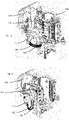
- Figure 1a shows a forming device according to the applicant's internal prior art in a closed state.
- This has a first side part carrier 142 and a second side part carrier 144 .
- These two side part supports 142 and 144 are arranged pivotably relative to a main support 106 .
- the reference number 112 designates a fastening device, by means of which two hose lines 182 and 184 are fastened to the main beam. The second ends of these hose lines open out here in an area of the side part support 142.
- Figure 1b shows the in Figure 1a shown forming device in an open state. It can be seen that here the side part supports move much closer to the fastening device 112 and in this way the hose lines 182, 184 are curved to a much greater extent and are therefore subjected to a much greater load.
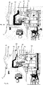
- Figure 2a shows a forming device according to the invention in a closed state.
- Reference number 42 refers to a first side part carrier and reference number 44 to a second side part carrier.
- These side part supports can be pivoted by means of a shaft to open and close the blow mold (not shown).
- the reference number 30 designates a locking device, by means of which the side part supports can be locked.
- the reference numeral 72 denotes a base part carrier, by means of which a base part (not shown) can also be brought up to the two side parts in order to close the blow mold.
- the reference number 70 designates a coupling mechanism, by means of which the movement of the base part carrier 72 is coupled to the movement of the side part carriers.
- Reference number 54 designates a drive device, here a cam roller, by means of which (with guide curves) the blow molds can be opened and closed.
- the reference number 12 designates a fastening device which is arranged on the main beam 6 .
- two first connecting line sections 92 and 94 lead to an actuator 14.
- two connecting line sections 82 and 84 in turn lead further to the blow mold support part 42 and two further connecting line sections 86 and 88 to the second side part support 44.
- Reference number 1 denotes the reshaping device and reference numeral 50 the reshaping device.
- Figure 2b shows the in figure 1 shown forming device in an open state. It can be seen that here the connecting line sections 82 and 84 are not significantly more curved than in the case of FIG Figure 2a Situation shown, since the actuator 14 with the opening movement here compared to figure 2 moved backwards.
- the reference numeral 52 designates an actuator carrier, which in turn is arranged on a carriage, the movement of which is mechanically coupled to the guide roller.
- the Figures 3a and 3b show a side view of the in the Figures 2a and 2b shown forming device.
- the carriage 52 is shown in particular, which (cf. figure 3 ) is placed in two different positions.
- the actuator 14 is also arranged on this carriage.
- the reference numeral 52′ accordingly indicates the position of the carrier 52 in FIG Figure 3a shown situation.
- FIGS. 4a and 4b show a plan view of the forming device according to the invention.
- the distance D1 along which the actuator 14 is moved can also be seen here in particular.
- the actuator also serves to distribute liquids to the two side part supports 42 and 44.
- the actuator 14 has a cavity in its interior in which liquid can be collected and/or distributed.
- figure 5 shows a schematic representation of an arrangement according to the invention for shaping plastic preforms 10 into plastic containers 20.
- This has a station support 15 on which a large number of shaping stations 1 and in particular shaping stations 1 according to the invention are arranged.
- Reference numerals 22 and 24 denote, roughly schematically, the side parts of a blow mold 2.
Landscapes
- Engineering & Computer Science (AREA)
- Manufacturing & Machinery (AREA)
- Mechanical Engineering (AREA)
- Blow-Moulding Or Thermoforming Of Plastics Or The Like (AREA)
- Moulds For Moulding Plastics Or The Like (AREA)
Claims (10)
- Dispositif (50) de façonnage de préformes en matière plastique (10) en des récipients en matière plastique (20), avec un système de façonnage (1) avec un premier support de partie latérale (42) et un deuxième support de partie latérale (44), dans lequel une première partie latérale (22) d'un moule de soufflage (2) peut être fixée au moins indirectement sur le premier support de partie latérale (42) et une deuxième partie latérale (24) du moule de soufflage (2) peut être fixée au moins indirectement sur le deuxième support de partie latérale (44), dans lequel lesdites parties latérales (22, 24) réalisent, dans un état fermé du moule de soufflage (2), au moins une partie d'une cavité, à l'intérieur de laquelle la préforme en matière plastique (10) peut être façonnée en le récipient en matière plastique (20) en le soumettant à l'action d'un milieu pouvant s'écouler et dans lequel le système de façonnage (1) est disposé sur un support principal (6), sur lequel au moins un support de partie latérale (42) est disposé de manière à pouvoir être déplacé par rapport à l'autre support de partie latérale (44) pour ouvrir et/ou fermer le moule de soufflage (2), dans lequel le système de façonnage (1) présente au moins un système d'alimentation (8) avec au moins une première conduite de raccordement (82, 84, 86, 88, 92, 94), dans lequel au moins un tronçon d'au moins une conduite de liaison (82, 84, 86, 88, 92, 94) est disposé de manière stationnaire par rapport au support principal (6) au moyen d'au moins un système de fixation (12) et dans lequel un tronçon de ladite conduite de raccordement (82, 84, 86, 88, 92, 94) est disposé sur un système du système de façonnage (1) de telle manière que ledit tronçon de la conduite de raccordement (82, 84, 86, 88, 92, 94) se déplace par rapport au système de déplacement (14) lors d'un déplacement du support de partie latérale (42, 44) par rapport au support principal (6), caractérisé en ce que
est disposé sur le dispositif (50) un organe de réglage (14), sur lequel au moins un tronçon de la conduite de raccordement (82, 84, 86, 88, 92, 94) est fixé, dans lequel ledit organe de réglage (14) peut être déplacé également par rapport au support principal (6). - Dispositif (50) selon la revendication 1,
caractérisé en ce que
la conduite de raccordement (82, 84, 86, 88, 92, 94) est une conduite de milieux. - Dispositif (50) selon au moins l'une quelconque des revendications précédentes,
caractérisé en ce que
l'au moins une conduite de raccordement (82, 84, 86, 88, 92, 94) est une conduite de raccordement (82, 84, 86, 88, 92, 94) flexible. - Dispositif (50) selon au moins l'une quelconque des revendications précédentes,
caractérisé en ce que
un déplacement de l'organe de réglage (14) par rapport au support principal (6) est couplé à un déplacement d'au moins un support de partie latérale (42, 44) par rapport au support principal (6). - Dispositif (50) selon la revendication précédente,
caractérisé en ce que
le déplacement de l'organe de réglage (14) est couplé de telle manière au déplacement du support de partie latérale (42, 44) que ledit déplacement contrecarre une modification de distance entre le support de partie latérale et l'organe de réglage. - Dispositif (50) selon au moins l'une quelconque des revendications précédentes,
caractérisé en ce que
au moins une conduite de raccordement présente un premier tronçon de conduite de raccordement (92, 94) et un deuxième tronçon de conduite de raccordement (82, 84, 86, 88), dans lequel le premier tronçon de conduite de raccordement et le deuxième tronçon de conduite de raccordement sont en communication fluidique l'un avec l'autre. - Dispositif (50) selon au moins l'une quelconque des revendications précédentes,
caractérisé en ce que
l'organe de réglage peut être déplacé dans une direction rectiligne et / ou l'organe de réglage peut être déplacé dans un plan de symétrie. - Dispositif (50) selon au moins l'une quelconque des revendications précédentes,
caractérisé en ce que
l'organe de réglage est réalisé également en tant que système de répartition de liquide (14). - Ensemble (100) pour façonner des préformes en matière plastique (10) en des récipients en matière plastique (20) avec un support central (18) pouvant être déplacé et en particulier pouvant être tourné, sur lequel une pluralité de dispositifs (50) selon au moins l'une quelconque des revendications précédentes est fixée.
- Procédé pour façonner des préformes en matière plastique (10) en des récipients en matière plastique (20) au moyen d'un système de façonnage (1) avec un premier support de partie latérale (42) et un deuxième support de partie latérale (44), dans lequel une première partie latérale (22) d'un moule de soufflage (2) est fixée au moins indirectement sur le premier support de partie latérale (42) et une deuxième partie latérale (24) du moule de soufflage (2) est fixée au moins indirectement sur le deuxième support de partie latérale (44), dans lequel lesdites parties latérales (22, 24) réalisent, dans un état fermé du moule de soufflage (2), au moins une partie d'une cavité, à l'intérieur de laquelle la préforme en matière plastique (10) est façonnée en le récipient en matière plastique (20) en la soumettant à l'action d'un milieu pouvant s'écouler, et dans lequel le système de façonnage (1) est disposé sur un support principal (6), sur lequel au moins un support de partie latérale (42) est déplacé par rapport à l'autre support de partie latérale (44) pour ouvrir et/ou fermer le moule de soufflage (2), dans lequel au moins un élément du système de façonnage (1) est alimenté au moyen d'un système d'alimentation (8), lequel présente au moins une première conduite de raccordement (82, 84, 86, 88, 92, 94), dans lequel au moins un tronçon d'au moins une conduite de raccordement (82, 84, 86, 88, 92, 94) est disposé de manière stationnaire par rapport au support principal (6) au moyen d'au moins un système de fixation (12) et dans lequel un tronçon de ladite conduite de raccordement (82, 84, 86, 88, 92, 94) est disposé sur un système du système de façonnage (1) de telle manière que ledit tronçon de la conduite de raccordement (82, 84, 86, 88, 92, 94) se déplace par rapport au système de fixation (14) et/ou au support principal lors d'un déplacement du support de partie latérale (42, 44) par rapport au support principal (6),
caractérisé en ce que
le dispositif (50) présente un organe de réglage (14), sur lequel au moins un tronçon de la conduite de raccordement (82, 84, 86, 88, 92, 94) est fixé, dans lequel ledit organe de réglage (14) se déplace également par rapport au support principal (6) lors de l'ouverture et/ou de la fermeture du moule de soufflage.
Applications Claiming Priority (2)
| Application Number | Priority Date | Filing Date | Title |
|---|---|---|---|
| DE102018123876.2A DE102018123876A1 (de) | 2018-09-27 | 2018-09-27 | Vorrichtung und Verfahren zum Umformen von Kunststoffvorformlingen zu Kunststoffbehältnissen mit Belastungsausgleich für Medienverbindungen |
| PCT/EP2019/076197 WO2020065018A1 (fr) | 2018-09-27 | 2019-09-27 | Dispositif et procédé pour mouler des ébauches en matière plastique en récipients en matière plastique, comprenant un équilibrage de contraintes pour des liaisons de transport de matière |
Publications (2)
| Publication Number | Publication Date |
|---|---|
| EP3856483A1 EP3856483A1 (fr) | 2021-08-04 |
| EP3856483B1 true EP3856483B1 (fr) | 2022-11-23 |
Family
ID=68138049
Family Applications (1)
| Application Number | Title | Priority Date | Filing Date |
|---|---|---|---|
| EP19782952.6A Active EP3856483B1 (fr) | 2018-09-27 | 2019-09-27 | Dispositif et procédé pour mouler des ébauches en matière plastique en récipients en matière plastique, comprenant un équilibrage de contraintes pour des liaisons de transport de matière |
Country Status (5)
| Country | Link |
|---|---|
| US (1) | US11390010B2 (fr) |
| EP (1) | EP3856483B1 (fr) |
| CN (1) | CN216885157U (fr) |
| DE (1) | DE102018123876A1 (fr) |
| WO (1) | WO2020065018A1 (fr) |
Families Citing this family (1)
| Publication number | Priority date | Publication date | Assignee | Title |
|---|---|---|---|---|
| EP4530045A1 (fr) * | 2023-09-28 | 2025-04-02 | KHS GmbH | Unité de moulage par soufflage pour une installation de moulage par soufflage |
Family Cites Families (7)
| Publication number | Priority date | Publication date | Assignee | Title |
|---|---|---|---|---|
| FR2939073B1 (fr) | 2008-12-03 | 2010-12-31 | Sidel Participations | Formage des recipients avec contre-pression localisee |
| FR2939070A1 (fr) * | 2008-12-03 | 2010-06-04 | Sidel Participations | Formage des recipients avec refroidissement localise |
| FR2954207B1 (fr) * | 2009-12-21 | 2013-09-27 | Sidel Participations | Machine pour la fabrication de recipients comportant un systeme d'assistance au changement de moule |
| DE102011116192A1 (de) * | 2010-10-13 | 2012-04-19 | Khs Corpoplast Gmbh | Verfahren und Vorrichtung zur Blasformung von Behältern |
| DE102013113361A1 (de) * | 2013-12-03 | 2015-06-03 | Krones Ag | Blasformmaschine mit am Blasrad angeordneten Austauschelementen |
| DE202015101602U1 (de) * | 2015-03-30 | 2015-04-20 | Krones Ag | Blasformmaschine mit gedämpftem Blasformbodenträger |
| DE102015117292A1 (de) * | 2015-10-09 | 2017-04-13 | Krones Ag | Blasformmaschine mit automatisch betätigbarer Bodenankopplung |
-
2018
- 2018-09-27 DE DE102018123876.2A patent/DE102018123876A1/de not_active Withdrawn
-
2019
- 2019-09-27 CN CN201990001029.8U patent/CN216885157U/zh active Active
- 2019-09-27 EP EP19782952.6A patent/EP3856483B1/fr active Active
- 2019-09-27 WO PCT/EP2019/076197 patent/WO2020065018A1/fr not_active Ceased
- 2019-09-27 US US17/281,213 patent/US11390010B2/en active Active
Also Published As
| Publication number | Publication date |
|---|---|
| US20210394422A1 (en) | 2021-12-23 |
| US11390010B2 (en) | 2022-07-19 |
| DE102018123876A1 (de) | 2020-04-02 |
| EP3856483A1 (fr) | 2021-08-04 |
| CN216885157U (zh) | 2022-07-05 |
| WO2020065018A1 (fr) | 2020-04-02 |
Similar Documents
| Publication | Publication Date | Title |
|---|---|---|
| EP2144742B1 (fr) | Dispositif de moulage par soufflage de récipients | |
| EP1979153B1 (fr) | Dispositif de moulage par soufflage de recipients dote d'elements de transport de type pince a deux bras | |
| EP1789247B1 (fr) | Dispositif de moulage par souffler de récipients | |
| EP2493674B1 (fr) | Dispositif de manipulation de pièces | |
| EP2753465B1 (fr) | Dispositif de transport de preformes pour le moulage par soufflage de recipients | |
| EP2114804B1 (fr) | Dispositif de moulage par soufflage de conteneurs | |
| DE102009021792A1 (de) | Vorrichtung und Verfahren zum Temperieren von Kunststoffvorformlingen | |
| DE102005011805A1 (de) | Verfahren und Vorrichtung zur Blasformung von Behältern | |
| DE102009006508A1 (de) | Verfahren und Vorrichtung zur Blasformung von Behältern | |
| DE102005017540A1 (de) | Verfahren und Vorrichtung zur Blasformung von Behältern | |
| EP3055120B1 (fr) | Procédé et dispositif pour la production d'un récipient rempli de matière de remplissage | |
| WO2017140330A1 (fr) | Disposition à pinces pour la manipulation de préformes et roue de transfert et machine de traitement de récipients présentant une telle disposition à pinces | |
| DE102014107512B4 (de) | Blasformeinrichtung mit vorspannbarer Befestigung für Blasformen | |
| EP2694270B1 (fr) | Dispositif pour le moulage de recipients par soufflage | |
| EP3856483A1 (fr) | Dispositif et procédé pour mouler des ébauches en matière plastique en récipients en matière plastique, comprenant un équilibrage de contraintes pour des liaisons de transport de matière | |
| EP2803469B1 (fr) | Machine de formage par soufflage dotée d'une commande séparée de coussin de pression | |
| EP3088160B1 (fr) | Procede et dispositif de transformation d'ebauches plastiques avec refroidissement de recipient | |
| DE102005045942A1 (de) | Verfahren und Vorrichtung zur Blasformung von Behältern | |
| DE102014019722A1 (de) | Blasformeinrichtung mit vorspannbarer Befestigung für Blasformen | |
| DE102005011804A1 (de) | Verfahren und Vorrichtung zur Blasformung von Behältern | |
| EP2768654B1 (fr) | Dispositif de retenue de pièces | |
| DE102024118724A1 (de) | Vorrichtung und Anlage zum Herstellen mindestens eines Behälters, Behälterherstellungsmaschine und Verfahren zum Steuern mindestens einer Behälterherstellungsmaschine | |
| WO2024223399A1 (fr) | Module de moulage par soufflage pour une installation de moulage par soufflage |
Legal Events
| Date | Code | Title | Description |
|---|---|---|---|
| STAA | Information on the status of an ep patent application or granted ep patent |
Free format text: STATUS: UNKNOWN |
|
| STAA | Information on the status of an ep patent application or granted ep patent |
Free format text: STATUS: THE INTERNATIONAL PUBLICATION HAS BEEN MADE |
|
| PUAI | Public reference made under article 153(3) epc to a published international application that has entered the european phase |
Free format text: ORIGINAL CODE: 0009012 |
|
| STAA | Information on the status of an ep patent application or granted ep patent |
Free format text: STATUS: REQUEST FOR EXAMINATION WAS MADE |
|
| 17P | Request for examination filed |
Effective date: 20210426 |
|
| AK | Designated contracting states |
Kind code of ref document: A1 Designated state(s): AL AT BE BG CH CY CZ DE DK EE ES FI FR GB GR HR HU IE IS IT LI LT LU LV MC MK MT NL NO PL PT RO RS SE SI SK SM TR |
|
| DAV | Request for validation of the european patent (deleted) | ||
| DAX | Request for extension of the european patent (deleted) | ||
| GRAP | Despatch of communication of intention to grant a patent |
Free format text: ORIGINAL CODE: EPIDOSNIGR1 |
|
| STAA | Information on the status of an ep patent application or granted ep patent |
Free format text: STATUS: GRANT OF PATENT IS INTENDED |
|
| RIC1 | Information provided on ipc code assigned before grant |
Ipc: B29L 31/00 20060101ALN20220425BHEP Ipc: B29C 49/56 20060101ALN20220425BHEP Ipc: B29C 49/36 20060101ALN20220425BHEP Ipc: B29C 49/06 20060101ALN20220425BHEP Ipc: B29C 49/58 20060101ALI20220425BHEP Ipc: B29C 49/48 20060101AFI20220425BHEP |
|
| RIC1 | Information provided on ipc code assigned before grant |
Ipc: B29L 31/00 20060101ALN20220504BHEP Ipc: B29C 49/56 20060101ALN20220504BHEP Ipc: B29C 49/36 20060101ALN20220504BHEP Ipc: B29C 49/06 20060101ALN20220504BHEP Ipc: B29C 49/58 20060101ALI20220504BHEP Ipc: B29C 49/48 20060101AFI20220504BHEP |
|
| INTG | Intention to grant announced |
Effective date: 20220517 |
|
| GRAJ | Information related to disapproval of communication of intention to grant by the applicant or resumption of examination proceedings by the epo deleted |
Free format text: ORIGINAL CODE: EPIDOSDIGR1 |
|
| STAA | Information on the status of an ep patent application or granted ep patent |
Free format text: STATUS: REQUEST FOR EXAMINATION WAS MADE |
|
| GRAS | Grant fee paid |
Free format text: ORIGINAL CODE: EPIDOSNIGR3 |
|
| STAA | Information on the status of an ep patent application or granted ep patent |
Free format text: STATUS: GRANT OF PATENT IS INTENDED |
|
| GRAP | Despatch of communication of intention to grant a patent |
Free format text: ORIGINAL CODE: EPIDOSNIGR1 |
|
| INTC | Intention to grant announced (deleted) | ||
| RIC1 | Information provided on ipc code assigned before grant |
Ipc: B29L 31/00 20060101ALN20220906BHEP Ipc: B29C 49/56 20060101ALN20220906BHEP Ipc: B29C 49/36 20060101ALN20220906BHEP Ipc: B29C 49/06 20060101ALN20220906BHEP Ipc: B29C 49/58 20060101ALI20220906BHEP Ipc: B29C 49/48 20060101AFI20220906BHEP |
|
| INTG | Intention to grant announced |
Effective date: 20220922 |
|
| GRAA | (expected) grant |
Free format text: ORIGINAL CODE: 0009210 |
|
| STAA | Information on the status of an ep patent application or granted ep patent |
Free format text: STATUS: THE PATENT HAS BEEN GRANTED |
|
| AK | Designated contracting states |
Kind code of ref document: B1 Designated state(s): AL AT BE BG CH CY CZ DE DK EE ES FI FR GB GR HR HU IE IS IT LI LT LU LV MC MK MT NL NO PL PT RO RS SE SI SK SM TR |
|
| REG | Reference to a national code |
Ref country code: GB Ref legal event code: FG4D Free format text: NOT ENGLISH |
|
| REG | Reference to a national code |
Ref country code: CH Ref legal event code: EP |
|
| REG | Reference to a national code |
Ref country code: AT Ref legal event code: REF Ref document number: 1532876 Country of ref document: AT Kind code of ref document: T Effective date: 20221215 Ref country code: DE Ref legal event code: R096 Ref document number: 502019006368 Country of ref document: DE |
|
| REG | Reference to a national code |
Ref country code: IE Ref legal event code: FG4D Free format text: LANGUAGE OF EP DOCUMENT: GERMAN |
|
| REG | Reference to a national code |
Ref country code: LT Ref legal event code: MG9D |
|
| REG | Reference to a national code |
Ref country code: NL Ref legal event code: MP Effective date: 20221123 |
|
| PG25 | Lapsed in a contracting state [announced via postgrant information from national office to epo] |
Ref country code: SE Free format text: LAPSE BECAUSE OF FAILURE TO SUBMIT A TRANSLATION OF THE DESCRIPTION OR TO PAY THE FEE WITHIN THE PRESCRIBED TIME-LIMIT Effective date: 20221123 Ref country code: PT Free format text: LAPSE BECAUSE OF FAILURE TO SUBMIT A TRANSLATION OF THE DESCRIPTION OR TO PAY THE FEE WITHIN THE PRESCRIBED TIME-LIMIT Effective date: 20230323 Ref country code: NO Free format text: LAPSE BECAUSE OF FAILURE TO SUBMIT A TRANSLATION OF THE DESCRIPTION OR TO PAY THE FEE WITHIN THE PRESCRIBED TIME-LIMIT Effective date: 20230223 Ref country code: LT Free format text: LAPSE BECAUSE OF FAILURE TO SUBMIT A TRANSLATION OF THE DESCRIPTION OR TO PAY THE FEE WITHIN THE PRESCRIBED TIME-LIMIT Effective date: 20221123 Ref country code: FI Free format text: LAPSE BECAUSE OF FAILURE TO SUBMIT A TRANSLATION OF THE DESCRIPTION OR TO PAY THE FEE WITHIN THE PRESCRIBED TIME-LIMIT Effective date: 20221123 Ref country code: ES Free format text: LAPSE BECAUSE OF FAILURE TO SUBMIT A TRANSLATION OF THE DESCRIPTION OR TO PAY THE FEE WITHIN THE PRESCRIBED TIME-LIMIT Effective date: 20221123 |
|
| PG25 | Lapsed in a contracting state [announced via postgrant information from national office to epo] |
Ref country code: RS Free format text: LAPSE BECAUSE OF FAILURE TO SUBMIT A TRANSLATION OF THE DESCRIPTION OR TO PAY THE FEE WITHIN THE PRESCRIBED TIME-LIMIT Effective date: 20221123 Ref country code: PL Free format text: LAPSE BECAUSE OF FAILURE TO SUBMIT A TRANSLATION OF THE DESCRIPTION OR TO PAY THE FEE WITHIN THE PRESCRIBED TIME-LIMIT Effective date: 20221123 Ref country code: LV Free format text: LAPSE BECAUSE OF FAILURE TO SUBMIT A TRANSLATION OF THE DESCRIPTION OR TO PAY THE FEE WITHIN THE PRESCRIBED TIME-LIMIT Effective date: 20221123 Ref country code: IS Free format text: LAPSE BECAUSE OF FAILURE TO SUBMIT A TRANSLATION OF THE DESCRIPTION OR TO PAY THE FEE WITHIN THE PRESCRIBED TIME-LIMIT Effective date: 20230323 Ref country code: HR Free format text: LAPSE BECAUSE OF FAILURE TO SUBMIT A TRANSLATION OF THE DESCRIPTION OR TO PAY THE FEE WITHIN THE PRESCRIBED TIME-LIMIT Effective date: 20221123 Ref country code: GR Free format text: LAPSE BECAUSE OF FAILURE TO SUBMIT A TRANSLATION OF THE DESCRIPTION OR TO PAY THE FEE WITHIN THE PRESCRIBED TIME-LIMIT Effective date: 20230224 |
|
| P01 | Opt-out of the competence of the unified patent court (upc) registered |
Effective date: 20230523 |
|
| PG25 | Lapsed in a contracting state [announced via postgrant information from national office to epo] |
Ref country code: NL Free format text: LAPSE BECAUSE OF FAILURE TO SUBMIT A TRANSLATION OF THE DESCRIPTION OR TO PAY THE FEE WITHIN THE PRESCRIBED TIME-LIMIT Effective date: 20221123 |
|
| PG25 | Lapsed in a contracting state [announced via postgrant information from national office to epo] |
Ref country code: SM Free format text: LAPSE BECAUSE OF FAILURE TO SUBMIT A TRANSLATION OF THE DESCRIPTION OR TO PAY THE FEE WITHIN THE PRESCRIBED TIME-LIMIT Effective date: 20221123 Ref country code: RO Free format text: LAPSE BECAUSE OF FAILURE TO SUBMIT A TRANSLATION OF THE DESCRIPTION OR TO PAY THE FEE WITHIN THE PRESCRIBED TIME-LIMIT Effective date: 20221123 Ref country code: EE Free format text: LAPSE BECAUSE OF FAILURE TO SUBMIT A TRANSLATION OF THE DESCRIPTION OR TO PAY THE FEE WITHIN THE PRESCRIBED TIME-LIMIT Effective date: 20221123 Ref country code: DK Free format text: LAPSE BECAUSE OF FAILURE TO SUBMIT A TRANSLATION OF THE DESCRIPTION OR TO PAY THE FEE WITHIN THE PRESCRIBED TIME-LIMIT Effective date: 20221123 Ref country code: CZ Free format text: LAPSE BECAUSE OF FAILURE TO SUBMIT A TRANSLATION OF THE DESCRIPTION OR TO PAY THE FEE WITHIN THE PRESCRIBED TIME-LIMIT Effective date: 20221123 |
|
| REG | Reference to a national code |
Ref country code: DE Ref legal event code: R097 Ref document number: 502019006368 Country of ref document: DE |
|
| PG25 | Lapsed in a contracting state [announced via postgrant information from national office to epo] |
Ref country code: SK Free format text: LAPSE BECAUSE OF FAILURE TO SUBMIT A TRANSLATION OF THE DESCRIPTION OR TO PAY THE FEE WITHIN THE PRESCRIBED TIME-LIMIT Effective date: 20221123 Ref country code: AL Free format text: LAPSE BECAUSE OF FAILURE TO SUBMIT A TRANSLATION OF THE DESCRIPTION OR TO PAY THE FEE WITHIN THE PRESCRIBED TIME-LIMIT Effective date: 20221123 |
|
| PLBE | No opposition filed within time limit |
Free format text: ORIGINAL CODE: 0009261 |
|
| STAA | Information on the status of an ep patent application or granted ep patent |
Free format text: STATUS: NO OPPOSITION FILED WITHIN TIME LIMIT |
|
| 26N | No opposition filed |
Effective date: 20230824 |
|
| PG25 | Lapsed in a contracting state [announced via postgrant information from national office to epo] |
Ref country code: SI Free format text: LAPSE BECAUSE OF FAILURE TO SUBMIT A TRANSLATION OF THE DESCRIPTION OR TO PAY THE FEE WITHIN THE PRESCRIBED TIME-LIMIT Effective date: 20221123 |
|
| REG | Reference to a national code |
Ref country code: CH Ref legal event code: PL |
|
| PG25 | Lapsed in a contracting state [announced via postgrant information from national office to epo] |
Ref country code: LU Free format text: LAPSE BECAUSE OF NON-PAYMENT OF DUE FEES Effective date: 20230927 |
|
| REG | Reference to a national code |
Ref country code: BE Ref legal event code: MM Effective date: 20230930 |
|
| GBPC | Gb: european patent ceased through non-payment of renewal fee |
Effective date: 20230927 |
|
| PG25 | Lapsed in a contracting state [announced via postgrant information from national office to epo] |
Ref country code: LU Free format text: LAPSE BECAUSE OF NON-PAYMENT OF DUE FEES Effective date: 20230927 Ref country code: MC Free format text: LAPSE BECAUSE OF FAILURE TO SUBMIT A TRANSLATION OF THE DESCRIPTION OR TO PAY THE FEE WITHIN THE PRESCRIBED TIME-LIMIT Effective date: 20221123 |
|
| REG | Reference to a national code |
Ref country code: IE Ref legal event code: MM4A |
|
| PG25 | Lapsed in a contracting state [announced via postgrant information from national office to epo] |
Ref country code: IE Free format text: LAPSE BECAUSE OF NON-PAYMENT OF DUE FEES Effective date: 20230927 |
|
| PG25 | Lapsed in a contracting state [announced via postgrant information from national office to epo] |
Ref country code: GB Free format text: LAPSE BECAUSE OF NON-PAYMENT OF DUE FEES Effective date: 20230927 |
|
| PG25 | Lapsed in a contracting state [announced via postgrant information from national office to epo] |
Ref country code: CH Free format text: LAPSE BECAUSE OF NON-PAYMENT OF DUE FEES Effective date: 20230930 |
|
| PG25 | Lapsed in a contracting state [announced via postgrant information from national office to epo] |
Ref country code: IE Free format text: LAPSE BECAUSE OF NON-PAYMENT OF DUE FEES Effective date: 20230927 Ref country code: GB Free format text: LAPSE BECAUSE OF NON-PAYMENT OF DUE FEES Effective date: 20230927 Ref country code: CH Free format text: LAPSE BECAUSE OF NON-PAYMENT OF DUE FEES Effective date: 20230930 |
|
| PG25 | Lapsed in a contracting state [announced via postgrant information from national office to epo] |
Ref country code: BE Free format text: LAPSE BECAUSE OF NON-PAYMENT OF DUE FEES Effective date: 20230930 |
|
| PG25 | Lapsed in a contracting state [announced via postgrant information from national office to epo] |
Ref country code: BG Free format text: LAPSE BECAUSE OF FAILURE TO SUBMIT A TRANSLATION OF THE DESCRIPTION OR TO PAY THE FEE WITHIN THE PRESCRIBED TIME-LIMIT Effective date: 20221123 |
|
| PG25 | Lapsed in a contracting state [announced via postgrant information from national office to epo] |
Ref country code: BG Free format text: LAPSE BECAUSE OF FAILURE TO SUBMIT A TRANSLATION OF THE DESCRIPTION OR TO PAY THE FEE WITHIN THE PRESCRIBED TIME-LIMIT Effective date: 20221123 |
|
| PG25 | Lapsed in a contracting state [announced via postgrant information from national office to epo] |
Ref country code: CY Free format text: LAPSE BECAUSE OF FAILURE TO SUBMIT A TRANSLATION OF THE DESCRIPTION OR TO PAY THE FEE WITHIN THE PRESCRIBED TIME-LIMIT; INVALID AB INITIO Effective date: 20190927 |
|
| PG25 | Lapsed in a contracting state [announced via postgrant information from national office to epo] |
Ref country code: HU Free format text: LAPSE BECAUSE OF FAILURE TO SUBMIT A TRANSLATION OF THE DESCRIPTION OR TO PAY THE FEE WITHIN THE PRESCRIBED TIME-LIMIT; INVALID AB INITIO Effective date: 20190927 |
|
| PGFP | Annual fee paid to national office [announced via postgrant information from national office to epo] |
Ref country code: DE Payment date: 20250805 Year of fee payment: 7 |
|
| PGFP | Annual fee paid to national office [announced via postgrant information from national office to epo] |
Ref country code: IT Payment date: 20250825 Year of fee payment: 7 |
|
| PGFP | Annual fee paid to national office [announced via postgrant information from national office to epo] |
Ref country code: FR Payment date: 20250808 Year of fee payment: 7 |
|
| REG | Reference to a national code |
Ref country code: AT Ref legal event code: MM01 Ref document number: 1532876 Country of ref document: AT Kind code of ref document: T Effective date: 20240927 |
|
| PG25 | Lapsed in a contracting state [announced via postgrant information from national office to epo] |
Ref country code: TR Free format text: LAPSE BECAUSE OF FAILURE TO SUBMIT A TRANSLATION OF THE DESCRIPTION OR TO PAY THE FEE WITHIN THE PRESCRIBED TIME-LIMIT Effective date: 20221123 |
|
| PG25 | Lapsed in a contracting state [announced via postgrant information from national office to epo] |
Ref country code: AT Free format text: LAPSE BECAUSE OF NON-PAYMENT OF DUE FEES Effective date: 20240927 |
|
| PGFP | Annual fee paid to national office [announced via postgrant information from national office to epo] |
Ref country code: AT Payment date: 20260410 Year of fee payment: 5 |